HOLIDAY DONATION DRIVE - SUPPORT MSW - DO YOUR PART TO KEEP THIS GREAT FORUM GOING! (Only 51 donations so far out of 49,000 members - C'mon guys!)
×


Jim Lad
-
Posts
9,502 -
Joined
-
Last visited
Content Type
Profiles
Forums
Gallery
Events
Everything posted by Jim Lad
-
Hello Victor, and a warm welcome to MSW. John
-
 Just catching up again, Danny. She's really starting to come together. John
- 295 replies
-
- 3
-

-
- amatsukaze
- halinski
- (and 2 more)
-
Bob, she certainly had rope ratlines during her working life, but if you are modelling her as a training ship in the 1930's, then boards would be correct, as shown in the photos in Nepean-longridge's book. I believe that she also had other rigging changes at this time, so some research would be needed to achieve accuracy if you are modelling her as a training ship. John
-
Carl, a right handed propeller on the starboard side and a left handed propeller on the port side (as Danny has fitted them) will turn outward when the ship is going ahead. John
- 295 replies
-
- 4
-
-
- amatsukaze
- halinski
- (and 2 more)
-
Hello Don, and a warm welcome to the forum from 'Down Under'. John
-
Beautifully done, Danny (and on the correct sides ). It's easy to get them right - in multi screw ships the propellers should turn outwards-but do your research as in a few notable cases even significant ships were built with inward turning propellers! John
- 295 replies
-
- 2
-
-
- amatsukaze
- halinski
- (and 2 more)
-
It sounds like you're starting to get into the swing of the planking now, Vaddoc. As the twist on the planks gets progressively more severe, you may need a bit more aggressive steaming to make the wood compliant. John
-
It's great to see Scale Hardware as a sponsor. I've browsed there web sit on several occasions - a mind boggling array of goodies! John
-
HMCSS Victoria 1855 by BANYAN - 1:72
Jim Lad replied to BANYAN's topic in - Build logs for subjects built 1851 - 1900
Pat, the first reference I came across was in R.N. Newton's "Practical Construction Of Warships" of 1941 (page 246). John- 1,006 replies
-
- 2
-
-
- gun dispatch vessel
- victoria
- (and 2 more)
-
Beautifully done, Danny. Just don't forget to put the propellers on their correct sides! John
- 295 replies
-
- 3
-
-
- amatsukaze
- halinski
- (and 2 more)
-
HMCSS Victoria 1855 by BANYAN - 1:72
Jim Lad replied to BANYAN's topic in - Build logs for subjects built 1851 - 1900
Pat, I can't find any reference to 'towing timbers' but there are a lot of references to 'towing bollards' for iron and steel ships, so your surmise may well be correct, especially given the detail of, "each timber having an iron cap over it with a pin through the head." John- 1,006 replies
-
- 2
-
-
- gun dispatch vessel
- victoria
- (and 2 more)
-
G'day Shoosh, and another warm welcome from 'Down Under'. Re stupid questions - the only stupid ones are the ones you don't ask because you think they might be too simple. We're a friendly mob here and always ready to answer questions. John
-
A pretty good job of paint matching there, Danny! John
- 295 replies
-
- 5
-
-
- amatsukaze
- halinski
- (and 2 more)
-
Danny, I've made a very slow start on my model of the 'Meteor', but life keeps getting in the way. I also keep forgetting to take my camera to the museum. Soon - I promise. John
- 295 replies
-
- 6
-
-
- amatsukaze
- halinski
- (and 2 more)
-
HMCSS Victoria 1855 by BANYAN - 1:72
Jim Lad replied to BANYAN's topic in - Build logs for subjects built 1851 - 1900
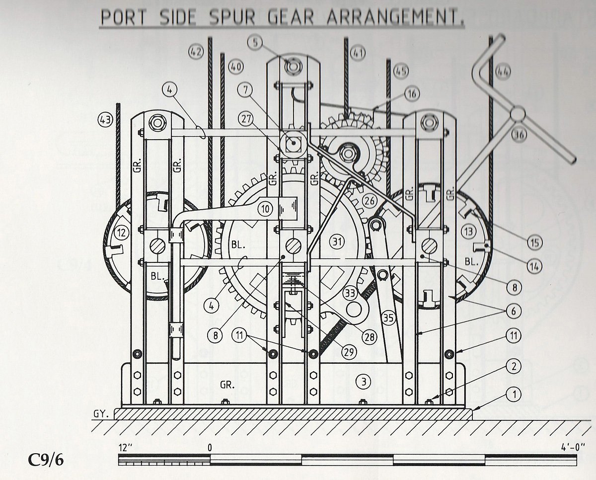
Pat, The drawing below is one of the detail drawings of a Jarvis brace winch in the Anatomy of the Ship series "The Four Masted Barque Lawhill". I think it will have enough detail for comparison - especially given the scale shown at the bottom. John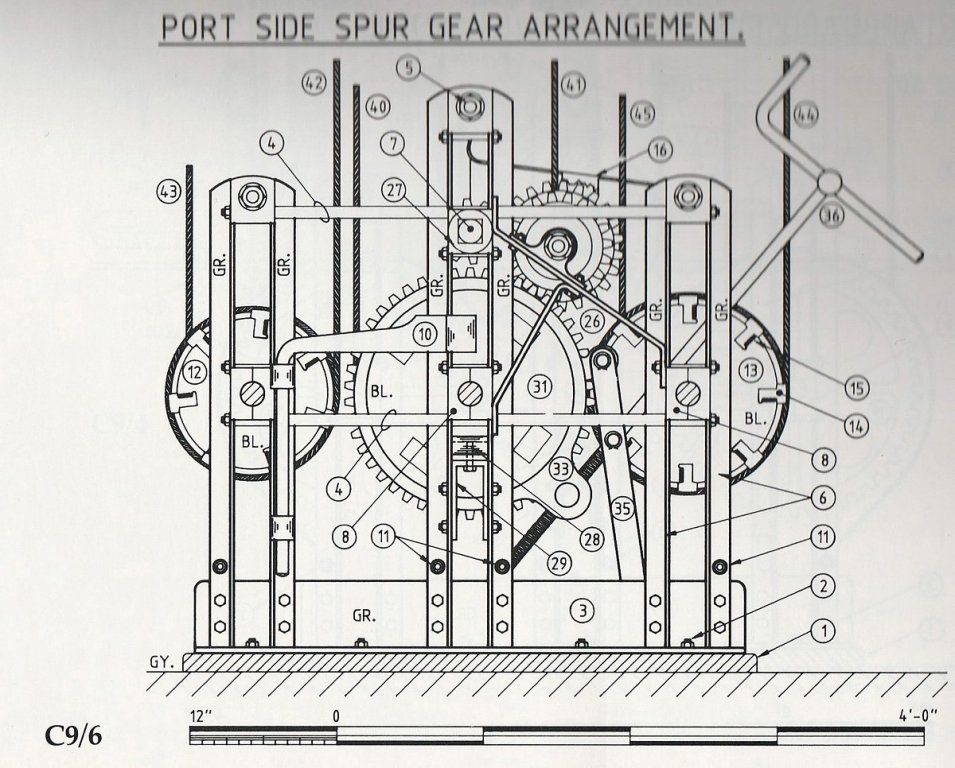
- 1,006 replies
-
- 6
-
-
- gun dispatch vessel
- victoria
- (and 2 more)
-
Just catching up, Adrian - she continues to delight! John
- 184 replies
-
- 3
-
-
- ruby & arthur reed
- lifeboat
- (and 1 more)
-
I think you're doing really well, Danny. I wouldn't be game to touch a card model. John
- 295 replies
-
- 4
-
-
- amatsukaze
- halinski
- (and 2 more)
-
HMCSS Victoria 1855 by BANYAN - 1:72
Jim Lad replied to BANYAN's topic in - Build logs for subjects built 1851 - 1900
Pat, I'm sure I've got drawings of a Jarvis brace winch in one of my books somewhere, so if you have trouble sourcing them, give me a yell. John- 1,006 replies
-
- 1
-
-
- gun dispatch vessel
- victoria
- (and 2 more)
-
HMCSS Victoria 1855 by BANYAN - 1:72
Jim Lad replied to BANYAN's topic in - Build logs for subjects built 1851 - 1900
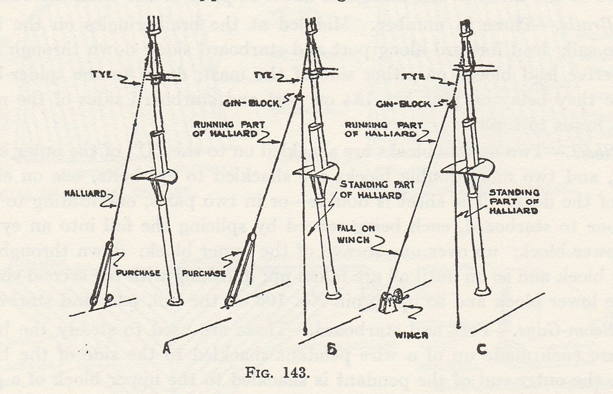
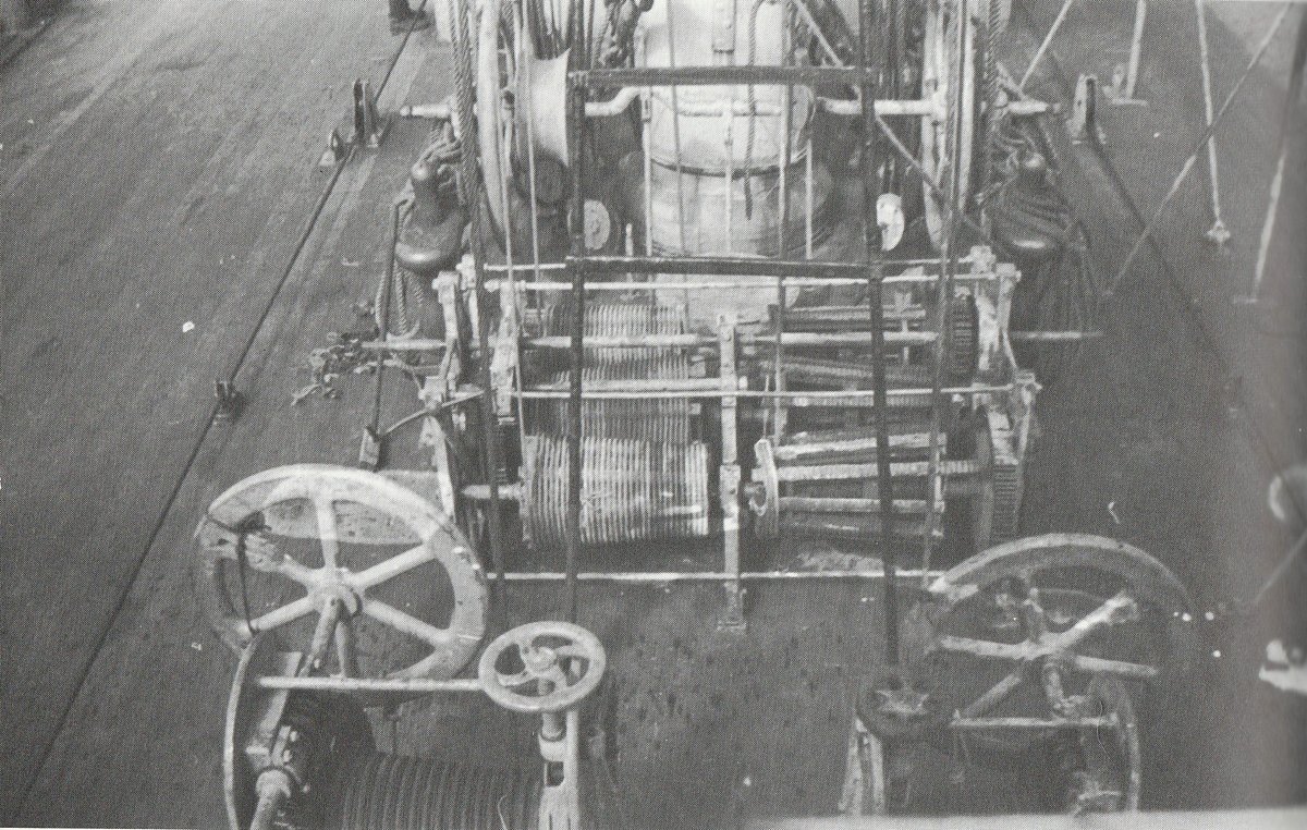
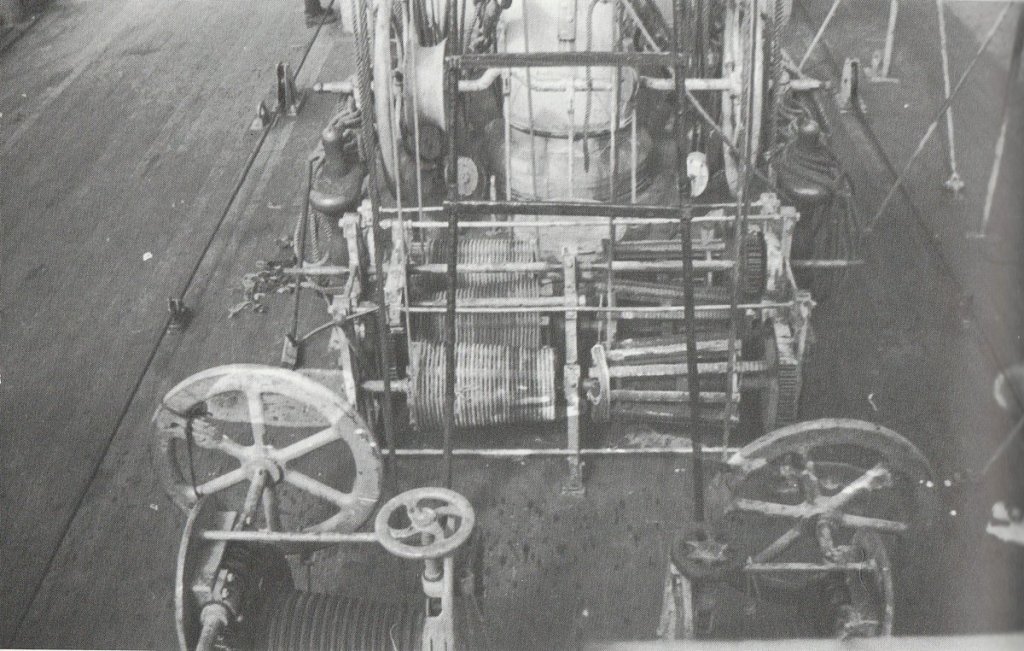
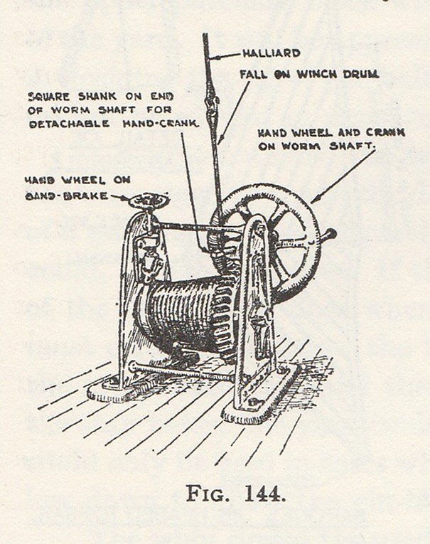
Pat, I've been able to find very little about halyard winches - they were a late innovation and perhaps not nearly as popular as brace winches, as many later ships seem to have had capstans to handle their halyards. The winches were obviously more labour saving as the halyard didn't have to be transferred from the winch to a pin rail - it simple stayed cailed on the winch. The two drawings are from Harold Underhill's "Masting and Rigging" - an truly excellent resource for late square rig - and are a sketch of a halyard winch and a diagrammatic view of the run of the halyard to a winch (example C). The photo is from Basil Greenhill's "Seafaring Under Sail" and shows the after side of one of the masts of an in-named four masted barque. The photo has obviously been taken to show the brace winch, but at the bottom you can see most of two halyard winches sitting side by side. Sorry I haven't got any more for you, but if anything else turns up I'll certainly let you know. John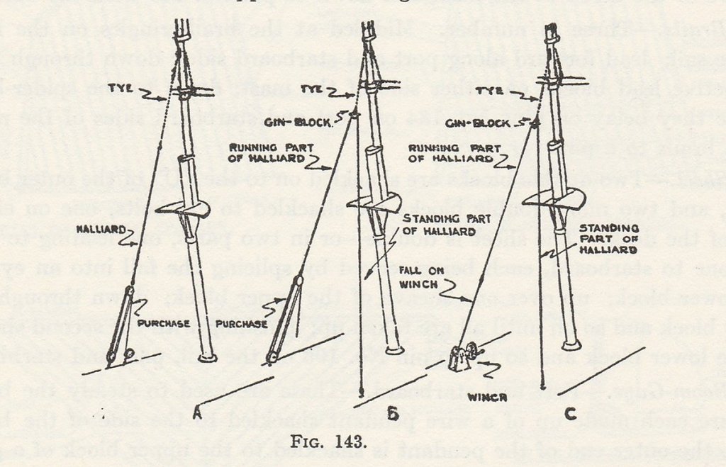
- 1,006 replies
-
- 5
-
-
- gun dispatch vessel
- victoria
- (and 2 more)