

minimini
-
Posts
56 -
Joined
-
Last visited
Reputation Activity
-

 minimini got a reaction from Archi in HMS Tiger 1747 by Siggi52 - 1:48 - 60 gun ship from NMM plans
Hi Druxey
Yes, you're right, I've looked up drawings back from 1705 until 1820
and they all show the same thing, like this one from 1728
Michael
-
.thumb.jpeg.fc5d633a7b34428fcf19419a73d56d55.jpeg) minimini got a reaction from EricWilliamMarshall in HMS Tiger 1747 by Siggi52 - 1:48 - 60 gun ship from NMM plans
minimini got a reaction from EricWilliamMarshall in HMS Tiger 1747 by Siggi52 - 1:48 - 60 gun ship from NMM plans
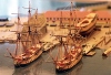
Hello Siggi
I have found this drawing in the Danish archive. It's a plan of a Danish 90-gun ship of the line from 1766, I have 3-4 drawings more that show the same
Michael
-
minimini reacted to Siggi52 in HMS Tiger 1747 by Siggi52 - 1:48 - 60 gun ship from NMM plans
Hello,
today I finished the planking of the port side, between the wales. These gun ports slow your really down and I have a lot more of them above the upper wales
-
minimini reacted to JOUFF in La Renommée by JOUFF - 1/48 - French Frigate - by Patrick JOUFFRIN
Hello gentlemen !
Here is the continuation with the interior fittings :
Patrick
-
minimini reacted to Chuck in Pegasus 1776 by Chuck - 1:48 - Swan-class sloop cross-section
Thank you guys. I wanted to show the test set up with one of the actual cherry frames in position. This will be an actual frame I use on the model as opposed to the other tests I posted. This final version is slightly different in that it is done with chocks. You can see the chock between the futtock and toptimber . Its is not an actual chock but it is impossible to tell the difference. I just used a laser etched line to complete the appearance of a chock and it only shows on one side of the frame. This is important for the outside frames because it completes the look of actual framing practices. But the other side just shows the simple scarf joint.
The frames will be so close together that you wont be able to see that. To complete the simulation, I just drew a line with a very sharp pencil along the inboard edge of the frame. This will have to be redone once the inboard frames are faired but you can see how nice it looks. It will make the open framed port side look really authentic. Especially after treenailing is done. If you really wanted to, you could complete the illusion on the other side of each frame with a pencil...but seriously it would be impossible to see.
-
minimini reacted to SJSoane in HMS Bellona 1760 by SJSoane - Scale 1:64 - English 74-gun - as designed
Thank you, Gary, druxey and Håkan for your kind comments. It helps me keep going.
druxey, thank you for confirming that I should work on the port side top two strakes, before going back to the starboard lower two strakes. I want to trap the frame on both sides as close to the same time as possible, when the humidity is roughly the same. I worry about unequal pull on the two sides if one is restrained and the other is not when the humidity changes.
Last time, I fiddled with a variety of clamps at the bow. This time, I fashioned a wooden block that can be clamped against the bow by way of the back of the stem. It provides a good, clean, simple way of clamping. I need to take the time to make special clamps like this in the future; worth the extra time for a clean assembly process.
I also experimented with steaming and clamping the top plank on the port side directly to the hull, not to my former. The next day, the spring-back was so great that I steamed the piece again and clamped it in the former, now upside down, to make the piece symmetrical to the starboard piece. It now lays nicely against the hull.
Time to watch the Olympics!
Mark
-
minimini reacted to matiz in French 74-gun ship by matiz - scale 1:56 - Tiziano Mainardi
Hi, and tanks, Alberto
-
minimini reacted to SJSoane in HMS Bellona 1760 by SJSoane - Scale 1:64 - English 74-gun - as designed
Thank you, Alan and Mike, for encouraging incremental posts on the wales construction. Here is the next phase.
The sternmost planks of the wales were more challenging than I had expected, with the wicked twist to the stern counter. I haven't followed up on using a heat gun for bending, so had to wait overnight a few times for the steam bending to dry. I used artists' graphite paper to fit one plank to another. Squeeze the joint together with the paper in between, pull the paper through, and it shows highlights that need to be filed or sanded down. The last hi res photos shows how accurate this can be (thanks, Greg, for encouraging me into the occasional hi res photo). I also made long sanding sticks shaped to the curve of the wales (first photo), which help even up the lower edge ready for the next strake below.
I can see that sanding the wale to the counter is going to be challenging, avoiding accidentally marring the finished counter surface. I will leave these a little proud and turn the hull upside down for final shaping when both full wales are in. I can't see clearly enough what is happening with filing when the hull is upright.
I think I had better start on the port side before tackling the lower two strakes on the starboard side, just in case I start getting differential pull between the now constrained starboard side and the still unconstrained port side as the humidity changes.
Mark
-
minimini reacted to garyshipwright in HMS Montague 1779 by garyshipwright - 74-gun Alfred-class
Well guys I finally got to a point that figure I would do a up date on Montagu. As I had posted some where, may here or on Marks log of the Bellona that I had placed my channels wales to high and had to remove them and lower them closer to the gun deck ports. Don't ask me how, maybe along the same line as redoing the cant frames more then once but they now reside in the right place. Had to take a few addition planks off of her, guess I just didn't like their look of them. Also been working on the cheeks and the quarter deck gun ports and happy to report, they are in the right place and one more piece and they will be done. Also installed some battern's to help with the placement of the upper railes, in the near future. That is as soon as I am happy with how they look. Gary
-
minimini reacted to mtaylor in Licorne 1755 by mtaylor - 3/16" scale - French Frigate - from Hahn plans - Version 2.0 - TERMINATED
Thanks for the likes and comments. It feels pretty good to be back in shop.
Still sanding but made a jig today for drilling the gunport holes for the eyebolts. Pictures show front and back of next to the dummy cannon. The eyebolts are them for reference only.
-
minimini reacted to Chuck in Help decide next project for Syren Ship Model Company
Drafting underway...just an hour or two every now and again when my girls are watching something stupid on TV. So I sit with them but have my laptop with me while I pretend to be just a little interested.
-
minimini reacted to mtaylor in Licorne 1755 by mtaylor - 3/16" scale - French Frigate - from Hahn plans - Version 2.0 - TERMINATED
Thanks for the likes and comments. They are deeply appreciated and encouraging.
I finished the planking the interior of the gundeck and have sanded it all pretty smooth. Still needs another pass with the sandpaper, IMO, along with some crack filling. I also need to make some "trim" bits (fiddly) for the cabin. To break the monotony of sanding, I have started work on the gun carriages. I just need to find a good time to start the guns themselves.
Here's the pics as she stands in the shipyard today. I'm running an inventory of eyebolts, rings, and some blocks to see if I have enough to fit out what's needed on this deck as well as the outside hull.
-
minimini reacted to ChrisLBren in La Renommee 1744 by ChrisLBren - 1/48 Scale
Good Morning Group,
I have cut out the first piece for the keel assembly - approximately two hours using most of my tools - the Byrnes Thickness Sander for final dimensioning of the billet, the DeWalt Scroll Saw, Spindle Sander and Byrnes Disc Sander. I am hoping to become more efficient with the scroll saw - which would have cut down the amount of sanding time therefore producing the piece in less time. I have noticed slowing the speed down on the scroll saw (at least for me) produces a more controllable cut. It still felt great to be back at building and having fun with my new tools !
First observations - this new pear cuts cleanly and will finish beautifully - this piece is only sanded to 220. Its a bit harder and lighter than the wood I used for Confederacy - which I prefer. If i could just get my kids to sleep in I wouldn't be interrupted after only an hour of work. 4am to 6am is my workshop time - and they've been getting up at 5 for some reason - probably to torment me....
-
minimini reacted to Erebus and Terror in HMS Terror by Erebus and Terror - FINISHED - Scale 1:48 - POB - as fitted for polar service in 1845
THE GREAT PLANKING OF 2017 (Part 1)
Special attention was paid to HMS Terror’s planking; originally, to protect her from the recoil of her massive mortars within, and later to protect her from the immense force of polar ice without. These combined pressures resulted in the construction of perhaps the toughest wooden sailing vessel the world has ever seen. She was, in her way, the pinnacle of the wooden shipwright’s art - embodied in a squat, slab-sided bomb, with the lines and dull sailing qualities of a merchantman. How can you not love HMS Terror?
My reconstruction of Terror's 1845 planking plan.
Please visit my blog for the complete description of Terror's planking desgn and history.
I made two fundamental mistakes when planning to plank Terror’s hull in 2013. The first of these was deciding to double-plank her hull, just like the real ship. I began planking my model in the fall of 2016. In a previous post, I showed how I planked Terror’s topside weatherworks above the chocks. I followed a similar methodology for the hull, but rather than edge-bending planks, I had to carefully spile them, as this was necessary to plank the bluffer parts of Terror’s bow.
The first strake added to the hull. The white line was my first inadequate
attempt to line off the bottom of the wales. I fixed the run shortly after this picture was taken.
The first strake at the bow. This image reveals how bluff Terror was just above the waterline.
Again, this was taken before I adjusted the reference line on the hull.
Spiling greatly slowed my progress, and I was only able to complete one or two strakes in an evening. With 120 strakes necessary for both layers of hull planking, not including the ice chocks, stern, and upper deck, I rapidly realized that I was facing a crisis. The deadline to deliver my model for the Death in the Ice exhibition was in June of 2017, and it quickly became apparent that I would not make that deadline if I did not increase my output. Thus, I began the great planking of 2017.
It began with a compromise. To speed up the first layer of planking, I decided to double the width of each of the lower hull strakes and to not follow the accurate plank shift pattern (which requires more cutting). While this layer will never be visible, I regret not having completed it to scale; in addition, not having a photograph of Terror’s original planking configuration remains a sincere source of dissatisfaction for me.
My second mistake was to plank the second layer of my model using accurate scale plank thicknesses. Some of the planks on Terror’s wales are 8 inches thick, representing a daunting task at 1:48th scale. While the three and four-inch scale planks could easily be bent with a crimping tool and some heat from a blow dryer, this technique simply would not work on planks thicker than five scale inches. Every thick plank had to be soaked in near-boiling water for 20 minutes, carefully crimped with a plank bender, and then pressed into shape using a bending iron and a curved jig. On top of that, each plank had to be carefully spiled before bending, and the distortion caused by swelling wood and heat treatment caused no end of difficulty. An added complication was that the thickest strakes, at the wales, had to be laid top and butt fashion, which further complicated the spiling process.
The second layer of planking in progress. You can see here where I made the decision to
widen each strake on the first layer (about January 2017).
Detail showing the transition to 8" strakes at wales. The upper two 8" stakes were sanded
to provide a smooth run to the 6" planks above them.
The third strake of 8" top and butt planking at the bow. Notice the
drop strake below it in the first layer of planking.
Top and butt planking in progress. The tape protects
the wood at the stern and bow during planking.
Detail of the completed top and butt planking.
Adding the absurdly wide garboard strake on the second layer.
Close up of the garboard strake at midships. According to contemporary plans,
the garboard strake of the second layer was not rabbeted into the keel.
Interestingly, it was on later polar vessels, like HMS Investigator.
The final garboard planks at the stern, after bending them into shape.
Bottom planking in progress. This photo shows how I lined off the second layer of planking.
The most difficult part of the hull planking occurred with the stern. The first layer of planking was relatively simple as it abutted the rabbet on the original stern post (hence this layer was planked like every other ship). However, Lang’s 1845 conversion of Erebus and Terror to steam locomotion required that the second layer of planking form the walls of the propeller well. This meant that the second layer extended over the original stern post and propeller well and was rabbeted into the new rudder post. I’ve known for some time what shape this configuration would take, but implementing it required a lot of trial and error, despite Lang’s detailed plans and a block model for guidance. The most difficult chore was bending and spilling the planks into the proper shape, especially the strake forming the lower margin of the well. It also required the use of two “stealers” to accommodate the increased area of the stern. However, once installed, I’m convinced the model respects Lang’s design, the 1845 block model, and the practical reality faced by the shipwrights who had to plank this unusual ship.
I use masking tape to make spiling templates. This shows the extreme shape of the
first stern plank above the propeller opening at the stern. Lang didn't make the
shipwright's task easy!
The resulting pearwood plank.
To achieve the complex bend in the plank, I soaked it in hot
water, then clamped it in place until it dried.
One of the stealer planks in the stern, after it had been bent to shape.
Terror's unusual stern, prior to sanding and finish. Oliver Lang designed only one stealer
in this area , but I found it impossible to plank without a second. I'll discuss the
planking of the transom and chock channel in Part 2.
The completed second layer at the bow prior to sanding and finish. Note the drop planks below the wales.
On the finished model this is completely covered by a third layer of wood and "iron" plating.
I didn't need to spend such care at the bow, but a modeler can only accept so much
compromise. I'll discuss the planking of the chock channel "ice bumper" in Part 2.
The completed planking prior to sanding, bow plating, and finish. I'll discuss the planking of the chock
channel "ice bumper" in Part 2 .
Part 2 of my post details the planking of Terror’s chock channels (or “ice bumper”), her transom, and her upper deck. Stay tuned!
-
-
minimini reacted to ChrisLBren in La Renommee 1744 by ChrisLBren - 1/48 Scale
Hey Group,
I am excited to announce my next project - a fully framed build of the French Frigate La Renommee in classic 1/48 scale. After a couple of false starts (Le Gros Ventre in 1/36th and a 74 in 1/48 - I have deleted those logs) I have fallen in love with this ship. This will be a 6500 hour plus build as I intend to mast and fully rig her.
I have spent several years amassing the amount of tools necessary not to mention building out a workshop to handle a project of this degree. The reason I chose her over Le Gros Ventre and the 74 (I love both of these ships) is she embodies the best elements of French Naval architecture (extreme tumblehome, elegant sculptures, inner oblique planking and racy lines) and is scalable for a first fully framed build. Boudriot's Monograph of La Renommee landed last week (it took less than a week from when I placed the order from France to arrive at my door) and its spectacular. The figurehead and stern is intimidating and right now I am by no means a "carver". But this is a skill I want to master - and done right, in my opinion La Renommee's sculptures are some of the most beautiful in all of naval architecture.
For reference I have volumes 1-3 of Boudriots 74 Gun Ship Series and David A's The Fully Framed Ship Series for "how to" techniques.
My goal is to build the construction board/site and begin work on the keel by year end. Stay tuned....
-
-
minimini reacted to guraus in Machine a curer les ports 1750 by guraus (Alexandru) - FINISHED - 1/36
And here is the finished model.
Alexandru
-
minimini reacted to matiz in French 74-gun ship by matiz - scale 1:56 - Tiziano Mainardi
Goog morning
-
minimini reacted to EdT in Young America 1853 by EdT - FINISHED - extreme clipper
Young America - extreme clipper 1853
Part 238 – Head Sails Running Rigging
Each of the three stays described in Part 235 carries a triangular headsail. Each of these sails is rigged with three lines of running rigging – a halyard to raise the head of the sail along the stay, a downhaul to bring the head down, and a double sheet to restrain the clew of the sail on the windward side. When bent to the stay, the tack at the lower end of the sail is tied off low on the stay. Then as the luff of the sail along the stay is secured with rope "hanks" the halyard is hauled up to raise the sail along the stay. Both the halyard and the downhaul are shackled to the sails head cringle. On the "unsailed" model, the halyard and downhaul eye splices are secured to the shackle, which is "stopped" to the lower end of the stay with a short length of rope as shown in the first picture at the base of the topmast stay.
In the picture the smaller downhaul is led down and through a single block back to its belaying point on the forecastle. The next picture shows the lower ends of the inner and outer jib stays rigged in this manner.
The downhauls and halyards for the topmast staysail and outer jib lead back on the starboard side and those for the inner jib are rigged on the port side. The next picture shows the three halyards where they pass through blocks hooked under the topmast trestletrees.
The lines lead down through fairleads in the top to the fife rails below. The next picture shows the block arrangement at the topmast head, a double block on the starboard side for the staysail and outer jib halyards and a single block on the port side for the inner jib halyard.
The next picture shows the staysail and outer jib halyards belayed on the fore mast fife rail.
As will be seen in the next picture, the rope coils on the rails are quite small because the halyards are fully overhauled along the stay when there are no sails.
The next picture shows the belayed inner jib halyard on the port side.
Conversely, most of the downhauls must be coiled at the belaying points so sufficient line will be available to run up to the head of the sails when they are hauled up to the tops of the stays, so the three large coils in the next picture contain sufficient line for that.
Finally, the sheets – a pair for each sail. These are shackled to eyebolts on either side of the forecastle, run through bullet blocks at the ends of a double pendant shackled to the clue of each sail, and belay on cleats on the forecastle breast beam. One side or the other is used, with the lee side slack. On the unsailed model, I have omitted the pendants and intend to coil each sheet adjacent to its eyebolt as shown in the next picture.
The picture shows the starboard sheet for the topmast staysail secured to its eyebolt. When passed through the pendant block on this side, this line would be belayed on the innermost cleat on the breast beam. Eyebolts for the other head sails are arranged to the left on the rail, astride the mooring cleat.
Ed
-
minimini reacted to EdT in Young America 1853 by EdT - FINISHED - extreme clipper
Young America - extreme clipper 1853
Part 230 – Fore Topmast Crosstrees
The topmast crosstrees are fairly simple structures – except for the iron spreader assembly that mounts fairleads for the backstays of the masts above. In the first picture, the members of the wooden structure are shown fitted together but not yet trimmed to size.
The four athwartship members are set into mortises in the fore-and-aft trestle trees. The drawing (almost complete) shows the arrangement of the spreader irons. In the next picture the wood structure has been assembled, drilled for the deadeye straps, and the arms tapered.
The next picture shows the assembly positioned on the topmast.
In the next picture, one of the spreader arms has been roughly shaped and the second has been drilled before shaping.
The spreader structure was made from .020" hard copper plate for stiffness. It will be very fragile nonetheless. The assembly will be bolted to the crosstrees through the two forward holes (that do not yet appear on the drawing). Holes drilled in the unshaped piece on the outer arm will help precisely locate the fairlead cleats. The next picture shows some shaping of the cleats.
Before filing the final shapes, the profile was cut out with a jeweler's saw. In the next picture, a drawing scrap is being used to place the arms and cross piece for soldering.
After pinning, the paper was removed and the two joints soldered with minimal heat to limit the softening of the copper strips. In the next picture the spreader assembly has been cleaned up and bolted to the crosstrees.
The bolts are copper wire pushed through the holes and riveted. The next picture shows the crosstrees assembly placed on the hounds.
The last step was to add the eyebolts on the underside of the structure.
In this picture the assembly has been permanently attached to the topmast. I am hopeful that the fragile spreader structure will gain some support after the stays are rigged through the fairlead cleats.Further work may now proceed on the detailing of the topmast head and fitting deadeyes the the assembly.
Ed
-
minimini reacted to EdT in Young America 1853 by EdT - FINISHED - extreme clipper
Young America - extreme clipper 1853
Part 223 – Bowsprit Standing Rigging 2
Martingale Backstays
The first picture shows the two prefabricated martingale backstays with hearts attached, secured to eyebolts on the lower end of the martingale.
These are of 40 lpi copper chain, simulating smaller 74 lpf chain as mentioned earlier and as used on the inner martingale stay in the last part. They were pre-measured before attaching the eyebolts and heart shackles at the ends. The temporary "backstay" tensioning thread is still in place. The backstays will be secured to hearts anchored to eyebolts on the catheads. The heart on the starboard cathead is shown below.
The next picture shows the lanyard on the port backstay threaded up and the stay being tensioned.
The starboard stay has been installed and the two are being adjusted to provide tension on the inner and outer forward stays and to pull the martingale into a side-to-side vertical position. The next picture shows the installed backstays with the temporary tensioning thread removed.
The next picture shows the hearts on the starboard side.
The lanyards on both sides remain unsecured so that final tension adjustments may be made later when foremast stays are installed. After those final adjustments, both the loose lanyard ends will be seized to their mates and clipped off. The last picture shows a pair of these seizings on one of the bowsprit backstays before clipping off the excess seizing thread.
Ed
-
minimini reacted to Jeronimo in Chebece 1750 by Jeronimo - FINISHED
Hello friends,
for stabilization of the frames I first installed the outside planking.
Karl
T e i l 5
-
-
minimini reacted to Siegfried in HM Armed Vessel Bounty ex Bethia 1784/1789 by Siegfried - 1:64
Thanks Nils, it will be not seen so much when the garden is fully assembled. And now I am starting to work on the garden tables and have cut the air scuttles.
Daniel