HOLIDAY DONATION DRIVE - SUPPORT MSW - DO YOUR PART TO KEEP THIS GREAT FORUM GOING! (Only 13 donations so far - C'mon guys!)
×


captainbob
-
Posts
3,498 -
Joined
-
Last visited
Content Type
Profiles
Forums
Gallery
Events
Everything posted by captainbob
-
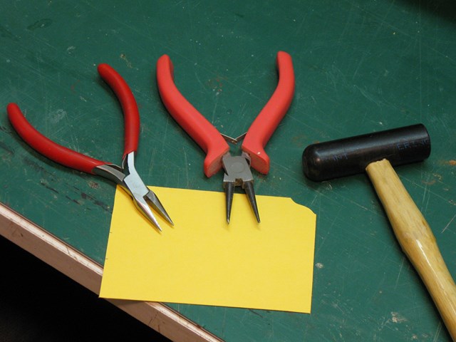
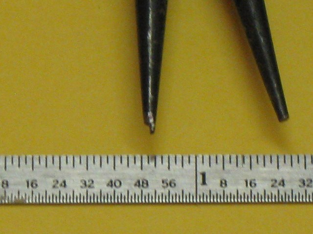
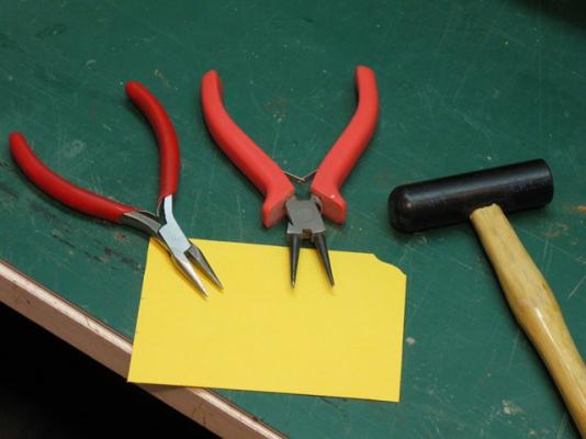
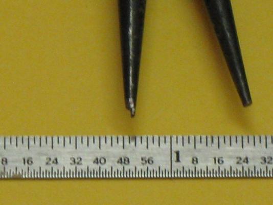
Thanks Paul. It’s nice to see you back on the forum. As for bending the brass I mainly use three tools. A pair of Jeweler’s pliers with a smooth clamping face so it does not mar the brass. A pair of round nose pliers that I modified by filing down one side to a smaller diameter. I made a hammer from a 3/4” diameter piece of delrin plastic. Bob
-
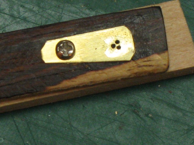
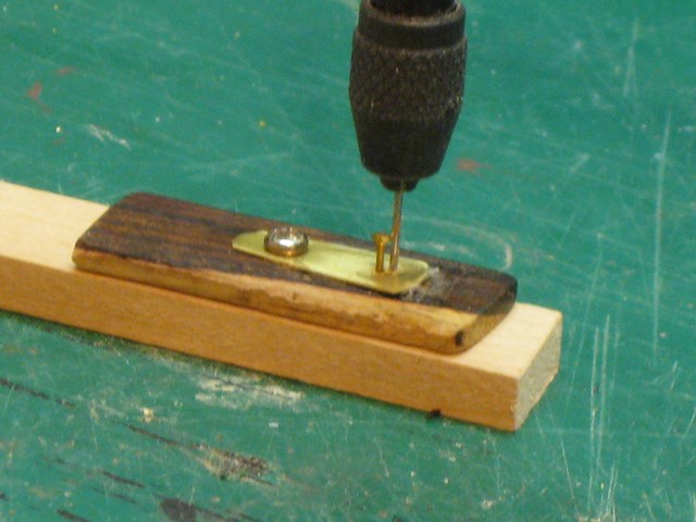
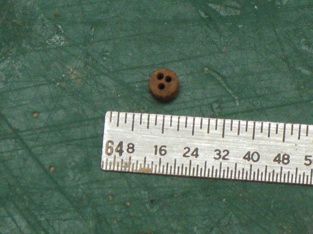
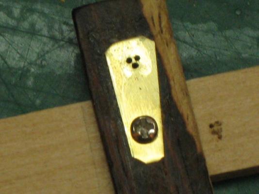
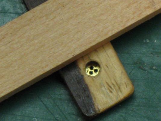
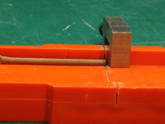
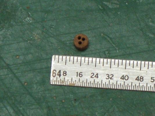
So now it’s time to attach the chain plates and deadeyes. To do that, I will need sixteen 1/8” (about 3mm) deadeyes. Yes, I could buy them but where’s the fun in that? Some time ago I remember seeing a jig a forum member had made to make deadeyes. So working from memory this is my, I think, third jig. You don’t want to see the first two. First on a .005” brass strip I used for a template, I drew a 1/8” diameter circle and located three .020” holes. My second try looked OK. I had a scrap of hard wood, (I don’t know woods but I think it is rosewood.) 1/16” thick, I drilled a tight fit 1/8” hole in it to hold the deadeye while drilling the lanyard holes. All this was mounted to a piece of scrap wood. The first wood I tried for the deadeyes was too soft and fell apart after drilling. So I turned a piece of straight grained walnut (I do know some woods) before my lathe quit, to 1/8” and it worked fine. Being held together by a single screw you drop in the blank, pivot the holder over the base and drill one hole. Then, I found out the hard way, put a pin in that first hole to hold the deadeye in place as you drill the other two holes. That’s it, and now I have to do it again. I need four .09” diameter deadeyes. Oh well. Bob


-
Thanks Keith.
-
Thanks Lawrence, Your Victory is coming along nicely also. I wish I had the room to try something like that. Sorry you haven’t received the drawings of the Stone yet. Hopefully before you finish the Victory. Bob
-
Sounds good. Bob
-
Walt, Sure sounds like you're set for a while. Good fun ahead. Bob
- 208 replies
-
- 1
-

-
- meridea
- repair ship
- (and 1 more)
-
“Oh yes and now I need to make a set of four hinges that are the same size.” Yes, yes, one is fun, four is work, but it's a beautiful hinge. Bob
-
Almost finished and looking great. Bob
-
I’ve seen single person rowboats that were oar powered R/C. It only took two servos. It will be fun hooking all those oars together. Bob
-
R/C ...WHAT TYPE OF GLUE SHOULD BE USED???
captainbob replied to Cap'n Rat Fink's topic in RC Kits & Scratch building
Mix epoxy or polyester resin 50/50 with alcohol and paint the inside with that. When the alcohol evaporates it will leave a thin layer of the epoxy which is more durable then varnish. Bob -
Very good. Very good. I needed that. Bob
-
What? Beveled panels on the hatch doors? Even Walter looks amazed. Beautiful job. Bob
-
Love the moon and stars. Bob
-
Popeye, I can just imagine a gaff head sailboat with that new picture from your wife painted on the sail. Great stuff. Bob
-
Ah Keith, now you’re getting into the physics and design aspects of ships. First, the placement of the masts and sails are a balancing act with the underwater shape of the ship. Let’s take the profile of the ship hull below the waterline, and let’s find the center of area of that shape. We will pretend that our ship is a wind vane and place the mounting post at this center of area point. Now it is time to place the sails. It becomes obvious that if the sails are too far forward the bow turns away from the wind and if the sails are too far astern the bow turns up into the wind. This same thing happens to a ship in the water. The locations of the sails have to be balanced with the underwater shape of the hull or the ship will turn into or away from the wind like the weather vane. It becomes a little more complicated than that when the sails have to be shortened in a storm and the captain needs to know which sails can be reefed and how much to maintain this balance. “Was this a developmental stage of the pilot boats evolution into schooners, aside from the hulls reshaping?” Every new design of any type of boat is an evolutionary experiment in that the designer really doesn’t know if the new design is good or not until the boat is in the water and sailing. Back again on sails, the wind pressure on a sail can be great. A breeze of 30 MPH produces a force of 3.5 lbs. per square foot on the sail. Concerning a jib sail this force is taken by the jib stay that tries to bend away from the wind. The force on the jib stay will lift the bowsprit right off the ship. So they tied the bow sprit down at the bow of the ship and placed the sampson post at the heal of the bowsprit to keep it from pushing down through the deck. The fore end of the bowsprit still lifted so they put chains under the jib stay location to hold the bowsprit down and also lines on the sides to stop the sideways motion. The sail plan you were looking at was the plan as the Lettie was when bought. I want to build it as it was originally. The diagram below shows the sails and rigging I will follow. If you still have questions feel free to ask. I love discussing ship and boat design. Bob
- 420 replies
-
- 10
-
-
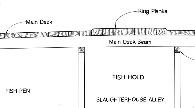
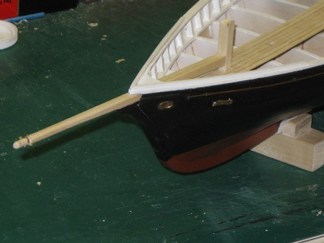
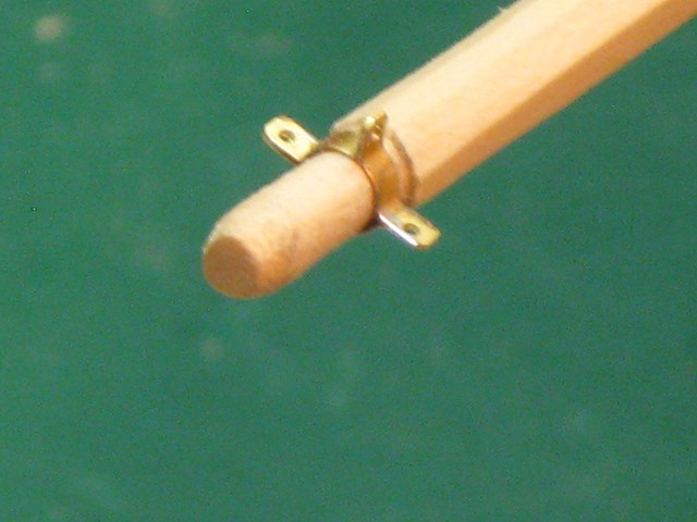
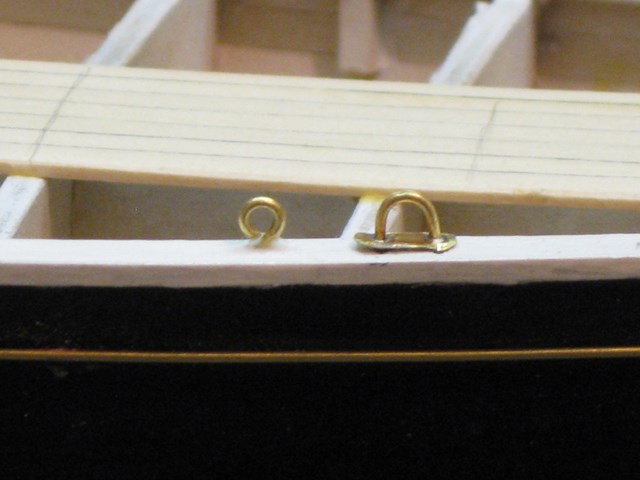
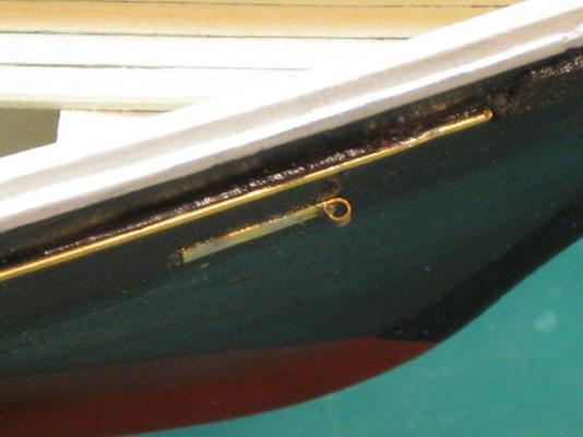
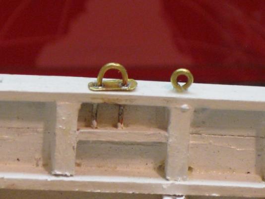
First off, thanks for all the good comments and the likes. Several of you made the same comments and asked the same questions. So let me answer you all together. The thicker planking is the king plank for added strength. And there would be added beams below the deck to help support the masts. I’m just surprise that the added thickness is above the rest of the deck. It seems that it would be a cause for stumbling. No, I’m not up to carving brass like Michael. Besides this model is 1:48 instead of 1:8. The brass piece on the bowsprit is made of .005” X .060” strip folded and soft soldered. My soldering iron has a 1/8” chisel point. I dab the joints with a liquid flux then place a small amount of solder on the flat of the iron and just touch it to the joint. The brass being so small it heats fast and sucks the solder up into the joint. Good guess, Michael. There will be two straps on the bow at about waterline. One will hold a line going to the end of the bowsprit the other will have a line going farther back where the second jib stay will fasten. I hadn’t considered supporting the planking along the edge but I probably should. Bob
-
All the color really makes it pop. Good job. Bob
-
Good place for the compass, right in the middle where it can be seen from either side. Bob
-
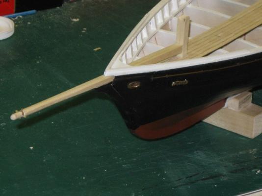
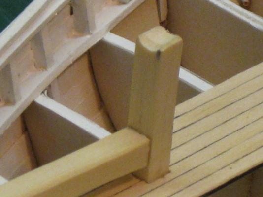
OK, if we’re through name calling we can go on. So moving right along. I want to do everything necessary to the hull before I finish the deck. I put down the seven planks that make up the king plank. Why it is raised above the other planks I do not know. The bowsprit is mortised into the sampson post and just set in place. I mounted the staples that nothing is attached to. Also the bowsprit chain plates (is that the correct name?) have been mounted. raised king planks. The sampson post doubles as the crutch for the jib boom.


- 420 replies
-
- 16
-
-
Help on wiring motor for sander project.
captainbob replied to Piperkronie's topic in Modeling tools and Workshop Equipment
Yes, solder the resistors to the pot as shown. They prevent there from being a dead short from 1 to 2 or 2 to 3 when the pot is at the end of rotation. The resistance is the minimum amount to protect the circuit. A greater resistance will affect the amount of speed you can control. Bob -
Xebec by mij - FINISHED - 1:60 scale
captainbob replied to mij's topic in - Build logs for subjects built 1751 - 1800
Nice eagle. Bob