
Supplies of the Ship Modeler's Handbook are running out. Get your copy NOW before they are gone! Click on photo to order.
×

albert
-
Posts
1,582 -
Joined
-
Last visited
Reputation Activity
-

 albert got a reaction from PeteB in HM Cutter Cheerful 1806 by Chuck - FINISHED - 1:48 scale - kit prototype
Very nice work.
-
 albert reacted to rafine in Granado by rafine - FINISHED - Caldercraft - 1:64
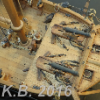
After completing work on the head, I wanted to do something less demanding (really, what wouldn't be ?}. I chose to do the two mortars. I used the kit's castings for the mortars, modified only by the addition of handles, as shown in AOTS. The handles were bent from wire. The mortar beds were also done with the kit parts, including eyebolts and the PE cap squares. I decided to show the mortars with one in a raised (firing) position and the other in a lowered (stowed) position.
I'm now moving on to start the remainder of the main deck detailing.
Bob
-
albert reacted to Chuck in HM Cutter Cheerful 1806 by Chuck - FINISHED - 1:48 scale - kit prototype
To make the bowsprit....start with a square stick of boxwood 5/16" x 5/16". The inboard section will remain square. The outboard side is rounded off and tapered. There are three square holes on the inboard sides. But these start out as round holes made on the drill press while the entire stick is still square.
There is also a sheave on the outboard end. The holes for this simulated sheave are also drilled while the stick is square.
Then the outboard end is measured and marked for the 7-10-7 ratios to make it an octagon. From an octagon it is then made round. There are many way to do this. Mini-plan...files...by hand....then rounded off on a lathe or even chocked in your hand drill.
Then I made it round...in my hand drill...and taperred it to match the plan while doing so.
Once that was done...the simulated sheave on the outboard end was detailed. I used a #11 blade to connect the holes and carve it out a little. Then mini-files were used to round off the simulated sheave. Later I will darken it with pencil.
The three inboard holes need to be made square...again there are many way to do this. I decided to just use my #11 blade to carefully square off the corners. The inboard portion will eventually be painted black.
The outboard end also has a metal band with four eyes around it. This was made from paper. You could use art tape or even brass if you wanted. Again there are so many choices. It was painted black and weathered so it looked differently than the wood elements painted black.
Then it was mounted in the hole at the bow and the fit tweaked. Once it looked good, the bowsprit step was slid onto the inboard end. You wouldnt be able to slide the bowsprit in position if the step was already glued in place. So this is a bit tricky. But soon after I was able to get it all in position and glued securely. Then I touched up the paint and cleaned it up.
Next up the long guns can be positioned....but I am unsure of I will add them. They will look very crammed in there. I will have to contemplate that for a bit.
-
 albert got a reaction from ggrieco in Young America 1853 by EdT - FINISHED - extreme clipper
Hi Ed your metal work is fantastic.
-
 albert got a reaction from Charlie1805 in HMS Naiad 1797 by albert - FINISHED - 1/48
here are some photos of the naiad in construction...
http://i.imgbox.com/adbOFtmU.jpg
-
albert reacted to Bluto 1790 in HMS Leopard 1790 by Bluto - FINISHED - 1:80 - 50 gun ship - PoB
Hammock cranes: Phase 2.
While I'm deciding whether to fit the port side fore channel before or after the foredeck hammock cranes, I made a start on the starboard waist cranes.
While I had to fit the foredeck cranes individually, I was worried that I wouldn't make a very good job of fitting the others while trying to keep them all vertically parallel to each other as well as being equally spaced . . . so I decided I would try to fit the 7 waist cranes as a single unit by soldering them onto a base plate which could then be taken to the ship and fitted as one unit.
I cut a 5mm wide strip off a sheet of 0.005 inch (0.125mm) brass shim and soldered the cranes on to that >>>
In that photo above, the soldering looks much worse than in reality. In any case, when blackened, the soldering is almost invisible and it will be completely hidden once the netting is fitted. >>>
When I was soldering the 'legs' on to the foredeck cranes I found it very tricky trying to get these tiny parts stuck together (and not burn my fingers at the same time) so I made up a very simple clamping device.
Getting these 7 cranes soldered vertically on to the base plate for the waist was also going to need some sort of jig. . . and that's what I came up with --- "some sort of a jig".
From some scrap material, I concocted what must be the most crude jig ever seen by mankind! . . . but it worked perfectly.
Have a look . . . (please try not to laugh.) >>>
In the photo above, the brass base strip is held securely against the fence, and down on to the melamine base by the sliding 'clamp' on the right.
In the next picture the crane is held vertically in the slot that is part of the fence, and is being held securely by the sliding wooden 'clamp' on the left. This 'clamp' has a 1mm notch cut into the end that makes contact with the crane in order to prevent the crane from moving to the left or right.
Once clamped like this I have 2 free hands with which to concentrate on soldering . . . as well as not burning my fingers! >>>
This 'jig' (is it OK to call this thing a 'jig'?) will work for the other waist cranes as well as the cranes for the poop & Q/deck rails, but as the cranes aren't at 90 degrees to the poop side rails I'll have to adjust the vertical slot in the fence to being slightly off vertical . . . and I'll have to do that twice as each side is a mirror image of the other, so what works for starboard won't work for port.
-
 albert got a reaction from mtaylor in Young America 1853 by EdT - FINISHED - extreme clipper
Hi Ed your metal work is fantastic.
-
albert got a reaction from ggrieco in Dunbrody by Mahuna - FINISHED - 1:48 - Cross-Section - Irish Famine Ship
Frank very very nice work.
-
albert got a reaction from mtaylor in Dunbrody by Mahuna - FINISHED - 1:48 - Cross-Section - Irish Famine Ship
Frank very very nice work.
-
 albert got a reaction from Omega1234 in Dunbrody by Mahuna - FINISHED - 1:48 - Cross-Section - Irish Famine Ship
Frank very very nice work.
-
 albert got a reaction from Elijah in Dunbrody by Mahuna - FINISHED - 1:48 - Cross-Section - Irish Famine Ship
Frank very very nice work.
-
albert reacted to Mirabell61 in SS Kaiser Wilhelm der Grosse 1897 by Mirabell61 - FINISHED - scale 1:144 - POF - first German four stacker of the Norddeutscher Lloyd line
A little update...
fitting in of the aft mast and setting it`s rake...
cleats, bollards and hydrants for promenade deck...
trial to brush paint the deck furniture (slats of the benches only...
Nils
-
albert reacted to Mahuna in Dunbrody by Mahuna - FINISHED - 1:48 - Cross-Section - Irish Famine Ship
Part 46 – TopGallant Rails
The topgallant rails are 3 inches thick (1/16 on the model). I decided to also make them from a single piece of stock for simplicity. The curve of these rails was taken from the main rails before those rails were installed.
The topgallant rails are supported by a large number of oddly shaped stanchions. These stanchions appear to be above each of the main stanchions, plus additional topgallant stanchions between these.
I think these topgallant stanchions will be a striking part of the model, so I wanted them to stand out. On the replica ship these stanchions are painted white, so I decided to use holly for them.
Since there are so many stanchions (52 in all) I used 4 pieces of holly glued together with ambroid glue, so that 4 were made at a time.
A piece that was slightly larger than the width of a stanchion was parted off, and a drawing of a stanchion was glued to it.
The bottom and the straight side were shaped using the disk sander, and the curved side was cut on the scroll saw. These stanchions are so small there was no opportunity to do any final shaping, so accuracy in cutting the curved side was critical.
The set of stanchions was then parted off, leaving a little height on the stanchions for shaping later.
The set of 4 stanchions were then immersed in acetone (in a closed container) for a few minutes to dissolve the glue.
This process only took a couple of hours, since making 4 stanchions at a time reduced the amount of effort involved.
Once all of the stanchions were manufactured, installation could begin. A line had been drawn on the edge of the main rail to indicate the location of the outside edge of each stanchion. The topgallant stanchions that would be located over the main stanchions were installed first.
Since there was no opportunity to clamp or pin these stanchions due to their small size, a different gluing technique was used. Glue was painted on each surface with a fine brush, and was left to set up for a few moments. The stanchions were then pressed in place and left to dry. This approach made the PVA glue act like a contact cement, and the stanchions were securely held in place.
Once the glue had dried sufficiently the bulwark planks were installed. As with the other bulwark planks, these were first marked, pre-drilled, and copper simulated bolts were installed prior to installing the planks. Alligator clips were used to clamp these planks in place.
None of the stanchions came loose during this clamping – proving the strength of the bond described above.
After all of the planking had been installed the remaining stanchions were then installed by gluing them to the main rail and to the bulwark planking.
The tops of the stanchions had been left slightly oversized. This was reduced to the final height by filing the stanchion down to the top of the bulwark planks.
The topgallant rails were then installed by gluing to the top of the stanchions and the top edge of the bulwark planks.
The replica ship has a piece of molding located above the scuppers in the area of the chainplates.
This molding was created by parting off the shaped edge of a piece of extra main rail stock, and was glued in place.
The railings are now complete. I especially like the effect on the unfinished starboard side – it no longer looks as rough as it has.
Now that the rails are finished I can turn to the details on the main deck itself. The hatch coamings and planking need to be done before the chainplates and deadeyes can be installed.
Thanks everyone!
-
albert reacted to EdT in Young America 1853 by EdT - FINISHED - extreme clipper
Young America - extreme clipper 1853
Part 176 – Whisker Booms
After a couple weeks on my favorite beach – one passed by Young America on her last fateful voyage – I have now returned refreshed and ready for the fall modeling campaign. The whisker booms were completed just before we left.
Whisker booms were iron extensions to the catheads that served as spreaders for the chain jibboom and flying jibboom guys. The first picture shows the installation of these fragile-looking members.
The whiskers extend about 5 feet from the ends of the catheads and are bolted to the after sides. Each has formed cleats on the top face through which will pass the chain guys.
The whisker booms were made from hard brass plate and were shaped by hand methods – sawing and filing. In the next picture a jeweler's saw with a fairly wide blade is being used to cut the inner line of the end cleat on the pair of booms.
Apart from these initial cuts, each boom was shaped individually. The next picture shows one finished boom and one in progress.
To be sure these would smoothly pass the chain guys they were tested as shown below with some of the correct-size chain.
In the next picture the port boom is held in place with a clamp while the run of the chain guy is being checked.
The guys will obviously be installed later when the bowsprit is installed and rigged. The next picture shows the port boom temporarily bolted to the cathead.
The bolts were silver-soldered into the booms before blackening, then rounded off and cut to length. The bolts were then CA glued into drilled holes in the cathead.
The last picture shows the finished boom on the port side.
Ed
-
 albert got a reaction from Martin W in HMS Atalanta 1775 by tlevine - FINISHED - 1:48 scale - from TFFM plans
Hi Toni, magnificent work.
-
-
albert reacted to yamsterman in WASHINGTON GALLEY by yamsterman - 1/48 scale - POF
HI ALL
A VERY QUICK UPDATE.
THE WALES ARE NOW ON!!!!!!!!
HOLE FOR THE RUDDER ALSO CUT IN THE COUNTER.
LOTS OF CLEANING UP ON THE WALES AND FRAMES TO DO.......WORKING WITH EBONY IS A MESSY BUSINESS.
CLAMPS HAVE FINALLY BEEN FINISHED...WILL USE THESE WHEN PLANKING ABOVE THE WALES...NEXT JOB.
CHEERS FOR NOW.........MICK
-
albert reacted to yamsterman in WASHINGTON GALLEY by yamsterman - 1/48 scale - POF
HI ALL
WALE STRAKES ARE IN THE PROCESS OF BEING FITTED.
EASY ONES ARE ON......JUST WORKING ON THE AWKWARD SO AND SO'S.
EBONY STRIP BEING EDGE BENT TO MATCH THE SHEER CURVE OF PLAN.FIRST STRAKE IN PLACE.PIECE OF EBONY HEAT BENT 3 MONTHS AGO AS A TESTFINAL STERN PIECE..WITH A TWIST!
-
albert reacted to yamsterman in HMS Naiad 1797 by albert - FINISHED - 1/48
hi albert
belissimo!! wunderbar!!! magnificent!!!!
beautiful workmanship and a stunning result so far.
looking forward to lots more.
thank you
cheers....mick
-
 albert got a reaction from Captain Poison in L'Amarante 1749 by giampieroricci - FINISHED - 1:30 - French Corvette
Very very nice work Giampiero.
-

-


-
-
albert reacted to wyz in HMS Naiad 1797 by albert - FINISHED - 1/48
Some things in life never change, like the quality of your workmanship on this model. Beautiful, as always!
Tom
-
albert reacted to archjofo in La Créole 1827 by archjofo - Scale 1/48 - French corvette
Hello,
many thanks for the nice comments.
It continues with a short update: