

jud
-
Posts
1,171 -
Joined
-
Last visited
Content Type
Profiles
Forums
Gallery
Events
Posts posted by jud
-
-
Imperial was fine growing up, but did not like the fractions even if working with them is not a problem to me. Then I learned about using decimal feet, which is my preference today, like it for the same reasons noted about the advantages of the metric system, base 10. Have no trouble with metric other than today when working on equipment when both metric and imperial sizes are use for fasteners on the same machine, autos being the worst, need two sets of tools to work on many of them. Converting some plans I received a few days ago to cad, WW2 design so feet, inches and fractions of an inch are used, they get converted to decimal feet quickly.
jud
-
Been looking at those combo Shear, Break an roller presses. Harbor freight has one for less than $400 that will shear and bend 30" wide 20 Gage steel, rollers are 1 1/2" so that is as smallest size you can roll anything, be it wire or sheet. Do know where one is that was never used. The owner passed on, but I have been avoiding descending on his widow like a vulture, but boy, he had a lot of nice tools and machine shop equipment.
jud
-
The answer will be different between those who served aboard, those who restored, visitor with interest or family member that had been aboard then the general public. The general public, having no personnel or family member with interest in the vessel will usually choose cheap and seldom will visit a museum ship unless they were killing time and she was handy. The ships I rode were WW2 vessels, all had been mothballed and returned to service when the need was there. Today's Navy should not sell any ship for scrap, if not needed, they should go through a yard period to bring them up to service standards and then mothballed with all the equipment, spare parts etc. aboard that are required to operate the ship, keep them whole and together for at least another 20 years, then consider turning her over to a museum, upgrading if the hull is sound, if not, strip her of equipment to be made available to the fleet, then make a reef out of the hull.
jud
-
That sure is a stealthy little boat.
jud
-
Is the Crain going to still be there tomorrow?
 Lightboy, USS Clark County LST 601
- thibaultron and EJ_L
-
 2
2
-
Liberty Ship SS Stephen Hopkins by schooner posted yesterday has a link ' http://www.globalsecurity.org/military/library/policy/army/fm/55-17/ch3.htm', showing cargo rigging. Illustration 3-17, Strain Angle of Falls is well worth studying. The physics has never changed from the early days of sail until today, some of the forces probably will come as a shock to some.
jud
-
In another accident, the NOTS RUR-4 Weapon Alpha rocket-boosted depth charge projector misfired, with one warhead falling back onto the 01 deck and killing a seaman below
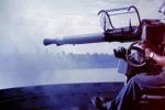
Called Hedge Hogs, the modernized Fletcher's had two mounts on the 01 lever just under and ahead of the bridge wing near where 40MM twins once resided, it was the gun crews from the 3" 50 Mounts between the stacks that maned the Hedge Hogs during ASW operations. The USS Ammen fired two racks of live Hedge Hogs during one exercise, 2 at a time, one Port and One Starboard, I was a crew member of the Starboard mount. One of those Hedge Hog's propelling charge was bad, it did not deliver a full charge and spewed unburned powder all over the deck. The Spigots Racks were rotated outboard, which allowed the the thing to fall outboard of the ship, didn't miss by much, but it missed. Being live, had it hit, it might have gone off in spite of the built in safeties in the fuze. I trusted those built in safeties then, learned later that they did fail. Had one fail when a 40 MM projectile exploded just clear the bore, WW2 ammo in RVN. The case was also split which resulted in broken the extractors. I shifted guns, a twin mt and only using one gun, and continued firing our support mission. You guessed it, USS Harnett County, the advar shows the gun mount, it was the right gun.
jud

-
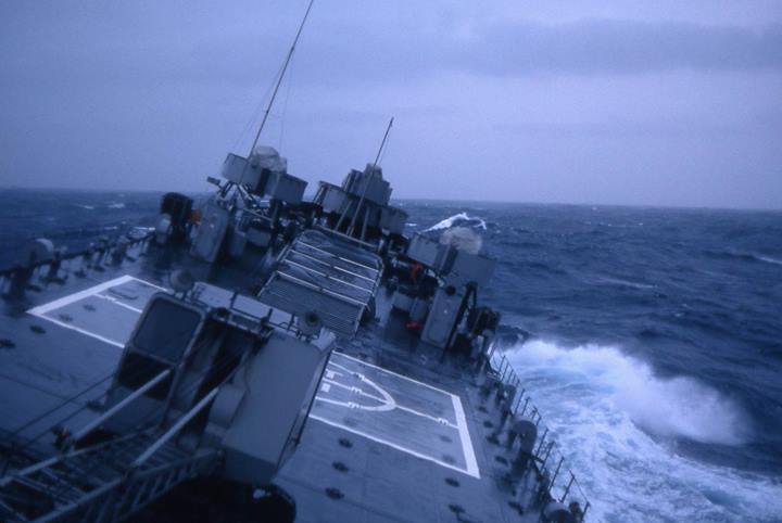
Harnett County LST 821, on a reef in the South China Sea, used as a Philippine military outpost in a increasingly disputed area. Advar is aboard her, 67 or 68 in one of the RVN delta rivers. Other ships I rode, USS Ammen DD 527 and USS Helena CA 75 ended up as scrap, Don't know what happened to the other 2 LSTs or the ships I was aboard for training.
jud
-
Never have seen a file card, 'Brush', for needle files or riflers, perhaps a small hand wire brush would work for small files. Have a couple for use on files 10" long or longer, work best if the file is chocked prior to using it, keeps small filings from being bottomed and held in the groves between the teeth. Filing away from the handle and then lifting the file for the return stroke will keep a file clean and sharp, if used on the material it was designed for. Have some old books, purchased from Lindsey Publishing, describing how blacksmiths made and hardened their own files.
jud
-
There would need to be an iron socket in the top of any wood post to receive the swivel pin from the gun. The fit needs to have some give in it which would allow for a hammer blow to develop, without a socket liner the socket itself would be enlarged. The cap was probably forged with the socket as an integral part and the top of the post fitted to it.
jud
-
You need something to tie your horse up with.

jud
- riverboat, davyboy, Captain Poison and 2 others
-
5
-
Good candidate for using your bondo corrected and cleaned up part to create a rubber mold, then a wax model. Might be able to take your wax model to your local Community College Art Dept and have a lost wax copy made. Your wax model and it's copy will be a true copy of every flaw and finish you allow. You can do it at home with low melting alloys, but using an art department with kilns that will handle brass you can upgrade from a Babbitt alloy.
jud
-
Anhydrous Ammonia is stored under pressure because it is gaseous at atmospheric pressure, containers may burst, but by itself will not explode. Years ago Aqua Ammonia was used for fertilizer and other things, went out of favor for farm use because of the mass. The last Ammonia I bought was in a liquid form, not under pressure and came in gallon plastic jugs, 4 to a case which was the minimum you could purchase and have shipped as hazardous material, that freight cost about 5 times more than the case of ammonia did. Needed it as a developer for my blue print machine, still have 2 unopened jugs left. Ammonia regardless of form is not an explosive or fire hazard but it can hurt or kill you if precautions are not taken, it displaces air and will form a cloud that burns your eyes and leaves you with no air to breath, the Aqua you can just move away from unless a lot is atomized quickly, the Anhydrous, being under pressure until released can burn you, 'actually frost bite', burn your lungs and eyes as well as displace your air. Every applicator I have been around is equipped with an emergency water eye rinse. Have used ag applicators to inject a lot of it into the soil as fertilizer, turns into nitrogen in the soil which can be made to explode in some forms but not in the soil as used for fertilizer. Those machines have a lanyard and valve used to pre-charge the system so skips aren't made when first starting from a stop, if not careful using it, you quickly learn about overdoing it as well as to keep the machine down wind if you can. If you need a small bit of ammonia, might try peeing on your board.
jud
-
I used a simple method for the boats made from 1" X 4" lumber and a saw. Required a Horse Trough, some stones and a careful stacking of those stones onto the deck of my boat, when it dumped them I knew the limit. A very reliable method unless I introduced some wave action and lost my cargo. Needed to spend some time retrieving stones from the bottom of the trough, for butt protection.
jud
-
Would be careful with cardboard, it's a paper product and will absorb fluids. Don't know what your finish is, but if it is not cured dry, there is a risk that the cardboard will draw enough of it to self glue itself to your model. Perhaps a wax coating or paint sealer on the cardboard might be good insurance.
jud
-
Carpenters of the days of Wooden Ships were well capable of making Gun Port Lids that fit, didn't need anything more that the taper or stair step type of seal to stop the Gun Port Lid from coming inboard more than the carpenters intended. Gun Port Stops, not gun port lid stops is the term used? I have been looking on all models and replicas for anything that would protect the area around the Ports from damage from rolling the gun back into battery, the carriage or the wheels need to be prevented from contacting the inside planking, matters not whether the gun is on a gun deck or quarterdeck, running the guns into battery at an angle or even square will do damage to the ship unless there is a sacrificial fender in place, I suspect that Gun Port Stops are those fenders and nothing to do with lids. Some gun carriages used a convex shape extending ahead of the carriage and wheels so the gun could be trained forward and aft using the convex part of the carriage to pivot around, that would keep the wheels from contacting the sides, but would still need something to protect the ship from damage from the convex end of the carriage. A lot of effort went into preventing damage to their ships and it rigging that could be prevented by the use of frapping, bumpers, leather wear points, etc., be out of character to allow the gun carriages and their wheels to cause preventable damage to the ship, Gun Port Stops perhaps.
jud
-
Ships pivot around the head from rudder movement, it is the stern that swings, that trait saved my ship 'the Ammen' from being cut in two during a collision, just enough time to start the swing, so the other ship slid down our Port side. 19 July 1960, USS Ammen DD 527, killed 11 injured 25.
jud
-
-
-
-
dashicat; Go to web.mit.edu/4.../1_lecture5.html and then click on, 'what is a moment', some good information there that should be of benefit to you and others wondering about forces and what it requires to keep things Static. An imbalance of force and resistance will result in movement unless restrained. 250# at the end of a cantilevered beam can create more force than many realize.
jud
-
dasacat; Been close to 50 years since I studied force vectors and bending moments, there are probably others much more qualified to do the math than me but I will do a very rough go at it, it should show the types of forces acting on the top of the rudder post created by using an unsupported cantilevered steering tiller. The easy bending moment would be the iron fixture at the end, going to use a weight of 150 pounds and consider the force as acting on the end of the 16 foot section of the wood tiller. 16' X 150# = a 2400 ft lb bending moment at the rudder head.
To make it easy will consider the force acting on the cantilevered tiller from it's weight acting at the mid point of 8'. So the weight of the oak tiller being 280 pounds concentrated at the unsupported midpoint the moments would be, 8' X 280# = a 2240 ft lb bending moment at the rudder head. Add those forces up, 2400 ft lbs + 2240 ft lbs = 4640 ft lbs of bending moment acting on the rudder post head, that way for the same reason we put long handles on wrenches.
What I did here is only a limited and rough calculation of the forces involved, it includes assumptions about where and what forces are involved but it should indicate the value of having support for the tiller. The modern replica may be using lighter and stronger materials, what is under the rudder post cover is unknown. Materials may change and lightening the load but the directions of the force vectors involved have not.
Keep in mind that my statics and strength of materials is very rusty and I'm not an Engineer.
jud
-
Good questions Franke. Keep in mind my first sentence in my post, #54, and the word perhaps. This was kind of an interesting exercise for me because of my experience with the effects of slack allowing movement that is then violently stopped, IE, the end of the rope, a proper hanging or a mechanical joint destroyed. Slack is something mankind has learned to avoid in the things he makes and slack in a steering system can be bad if it allows movement to happen that is then stopped suddenly. A man on the end of a tiller is a buffer absorbing the different forces acting on the rudder caused by wave action and the vessels reaction to it, 'constantly changing of the direction of forces'. Now if that man got tired of being beaten around and tied off the tiller, that would be fine as long as the lashing did not allow movement, allowing any slack would soon destroy the steering system because movement brought up suddenly, loosens, first connections then more.
That is why I adding Tension adjustment to my sketch, I do know that later steering systems using steering quadrants as rope guides placed adjusters on the tiller arms themselves.
Did not show any of the steering gear forward of the forward blocks that I did show, because that part of the system is rope running through stationary blocks to a stationary steering drum, none of which takes up or allows any more or less slack than already exists. Unless the drum is in a cone configuration, what goes on the drum, an equal amount comes off, so I didn't consider that part of the system a variable which I could reasonably manipulate.
The arc that the Tiller gear travels is another constant that we can only change by changing the length of the tiller itself, that arc is curricular, not a straight line, that creates a swing for any rope pulling on it from the side, can't change that. Then by mounting the blocks to the bulwarks at a height that keeps the vertical changes at a minimum that leaves us with only controlling the effects of the swing on the length of the lines on each side of the tiller to play with. We can keep that effect minimal by using the direction of the pull as the controlling factor. I chose two blocks to do that, why did I place them where I did? I drew a line from the end of the tiller through the end of the ark at the maximum swing of the tiller extended to the bulwark, I drew another line beginning where the first one began on the tiller through the maximum swing of the ark and extended to the bulwark. At the bulwark I now had two points related to maximum tiller swing, found the mid point between them for a third point. That third point represented the center of the change in movement of the tiller perpendicular to the arc, half of that movement being on each side of a line from the tiller to number 3. I placed two blocks at equal distanced from #3, that gave me a minimum perpendicular movement to the arc as the tiller was moved from C/L to its maximum outboard position. Doing it that way did keep the slack at a minimum that could be obtained without using a quadrant guide for the tiller ropes.
Is this the best way to do it, probably not? Do I think this is how it was done at the time, doubt it? This only represents an idea of how I might begin the layout if the rigging choices been mine to make, at that place and time.
Please keep in mind that I have not attempted to convince anyone or believe myself that my sketches represent how the Endeavour's steering gear was rigged, they only represent how I might do it. Others are welcome to add to or find errors with how my thinking might keep the slack at a minimum. I will especially encourage any documented enlightenment on this subject that might be offered or newly discovered.
I will defend the fact that movement allowed by slack, suddenly brought up will destroy anything over time.
I also must apologize that my communication skills prevented a much better explanation about my intent when posting those sketches. That shortcoming has lead me to be so wordy in attempting to clarify my intent and what I was saying, have been expect a chewing out for posting so much of what some must consider as drivel.
jud

-

Metric vs English
in Building, Framing, Planking and plating a ships hull and deck
Posted
wefalck, how do you get along with 2 bits, 4 bits or 6 bits ? Most in this country will give you a blank look if you start using that method of describing coinage, yet many were using that method when I was younger..
jud