DONATION DRIVE - SUPPORT MSW - DO YOUR PART TO KEEP THIS GREAT FORUM GOING! (91 donations so far out of 49,000 members - C'mon guys!)
×


Mike Y
-
Posts
1,557 -
Joined
-
Last visited
Content Type
Profiles
Forums
Gallery
Events
Everything posted by Mike Y
-

Looking for ideas for work area
Mike Y replied to Desertanimal's topic in Modeling tools and Workshop Equipment
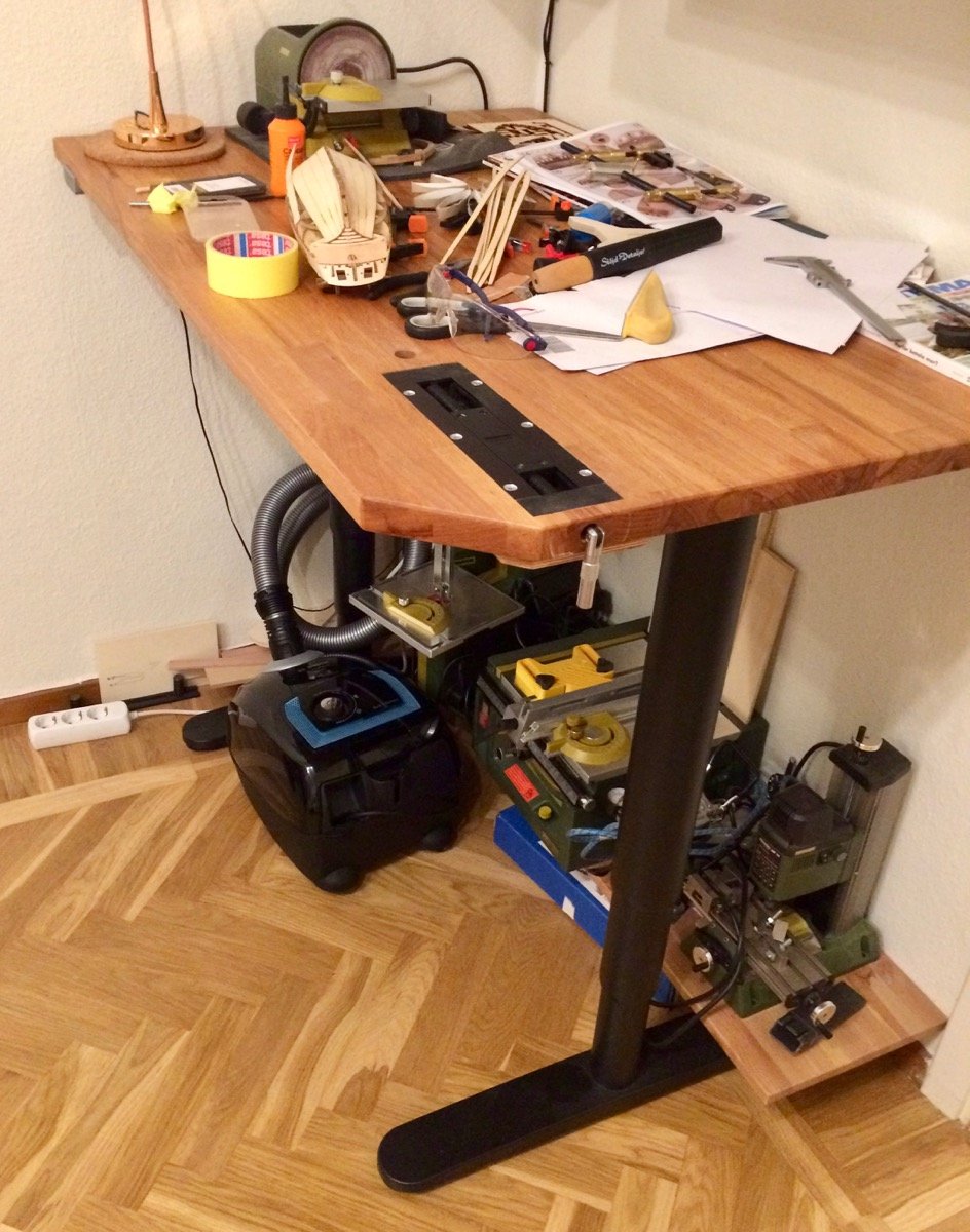
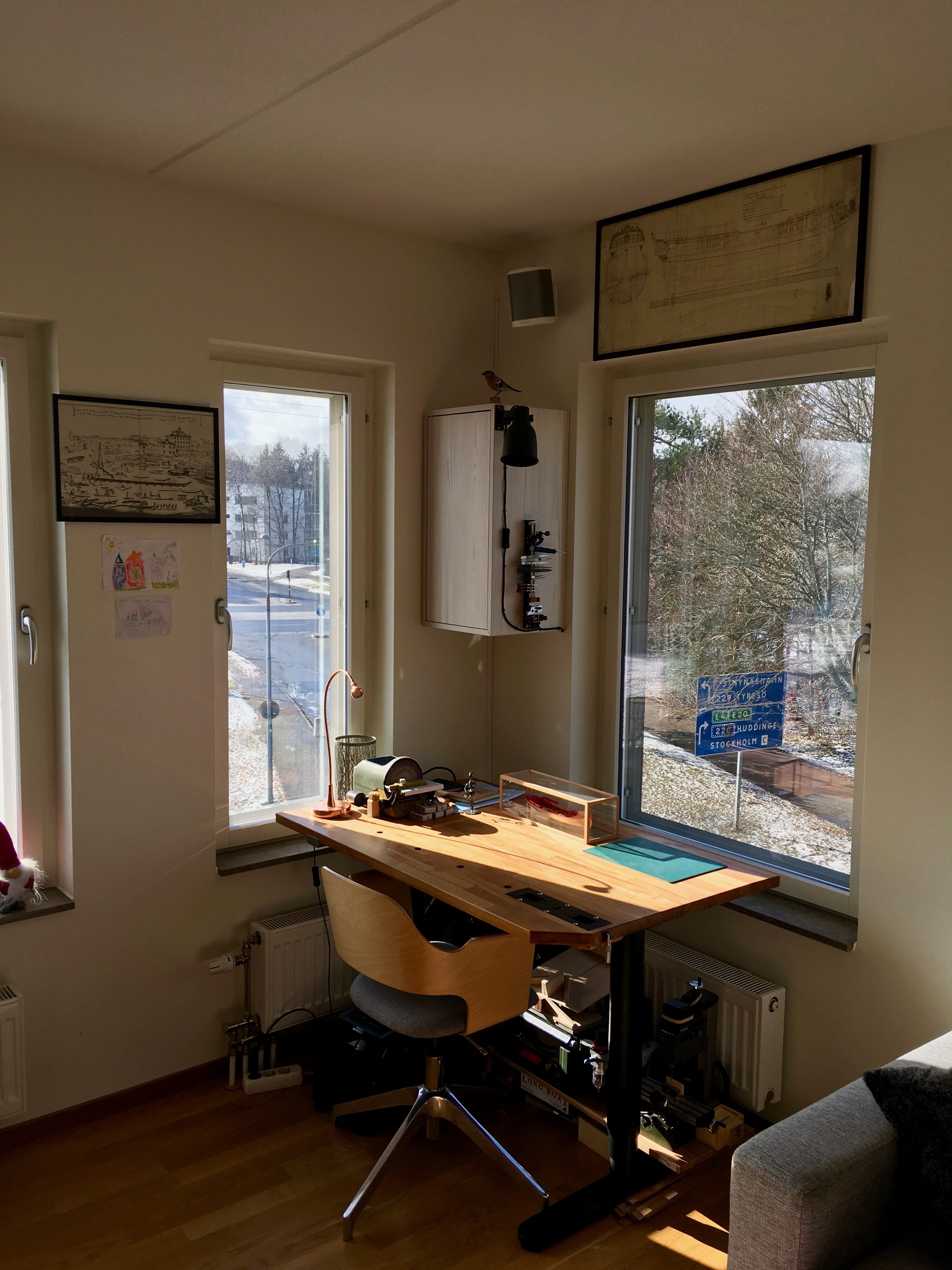
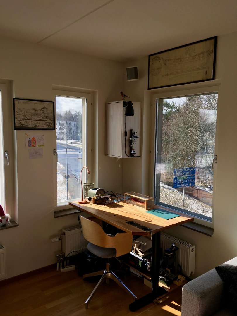
As always strongly recommend to buy an electrical lifting table, they are quite affordable nowadays with many companies on the market (including IKEA that sells frames separately). Replace a flimsy office tabletop with a sturdy solid wooden one - and you will end up with a fantastic build table that allows you to find a perfect height for any operation. I added an inset vise and peg holes into mine, the possibilities are endless. It is a relatively new "accessory" that is often overlooked, well worth the cost. I would avoid hammering mortise joint with a chisel on such a table, so it is not a full replacement for a workbench if you do a normal woodworking. But more than sturdy for all the modelling needs. Some examples of my setup (IKEA table frame, solid top cut to size of the working area, Veritas inset vise), very easy to customize it for your space.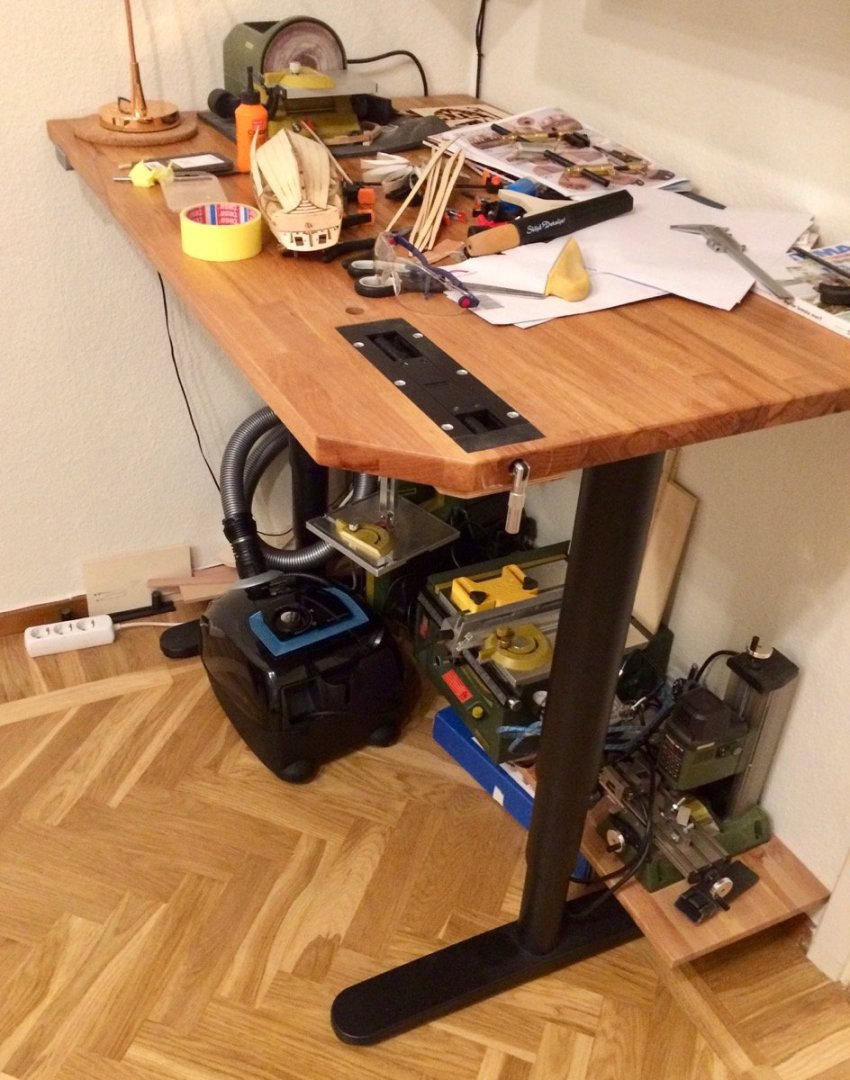

-
Glad to see your new build, subscribed with interest
-
Thanks Druxey and Alan! Sometimes a little nudge is all we need Toni, it feels similar to pear or box when it comes to hardness, definitely not soft. Holds an edge pretty well, but despite a clean geometrical shape the edge blurs visually due to the grain of the wood. But definitely an interesting wood to have in your palette. Will report in a couple of months on the way it ages!
- 968 replies
-
- 3
-

-
- hahn
- oliver cromwell
- (and 1 more)
-
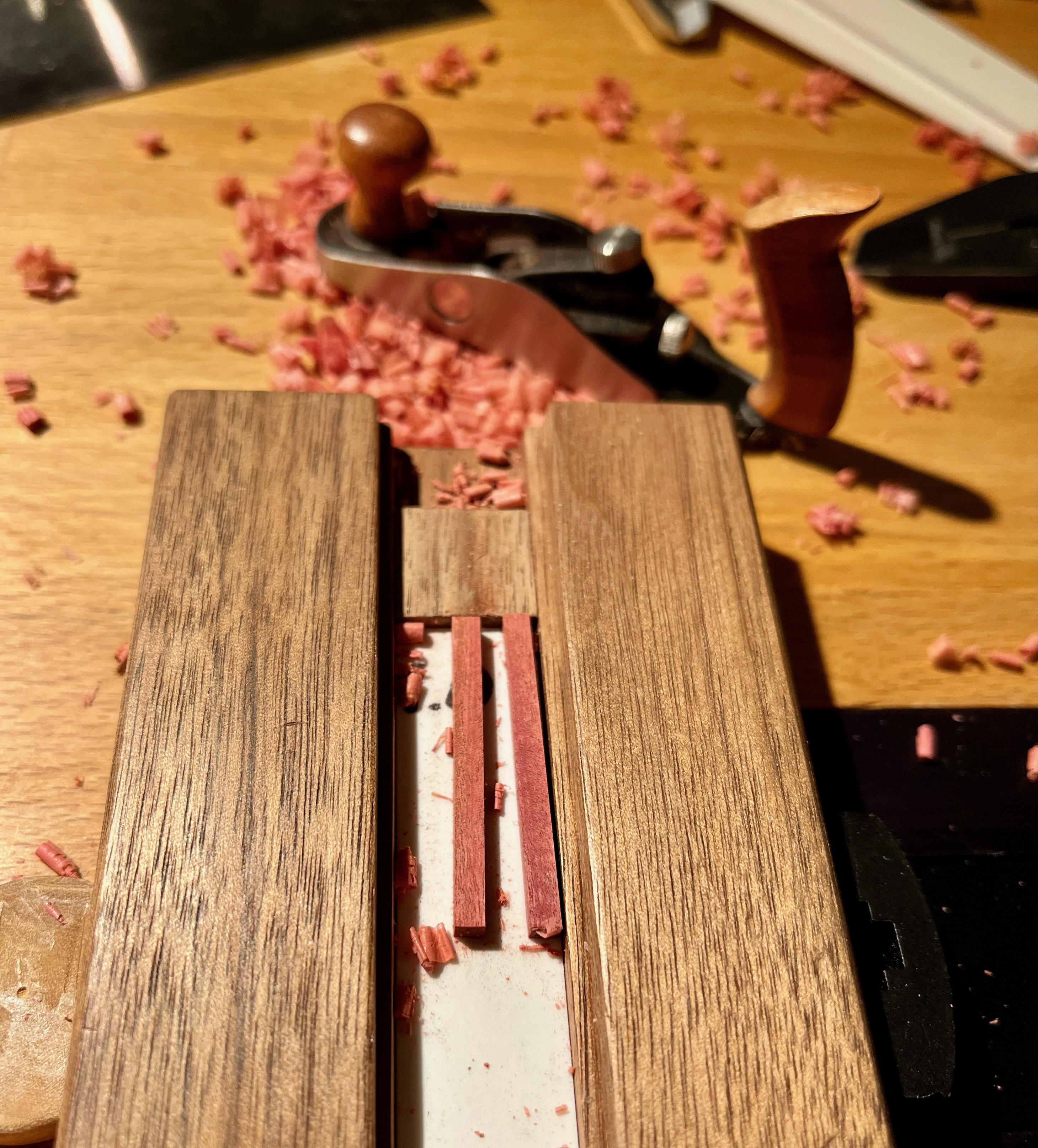
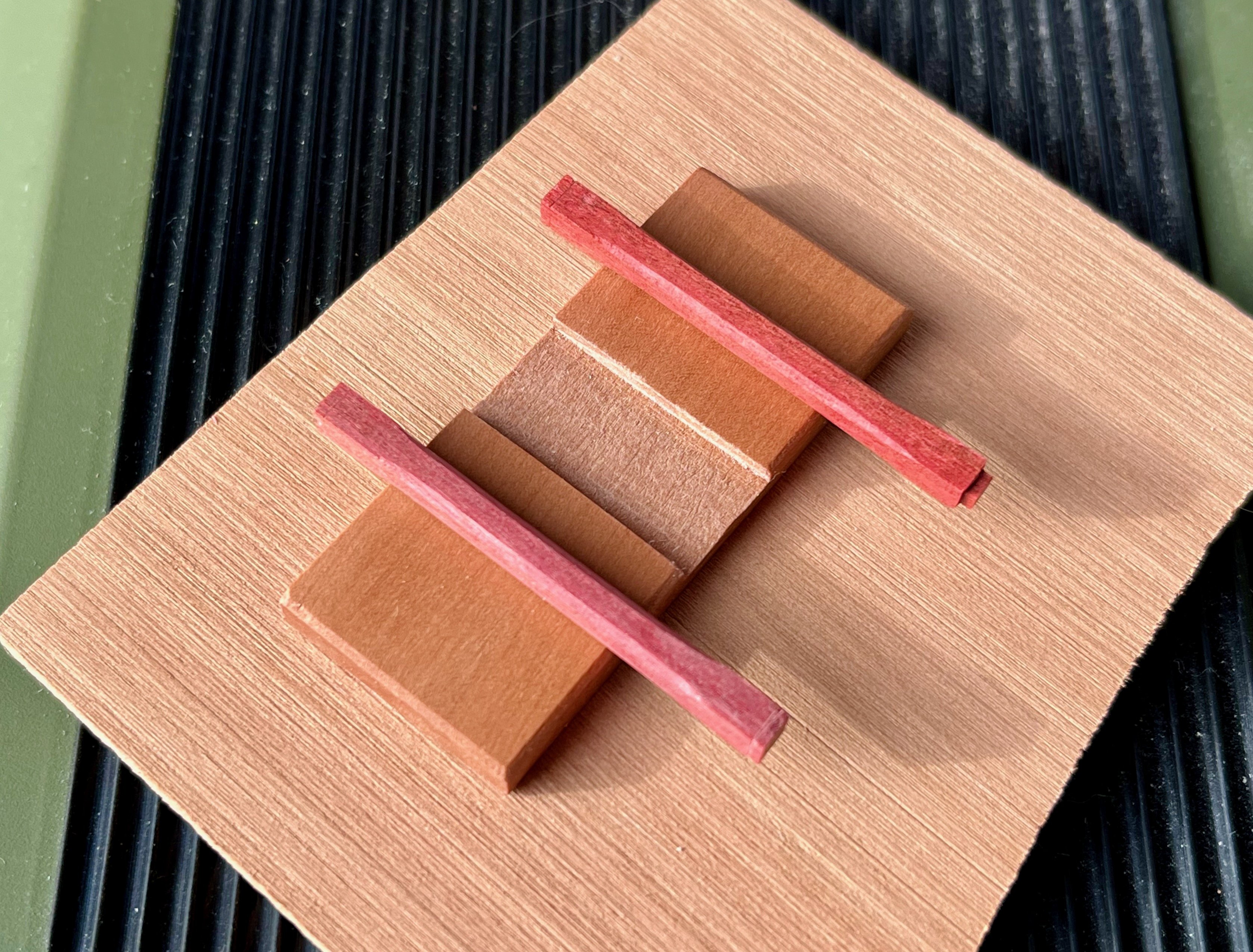
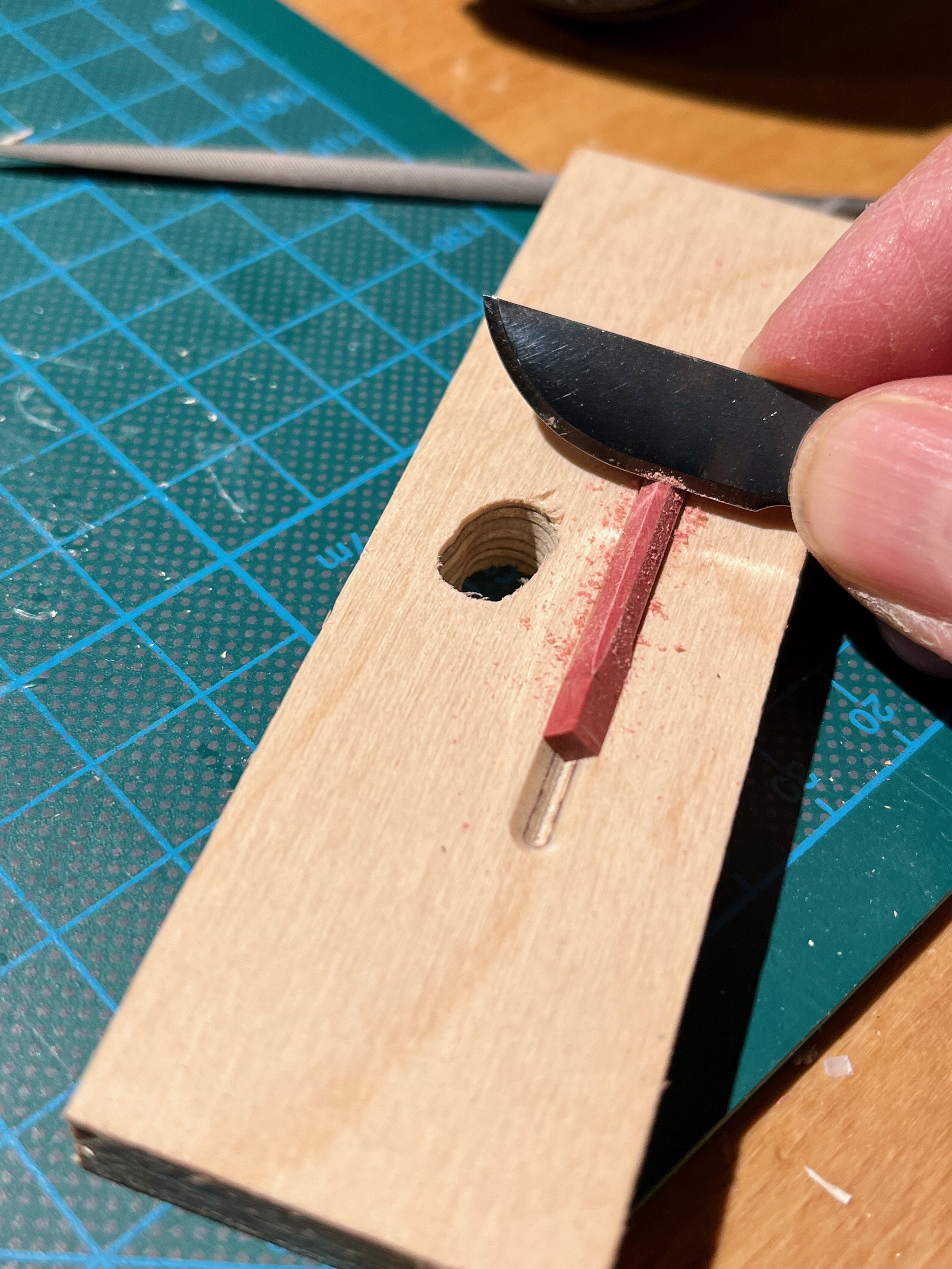
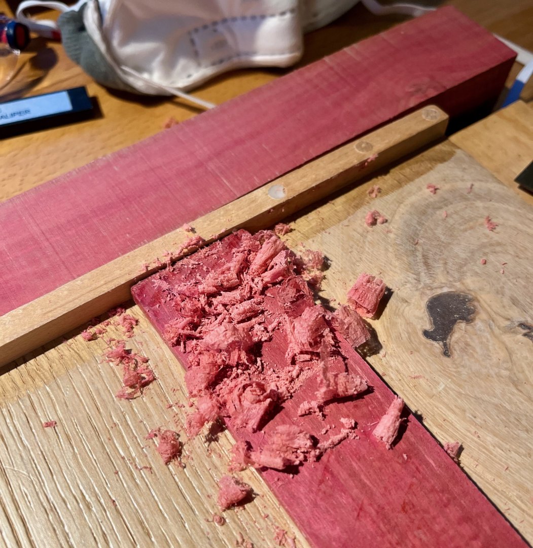
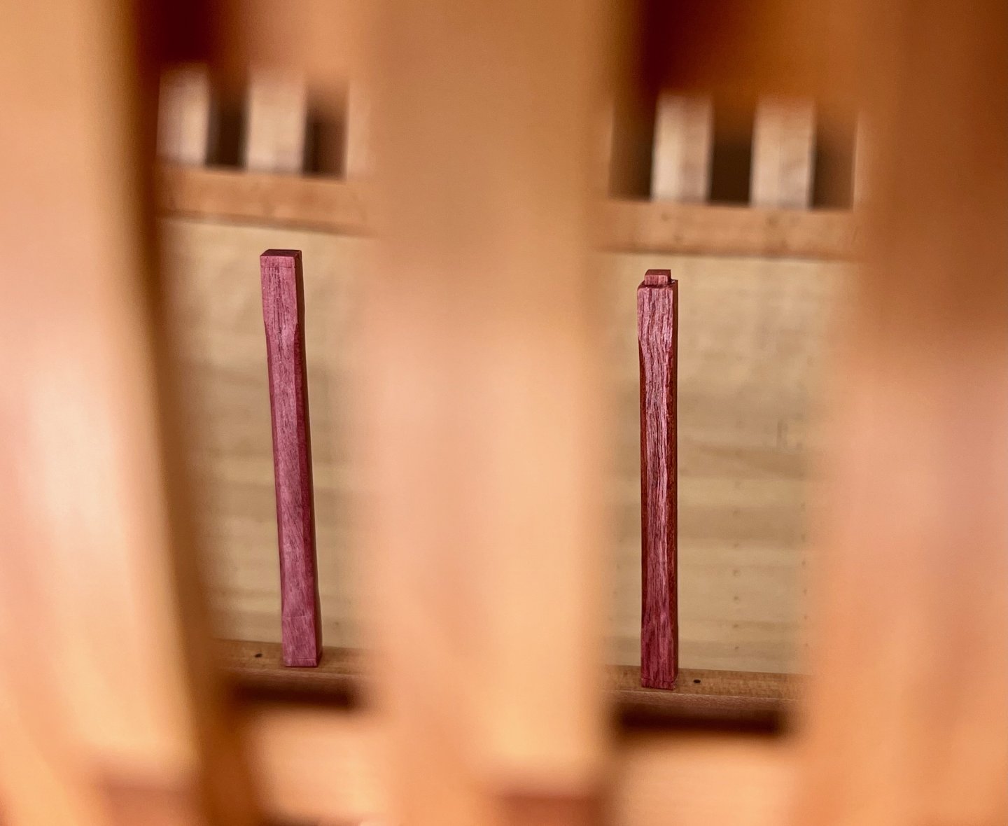
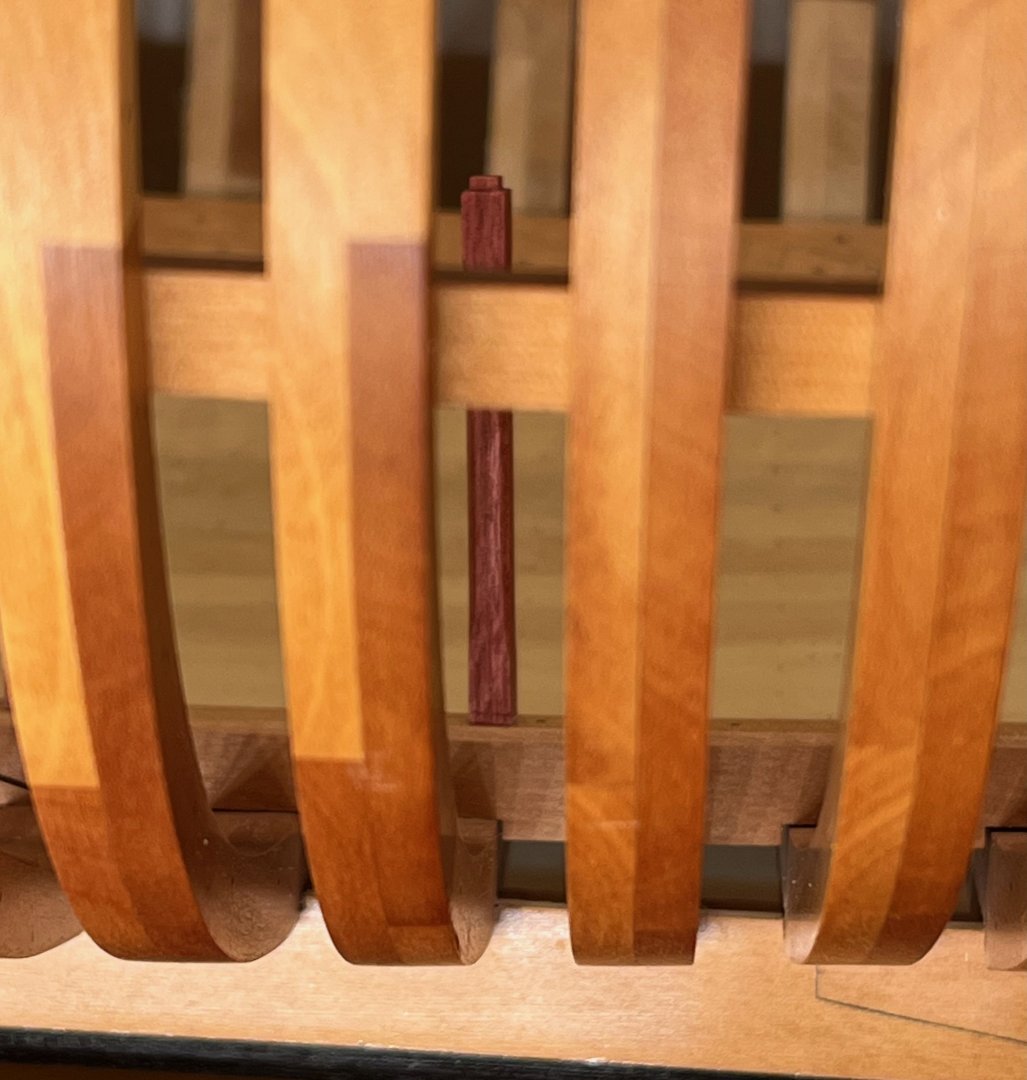
Experimenting with different woods for the Pillars in the Hold. Thought it might be a good opportunity to use Pink Ivory that I had in the stash for some reason. It is a very beautiful wood with pink shavings, indeed! A simple jig really helps to hold these tiny pieces when shaping. Scraping is a great way to get a smooth surface with a clean edge! Completed test pieces. The one with a tenon was finished with Osmo Polyx and the one on the left (with no tenon) has no finish. For colour comparison I made a photo on top of some pear parts (one finished and one - a rough sheet cutoff) Pink Ivory has a clearly pronounced grain resembling walnut, clearly out of scale. Though pillars in the hold definitely have a rough life I might still go with it, it might add an interesting accent deep in inside the hull when viewed from the side: As most of such woods it would likely loose its beautiful colour when exposed to UV, and would likely become brown-ish. I left these test pieces exposed on the table and will check them in a couple of months. Does anyone have any experience with this wood? What do think on the colour? I don't want my model to look like a clown car, but a bit of variety might not hurt


- 968 replies
-
- 12
-
-
- hahn
- oliver cromwell
- (and 1 more)
-
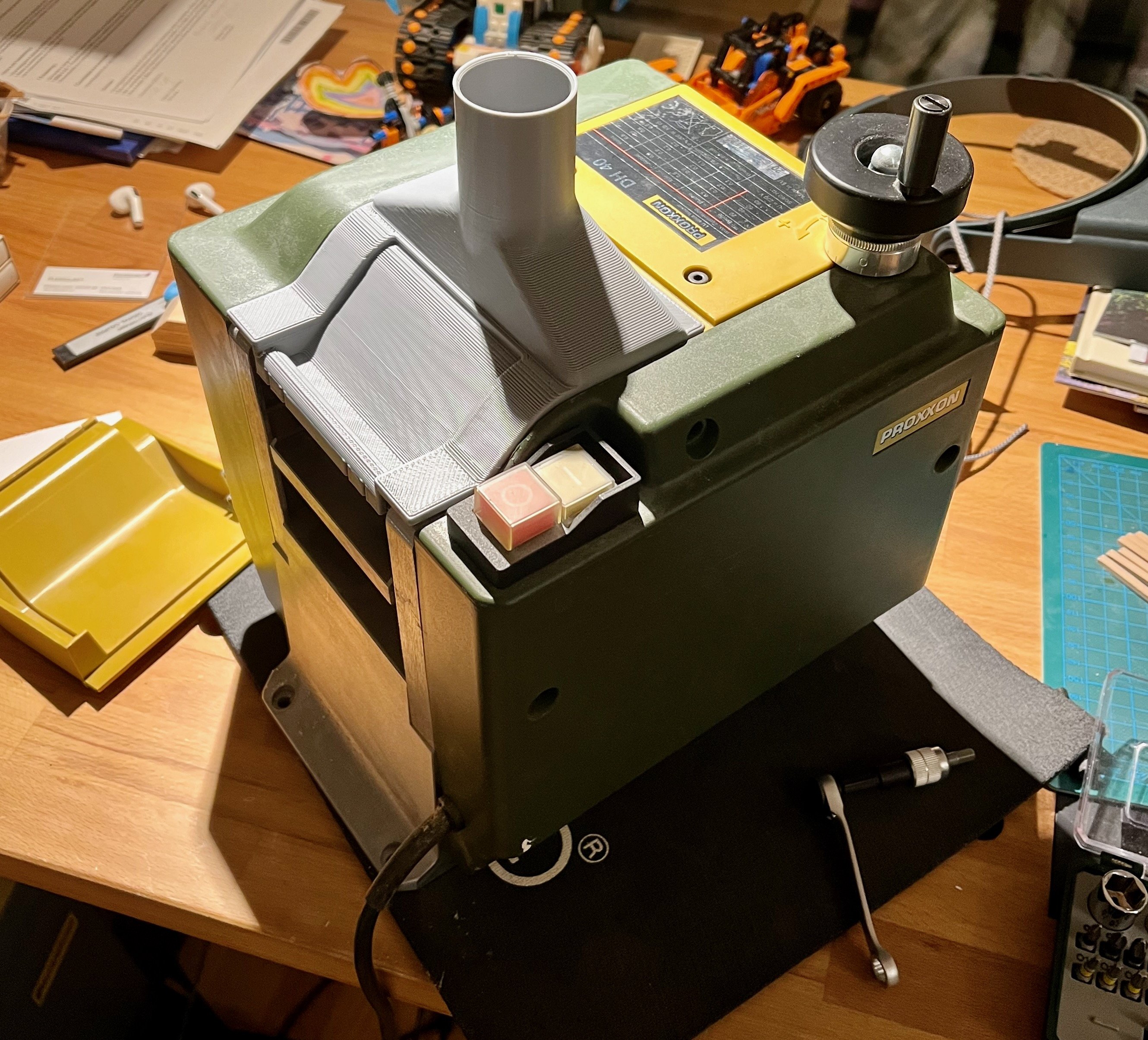
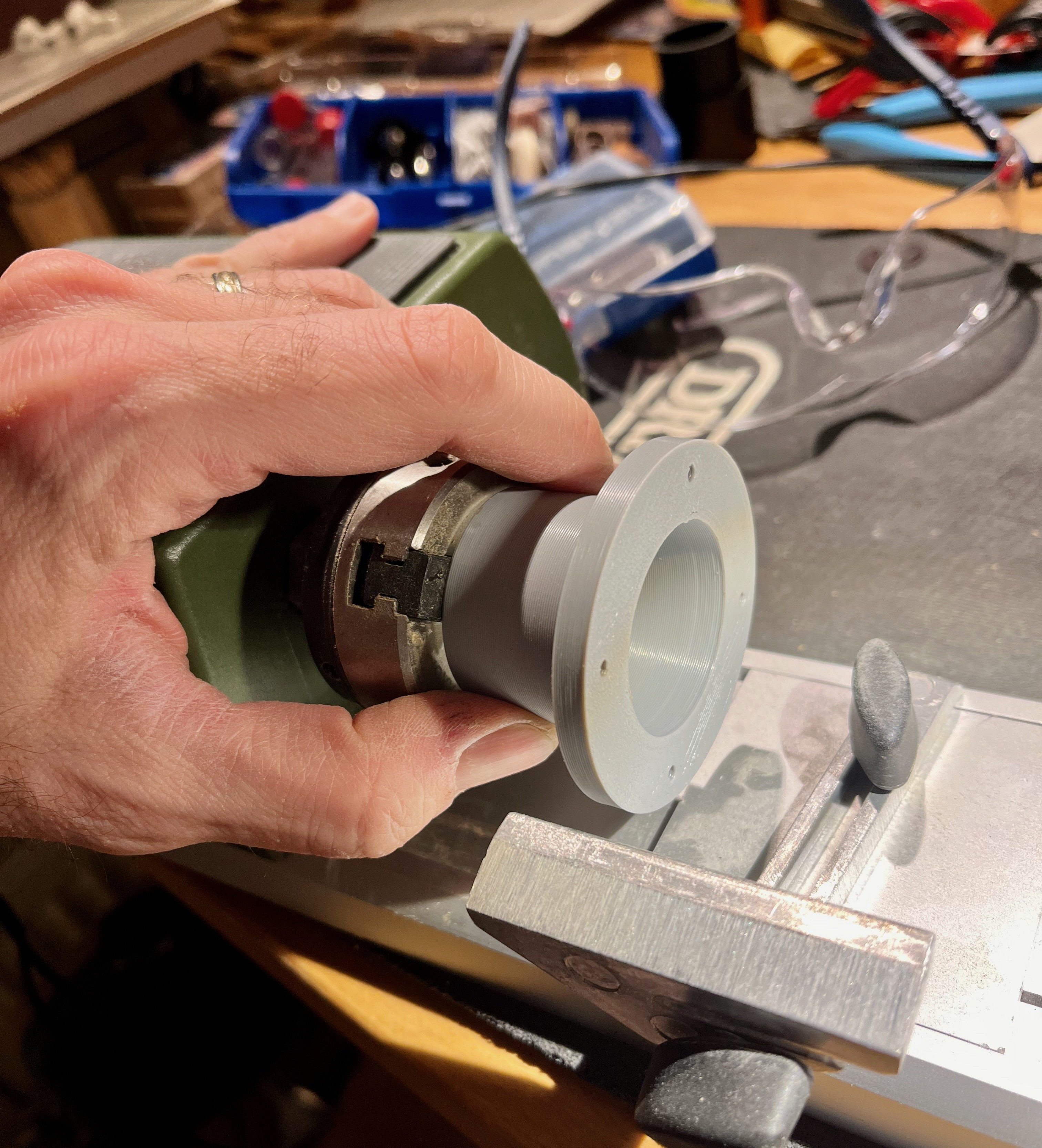
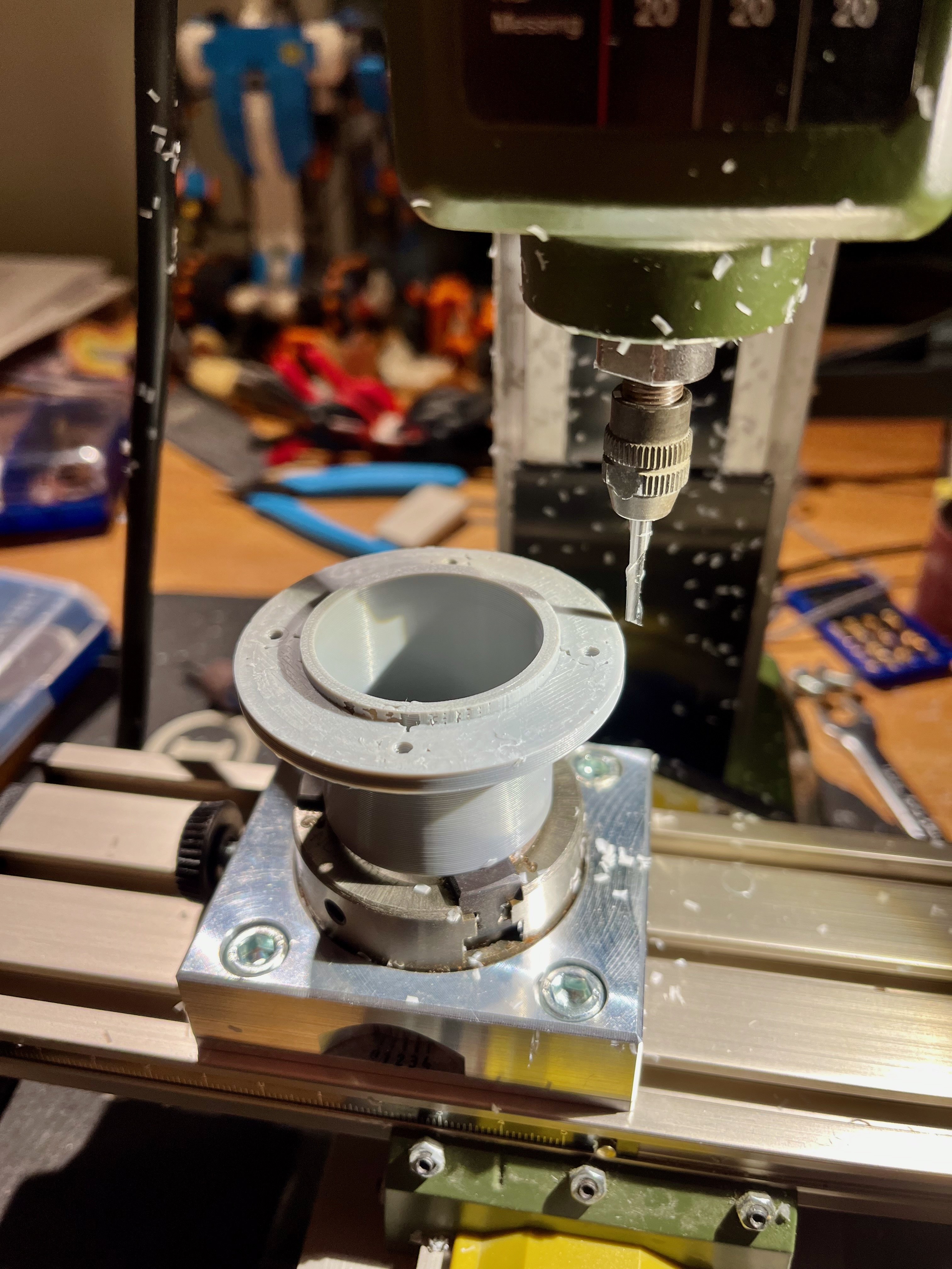
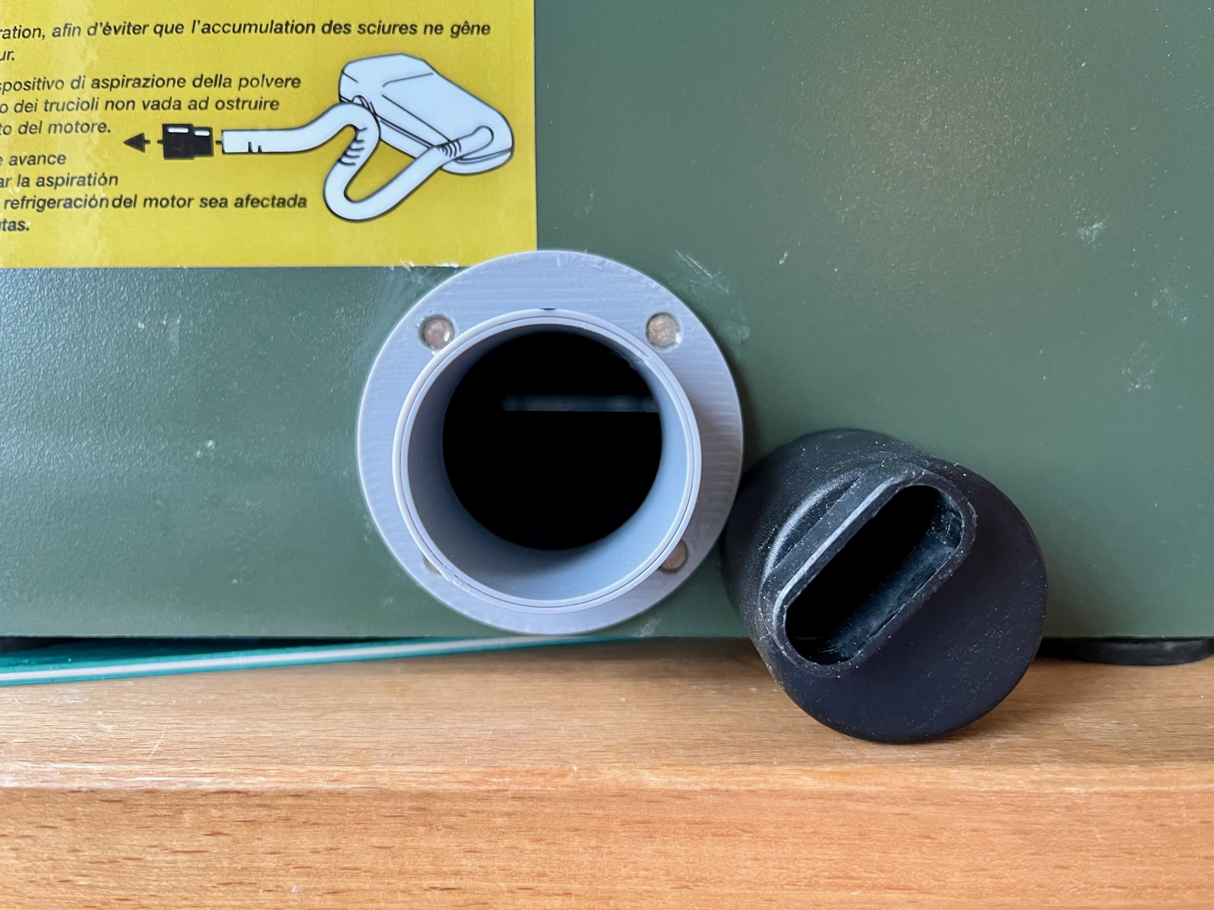
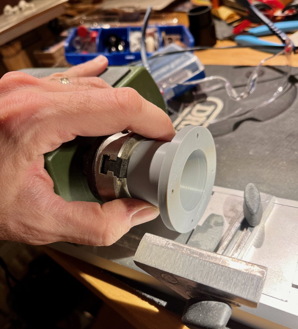
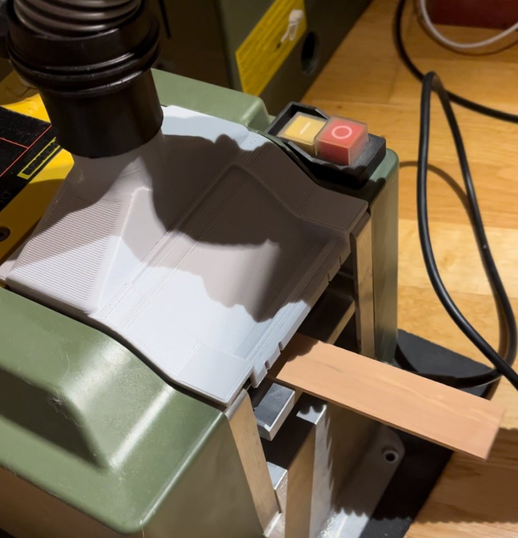
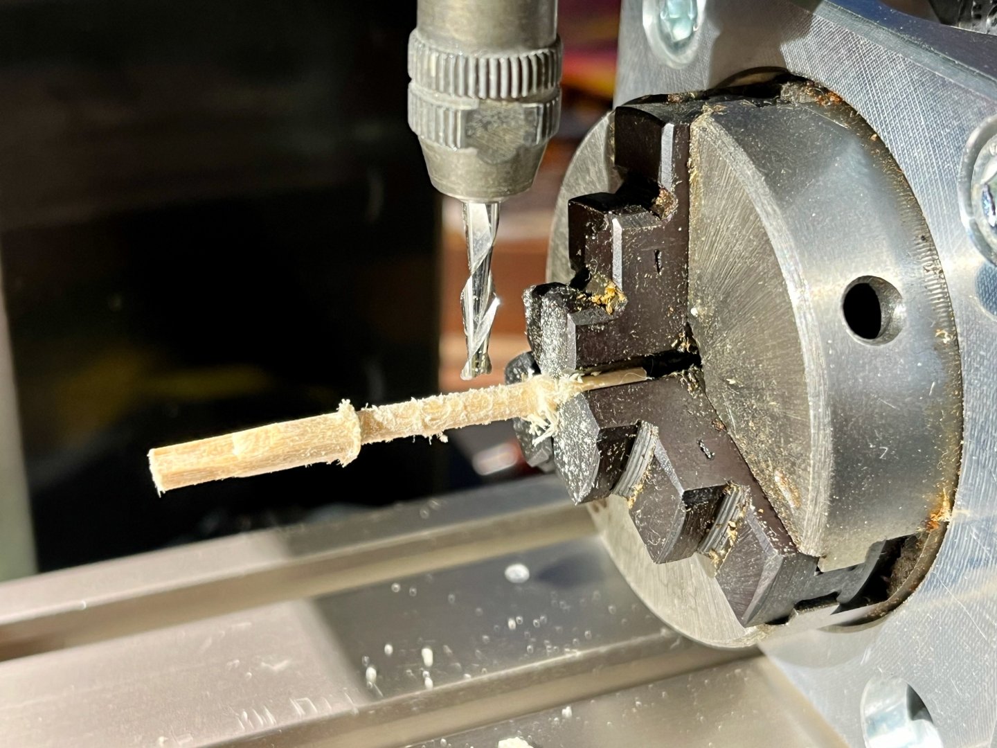
Tools update time! A friend printed some vacuum adapters for me The one for the planer works like a charm! Using the model from Oliver (see https://modelshipworld.com/topic/36705-suction-adapter-for-the-proxxon-dh40-for-download) Table saw received an update as well, the factory design is squeezing all the air through a narrow opening, generating a whistling noise louder than the actual saw. Now the opening is opened up, so the air can flow freely with a nice wind noise Link to the model: https://www.thingiverse.com/thing:4742157 Since I was short on space - decided to make the adapter removable, on magnets. To improve the connection a groove should be machined. It was impossible to clamp that soft plastic part on the lathe, it was just sliding out of the chuck So I milled it on the rotary table. A single flute mill makes a dramatic difference - the dual flute quickly jams with a blob of melted plastic, while a single flute cuts clear separated chips (that are light, fly all over the place and get stuck to everything, argh). The resulting performance is not as great as on the planer, some dust still escapes, but it is still a great improvement comparing to the default adapter. Can absolutely recommend both upgrades, especially the planer!


- 968 replies
-
- 4
-
-
- hahn
- oliver cromwell
- (and 1 more)
-
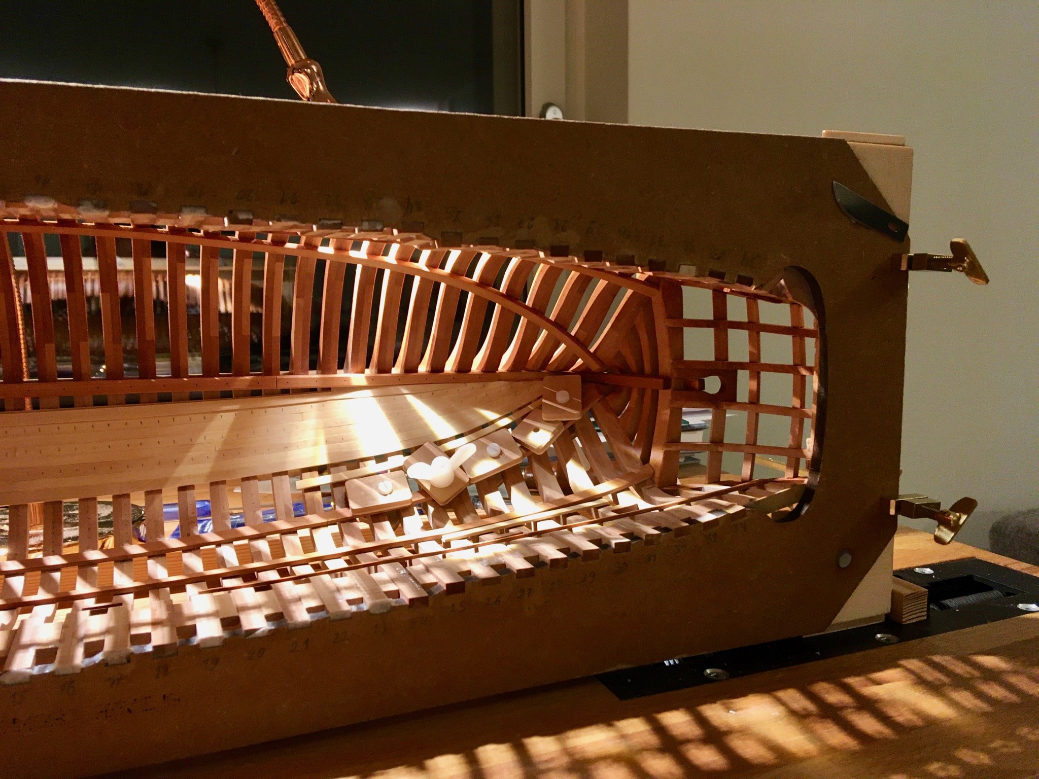
This definitely looks repairable (replacing only these particular frames), Isopropyl Alcohol is a common solution - it dissolves the glue and then evaporates without leaving a trace, allowing you to replace the parts without going for a full rebuild! Hope to see you back in this log after a well deserved break 😊
-
Nah, I just borrowed a phone selfie stick / tripod contraption from my teenage daughter and used a "photo timer" feature on the phone It is an essential item for her, how would you do some outdoor selfies and group photos otherwise?
- 968 replies
-
- 3
-
-
- hahn
- oliver cromwell
- (and 1 more)
-
Read some advices elsewhere on MSW on "3 inches from each side", but please learn from my mistakes - make a cardboard mockup in real size, put it on the future display location, etc. Trying to understand your display case dimensions from a CAD model or theoretical calculations is a path to failure, don't ask me how I know (my "aquarium" is 1.5x larger than envisioned )
- 452 replies
-
- 5
-
-
- cheerful
- Syren Ship Model Company
- (and 1 more)
-
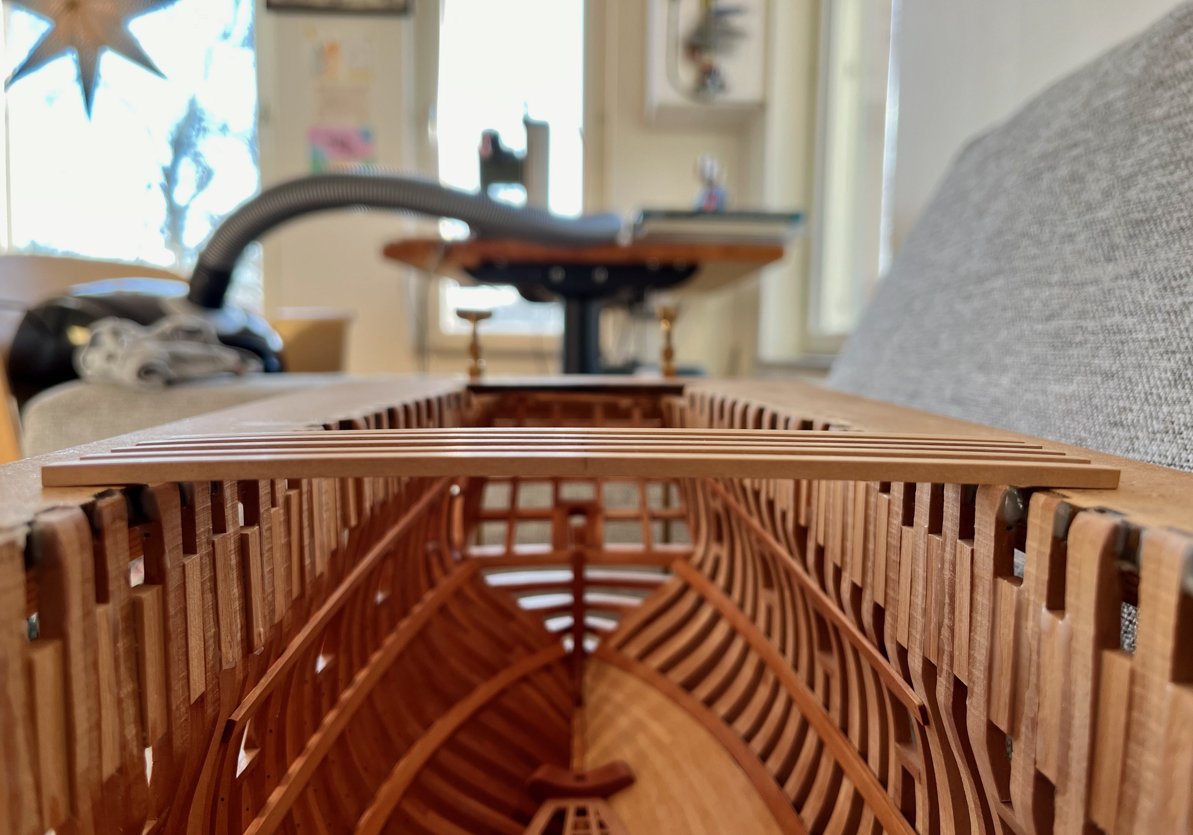
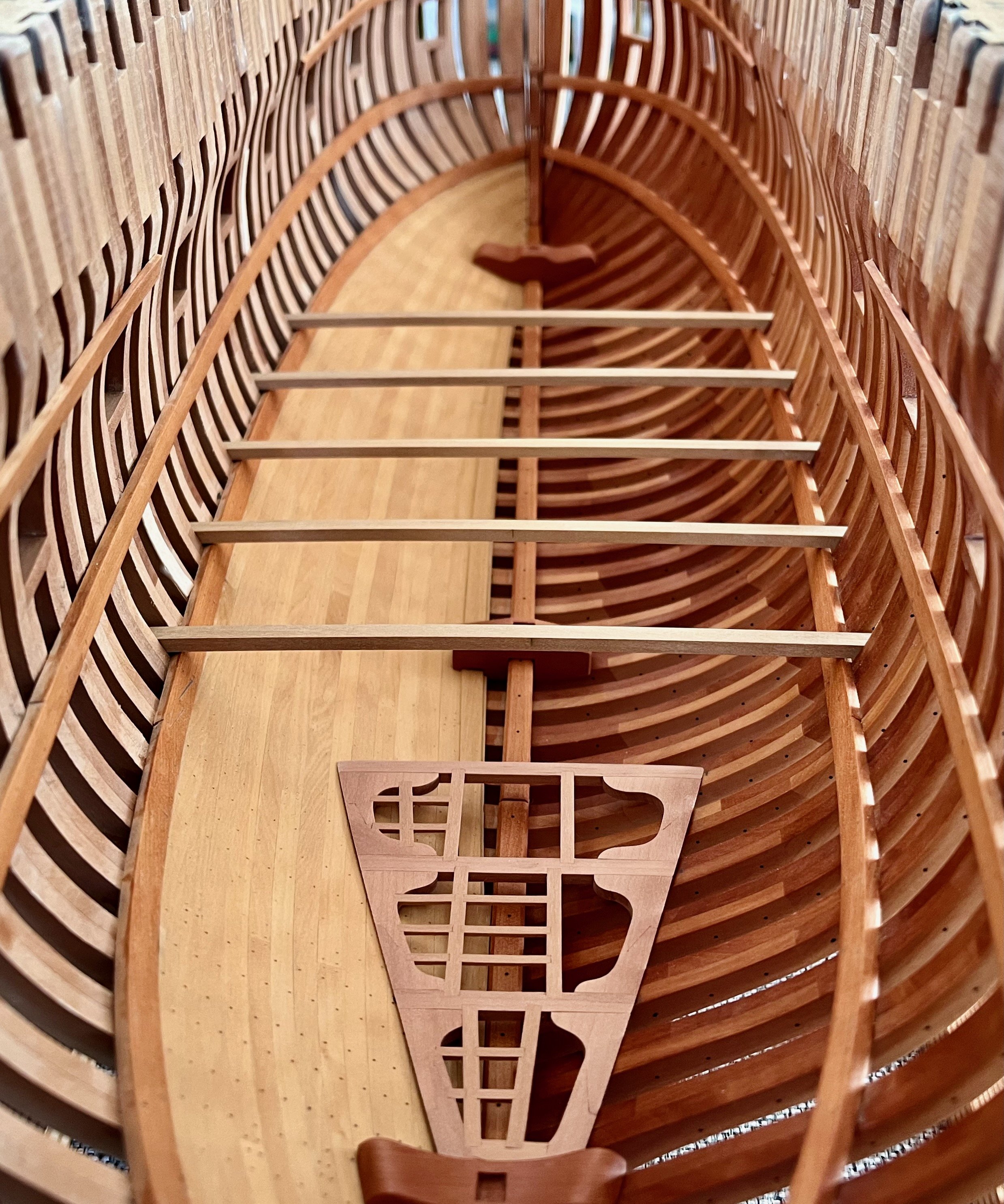
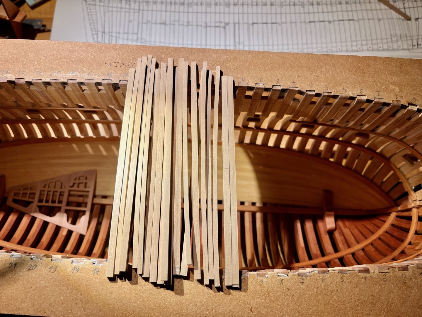
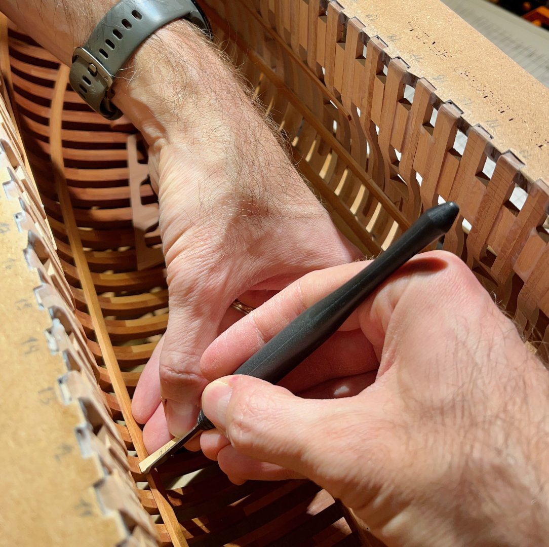
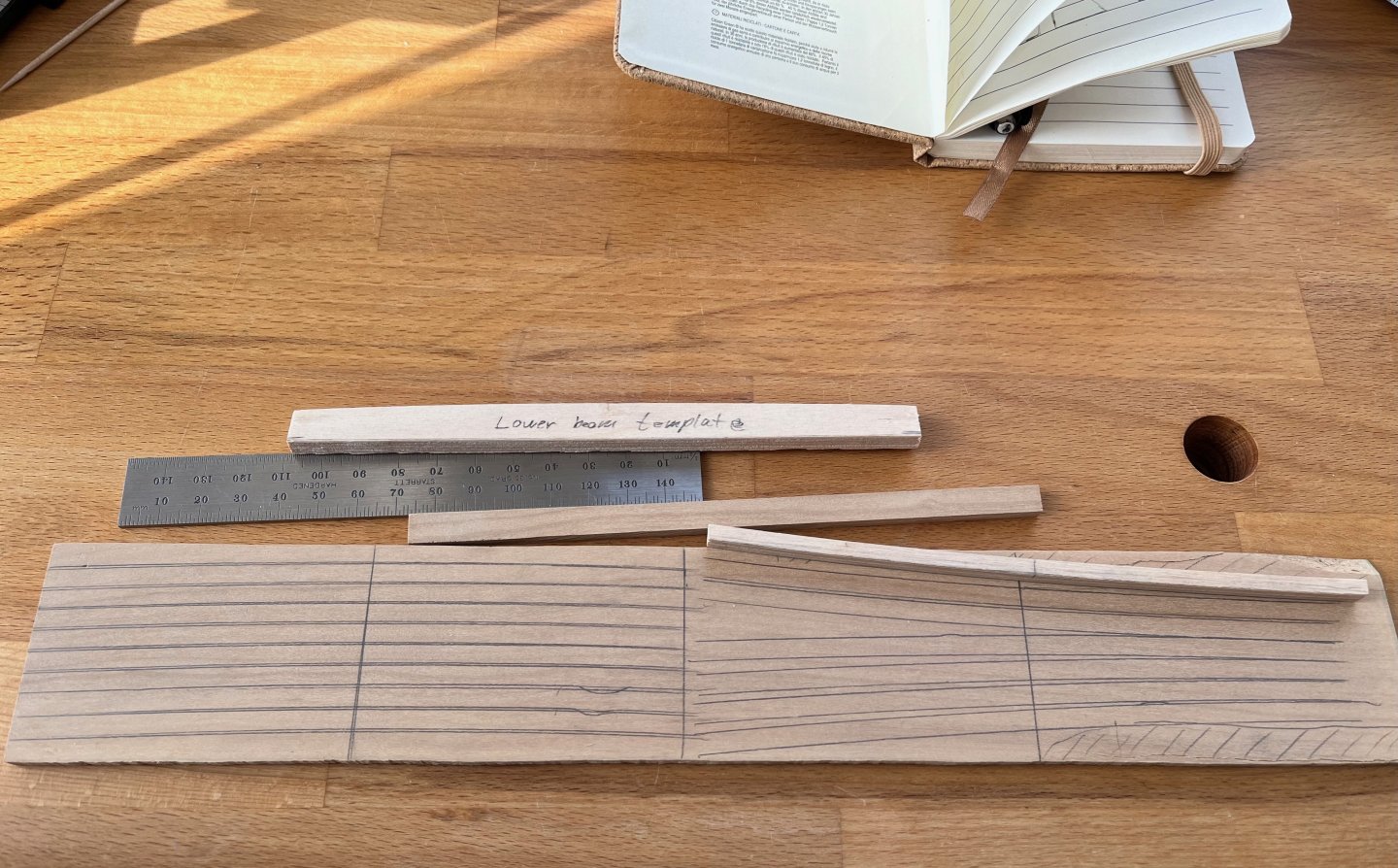
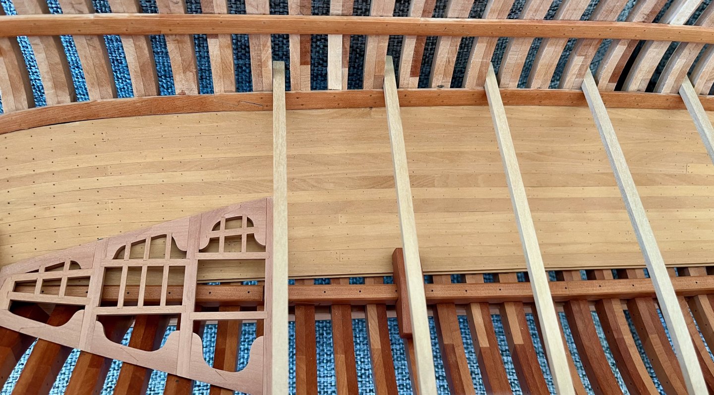
Ok, the modelling block is over, decided to ignore that dip and make a normal straight lower deck like on all the other ships: Remaining beams are cut out of boxwood. Cutting curved blanks really makes a big difference, I extracted 10 planks from the same width of a sheet instead of the previous 6. They are rough from the bandsaw, but milling setup takes care of it, and the result are nice and smooth beams Marking beam locations was a bit nerve-wracking. Pencil was not precise enough when working on such angle, but a marking knife is perfect for that job. Taking a lot of care to not scratch anything around... Finally! I can go back to building instead of overthinking
- 968 replies
-
- 14
-
-
- hahn
- oliver cromwell
- (and 1 more)
-
Thank you both. Druxey, I tried imagining it in 3d (also using Swan and Pandora 3d drawings to help imagining it), and still can't imagine the dip being in place there. I'm likely reading too much into the plans. According to Hahn's book (Ships of American Revolution) the proposed alterations were implemented in reality, and the ship went into British service with all of them in place. Would not doubt his research, definitely not the can of archived worms that I want to open His book does not mention anything on the lower deck details, they were omitted entirely from his model.
- 968 replies
-
- 1
-
-
- hahn
- oliver cromwell
- (and 1 more)
-
Officer quarters are on the "second floor", right above the dotted line. So this modification actually makes their cabins smaller while increasing the headroom below, in the hold. The "step" is around the area with ladders that get down to the hold. Of course I can just remove that extra beam and continue the deck in straight and fair line, like so. But it feels wrong to just "fix" any weird quirk you find on your ship. Strong feeling that I am just misreading the plans and it has a purpose, but I can't find any similarities with similar vessels of that period...
- 968 replies
-
- 1
-
-
- hahn
- oliver cromwell
- (and 1 more)
-
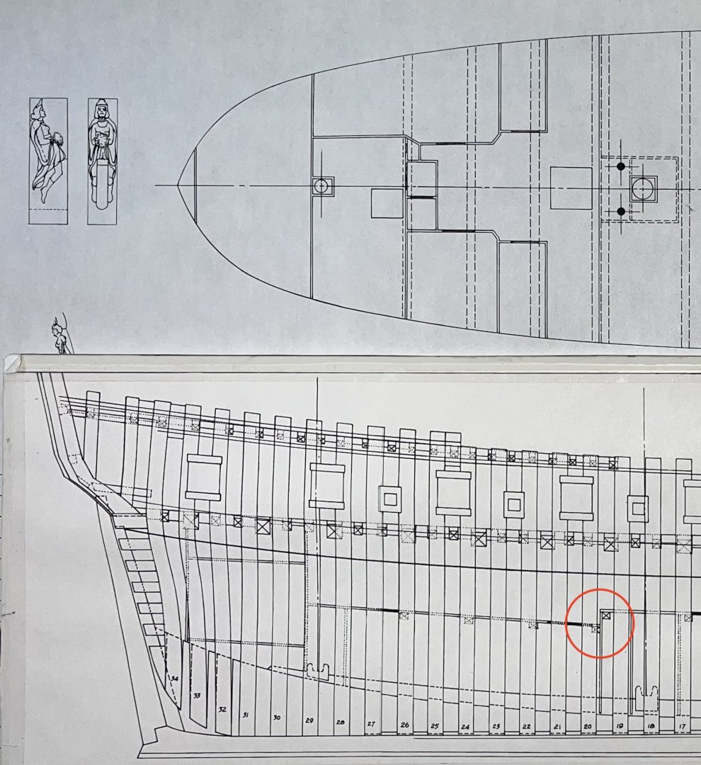
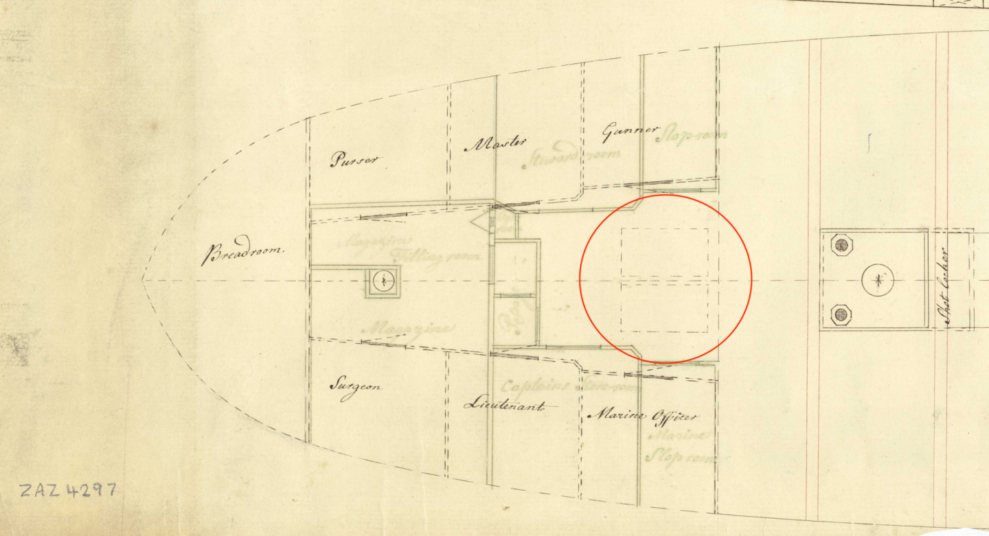
Thanks a lot for the ideas! After looking into Swan's and others layouts the rectangles are now solved - these should be the Fish Room hatches. The only mystery remaining is that step down between two adjacent beams (marked with a question mark in my previous post). It does not look like a sloppiness of a draftsman, he could have easily continued the dotted line to join the "proposed alternation" with the rest of the deck. But he kept those separate on purpose...
- 968 replies
-
- 3
-
-
- hahn
- oliver cromwell
- (and 1 more)
-
Patience paid off! Warm welcome back, enjoy re-learning some forgotten skills The model aged nicely, like the way boxwood deck structure looks like. It got some tan!
- 1,215 replies
-
- 3
-
-
- sloop
- kingfisher
- (and 1 more)
-
Thanks a lot, Oliver! Printed it and can confirm that it works great, even better than expected! I could not find any chips escaping the suction, let allone any fine dust 😊 and no weird noises, the air flows straight and the adapter is very very quiet, you can feel the whole system breathing properly. I increased the dust port height to fit the rubber Proxxon adapter a bit better. Otherwise no modifications were required. Nevermind the rough look when printed with a large nozzle, some construction fairing putty on the inside help with a smooth airflow. Thanks for sharing it with the community!
- 1 reply
-
- 2
-
-
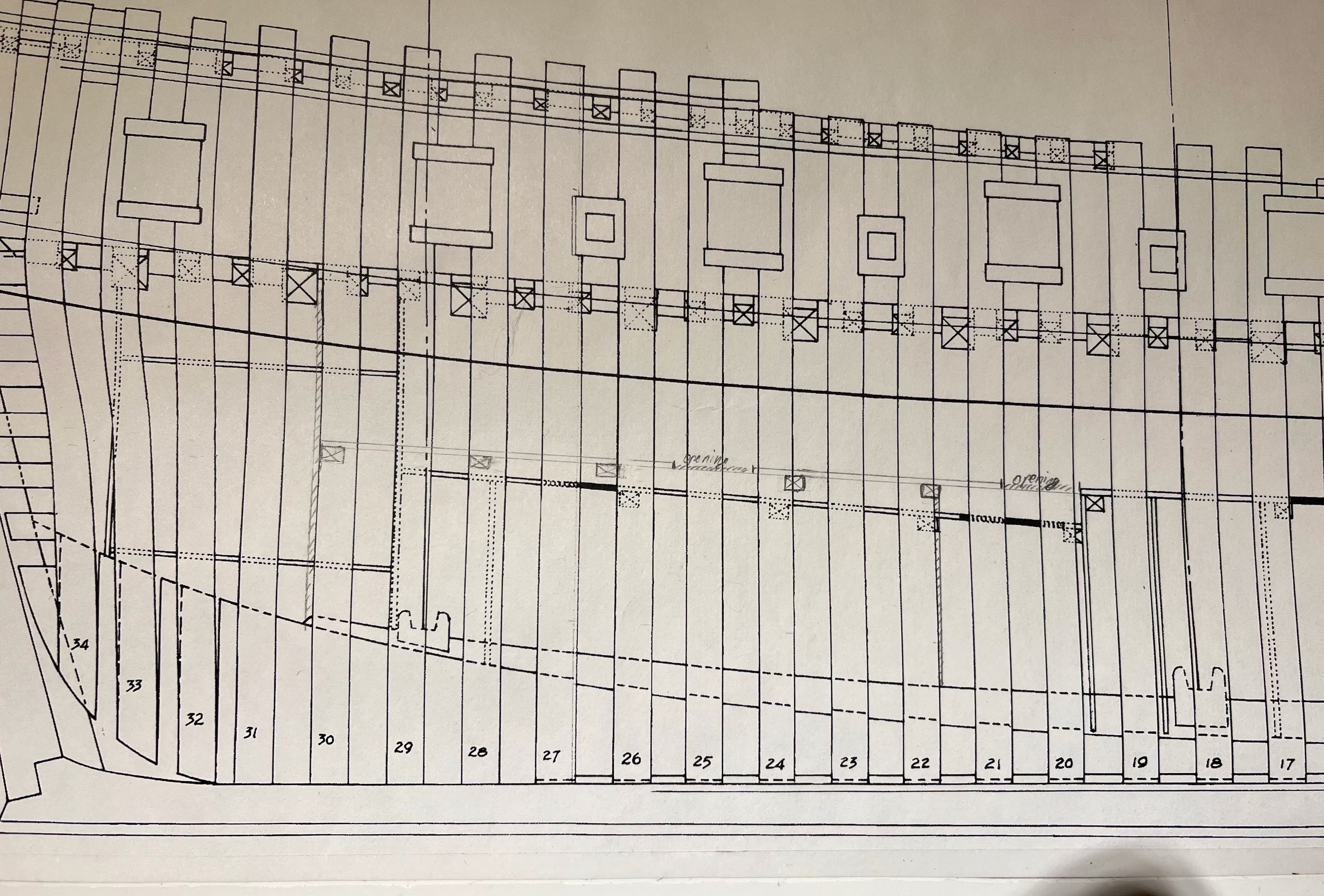
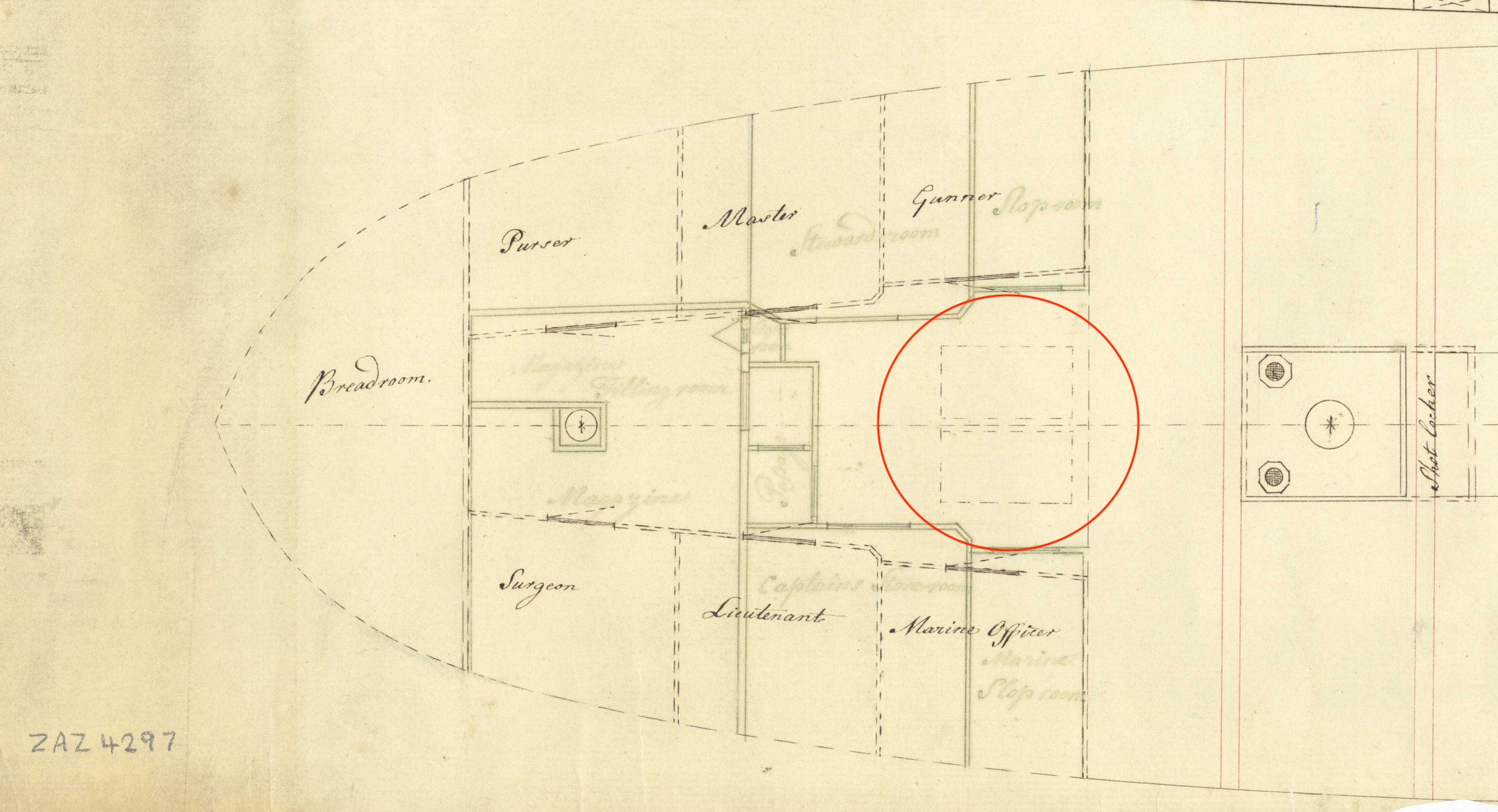
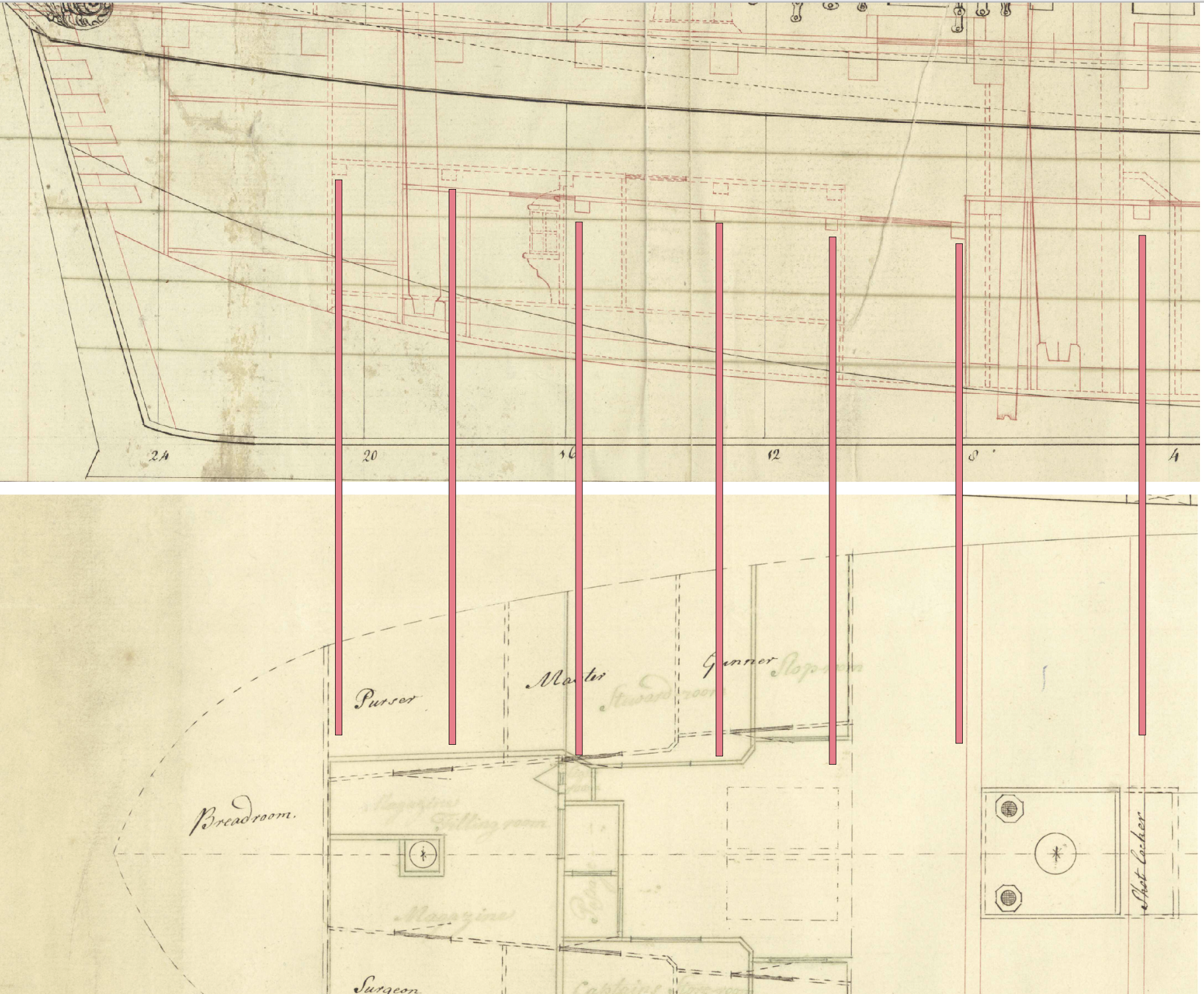
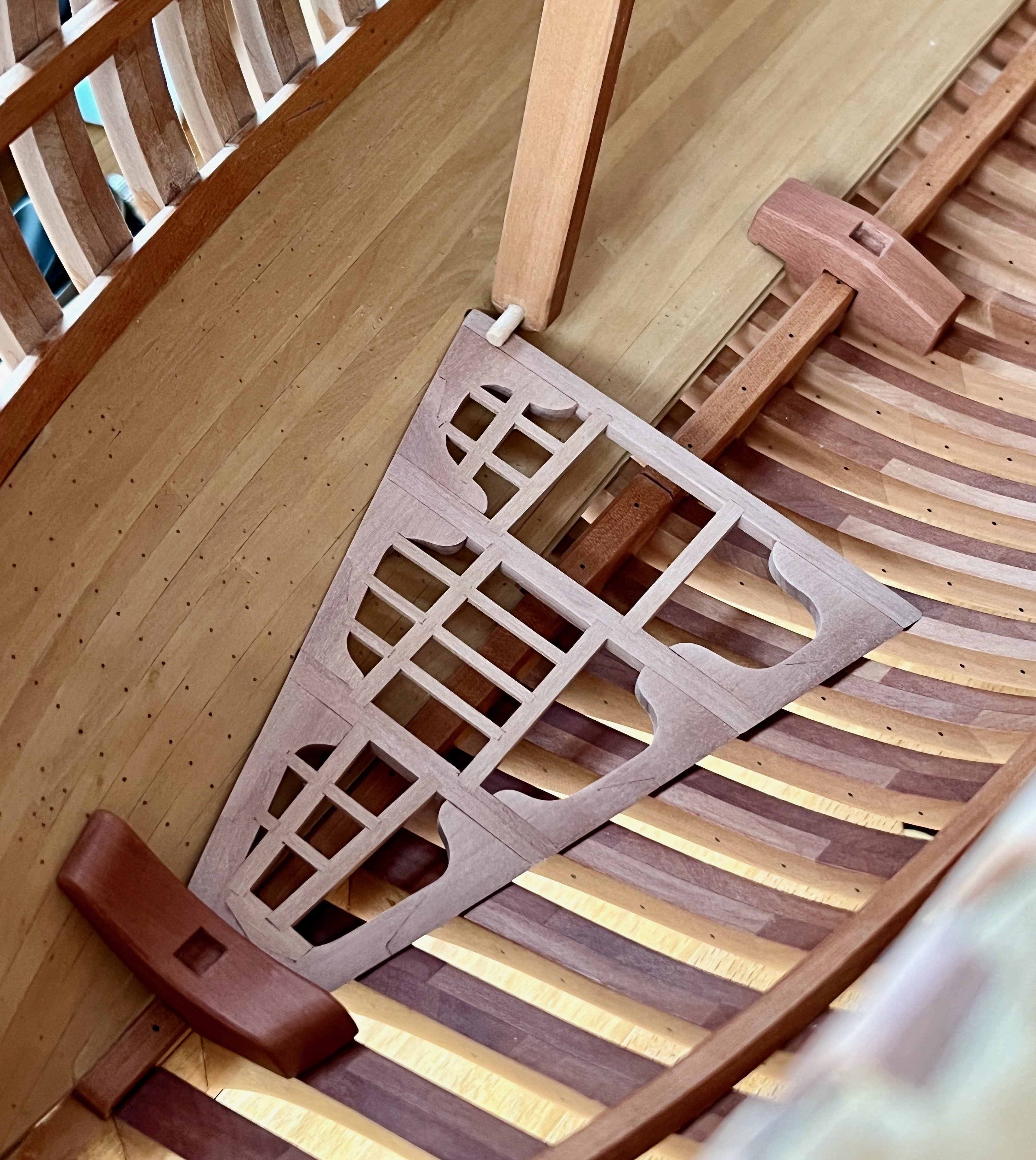
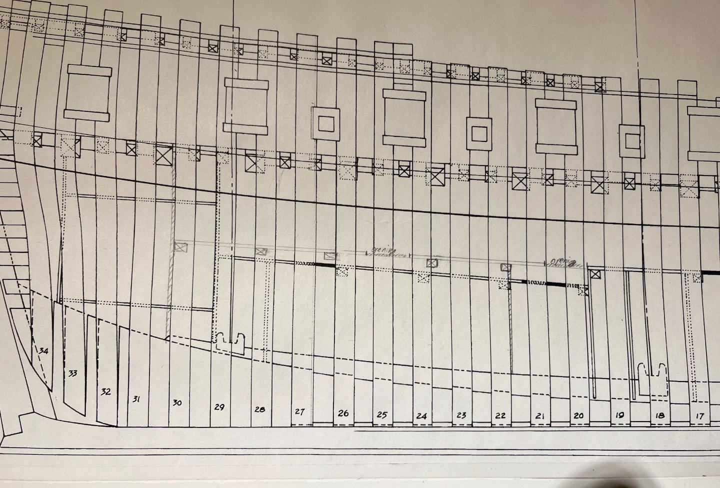
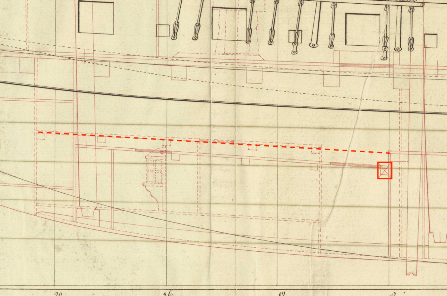
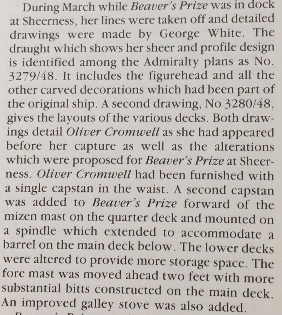
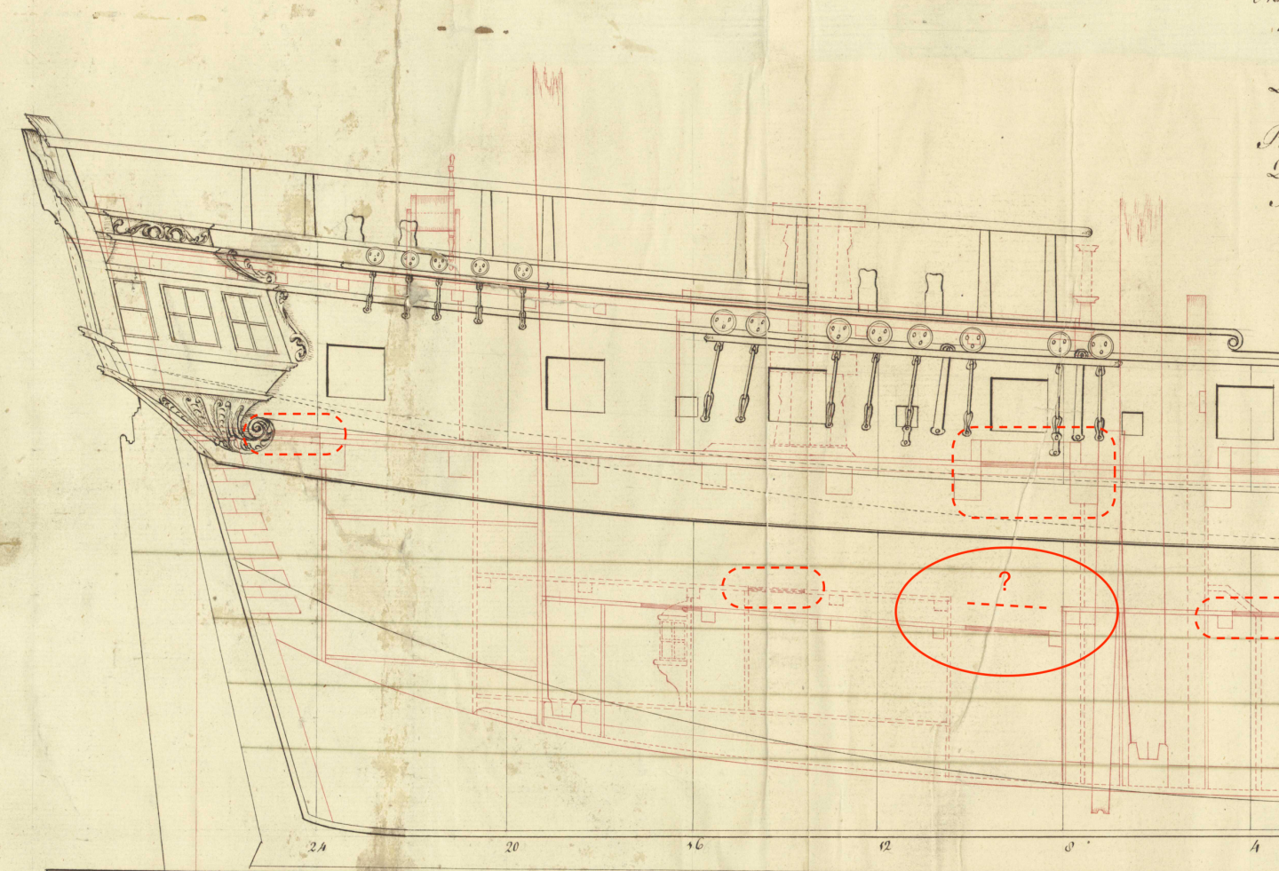
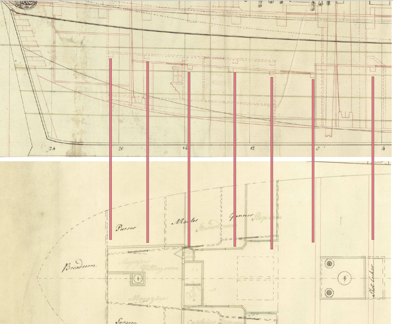
It is time to understand the internals of the ship's lower deck... And it is not easy, even after spending hours with the drawings (both Hahn and NMM archive plans) and my beloved TFFM books. Would really appreciate help from the audience 🤓 Some conventions of the Admiralty drafts are elusive for me, hopefully make sense for colleagues with research experience. Brief background: after the capture the ship was surveyed and slightly modified, and I am building the post-modified, Beaver's Prize version of the ship. The relevant bit: "Lower decks were altered to provide more space" The aft section of the lower deck raises a lot of questions.. Here are Hahn's plans reflecting the original ship, note the strange step in the run of the lower deck. I guess it was done to improve the headroom in the officer cabins? Is that really common? Looks like a hack But once I started looking in the Admiralty drawings from NMM (ZAZ4296 and ZAZ4297) the picture got even more complicated: (the modifications are in dotted lines, that's what I am aiming for). 1) That strange step is still there, but the very next beam is raising the floor back, so it looks like a trap designed to make people trip? Why not just continue the deck in a straight and fair line? 2) Additional beams are added and the deck continues further aft, making the Breadroom significantly smaller. I guess the "additional space" was not for provisions, but for officers, makes sense 3) Btw, what are these highlighted sections on the deck draft? Are these gratings, or scuttles, or ladder ways? Here are two plans aligned: And the last one - what are these two rectangles? Meanwhile I keep cutting some wood while trying to avoid a modelling block because of these puzzles And surely there would be more of those going forward...
- 968 replies
-
- 4
-
-
- hahn
- oliver cromwell
- (and 1 more)
-
I can only imagine how satisfying the fairing would be! There is some real beauty hiding underneath these rough sanded parts 😊
-
Thanks for the feedback and thoughts! Brad, I will aim for some contrast indeed, do not like the bland look of monotone models where all elements are done in the same wood shade. At the same time not likely to paint anything, except some black wales and railings. Giampieroricci's Pegasus is a great example of that - a couple of contrasting wood tones, black trim. Potentially planking above the wales would be slightly darker (light pear?) than the one below (boxwood). The trickiest part is that the visual taste would evolve over years of the build, so a style that I decide on now might get ugly by the time the model is completed..
- 968 replies
-
- 3
-
-
- hahn
- oliver cromwell
- (and 1 more)
-
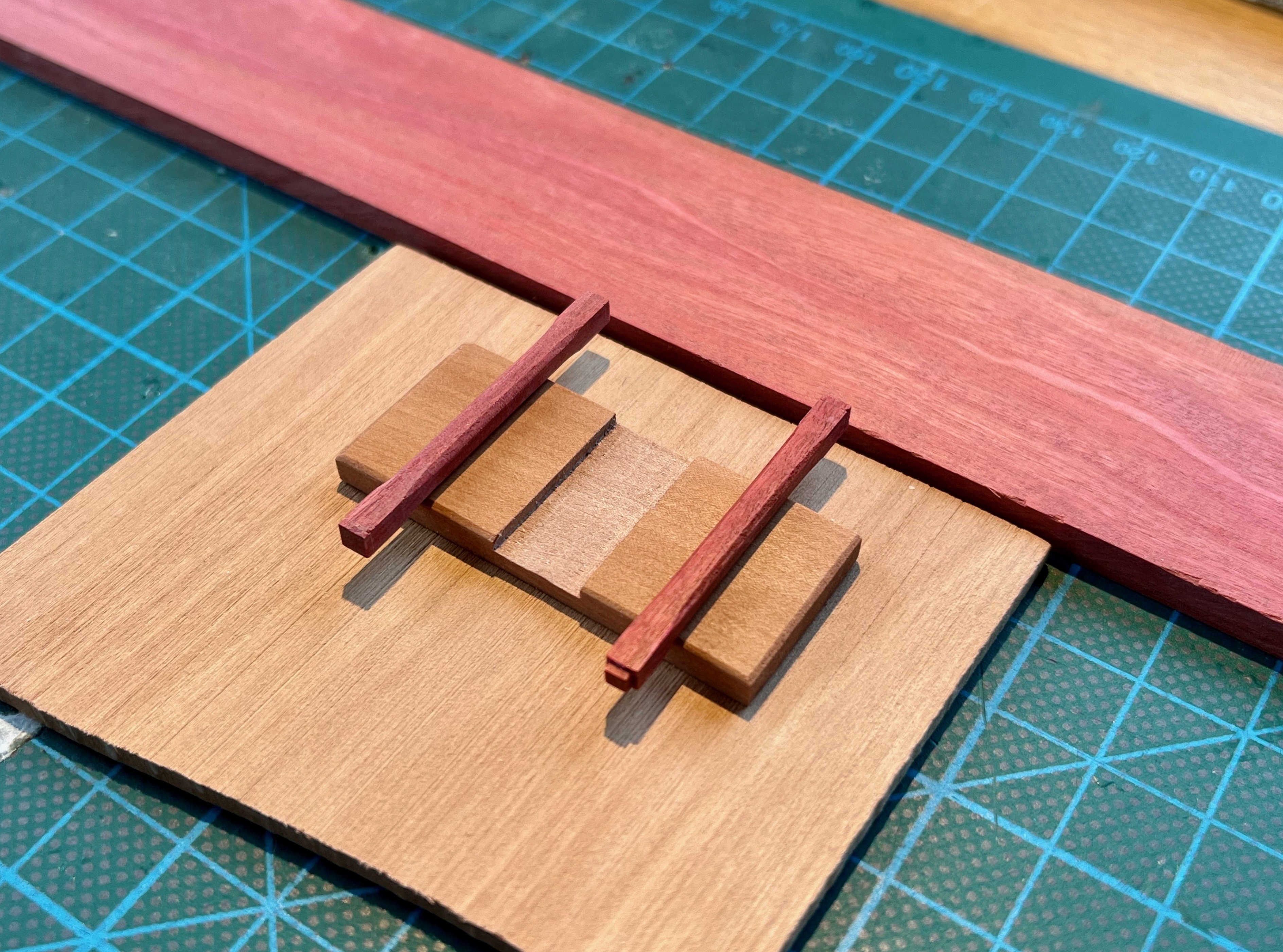
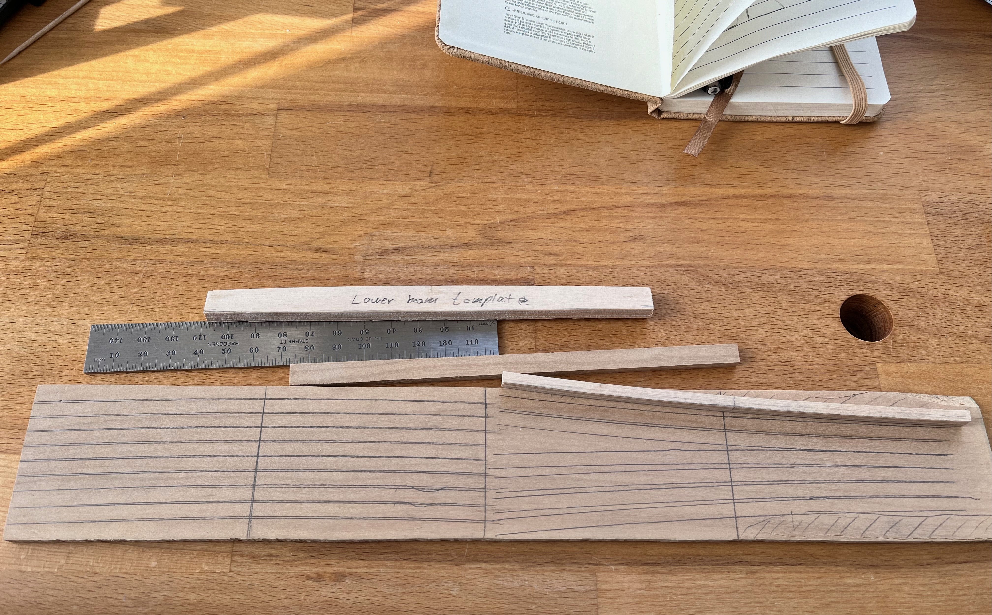
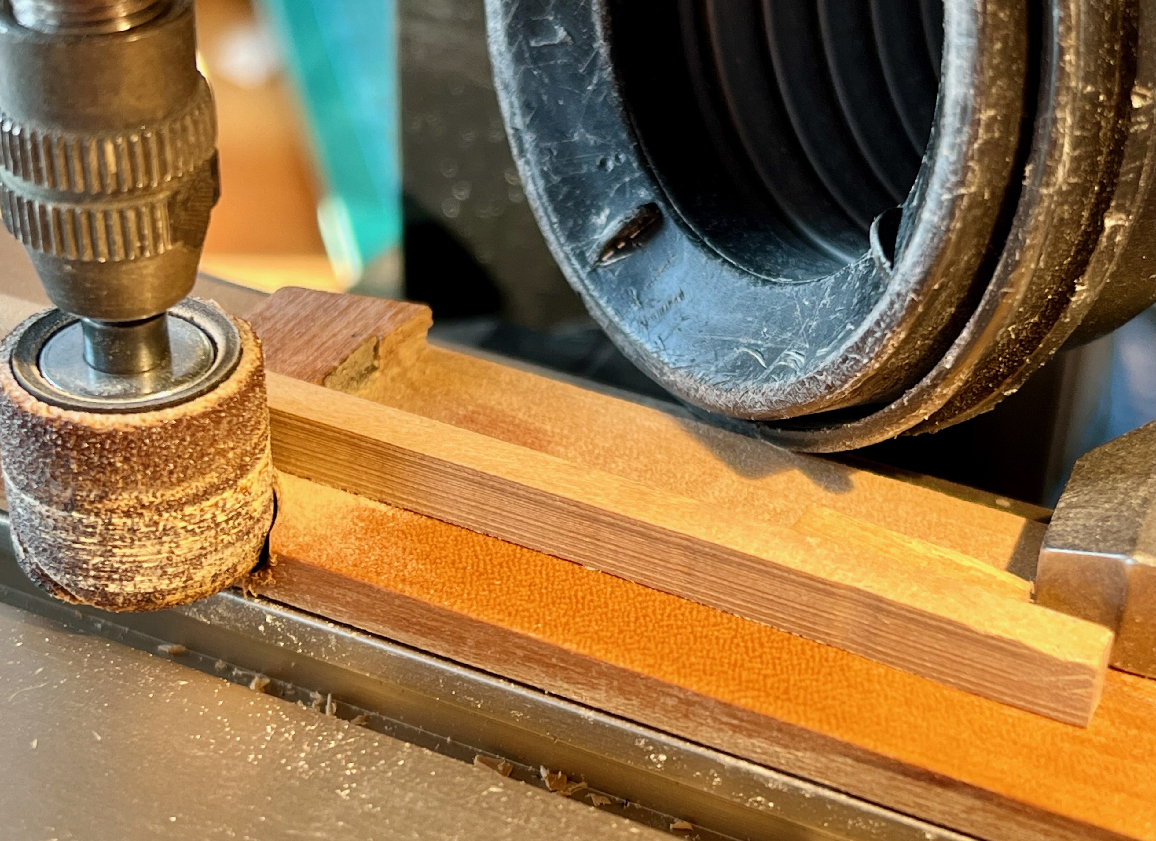
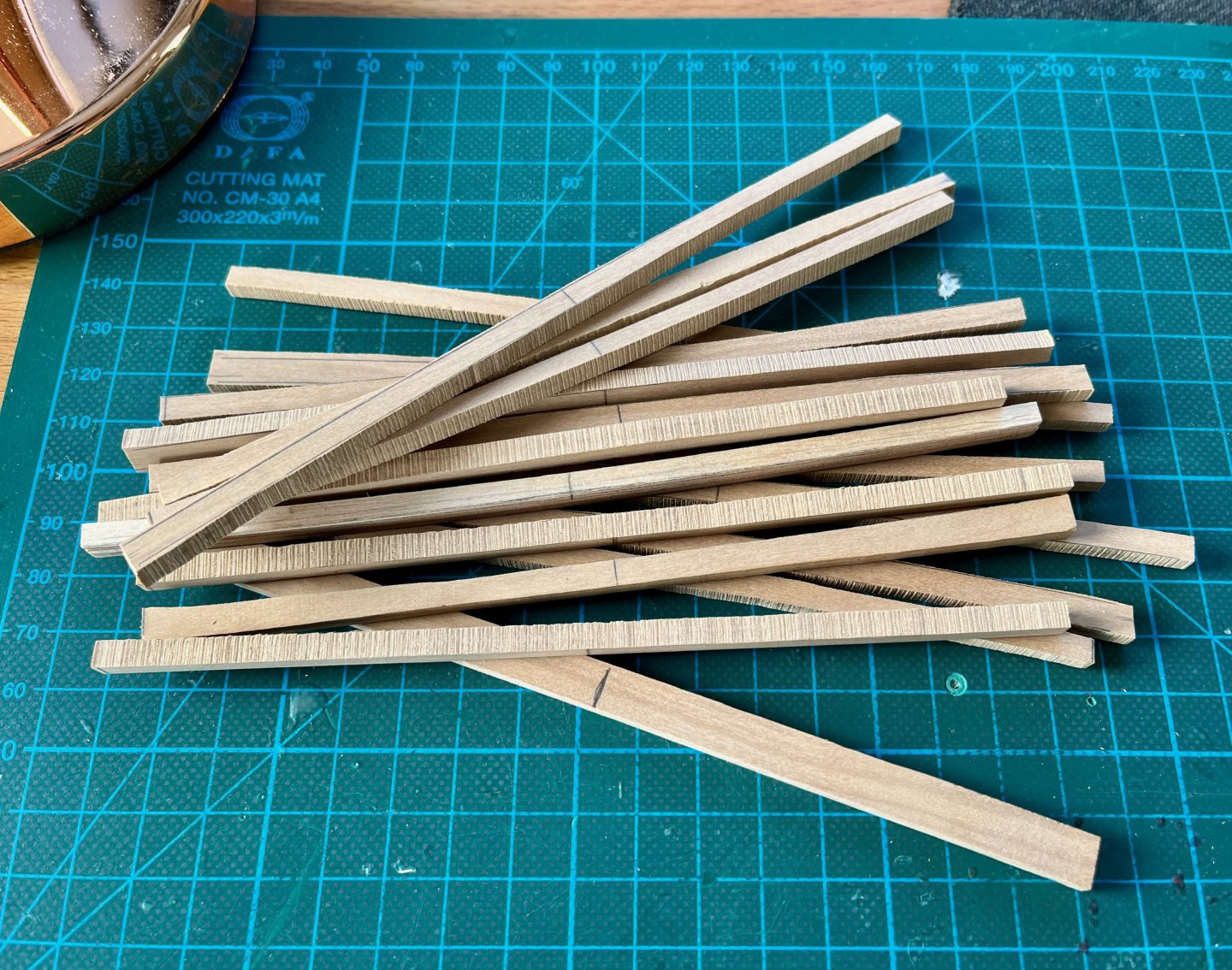
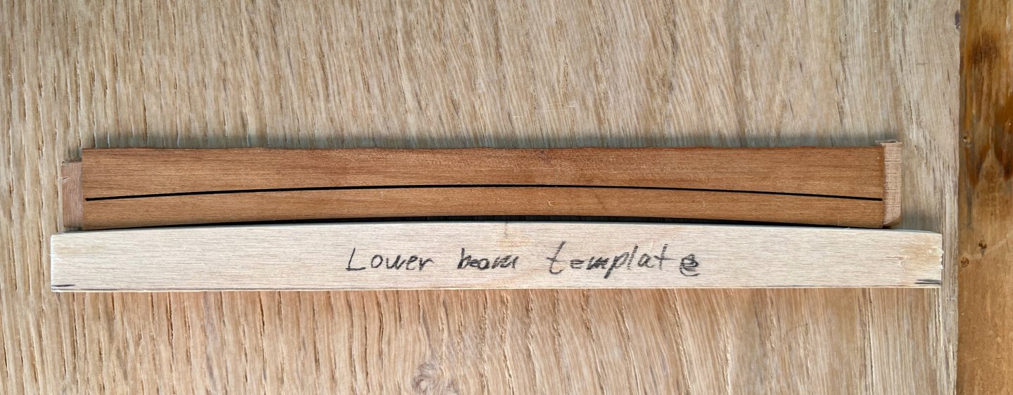
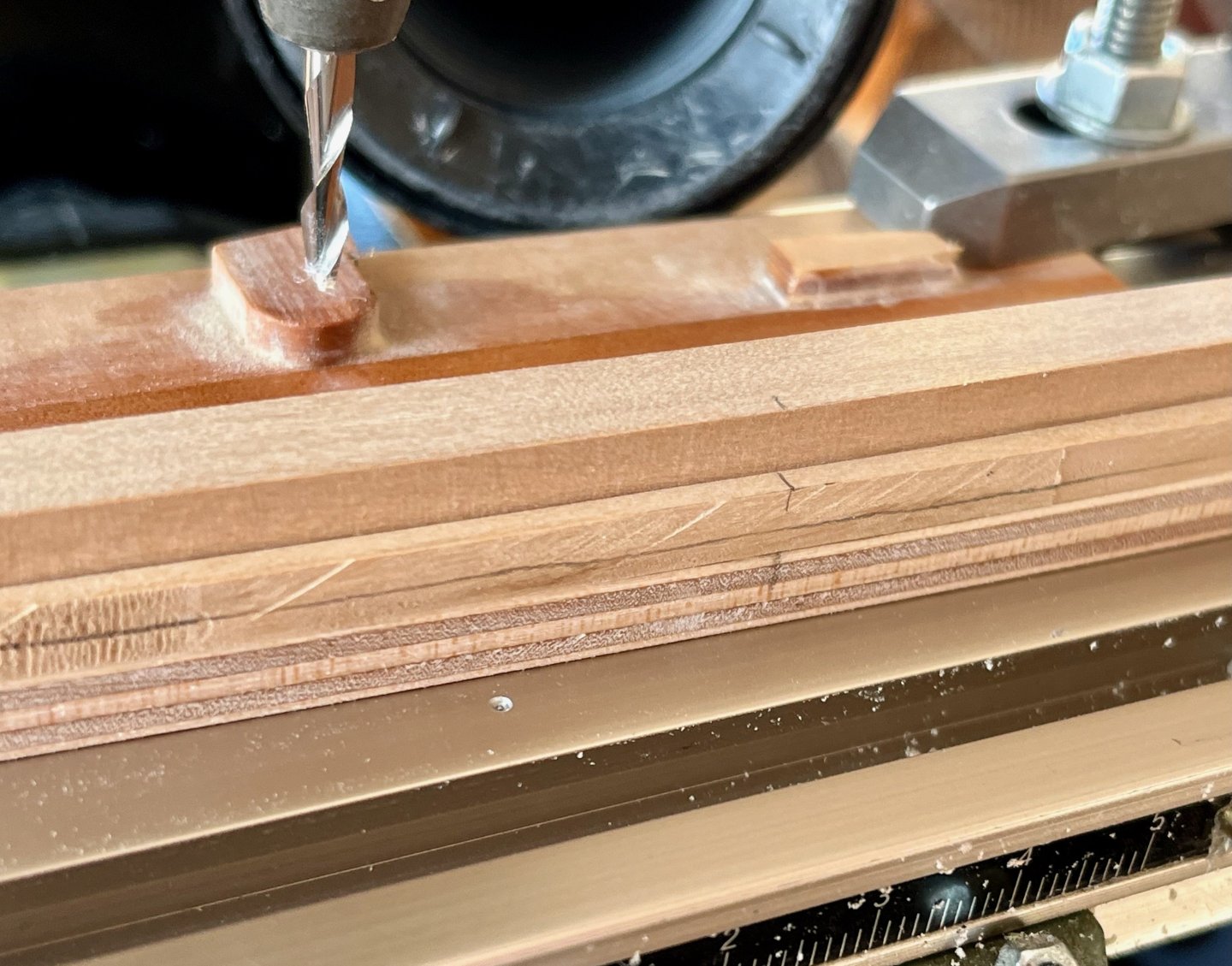
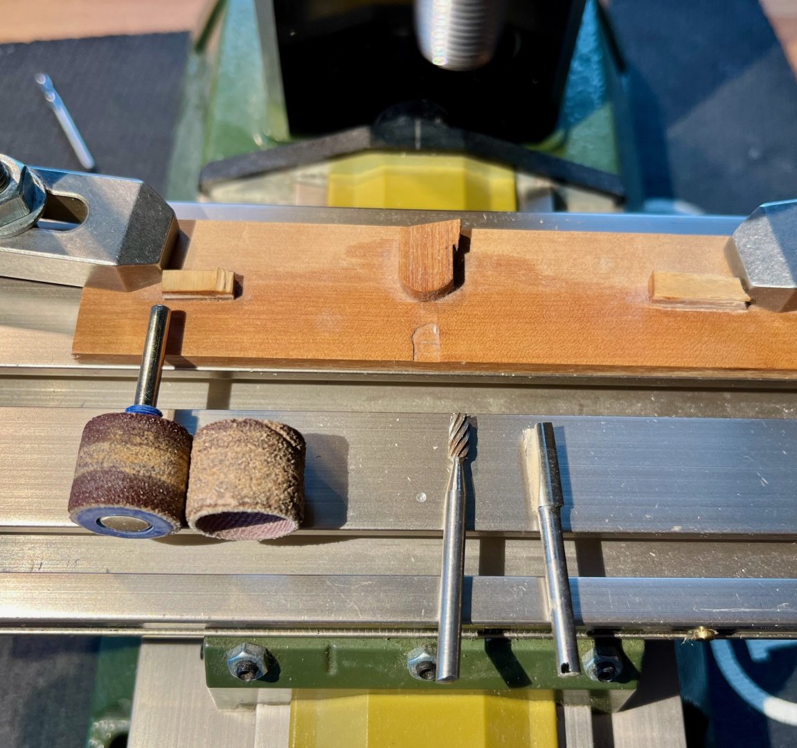
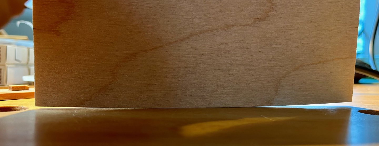
Thank you for the comments, as always! They do help to keep the momentum To proceed with the pillars - I should first dry fit deck beams into their positions. Laser cut beams provided by The Lumberyard in the "timber package" were surprisingly all wrong - too narrow, but way too high. Almost an inverse of the necessary dimensions. Also their arc radius is too small, compare it with the one recommended in TFFM: Making them from scratch is an exciting little brain teaser. There are so many ways! I opted for a template and a mill method. Making the template is a matter of copying the curve from TFFM onto a piece of plywood and gently shaping it. Rocking it side to side against the light helps to highlight the curve. The shaping is done with a router-style jig, I added small tabs to limit the rotation of the part, just in case. The beam is attached to the template using hot glue. Tried double sided carpet tape - it is too flexible, allowing the part to move on the jig. But which cutter to choose from? Plenty of options! After a set of experiments it is clear that you need two different approaches for each side of the beam. Dremel cutters pictured here were quite bad, rubbing the wood rather than cutting it, creating a lot of force on the part. The outside curve is best shaped with my go-to 3mm Proxxon cutter. No effort required to feed into it, it cuts like butter and leaves a super clean surface that needs just a gentle touch-up with a sandpaper. Here is the raw surface after milling (an unfinished blank is below, for comparison): However it does not work on the inner curve - it catches the wood easily and is way too dangerous to operate, since my fingers are quite close to the cutter when feeding from this direction. Using it was like trying to feed a tiger, would not recommend. The best was to use the rotary tool sanding drums - a courser one to remove bulk of the material and a finer one for the last few passes. It does not catch and provides just the right amount of resistance when feeding the part. And much safer - I brushed my finger on it a couple of times and it left no marks, as opposed to the sharp mill cutter that can eat you alive. Of course it leaves sanding marks, but they are not too bad and are easily removed by hand sanding. Also the geometrical consistency is not great, the drum is a bit barrel-shaped. But on that scale (and on the surface under the beam) that deviation is invisible and can be adjusted by scraping it. Now I have first 5 beams, 10 more to go! But now the difficult decision is the type of wood for the lower deck structure. These first 5 beams are made out of boxwood, should I continue the entire deck in box or should I try pear instead (same as on the aft platform)? It should darker over time and be similar to the inner planking. So far I'm thinking to keep the lower deck in lighter colour, so it would be more visible deep in the hold when the upper deck is built. Both decks would get a very minimal planking, possibly no planking at all on the lower deck. The upper deck would be in Pink Pear, I think. But is the boxwood too bright for the lower deck? Of course it is an artistic choice, but would really appreciate some comments and opinions! I'm really bad at trying to find the colour match, but I understand how important that is in a long run 🤓


- 968 replies
-
- 16
-
-

-
- hahn
- oliver cromwell
- (and 1 more)
-
Yes, I need to stack different thicknesses, of course trying to reduce the number of spacers (using one 2mm instead of two 1mm, etc). It's a bit similar to the dado stack on a table saw Since the depth of the groove is around 4.5mm - you do not need that many spacers to tune to the proper thickness
- 968 replies
-
- 2
-

-
-
- hahn
- oliver cromwell
- (and 1 more)
-
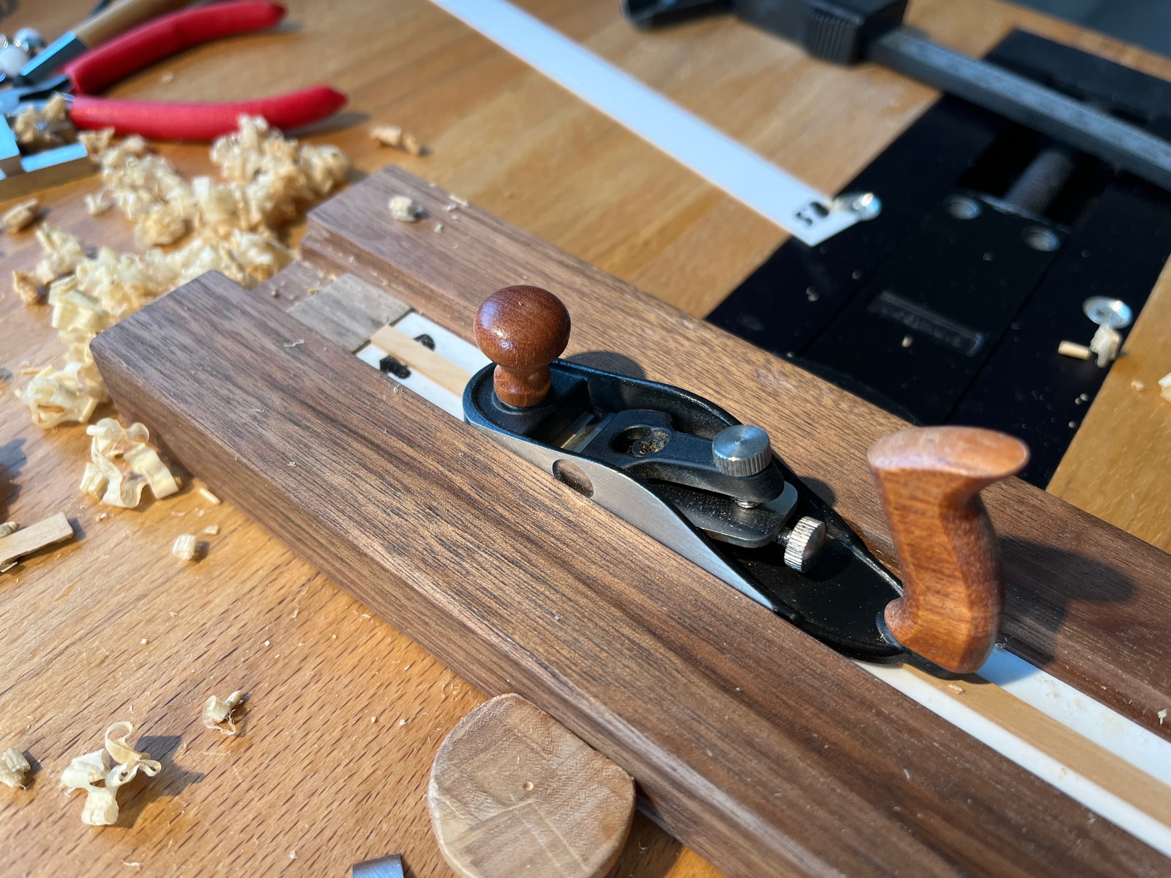
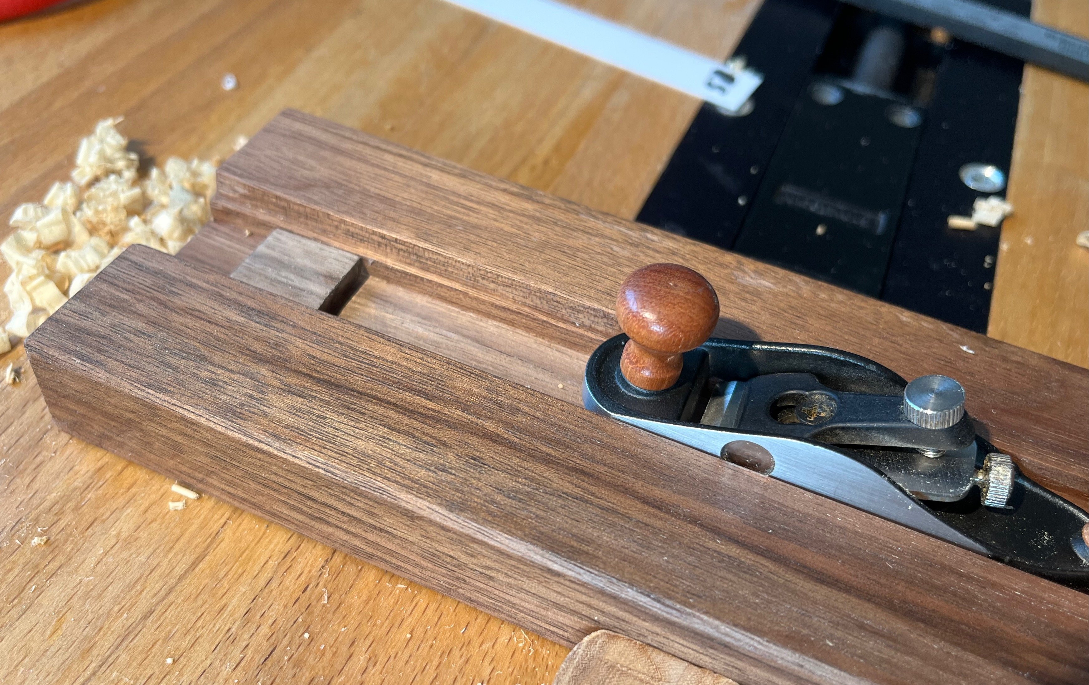
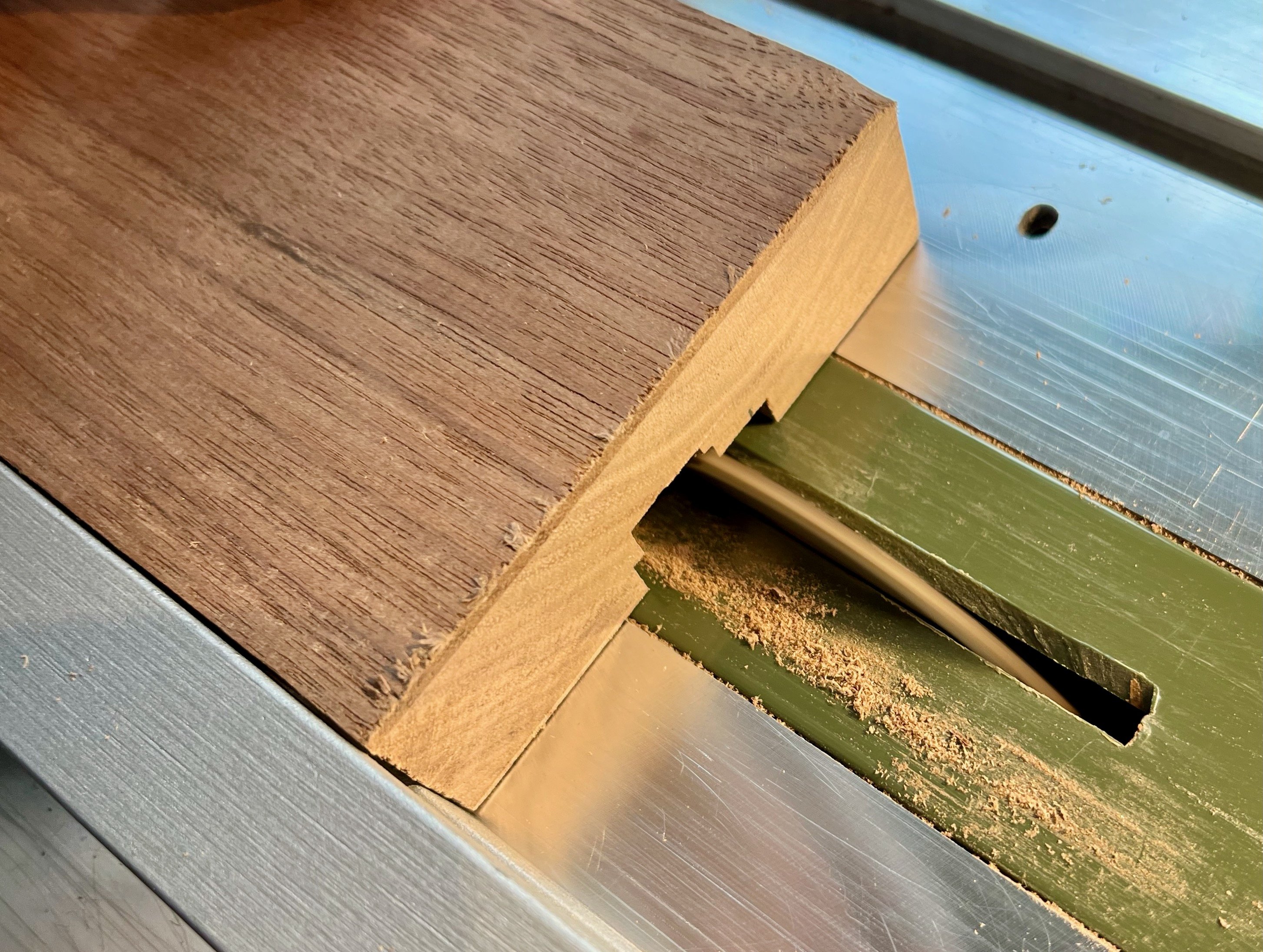
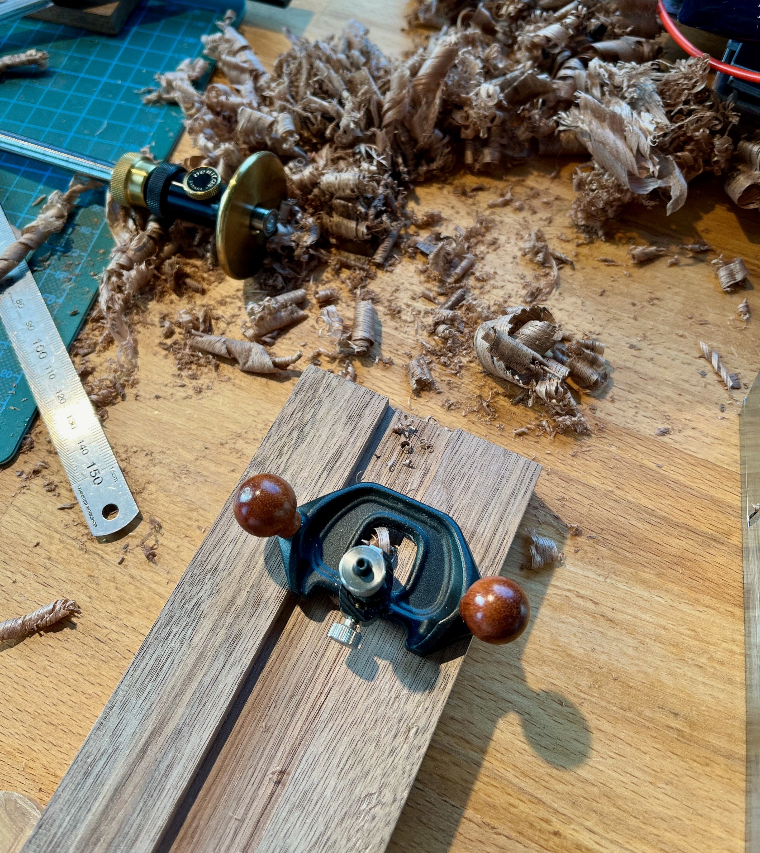
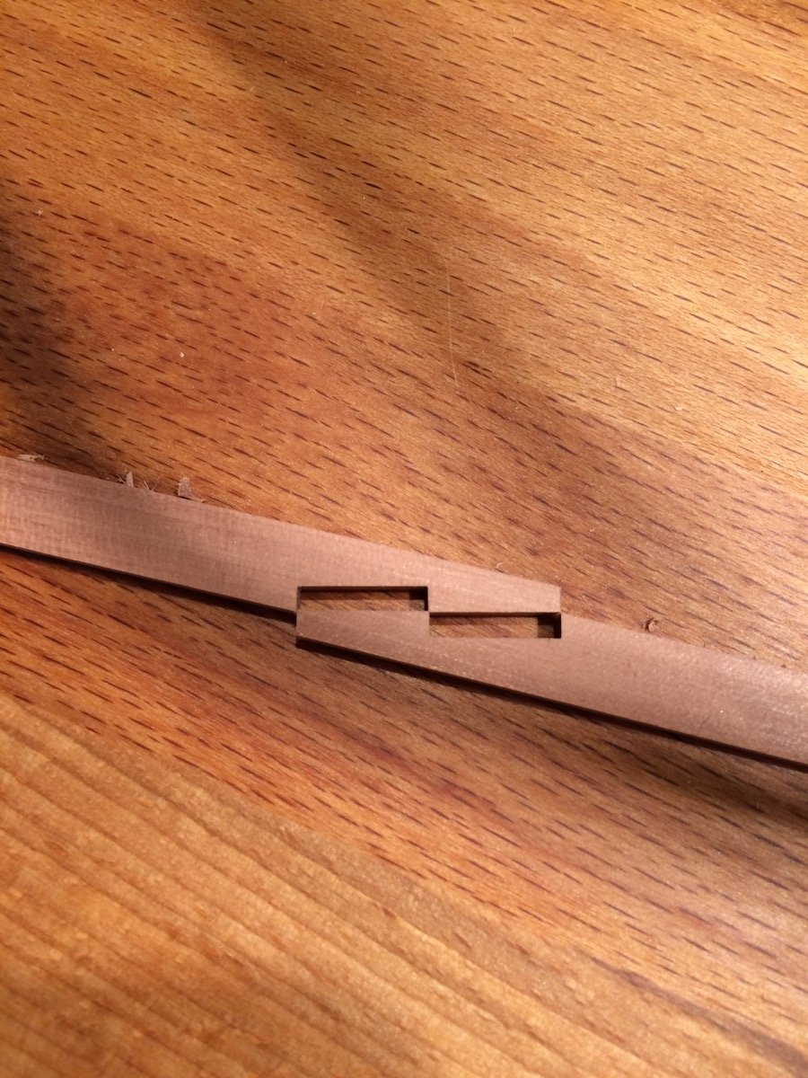
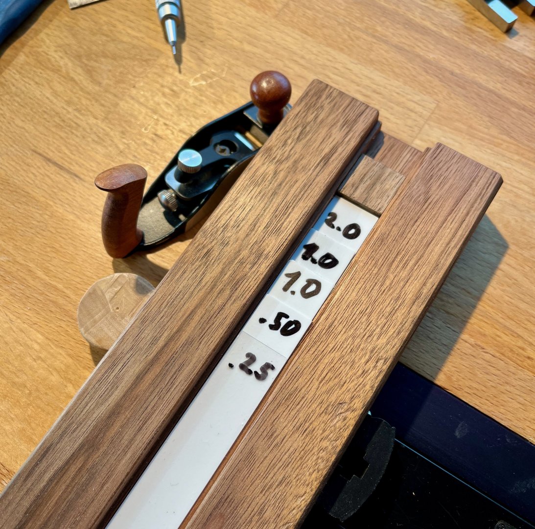
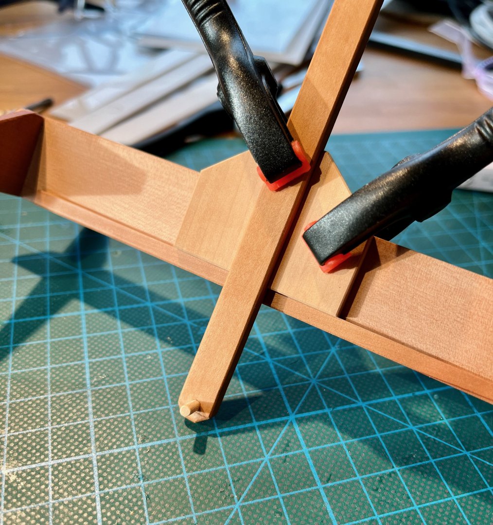
Next up was the problem of wood stock preparation. Majority of the interior construction is made out of relatively small lumber, 2-4mm in 1:48 scale. I could never cut those perfectly on a table saw, they always need a lot of finessing later on, resulting in an uneven strip. The wood sheets I have are 1 or 2 or 3mm thick, so more sanding is needed if you need something in between. The strip preparation was taking too much efforts. A thickness sander would be ideal, but the only one in a small scale is Byrnes, which is rather a collector item nowadays. DYI options are not appealing either, and they are still noisy and dusty. Another alternative is a thickness planing jig. Most of them are too complicated for my task - with knobs and adjustments leading to inaccuracies, so I decided to use spacers. The range of required thicknesses is rather narrow - on of the largest parts (gun deck beam) is just around 4mm thick. Decided to build the jig out of scrap piece of walnut. Did not want to risk using plywood, the grooves might end up on a wrong layer, resulting in an uneven surface. They are tiny, but need to be smooth. Cutting precise grooves on a table saw is not so easy, but slow and steady does the job Router plane helps to clean up the bottom of the groove: Resulting jig, custom made for the miniature Veritas bench plane: Spacers are made out of styrene, very good material for that. Easy to get in a variety of thicknesses, affordable, does not warp with moisture, fairly hard (to avoid compressing too much when planing). I have cut a bunch of spacers with a smallest increment of 0.25mm, should be enough for the range of thicknesses I need. Jig in action: Quite happy with it! Simple jig, but very effective. And perfectly quiet The finish is incredibly smooth out of the box, so I can use the part right away with no further surface cleanup or sanding. If necessary - should not be hard to add a sanding block for the same jig. I could easily get down to 1mm thickness, anything lower - and it is better to hold the "tail" of the strip rather than push it into the stop, otherwise it might get wavy.


- 968 replies
-
- 16
-
-
-
- hahn
- oliver cromwell
- (and 1 more)
-
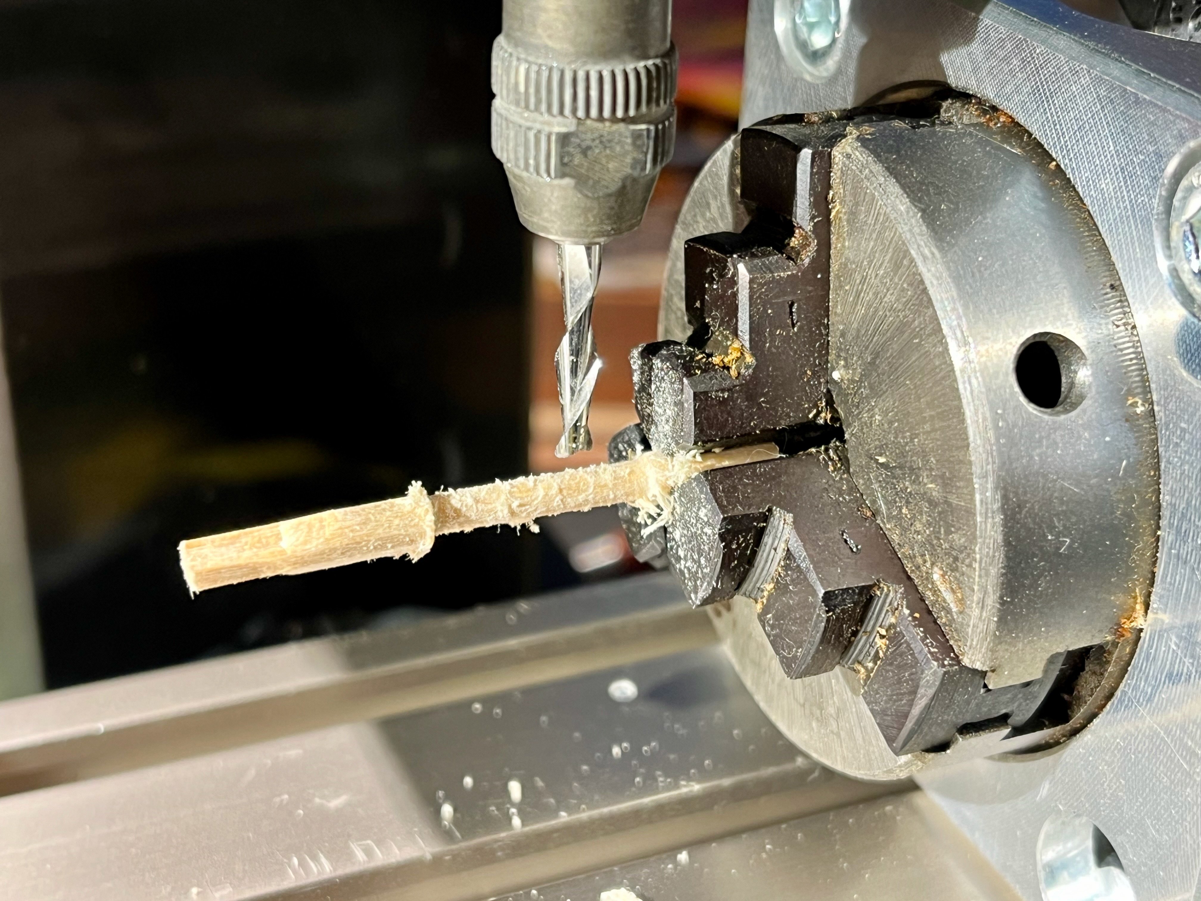
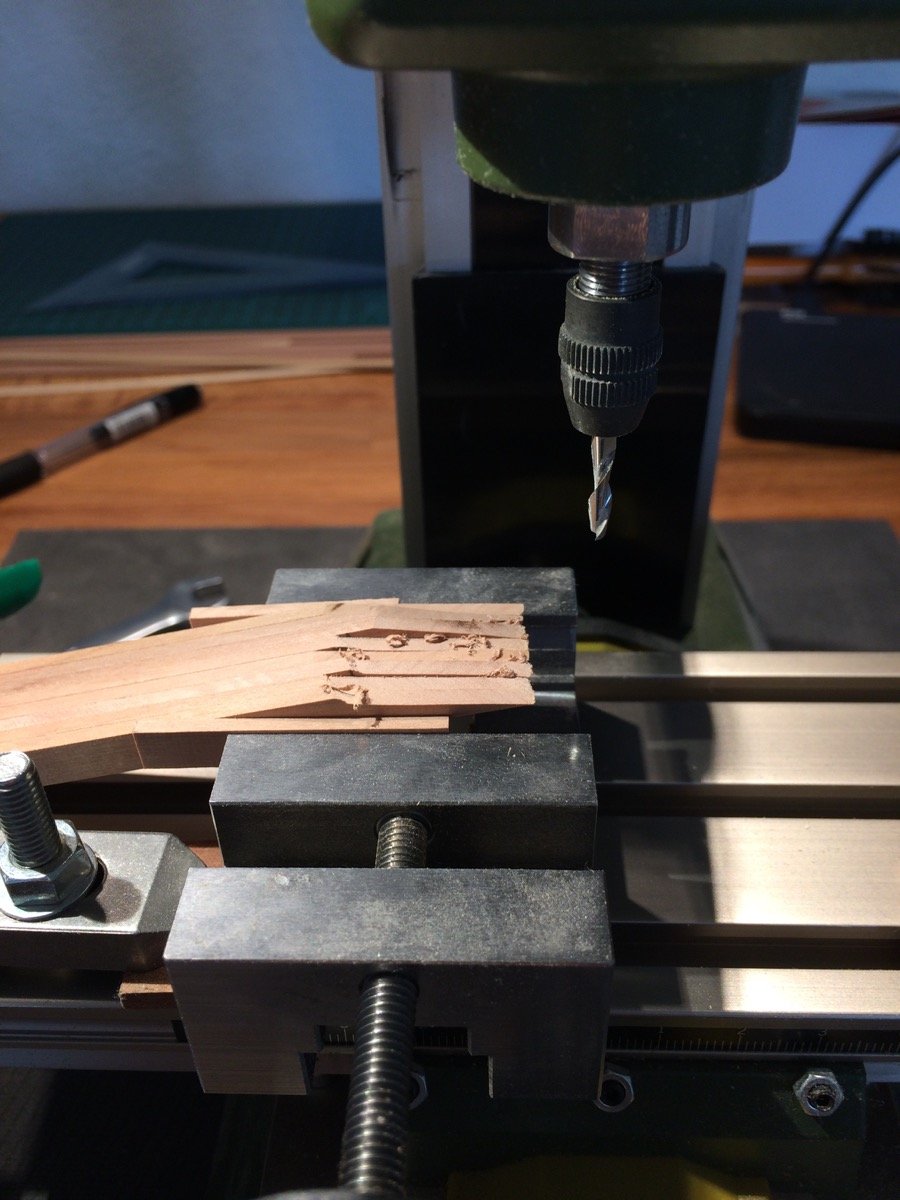
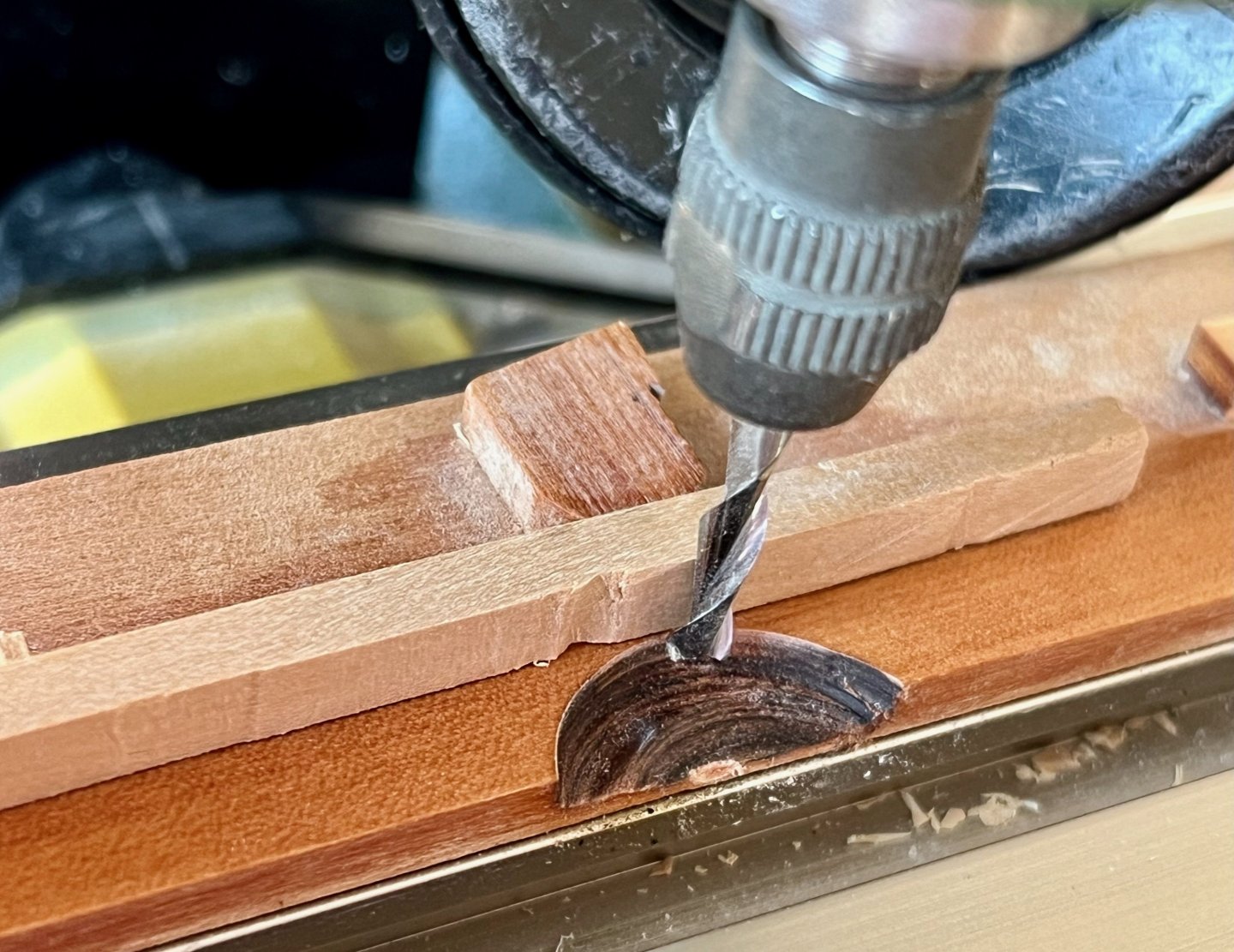
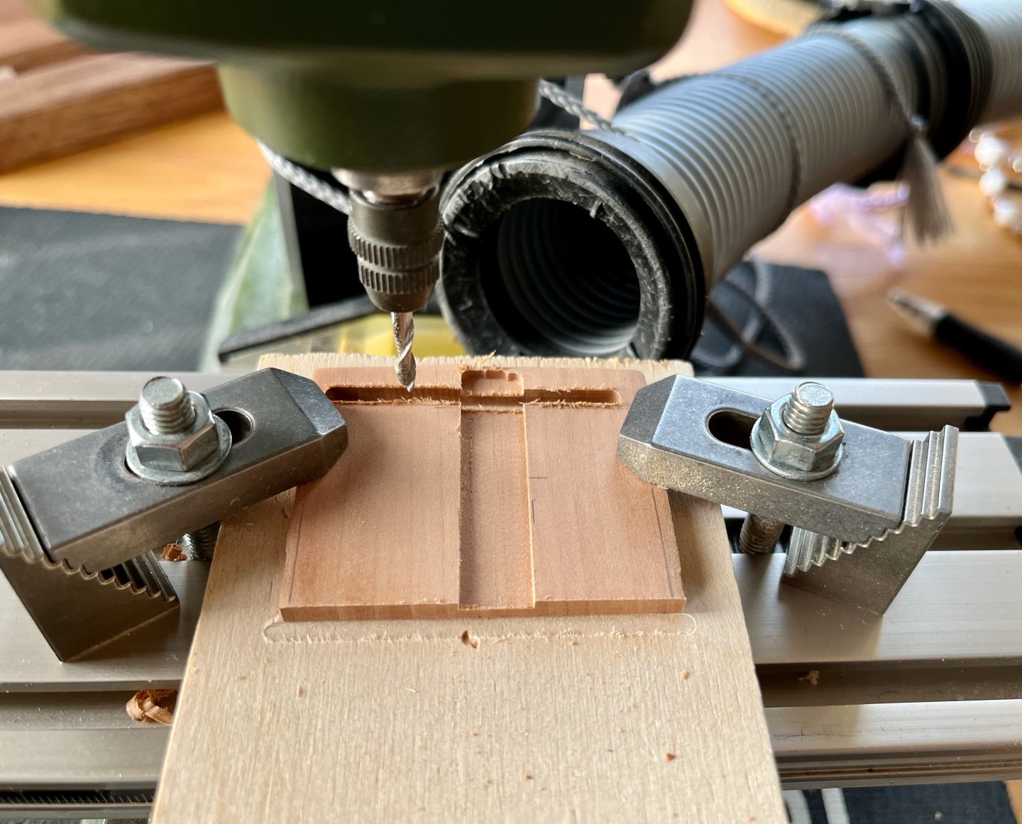
Time for some side projects Fist I was concerned about the side-to-side alignment inside the hull. The height measurement gauge is asymmetrical, and flipping it around may introduce some measurement errors. So I wanted to make a pointy thing that can be moved side-by-side on the top gantry. There was a question in another log - "what is the mill for" - here is a classic example of a simple part that should be square with a precise and square-profiled recess. Mill is much more consistent and requires less skill than a "well tuned table saw", for example. For the "pointy bit" I needed something very soft to avoid scratching the part. Basswood from the Model Shipways kit was ideal - I use it a lot as a soft lining for clamps and jigs. I wanted to practice milling it in a rotary table instead of using lathe or a rotary tool. Not the best idea, the finish was not smooth at all (though such a soft wood is not making the task easier) The resulting gadget. When in action - only one clamp is holding the arm in the correct position, while the assembly slides side to side. Should work even with curved beams, by probing the ends of the beam. In action:

- 968 replies
-
- 15
-
-
- hahn
- oliver cromwell
- (and 1 more)
-
The "previous experience" looks quite nice to the naked eye, though it's hard to see misalignments from the side. Welcome to the club, I also restarted my model after the first dozen frames Later on you would not regret it, the rebuild is done relatively early in the journey! Any fun plans for your hull #1? I tried to repurpose a section of mine as a jewellery hanger (when flipped upside down)...
-
Pardon my ignorance, but what is the actual purpose of the drill press in our hobby? A lot of people are using it, but how? Feels like I’m missing out on something obvious 🥲 The majority of holes on the ship model are planking treenails, and those are easier to drill once the planks are glued in place to ensure a nice line-up of the holes. The only other thing to imagine is a scratch production of rigging blocks and deadeyes, but how many people do that? Not trolling, really would like to understand!
- 53 replies
-
- 4
-
-
- Drill Press
- Milling
- (and 1 more)
-
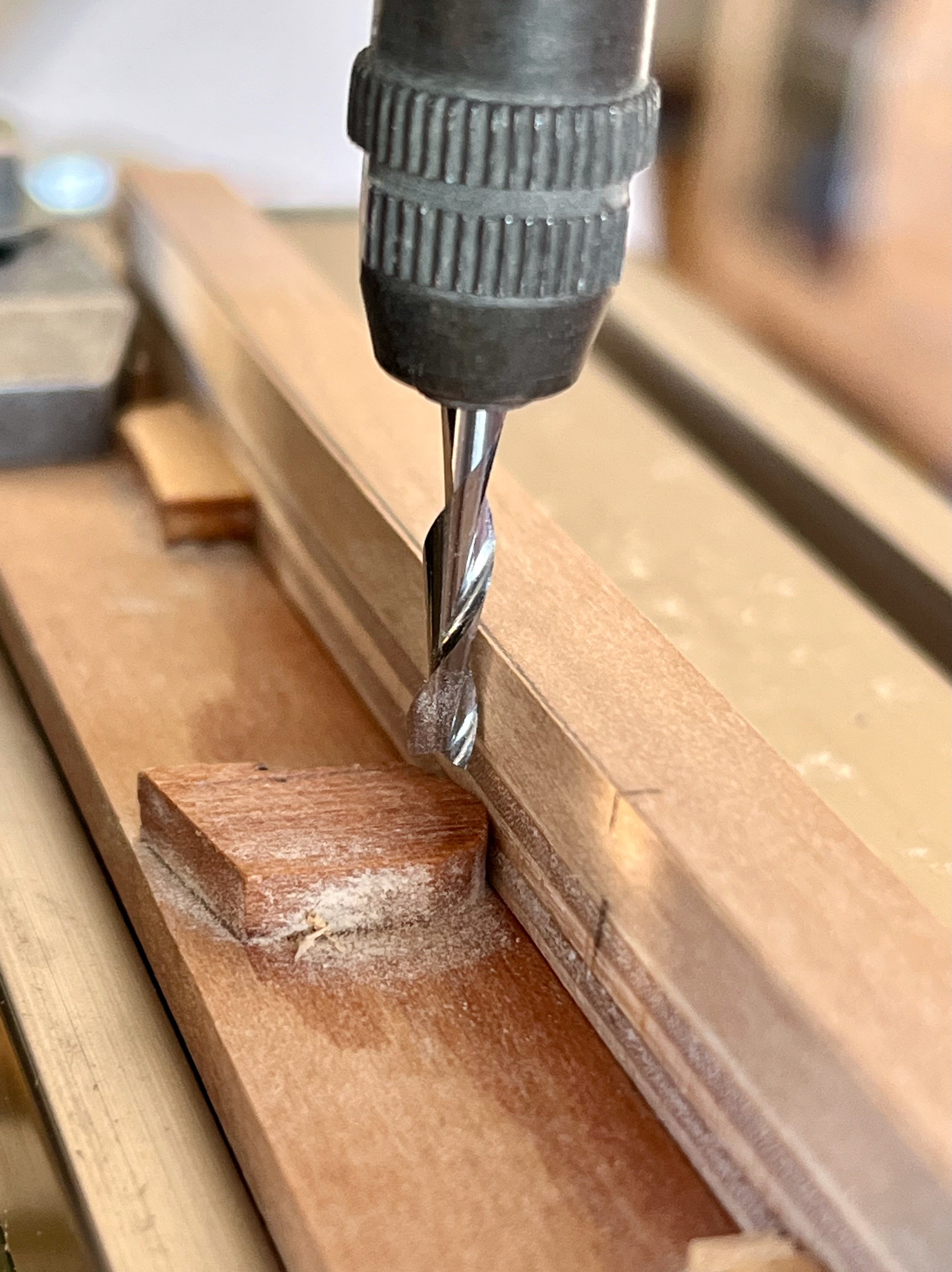
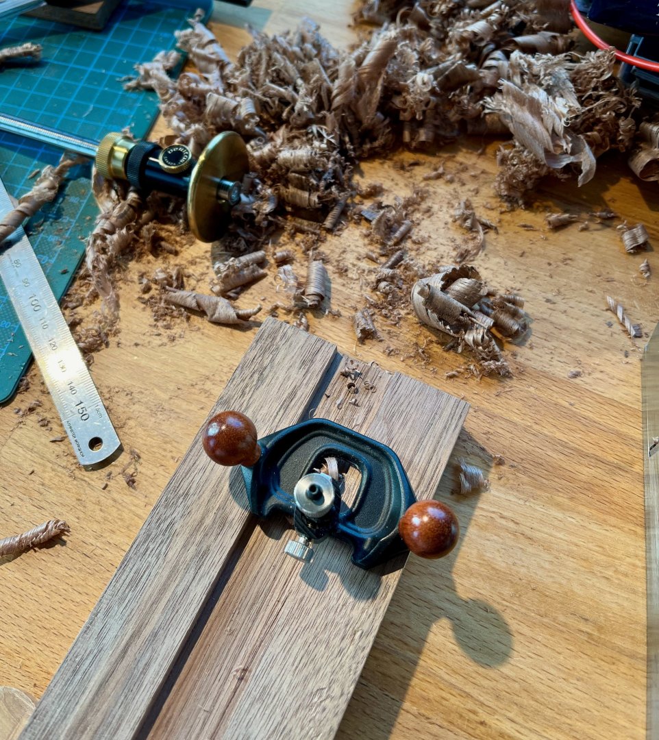
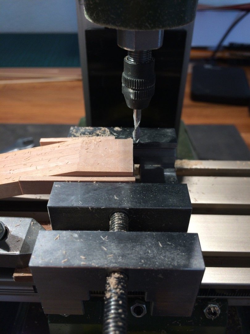
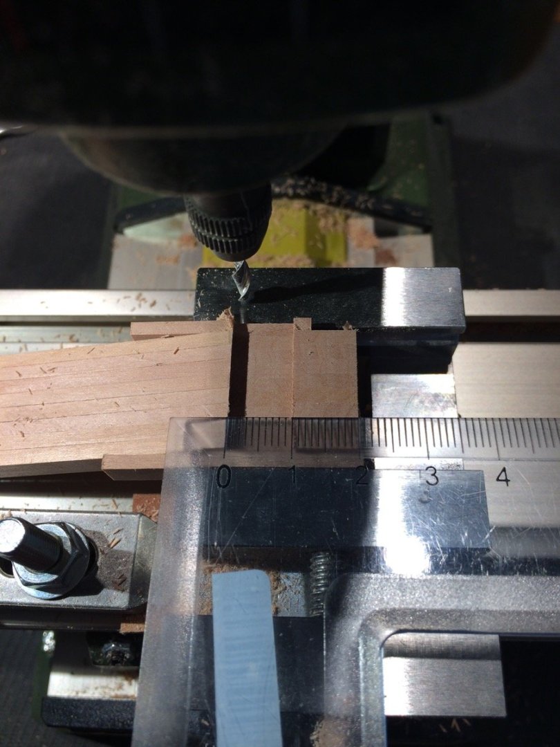
The vertical axis on the MF70 mill is notoriously not so easy to rotate (there is a common upgrade - installing a small axial bearing, helps a lot!). So if you actually want to drill a hundred holes with it for some reason - it would not be a pleasant process. However it is great as a mill, one of the most commonly used tools in my build at least. Not only for "milling" in a complicated way, but for a lot of precision work. Cutting joints in thick planks to make sure are square in all directions, making a surface flat or square or parallel, etc. Even "making sure this part it is exactly 12.8mm long" - doing that on a mill with the compound table is sometimes easier than sneaking in on a fit with a table saw or a disk sander, more controlled and a nice surface finish. If the part is not curved and has some straight daces - chances are I would shape it on a mill from a rough cut blank. Buy the PM40 vise though, without it you are very limited in clamping options. Example of the typical milling usecase, which is even hard to call "milling". Just a "cutting wood using the X-Y table instead of manual measurements, and no need to worry about keeping a straight edge".


- 53 replies
-
- 5
-
-
- Drill Press
- Milling
- (and 1 more)