HOLIDAY DONATION DRIVE - SUPPORT MSW - DO YOUR PART TO KEEP THIS GREAT FORUM GOING!
×


EdT
-
Posts
2,213 -
Joined
-
Last visited
Content Type
Profiles
Forums
Gallery
Events
Everything posted by EdT
-
Hi Guy, The block on p 79 was the first version - made with small nails. They were a tight fit in the holes and not glued. The new fixture has the pins glued in with thin CA after I checked the heights of the pin points. This is only to keep them from falling out. There is a brass plate and a hardwood block underneath to take the impact. I will take a photo for the next post. Ed
- 3,618 replies
-
- 1
-

-
- young america
- clipper
- (and 1 more)
-
Richard, what diameter were your lancets? I found that with very small ( .014") syringe, the heads were too large. I am using the actual points on nickel coated steel dress pins in a boxwood block with the pinpoints only a few thousandths above the surface. I did basically as you described when I made the test with syringe tubes. I did not grind the pinpoints, but machine ground the other cut off ends to get the height uniformity. These were backed with a brass plate. Only after testing did I CA glue the pins. Ed
- 3,618 replies
-
- 2
-
-
- young america
- clipper
- (and 1 more)
-
Richard, I personally would not use soft solder for something like this. Silver solder is much stronger. I would be concerned first about the joint breaking when you saw off the parts, then later breaking on when the rudder is installed and it is too late for a repair. There is virtually no risk of this with a silver soldered joint - if it is a good joint. I may use soft solder to fasten the pins into the pintles but there is very little stress on those joints and if I silver solder them there is a risk of opening the first joints. Ed
- 3,618 replies
-
- 4
-
-
- young america
- clipper
- (and 1 more)
-
Thank you Gaetan. I assume the plate in the picture uses syringe tubing. Following Matt's suggestion I made a stamp using .014" syringe tubing, which corresponds to 1" at 1:72 scale - about the size of the nail heads used for metal sheathing. Unfortunately, the dimples in the metal appeared much larger, so while good for larger scales, the dimples are too large for 1:72. I have found a solution, however, using the points of .018" dressmaker's pins. As I am sure you know, these must all be at the same height and the correct height to produce good plates. The picture below shows the result with the pinpoints. Visualizing this in a photo is difficult, but in the picture the indentations are in, not out - as nails in thin plate backed by felt would be. Because of the lighting reflection (?) they also appear a bit deeper and larger. I will say more about this in the next post. Ed
- 3,618 replies
-
- 19
-
-
- young america
- clipper
- (and 1 more)
-
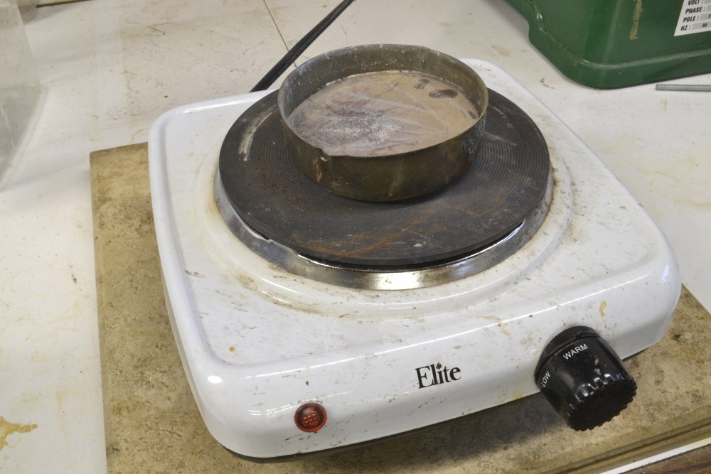
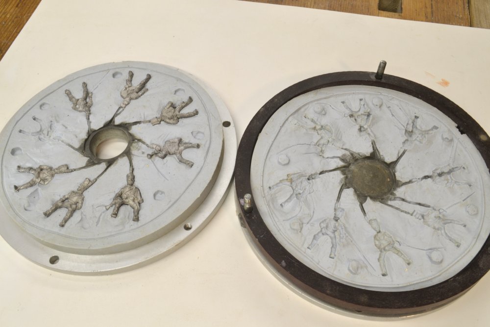
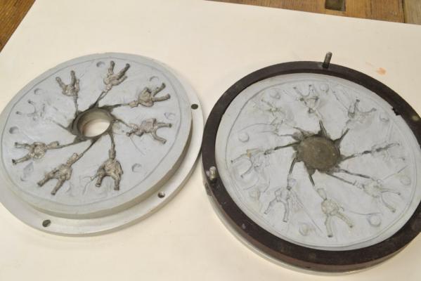
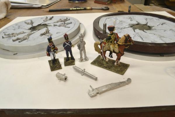
Hi Mark, I took a short break from YA this morning to take a few pictures for you. It only took a few minutes - once I found the melting pot. I use this hotplate for boiling water for wood bending. I plug it into an automatic 60-minute shutoff timer so I don't leave it on by mistake when I wander off. The first picture shows the simple pot - still full of cold metal - on the hot plate. I got rid of the arm so I would not bump into it and spill the metal. I use channel-locks to pour. I like the hot plate because you can hold the metal at a good temperature and you also have a place to toss the sprues as you cut them off. Both of these things are convenient if you are doing many pours in a session. The next picture shows the two part RTV molds in the Centricast disk. They get bolted together for casting. There are a lot of parts for the machine - to allow molds to be cast as well as castings. Note the ring around the mold joint. Some of these molds have been used for 100- 200 pours this one probably a few dozen. Finally, a few castings to show what can be done with RTV in the way of complex castings. They do not come out of the mold painted. Many of the figures have cast parts added after casting and quite a number are multiple parts. Happy casting. Ed

-
Mark, I would go with the 10 to 1, but the other might work as well for the cannons, which are quite simple. To use the 10 to 1 type, you will need an electronic scale to measure the liquid catalyst - by weight. 50/50 by volume is easier to manage. The mold tear strength was the problem for me. I found no trouble getting up to temp with the hot plate. I will take a few pics for you today and post. Ed
-
Thanks, everyone, and thank you Jerry. Since I am not using adhesive backed plates it is a simple matter of turning them over and rolling them flat. That is my fallback solution if my other ideas fail. You're right 1:72 is a lot smaller than 1:36. My pattern is fairly accurate but I need to reduce the indentation size and to do that the pins need to be a lot more regular in size and height. Matt's suggestion helped a lot and got me on what I think is a good track. I plan to try a new idea today/tomorrow. Thanks, Ed
- 3,618 replies
-
- 2
-
-
- young america
- clipper
- (and 1 more)
-
Matt, that is a very good idea. I have some syringe tubing and will have a look at what it will take. Interesting idea. Thanks
- 3,618 replies
-
- 3
-
-
- young america
- clipper
- (and 1 more)
-
I have always used a hot plate with a metal pouring dish. An electric casting pot with temperature control is the Cadillac. Agree with druxey on the plaster support for the rtv but may not be necessary for these small castings. USe new plaster of paris so the hydration goes to completion and no residual moisture is left. Micromark sells two varieties of RTV. One is better for metal - i.e. harder and more durable - I thinks its called 10 to 1. I have gotten well over a hundred castings from molds made with it. A good electronic scale is also recommended for accurate measuring of the rubber and catalyst. Oh yes, someone mentioned this I think, stir the rubber thoroughly but gently to reduce air entrainment. Oh, this brings back memories. You're certainly getting a lot of advice here, Mark. I hope some of it is helpful. Ed
-
Thank you for all of these comments. Jerry, I hear you on the plates. I had been planning to roll these flat after they were in place. However, I am looking at other methods. Rather than countersunk, I believe these 14" x 48" x .05" thick plates were prepunched pretty close to the pattern I have used , then laid over felt, then nailed with flat headed nails. this would leave a decidedly quilted appearance - not something you see on models, but certainly more realistic if it can be represented well. We shall see. Stay tuned. Thanks, Ed
- 3,618 replies
-
- 11
-
-
- young america
- clipper
- (and 1 more)
-
Amazing, Sherry and very instructive. What kind of paper are you using? Ed
-
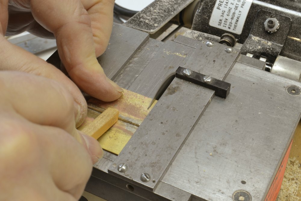
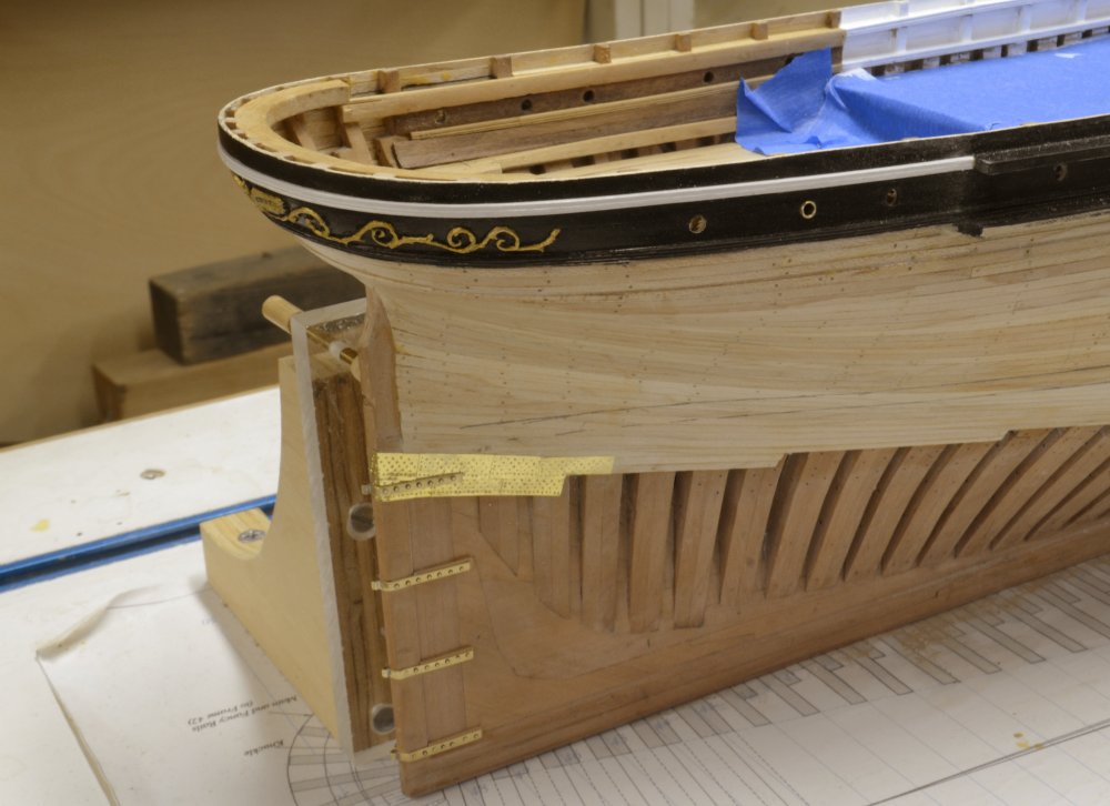
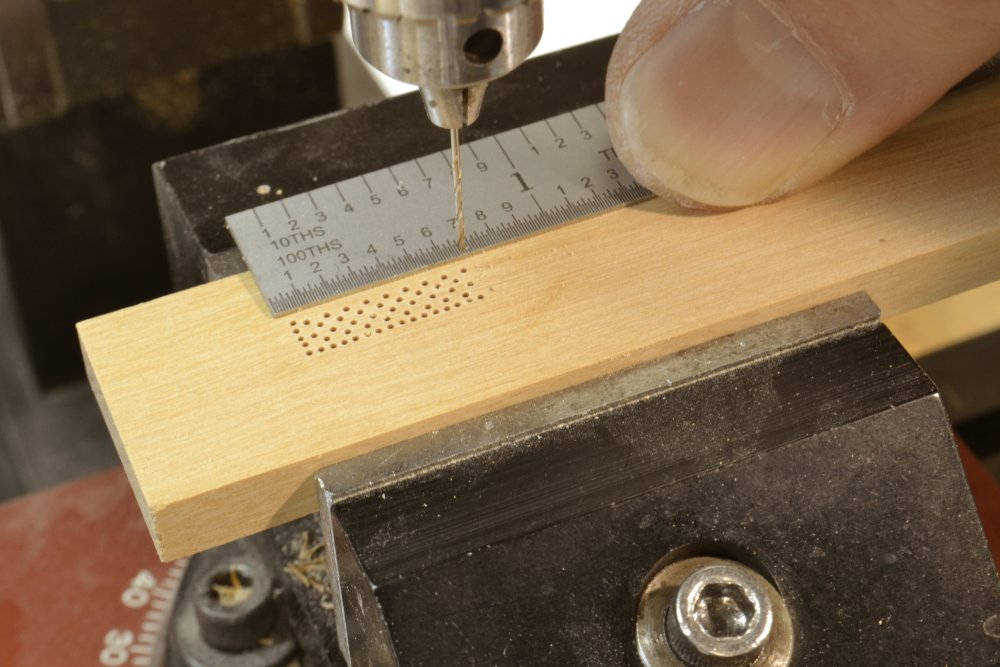
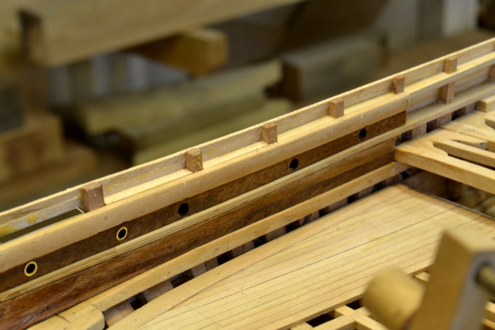
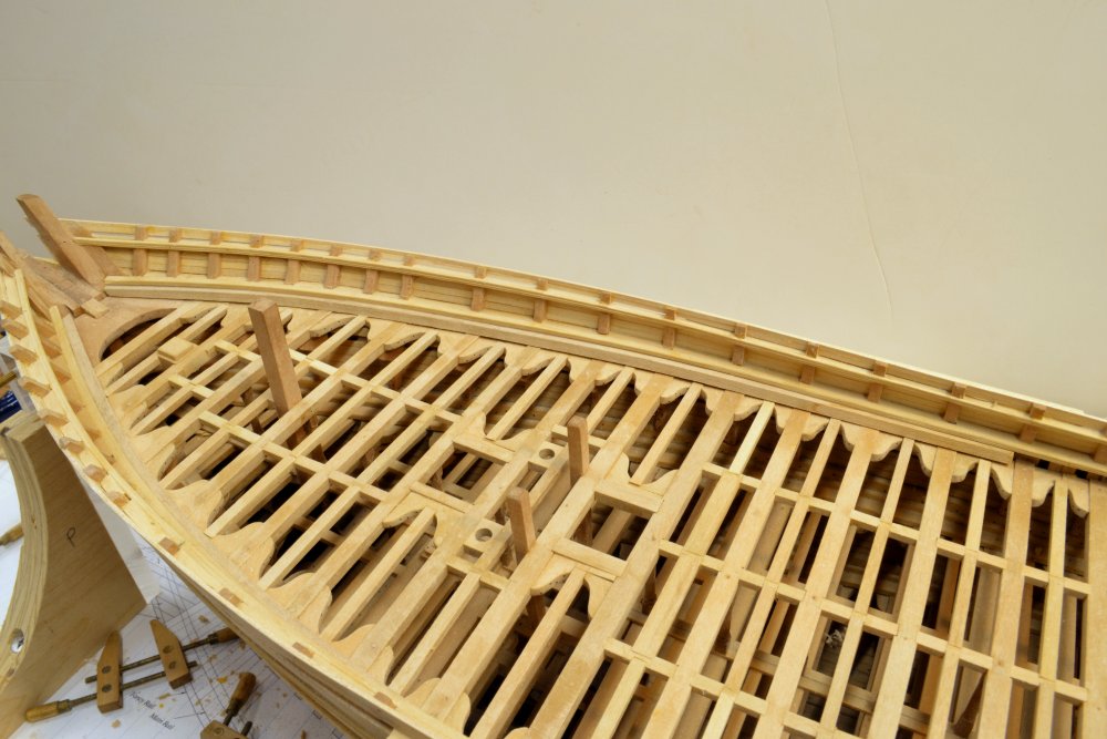
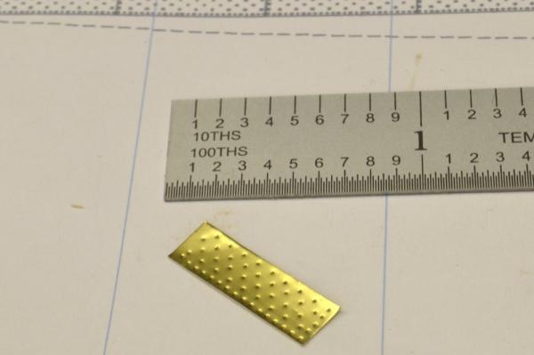
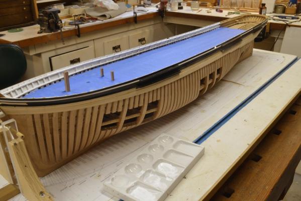
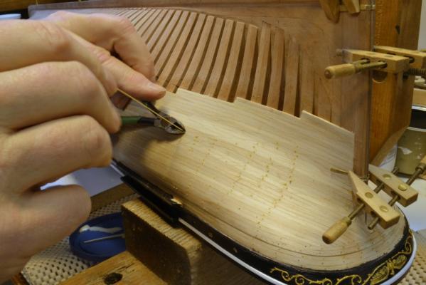
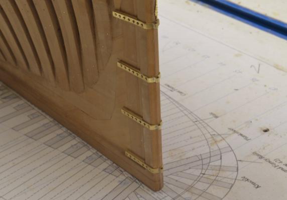
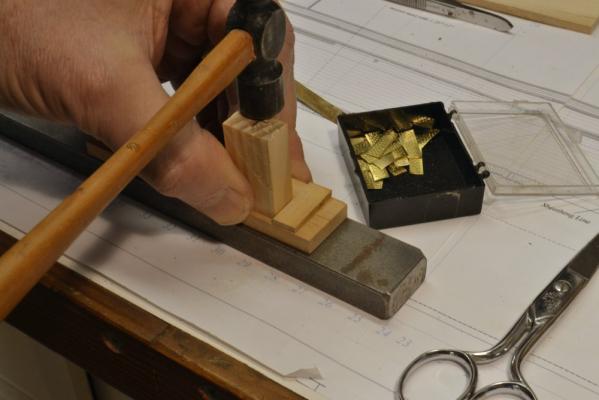
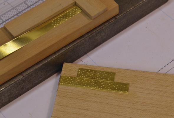
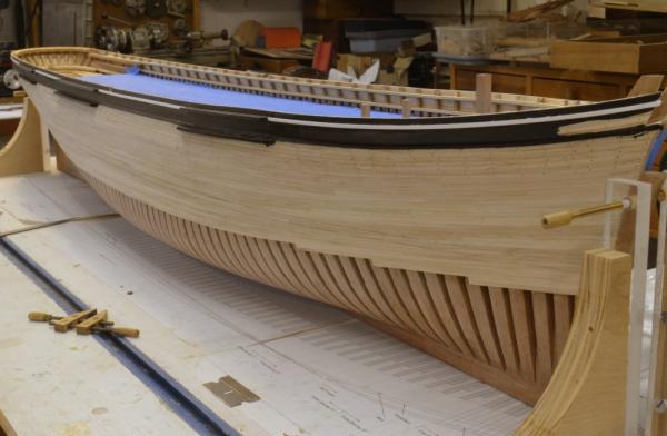
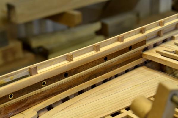
Young America - extreme clipper 1853 Part 107 – Lower Hull Work I finally finished the hull planking this week and got some other tasks well along. The first picture shows the full extent of the planking on the port side – as yet unpainted.. The deck is still masked for painting the white inside bulwarks. That work is now also finished and the installation of the painted waterways can proceed. The next picture shows some of the seemingly endless task of treenailing the planking. This work, too, is now complete on both sides of the hull. The picture also shows work on the rudder gudgeons. These were made by first silver soldering a tube into a groove in a sheet of .032” brass. The rough gudgeons were then ripped off on the circular saw as shown below. The .032” brass – about 2 ½” at 1:72 – is too thick for the straps, but allowed the thick area at the hinge to be shaped. The 6” wide straps were then bent and filed back to about 1” thick. The next picture shows the bottom four installed using small brass nails. The 16” aft face or the stern post is notched to receive the 6” wide gudgeons. These were aligned when being fitted by a stiff, straight rod through the holes. The end of the rod will mark the final center of the round helm opening – which must be on the hinge centerline. The next picture shows the gudgeons on the starboard side. The top one will be installed after this side is painted. Some of the lowest rows of “yellow metal” sheathing have been installed around the gudgeon. This will be the only gudgeon requiring this, since this is the lowest of the planking at the stern. The top of sheathing line – parallel and slightly above the load waterline - can be seen in this picture. There will be several rows of sheathing. The top row will be on the straight, horizontal sheathing line. The strakes below will follow the planking shear and “gore” into this top strake. The brass plates were cut from .002” brass. The nailing pattern was embossed into the plates used an embossing device. The picture below shows the nail pattern being drilled in a wood block to make this. The thickness of the block was sized carefully to allow small steel nails to be inserted from the underside. The tips protrude just enough to impart the pattern when stamped as shown below. Stamping these plates is almost as thrilling as treenailing. Fortunately there are only about a half-dozen rows. A close up of the first few stamped plates is shown in the last photo. After the pine stamping block “breaks in” the dimples become more regular. These are like little cheese graters. They are fastened with contact cement – another enjoyable task. After making and installing 3700 of these my Victory model, I swore I wouldn’t do this again – but that was in 1978. Ed


- 3,618 replies
-
- 38
-
-
- young america
- clipper
- (and 1 more)
-
Looking good, Mark. Casting, is an educational journey. Siggi, I am amazed at your centrifugal casting "machine". This would scare me to death without a containment to catch the flying molten metal. I invested in a centrifugal casting machine about 20 years ago and have used it many, many times - including on some 1" long cannon barrels. It has rings around the molds to prevent distortion when spinning and also to contain the inevitable escaping metal. The spinning mold is contained in a metal box with a hinged lid that has a hole for pouring - also speed control on the rotor. I have cast maybe 6000 miniature figures in this with maybe an average of 8 different figures per mold. The machine was about the cost of a Sherline mill so its not a solution for a few dozen cannons, which, by the way, may be too large. Eliminating bubbles from the mold rubber is a major headache. This was especially a problem for me with the small deep undercuts in small figures- lots of metal baseballs in eye sockets. I eventually solved it with a vacuum pump of the type used for refrigeration maintenance and a homemade vacuum chamber made from a pot and a sheet of thick polycarbonate- with some tubing and fittings - and an RTV ring gasket. I think you would be amazed, as I was, by the amount of air that comes out of RTV rubber when under vacuum. This is another investment not worth making unless you do a lot of casting. Before that I tried using a shop vac with very limited success. I found some success (before having the vacuum) eliminating bubbles in the rubber by using straight mineral spirits to dampen the pattern before pouring the rubber - instead of greasy mold release agents. Also, tapping the mold or vibrating it when the rubber is first poured may help. Dusting the mold with talc before pouring metal also helps reduce porosity in the metal castings. You might also experiment with pouring temperature. I can't offer any advice on casting resins. I gave up on them rather quickly, because of bubbles and they were too light for me. Good luck, Mark. The barrel in your picture looks great. I know you have very high standards. Ed
-
Gaetan, I can only second what others have said. The work on the stern carvings is extraordinary. Well done. Ed
- 728 replies
-
- 1
-
-
- le fleuron
- 64 gun
- (and 1 more)
-
Lovely work on the union, Micheal. When I look at the photos I keep wondering how the open crankcase and timing gear will be enclosed. Ed
-
I like that collet method as well, Micheal. Tthanks. I can only echo what others are saying - beautiful work. Ed
-
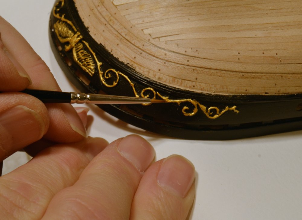
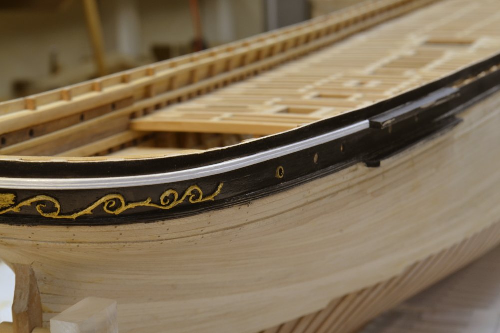
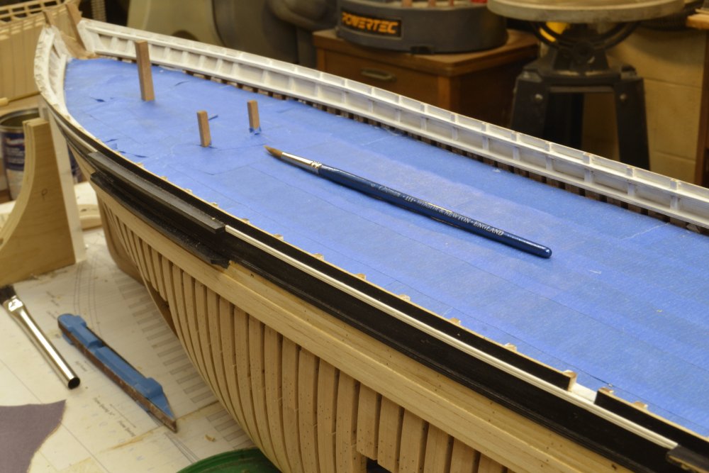
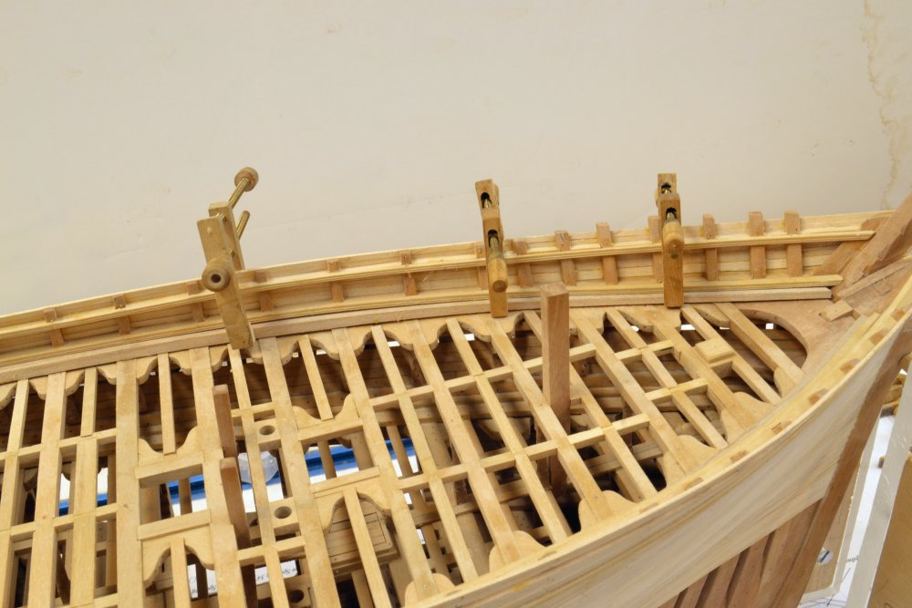
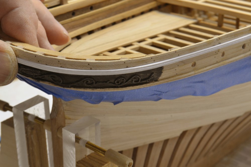
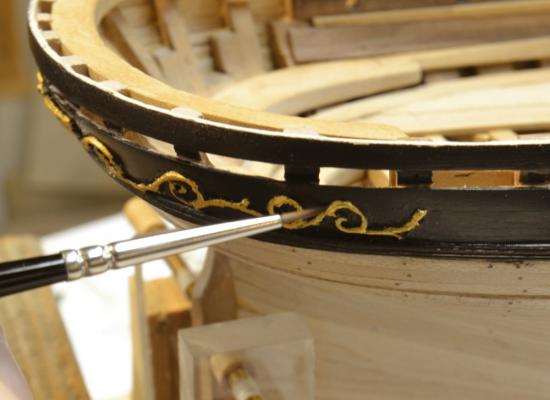
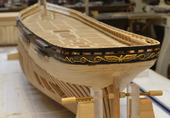
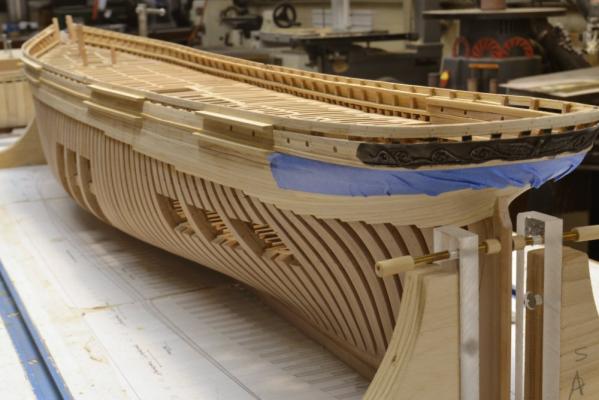
Young America - extreme clipper 1853 Part 106 – Painting I’ve always preferred to leave models in natural wood, but some of Young America will be painted. After painting the hull planking above the planksheer, the stern decoration could be painted. The first phase of that is shown in the first picture. All the paints and the sealer being used so far are various types of artist’s acrylics. The final coats will have some gloss. Most of the gold stern decoration was painted first upside down – so I could see it and steady my hand. The lines at the top were finished in the upright position as shown in the next picture. Then several more inversions to nitpick. This was a multi-multi step process – before everything looked reasonably presentable as shown in the next picture. The planking below the painted part will also be black – down to the top of the brass sheathing. I will paint that after completing treenailing. In the next picture the white main main rail around the stern is being fitted. Also one of the brass portholes is being test fit. In the next picture the stern section of the main rail is being glued in. The planking on this side is complete – just enough to anchor the deadeye chains below the lower rail. The next picture shows the completed planking on the starboard side. The planking on this side will be sheathed in “yellow metal” below the waterline. The unpainted area at the bow is left unpainted to allow gluing of the decoration carvings. The last picture shows the main deck during painting of the inboard bulwarks - the blue is masking tape to keep paint out of the structural work. The sanding and painting of this complex woodwork is real fun – several coats worth. The paint accentuates every rough area and crack. I am not too concerned about the area forward of the large vertical samson post. It will be covered with the forecastle. Also, the rack rails – pin rails – that run the full length of the deck will fit up under the upper rail - hiding some of the inboard planking. The waterway – painted blue – will fit in under the lower rail. There will be a white cap rail all along the top. Ed


- 3,618 replies
-
- 40
-
-
- young america
- clipper
- (and 1 more)
-
Good comment, Gaetan. I see you share my concern about cotton. I also agree with you on the twisting. I would add to that the importance of pre-stretching the rope after twisting it up. I should have mentioned that I tint my rope (either black or hemp) with acrylic gouache in water, dilute enough not to stiffen the rope. This might help. I don't know. I wonder if long staple cotton is more stable than garden variety thread. Comments anyone? Ed
-
I will be interested to see your results, Dave. Ed
- 3,618 replies
-
- 2
-
-
- young america
- clipper
- (and 1 more)
-
Danny, beautiful work as always. I would be inclined to fix the shrouds and not the environment, otherwise you will have the problem when you move the model or the de-humidifier isn't running. My first suggestion would be to impregnate the lines with a wax solution - microcrystalline or beeswax - very dilute in turpentine or mineral spirits. Surface wax is not attractive and the dilute solution helps with that and absorption. Some materials are more prone to this because they absorb more moisture - I think cotton being one. I would like to hear some expert comment on that. I have used linen for larger, made rope and mercerized cotton polyester for small lines - both at 1:96 - and after five years in a climate with dry winters and high summer humidity have had no problem. Some of the lines were waxed and some not. I have not used cotton because of this, but am considering it for YA, so I'd like to hear some feedback on this. Thanks, and good luck with your problem. Ed
-
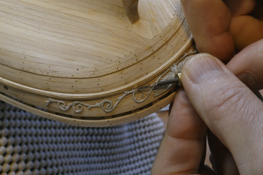
Nils, thank you for your comment and your questions. I will try to answer your questions but you will probably have to wait for the book for a usable tutorial. I have more work to do on this process before I can describe it in a way that others can follow - or recommend it. I will definitely be doing that for the book. I have a lot of history with this material and do some things intuitively. I need to translate all that into words so anyone trying to use the process will not be frustrated - especially if I provide a much better - or different - description later. However, in response to your questions: No forms were used. There are no identical parts in the decoration - mirrored yes, but no two the same. At a point in the curing cycle, the putty can be rolled into thin strings. The strings were laid to the shapes of the vines on a developed "true view" print of the decoration on a form shaped like the hull and covered with waxed paper. Small bits of new putty were added for leaves, etc. The vines at this stage were still very delicate. As they hardened they could be adjusted in shape. When completely cured they carefully were removed from the form and glued to the stern with CA. Hope that helps. Ed
- 3,618 replies
-
- 6
-
-
- young america
- clipper
- (and 1 more)
-
Micheal, I don't know at what point in time they became that flexible but similar pieces boiled for about an hour were nowhere near that pliable. I can only assume that the wood fibers were completely saturated due to the long time submerged. I am planning to use an acrylic gold paint. It does not yellow with time as other solvent based binders. I expect to do this by hand with a 00 brush with some parts dry-brushed to show the relief. I have started doing some testing for that. The figures at the bow may be more interesting. They were completely different on each side and painted in natural life-like colors - according to Crothers. Ed
- 3,618 replies
-
- 5
-
-
- young america
- clipper
- (and 1 more)
-
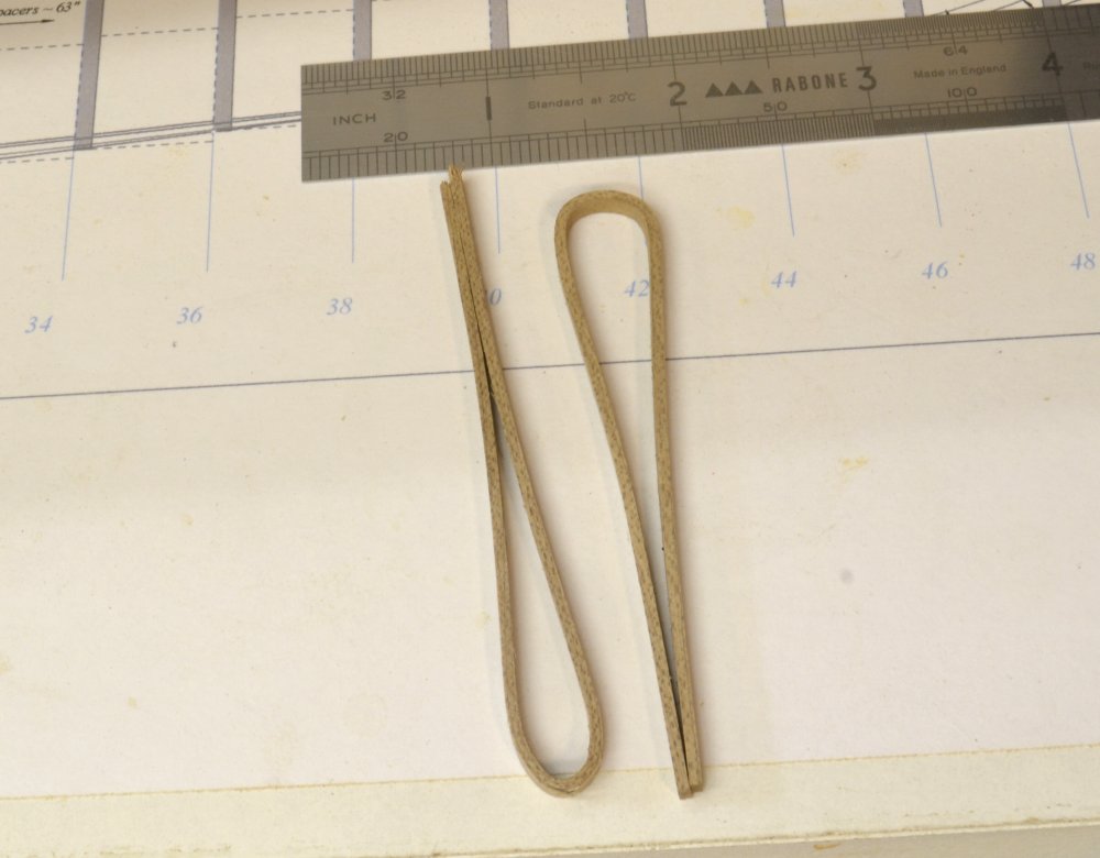
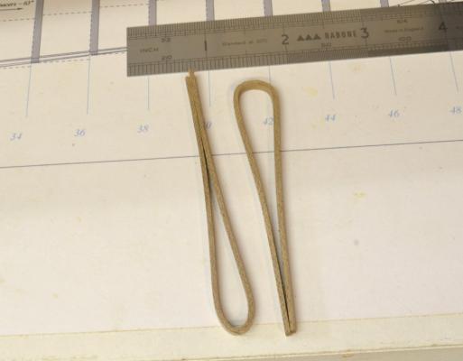
Thank you all very much. I had my doubts about using the sculpting material on the vinery, but could think of no other solution that I had any comfort with. As it is I believe they could be finer, but who knows what the original looked like. From one of the photos, it certainly appears that the eagle had some depth to it. The material is hard when cured but fairly brittle in these small fine pieces. The product is Magic-Sculpt. It is a two part epoxy putty made for sculpting. It hardens gradually over about 24 hours and is workable in different ways at varying hardness stages. It adheres fairly well to itself, but at times I have had to use CA for some parts. I started using this 15 or 20 years ago to make original patterns for casting 1:60 military miniatures and also for some larger 54mm scuplted figures. It is a very versatile sculpting material, but takes some time to learn how to use it well. I use the natural colored material. I tried the white and it works completely differently. I also tried several other similar products. It has a long shelf life. I think its a great product. For bending, I actually immerse the wood in boiling water until it is sufficiently pliable. I have tried other methods but keep coming back to this. When completely dry the pieces stay bent and can be sanded to their normal finish. I have found that being able to bend a shape is more a question of when rather than if. The two maple strips below were bent to these shapes after I found the straight strips in the bottom of my pot. They were probably in there for a week through several boiling cycles. The u shaped rail around the stern (6" = .08" square maple) shown in the last post was probably boiled for 45-60 minutes.
- 3,618 replies
-
- 20
-
-
- young america
- clipper
- (and 1 more)
-
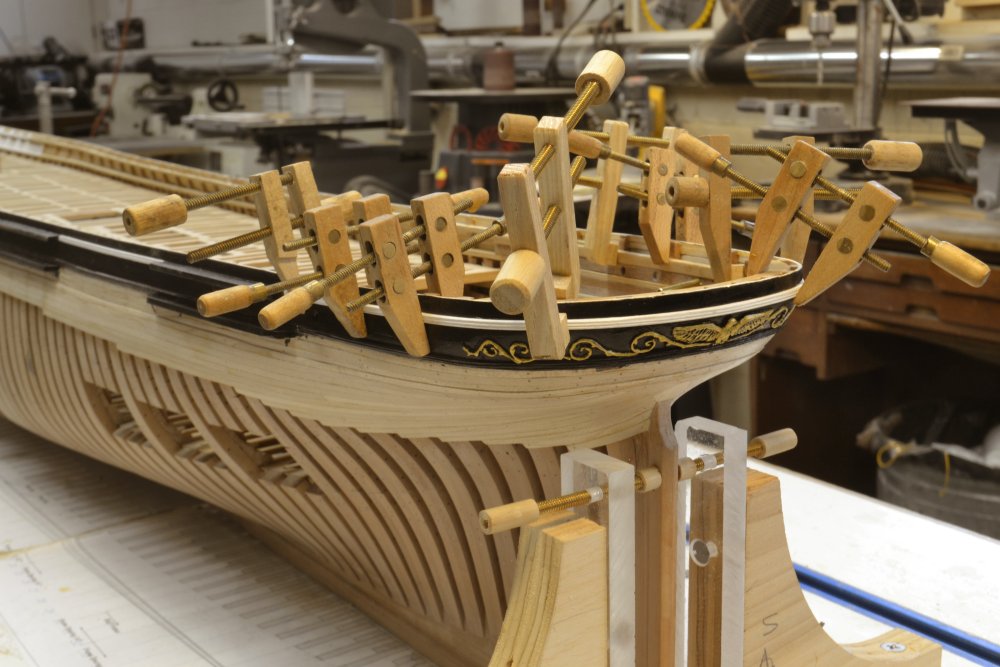
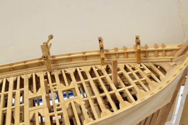
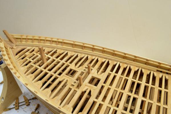
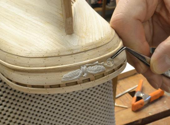
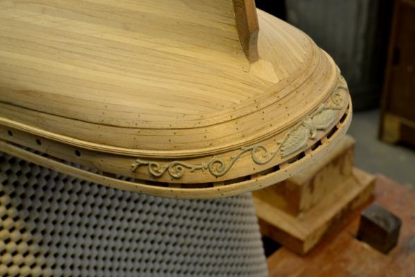
Young America - extreme clipper 1853 Part 105 – Planking and Wales continued The exterior planking is now finished – except for treenails. The next phase of work will involve a lot of disparate tasks to prepare for the work on the main deck. There is much to be done before that can start. In the last post, I showed the cabin lights being drilled through the outside planking. The first picture shows the inboard planking on the cabin deck with the holes and two temporary brass ports fitted for size. The cabin deck will house 19 cabins, two WC’s and an open central area – plus a staircase from the main deck. All of this is speculative but very typical of the class. Cabin finishes were usually quite ornate – no holds barred on fancy woods, gilt, carvings, etc. I don’t intend to go overboard on this, especially without any historical data, but I expect to panel the partitions, fit built in bedsteads and some cabinetwork. This will come later but I wanted to make a choice on wood. I am assuming mahogany and intend to represent it with black walnut as shown above. It has the look of old Cuban mahogany – to me at least. except for the above, this will all come later. While the model was upright, the waterways were made and fitted. In the next picture a forward segment has been boiled for bending and is drying. These will be pre-fitted with scarphs, but cannot be installed until the bulwark interiors are painted. The next picture shows the starboard forward section after drying – just prior to making its joint with the next segment. The painting order is dictating events at this stage. First the outboard planking above the planksheer will be painted black, The white main rail will then be installed, allowing the inboard bulwarks to be painted white. The blue waterways can then be installed and work can proceed on the main deck – a lot of complications to avoid painting different colors on adjacent areas after assembly. The next picture shows work that is necessary before painting the waist planking. The eagle and the vinery on either side are made with epoxy sculpting material. (I could never manage this in wood.) When cured, the material is very hard, but brittle - so the work is done in two steps. In the first step the rough sculpting shown above was done on a curved form so the parts could be removed and fit on to the stern without bending. The next picture shows the carving work glued to the starboard side. Once glued down the carvings could then be further refined with small tools as shown below. This work mostly involved thinning the greenery to be more delicate. All of this relief carving will be gilded. The next picture shows the finished planking on the port side. The planking to be painted first is above the lower channels. At this stage those areas are being sealed for final sanding. Masking tape will keep the paint confined above the planksheer for now. The stern carvings have been primed with black to make sure the black acrylic adheres to the epoxy. In the last picture the main rail around the stern has been painted as a test and is being fitted into its slot – just temporarily until the surrounding black is painted. So – a lot of niggling little tasks to break up the monotony of treenailing – but progress nonetheless. Ed


- 3,618 replies
-
- 42
-
-
- young america
- clipper
- (and 1 more)
-
Christian, I am using hard maple for the planking that will be painted. I would not use it for unpainted surfaces because of the grain color variation, but it is hard, can be sanded very smooth and bends well. It is also less expensive, but I have many small pieces leftover from other woodworking projects, so it was an easy decision. Ed
- 3,618 replies
-
- 1
-
-
- young america
- clipper
- (and 1 more)