HOLIDAY DONATION DRIVE - SUPPORT MSW - DO YOUR PART TO KEEP THIS GREAT FORUM GOING!
×


EdT
-
Posts
2,213 -
Joined
-
Last visited
Content Type
Profiles
Forums
Gallery
Events
Everything posted by EdT
-
Mayflower by SawdustDave - Finished
EdT replied to SawdustDave's topic in - Build logs for subjects built 1751 - 1800
Nice work, Dave. Also love the sign. Ed -
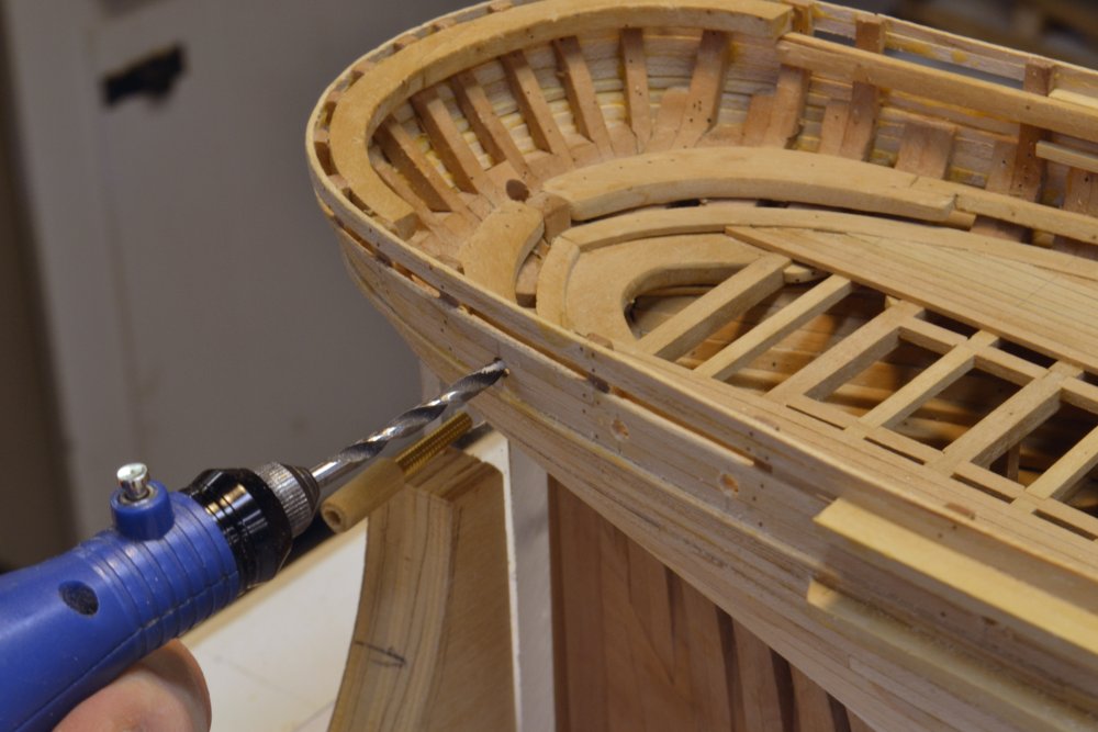
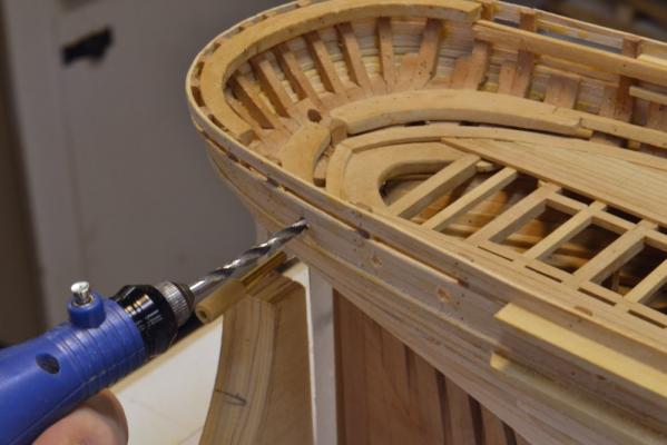
Thanks for the comments and questions. Let me try to answer those. Peter, there was no spiling needed on any of the outboard planking and in fact very little on the ship so far. I am more of a boiler/bender than a spiler, but there was some spiling on Naiad - at least on the waterways forward as I recall - and the method I use for that was covered in Volume II. Many of the planks on the YA stern required bending. That process was mentioned in earlier posts but will be covered more thoroughly in the YA book. Also, there was some spiling - my style - for the inboard deck transom work. I may have briefly described that in an earlier post but that too will be covered - as will all the methods used on the model.. Micheal, very good question. Tear-out is an issue, particularly on the backside. The brad point drill at high speed can eliminate it on the front side but it still occurs on the back side. I would normally use a block - even to the point of gluing it on - as I may do for the scuppers that will be drilled through the waterway from the inside - but for these port holes through the outer planking I was not concerned because there will be inboard planking concealing it. I did drill through the inboard planking from the outside through the outer holes, starting with double thickness inboard plank clamped in place, then after drilling removed it and ripped off the inner face on the circular saw to give a clean surface. I will show a picture of the inside on the next post. Cheers, Ed
- 3,618 replies
-
- 8
-

-
- young america
- clipper
- (and 1 more)
-
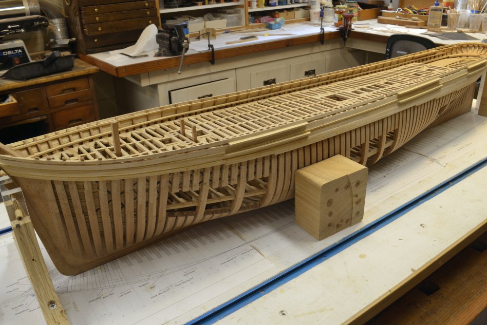
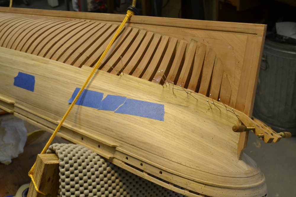
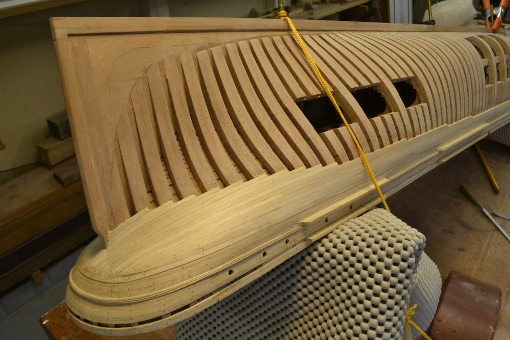
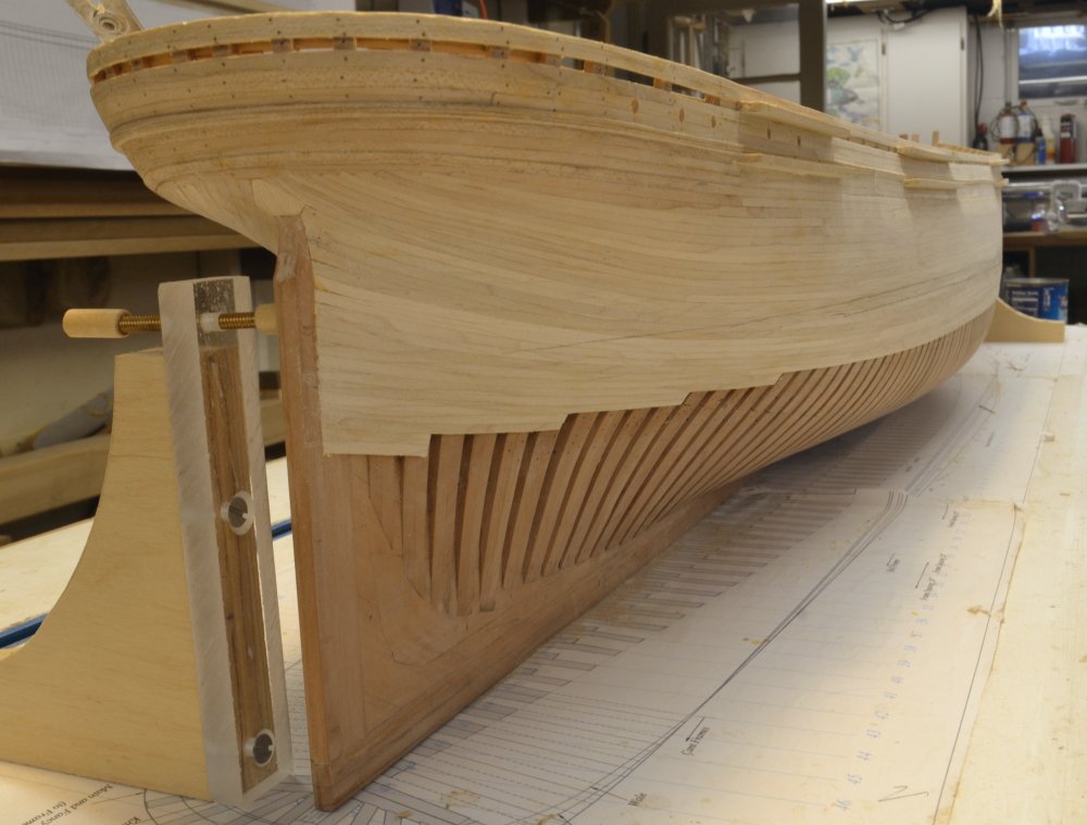
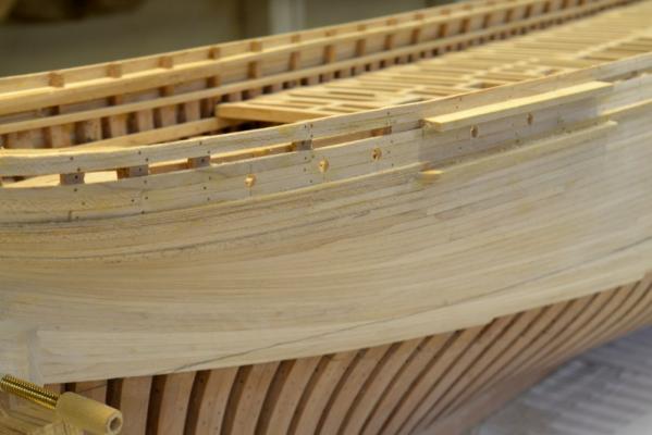
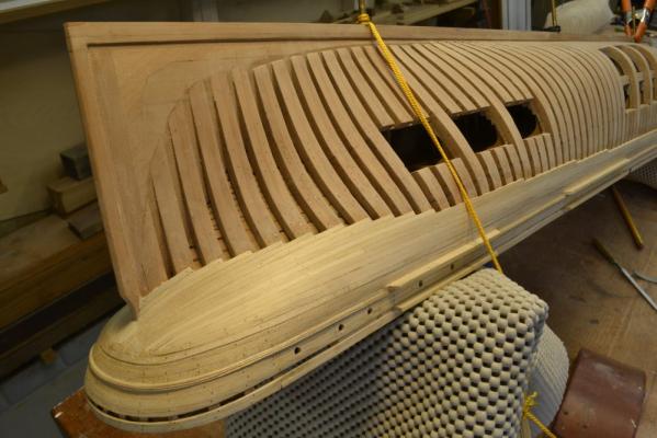
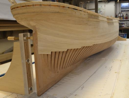
Young America - extreme clipper 1853 Part 104 – Planking and Wales continued In the first picture the model has be uprighted and plumbed so the load waterline could be marked. I needed to do this to set the extent of planking on each side. The wood block is my gauge. This was also a good opportunity to mark out and bore the holes for the cabin lights as shown in the next photo. The inboard finish planking was also installed and bored out. I will show this later. Brass tubes through to the interior will be added later. The next picture shows the five openings on the starboard side. Planking has progressed downward in this picture – below the bottom of the wale – but there is still more to be added. In the next picture the hull has again been inverted to complete the planking. In this picture the aft planking is being stepped back with two strakes at each step on the starboard side. This will permit several strakes of brass sheathing – each two planks wide to be wide to be installed later. The sheathing band will extend to the edge of the lowest planks. The top strake of sheathing will be on the waterline, with the strakes below parallel to the run of the planks and gored into the top strake. On the port side there will be no sheathing and the planking will end higher to leave the framing exposed. This planking is stepped back higher up as shown again roughly parallel to the LWL – in single strake steps on this side. Some planking is needed on this side so the deadeye chains can be fixed and also to provide a nicer view of the finished stern – at least from the starboard quarter. In the next picture the hull has been uprighted again. The planking of the starboard side shown is complete. The strakes below the 20 wale strakes diminish down from the wale thickness of 6” to the 4” thickness of the common bottom plank. This transition is barely perceptible. The top of the sheathing line can just be made out in this picture. I can’t explain why, but seeing this expanse of planking makes one realize just how large this ship was. This was not as pronounced when the hull was in frame. Ed


- 3,618 replies
-
- 45
-
-
- young america
- clipper
- (and 1 more)
-
Thanks, again everyone. Alan, that's what I call a commitment - most appreciated - especially if you found something useful. Rob, the second model is a 1:96, POB version of Young America. Its a demonstration model for the forthcoming book. I should have some more to post soon - maybe today. Ed
- 3,618 replies
-
- 1
-
-
- young america
- clipper
- (and 1 more)
-
Your comments and the 40 likes leave me pretty speechless - so I'll just say thanks.
- 3,618 replies
-
- 5
-
-
- young america
- clipper
- (and 1 more)
-
Micheal, I'm with you on the risks in repetitive work. I don't like it much because my mind really likes to wander. Unfortunately, there is plenty of it to be done in this work. My hat continues to be off to you on this engine. I can't wait to see a video of it running - I'm sure you feel the same. Cheers, Ed
-
Good to see you back, Sherry. Very nice work on the guns. Ed
-
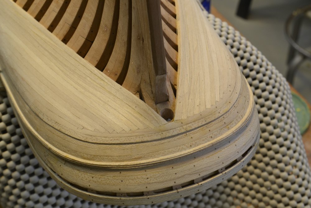
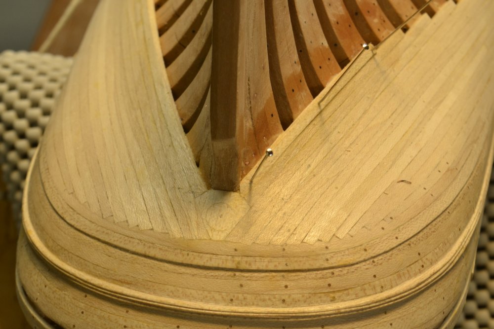
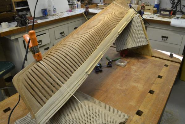
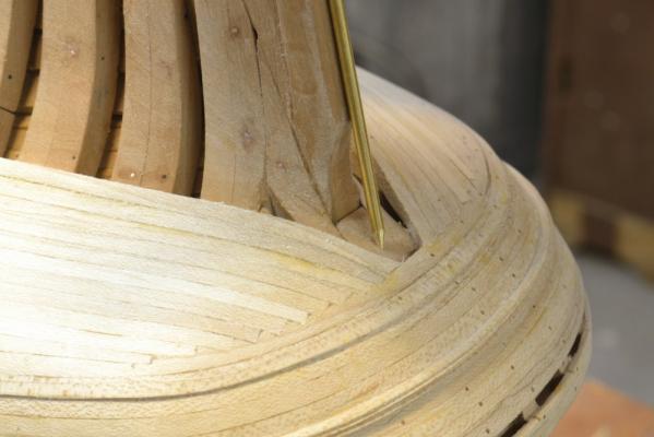
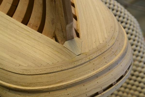
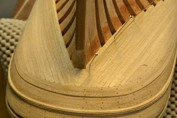
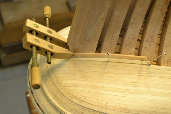
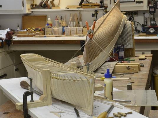
Young America - extreme clipper 1853 Part 103 – Planking and Wales continued The work proceeds apace. Post-holiday lull and the winter weather helps. Work on the lower hull requires either some gymnastics or some other support for the model. The first picture shows the simple setup that allows the model to be tilted as needed – a very un-shipyard-like look. The wale on this side is about one-half planked in this picture. The next picture shows the wale planks converging at the lowest perimeter strake at the stern. The brass rod is the diameter of the gudgeon eyes and is being used to mark the center of the helm port by laying it on the sternpost. In the next picture a hole for the port has been roughed out. The rudder head was round and was encased at the port in a sleeve – wood or iron – to prevent ingress of water. The diameter of the rudder shaft was 16” – matching the sternpost. With the sleeve the opening will take up much of the area as yet unplanked. I decided to fill the area with a single chock as shown in the next picture. A circular opening for the sleeve and rudder head will be cut through this later. In the next picture the hole has been centered. Additional wale strakes are being added in this picture. In the next picture the final piece on the port side has been boiled and is being fitted to dry. The planks on this side are being stepped back at each frame to allow the stern area to be completed without adding more strakes on this unplanked side. Hence these last two pieces are very short – the lowest will be half the length shown. The next picture shows the final wale strake in place at the stern on the starboard side. This side will be planked down below the waterline so there are more strakes to be fitted at the stern. These will diminish down to the thickness of the common lower planking. I don’t want to use this forum to pitch the forthcoming book, but I feel that a few words are in order, since several people have asked about it. Bob Friedman of Seawatchbooks and I were both quite enthused about a book on American clipper ship modeling. We both felt this was a neglected area. However, I had some concerns about another “full framing” methodology book that would be a rehash of previous material. I was also concerned about writing a book about a large, fairly advanced structural model that would probably appeal mainly to a small slice of experienced modelers. It took some time for me to resolve these issues and decide to write the book – two books hopefully – the first on modeling the hull and the second on masting and rigging. Like the Naiad books – and unlike this build log – the books will be very heavy on methods – I like the word processes. As work on YA progressed, the processes used were both different enough and in some ways unique and this allayed some of my concerns about redundancy. However, I still wanted to reach a broader range of modelers – specifically potential or less-experienced scratchbuilders looking for a foothold and some help on methods. To this end the book will also include methods, drawings, text and pictures for construction of a smaller, simpler POB version of the model. The processes developed for this model are designed to provide a basis for advancement to fully-framed modeling using the upright, shipyard-like, methods that many of us favor. The planned volume on rigging – if we get that far – will apply to both versions. Simpler tools, fewer fancy devices and readily available materials will also be used for the POB model. To support this important content, a second, 1:96 POB model is being constructed. Until making the book decision, I have been careful to exclude this from posted pictures but that precaution is now no longer necessary so I will show one picture of the current work area with both models in progress. Although having two models in the shop has exponentially increased the clutter, the biggest problems are keeping the two scales straight and using the right drawings – and getting all the work done on schedule. Ed


- 3,618 replies
-
- 57
-
-
- young america
- clipper
- (and 1 more)
-
Thanks, as always. Yes Allan, spring clamps must sometimes be resorted to. They don't look as nice in pictures but sometimes they are needed. Christmas is a long way off, so don't despair. I do know the feeling. Ed
-
Very intricate and precise work, Micheal. Very impressive. Do you intend to harden the cams and followers for wear resistance? It would be quite easy to do. Ed
-
Bruce, I've missed seeing your postings. Welcome back. Lightning looks great and her boats are fantastic. Very good idea to use metal for the small breakable parts - especially as we get older and lose control of our hands. Even though our cats have passed on, I wouldn't dream of rigging one of these without a case. Unfortunately, my dismantled Victory case is going to have to be enlarged for YA. I cannot discern the bullseyes. Where have you used them in place of deadeyes - and do you have a source for when the change took place. I'm also still looking for a supplier of teeny tiny chain for halyards et al. Any ideas? Ed
-
Great point, Mark. Knowing that the builders would have found a way to make it all fit together properly allows you to proceed with some faith - assuming of course that the underlying work is done as intended. This was certainly the case in the YA stern planking. The solution became fairly obvious - not necessarily easy - but pretty obvious. Ed
- 3,618 replies
-
- 2
-
-
- young america
- clipper
- (and 1 more)
-
Great precision, Mark. What do you intend to cast these in? Have you thought about shrinkage? With all this accurate work, you may want to research a low shrinkage alloy. Also, if you cast these vertically in RTV you may get some swell at the bottom.- but this may not be an issue with the size of these - I assume about 2" long. If you use pewter you may want to get an alloy that has some bismuth added to reduce shrinkage. Knowing your thirst for precision..... Ed
-
Congratulations on the dry test. Fantastic work. Ed
-
Thanks, again everyone. Walter, the work you asked about was going on as I got your post, so there will be something in the next part. Thanks for the question. Ed
- 3,618 replies
-
- 1
-
-
- young america
- clipper
- (and 1 more)
-
I agree with Druxey on option 1. Ed
-
Thank you, everyone for all of the comments, "likes" and New Year wishes. I am most appreciative. The work on the stern planking has been very interesting. I have worried for some time about how it would all fit together, but as the structure developed the clarity of the original design emerged. It was simple and elegant and not too hard to model - just time consuming with the one step a day process of boiling, bending, clamping, drying, gluing, pinning and then leveling. It should be finished by the next post. I should probably say a few words about the new book. Many of you have mentioned it in the past. Perhaps in the next YA post. Doris, I am happy to hear of your new job. You must not let it interfere too much with your remarkable modeling work. We would all be devastated without your posts. Ed
- 3,618 replies
-
- 3
-
-
- young america
- clipper
- (and 1 more)
-
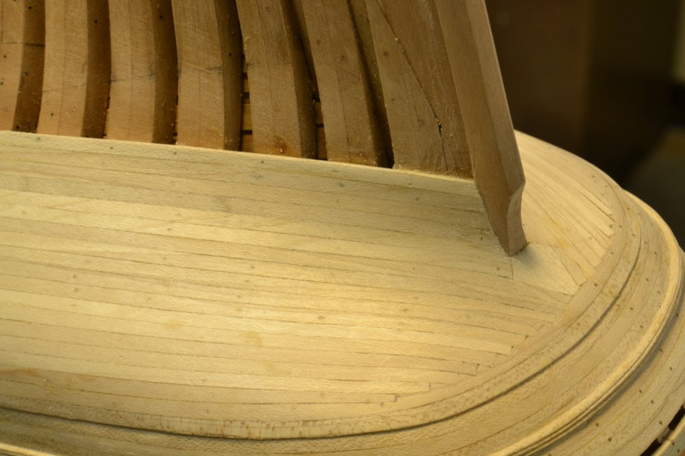
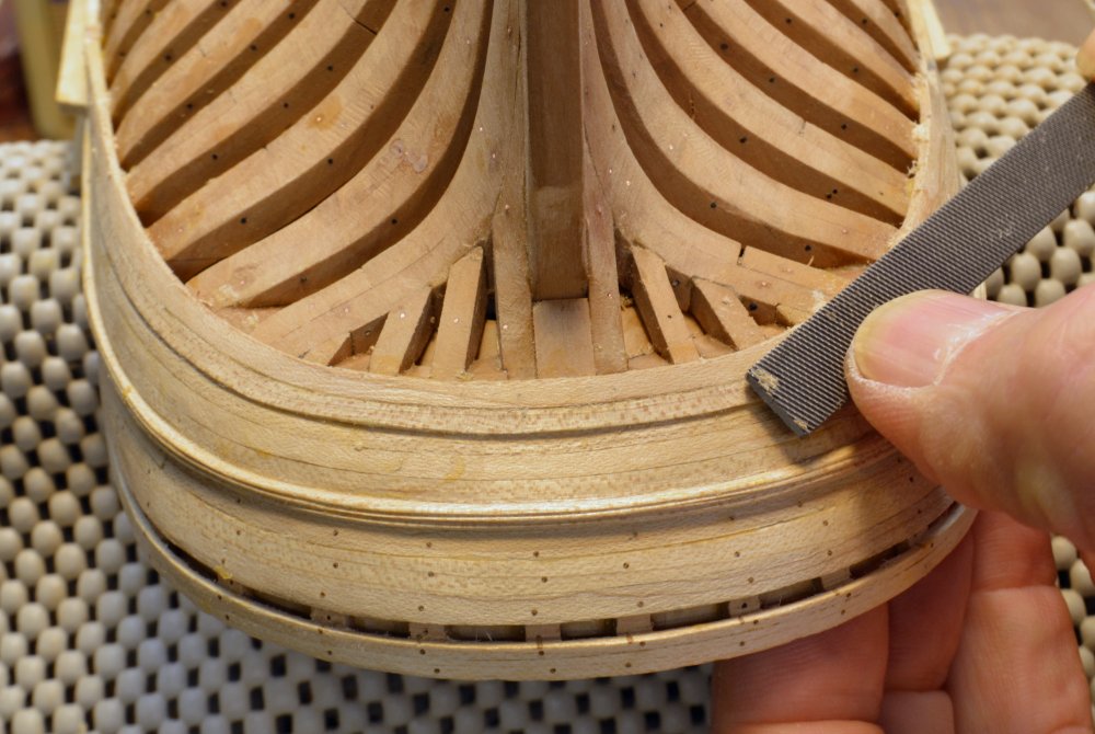
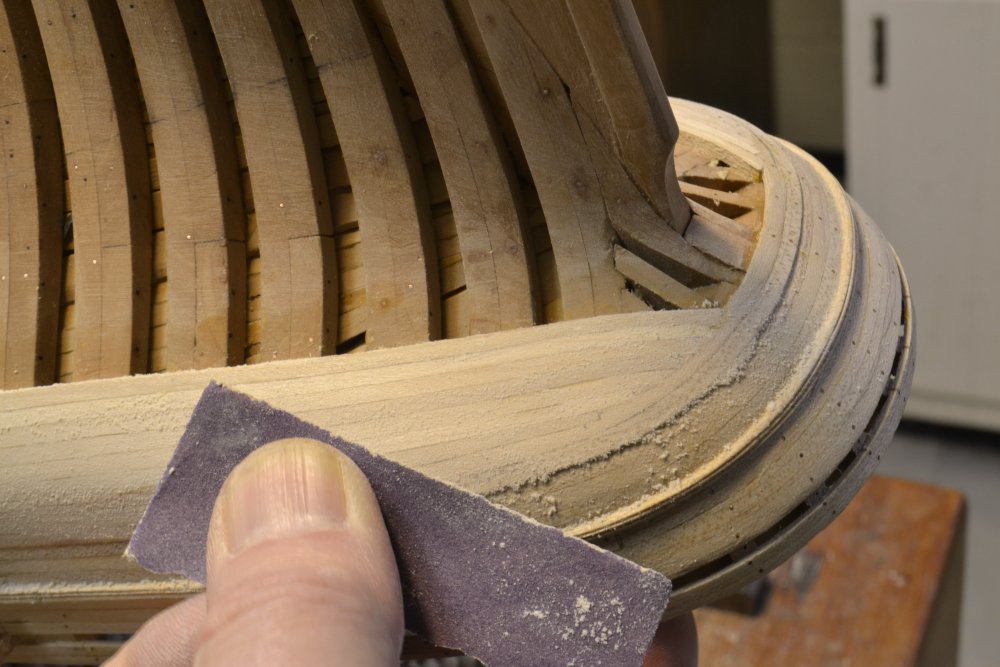
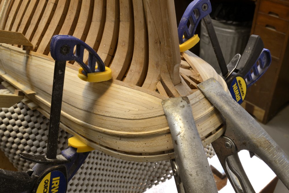
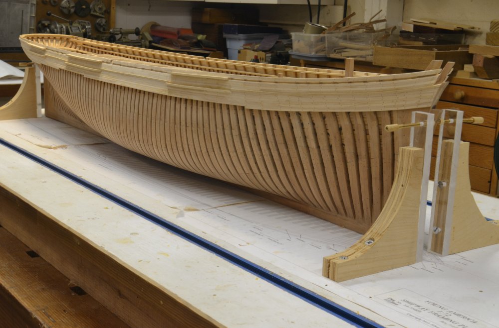
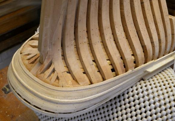
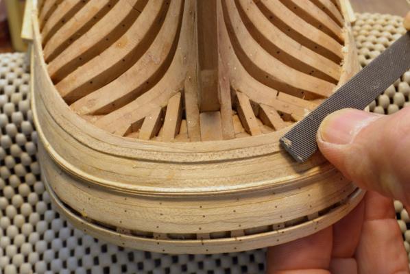
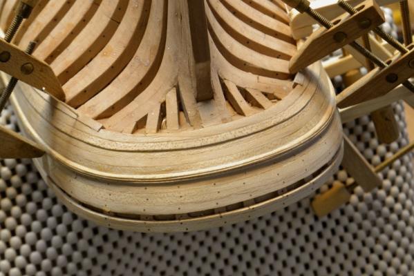
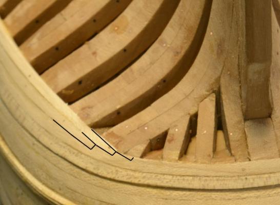
Young America - extreme clipper 1853 Part 102 – Planking and Wales continued With the announcement of the forthcoming book(s) on this model, I’ve got to keep my nose to the grindstone – giving up some of the leisure I enjoyed before making the book decision. So much to do, so little time. In the first picture the wale upper strake around the stern has been installed. All of the wale planks are 6” x 6”. This first strake transitions in thickness from the 4” common plank thickness. In the next picture the first full thickness wale plank has been fitted around the stern and is being levelled off with a file. Some of this levelling was required on all planking but especially around these curves. The planks were slightly oversized to allow for this. This wale plank borders right on the “knuckle” – a transition point in the aft hull shape. Planking below this will butt into this strake as shown in the next picture. The two strakes shown above will be pared down to half width after gluing. There are chocks between the stern timbers to allow the ends of the lower strakes to be bolted. Lacking documented practice, I have assumed that these planks would be cut into the last circumferential wale plank as shown below. This was the common practice for the ends of planks that butted into another plank where the angle would require excessive tapering of the planks. Maintaining a minimum of one-half the width and cutting into the margin plank as shown above would permit these joints to be caulked. This could not be done with a full taper on the planks. Additional planks have been added in the next picture. In this picture the surface is being sanded with 220-grit paper in preparation for treenailing. In the next picture additional strakes on either side have been boiled and clamped in place to dry. These planks do not have the extreme curvature of the circumferential planks but do curve up at the ends and twist to follow the hull shape. The last picture shows the starboard planking while the ship was uprighted for some dimensional checks – and for inspection by Christmas visitors. A lot of exterior planking remains to be done – down below the waterline on this side and a few strakes below the channels on the port side. There are about 20 strakes in the wale itself plus some diminishing strakes and common plank below that on this side. Ed


- 3,618 replies
-
- 50
-
-
- young america
- clipper
- (and 1 more)
-
Thank you for the support for the upcoming book(s). We have a lot of work to do to get it ready by fall. Ed
- 3,618 replies
-
- 1
-
-
- young america
- clipper
- (and 1 more)
-
Micheal, Thanks for the tutorial on drilling. I particularly appreciate the comments on indexing to locate holes. I am doing a lot of small hole drilling in wood right now on Young America's planking. Tight holes to hold the planks with pins when glued are #74 and holes for the treenails #73. There are literally thousands of these on the model. I always - always - center mark the wood with a sharp scriber and use a hand-held, pencil sized (Wecheer) rotary tool with either steel or carbide bits in a zero opening (Dremel) collet. As I write this I am fiercely knocking on wood but I have not broken either of the two bits I am using in several months. The usual cause of breakage for me is dropping the tool or whacking something with it. I believe the keys are those you mentioned - center-marking, high speed, keeping bits clear - also, a very light touch with the tool helps. I too, will be keeping a copy of your note. Thanks. Ed
-
Thanks, again, everyone. Elia, there are actually two photos. I don't know the dates - 1860's/70's I would guess. Snow courtesy of Paintshop Pro. Ed
- 3,618 replies
-
- 2
-
-
- young america
- clipper
- (and 1 more)
-
Thank you all for your comments and continued support. Ed
- 3,618 replies
-
- 1
-
-
- young america
- clipper
- (and 1 more)
-
HMS Naiad 1797 by albert - FINISHED - 1/48
EdT replied to albert's topic in - Build logs for subjects built 1751 - 1800
Wonderful work, Alberto. Merry Christmas to you! Ed -
Thank you, Nils. The clamps in this picture were either made especially for this task or modified from others. Although I have a lot of small clamps, none seemed to work well for this. The clamps are hardwood with soft jaws, to keep from damaging the softened boiled wood. As far as single planking is concerned, I am trying to duplicate the construction of the original as far as it is known, so all the frames are correctly sized as are the planks - 4" x 6" wide for the common planking, 6" x 6" for the wale. I am using maple for this planking because all will be painted and - if straight grained - it bends easily. Also, I have a tons of hard maple cutoffs from past furniture projects. Ed
- 3,618 replies
-
- 3
-
-
- young america
- clipper
- (and 1 more)