EdT
-
Posts
2,214 -
Joined
-
Last visited
Content Type
Profiles
Forums
Gallery
Events
Everything posted by EdT
-
Rob, I am away at the moment so will not be able to answer your question for a few days. Ed
- 3,618 replies
-
- 1
-

-
- young america
- clipper
- (and 1 more)
-
Thanks for the comments and the tips. Walt, the clamps are homemade. There is some descrition in my Naiad build log and there are dimensioned drawings and a complte description inmy book - The Naiad Frigate, Vol I. See the links below. Ed
- 3,618 replies
-
- 1
-
-
- young america
- clipper
- (and 1 more)
-
Thank you all for these comments. Thank you, Daniel, for posting the pictures. I love old shipyard photos. The clutter and seeming confusion reminds me a lot of my workshop. I believe those framing platforms were often set up fore and aft of the first erected frames, then moved as the erection progressed. I wanted to mention in the last post, that the four stem pieces were the second set to be made. The first set were slightly undersized, something I did not notice until matching them to the drawing. The reason for this was that the pdf printing was set on "shrink to fit oversized pages" instead of "actual size" - a very slight difference. I usually eliminate this issue by making sure the drawing does not need to be shrunk to fit, but on these early sheets I often don't get those checks made. I am well versed in all of these Adobe software settings, having wrestled with them - endlessly it seems - to get all of the Naiad CAD drawings published at the right scale and page size on pdfs. However, eternal vigilance is required. Settings carry over from the previous print job, so it is easy to print at the wrong scale. I mention this as a reminder to always check through the print settings when printing patterns or drawings from pdfs. Save yourself some work - and material. Hope this helps someone out there. Ed
- 3,618 replies
-
- 4
-
-
- young america
- clipper
- (and 1 more)
-
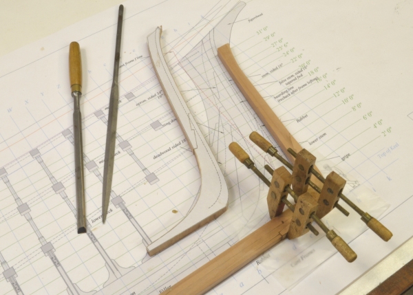
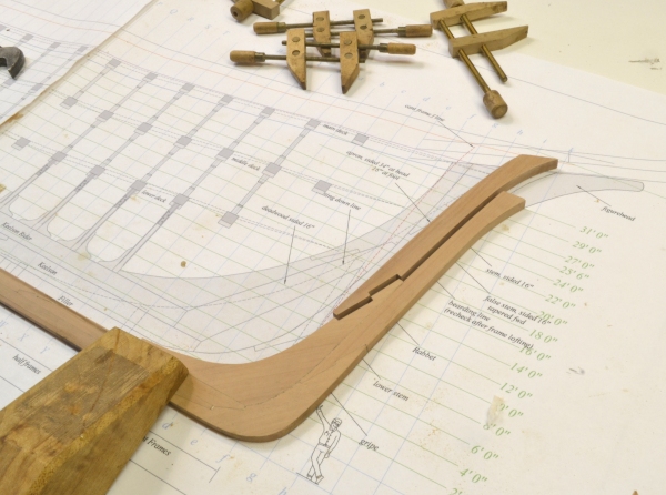
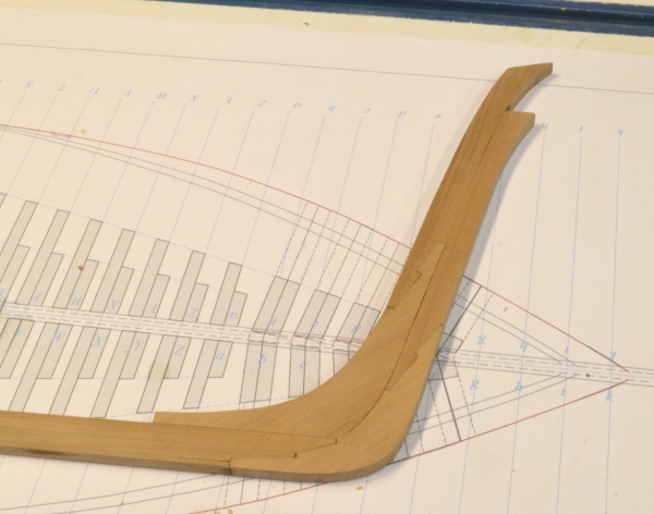
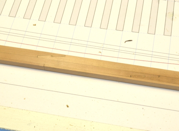
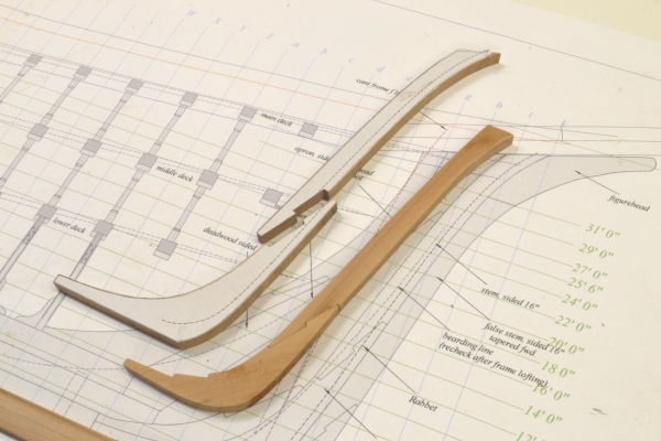
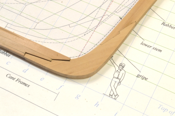
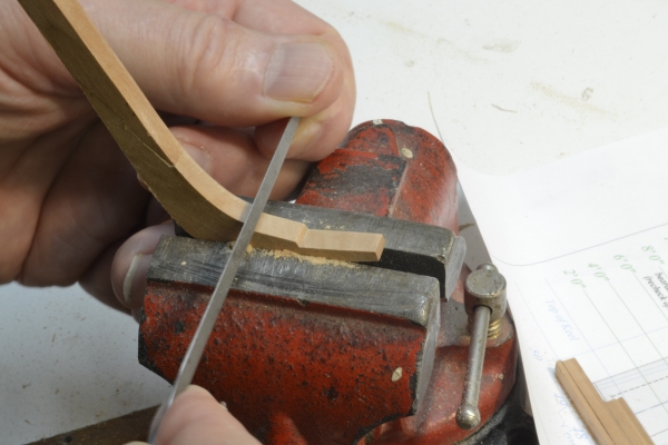
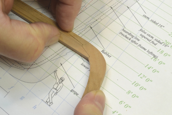
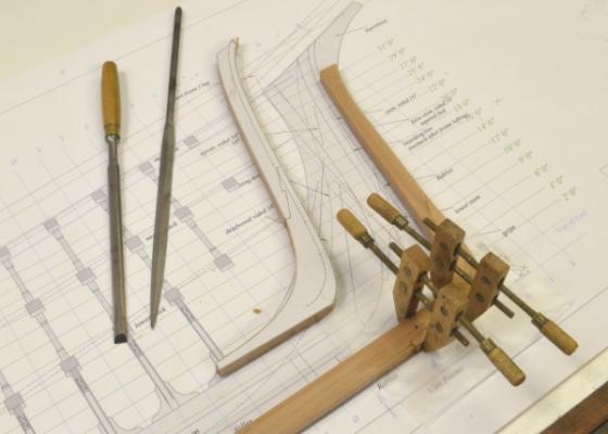
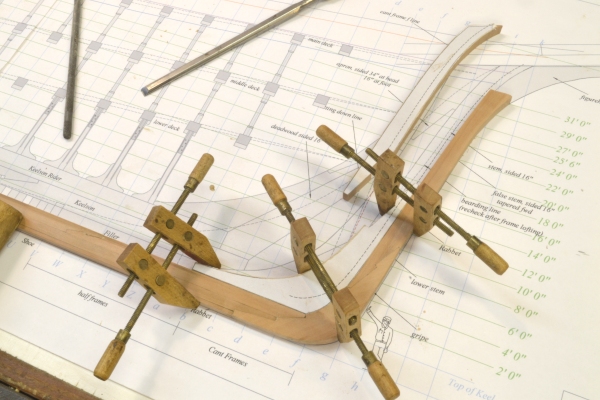
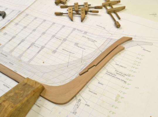
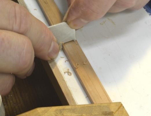
Young America - extreme clipper 1853 Part 7 – Stem and False Stem I decided to do the stem next because I still have some checking to do on the drawings of the sternpost. The first picture shows the four pieces involved. They are all sided 16" - same as the keel. In this picture the gripe and the false stem have already been assembled. Once the pieces were cut out and trimmed to their final shapes, the patterns were removed to permit close fitting of the joint. The two stem pieces in this picture have been cut to “almost” final shape and still have their patterns attached. Once the assembled forward assembly is fit and attached to the keel the stem pieces will be added – lower stem first then upper stem. The next picture shows the connection to the keel assembly – not yet fit up. The desired result in fitting this joint is that the false stem adheres to the line on the underlying drawing, and of course, that the joint gripe/keel assembly seams are tight. The unfinished end of the keel rabbet can be seen in this picture. The CAD patterns are extremely accurate. On these pieces I cut up to the 1-pixel line before final fitting. I use a disk sander where possible to keep the edges square. The final adjustment of the joint faces was done with a #0 barrette file with many test fitting. Some adjustment is being made in the next picture. . In the next picture the back face (port side) of the joint is being checked for fit. The joint will be visible from both sides. In the next picture the assembly is being glued to the keel while aligned on the drawing. Waxed paper is being used under the glue joints to protect the drawing.. Once the glue has dried and the assembly has been cleaned up, the lower stem is fit into place on the drawing to assure final alignment - as shown below. The next picture shows the lower stem permanently attached and the upper stem being fitted. Again, patterns have been removed to be able to see the final joint line. The last picture shows the finished assembly. The forward edge of the rabbet runs along the joint between the stem and the false stem. Forward of the rabbet the false stem and the gripe taper to a smaller thickness forward – roughly in line with the planking. The rabbet should probably be at least partially cut at this stage. It is also time to start thinking about bolts. Ed

- 3,618 replies
-
- 19
-
-
- young america
- clipper
- (and 1 more)
-
Rob, Very interesting and innovative approach and methods - with great results. A fine looking model Do you alter the shape of the hull or accept the Revell shape? Ed
-
Thanks everyone for the comments and interest. Rob, thanks for posting the posters also for the comment on the grain spoilage. I think that with competition opening up during the period, that merchants could and did demand better shipping performance, not just on passage times, but on protection of the cargo - some of which was very high value goods. To answer your question, Young America had a two-tier keel plus shoe. I will be leaving at least one side of the model without planking, so the rabbet of the keel will be exposed on at least one side. Those joint details will still be very hard to discern, but perhaps the waterstops at the stem and sternpost will be more visible. As far as the need for waterstops, in ships without a rising wood to cover the top of the keel and seal off the joints, those joints were exposed to the inside of the hull. Waterstop plugs were certainly a cheap and apparently effective solution, one that persisted into the twentieth century on wooden ships - at least in this country. I have just gotten a very interesting book reprint, Wooden Shipbuilding (ca 1919) , written by Charles Desmond, which describes wooden shipbuilding in America in extreme detail. It covers a later period, but apart from some tool inventions, it is very relevant to earlier (mid-late 19th C) practices and designs. Of course, I immediately looked up waterstops, and there they were, with an explanation of their importance. There are also many shipyard photos that are fascinating. There are two pictures of separate instances showing crews setting the first keel timbers while the just-launched previous ship is still visible at the end of the ways. The book is listed in Crothers bibliography and may have been his source for the stops. Thanks again for your comments. YA's stem and false stem are now joined to the keel - should have a posting in a day or two. Ed
- 3,618 replies
-
- 1
-
-
- young america
- clipper
- (and 1 more)
-
Hello Maury, Crothers shows these in his book and it took me sometime to figure out how they worked. It starts with the assumption that water will migrate into the scarph joints of the keel. Given that these would be 20' or so below water, there would clearly be pressure pushing the water into the hull - bypassing the caulking of the garboard strake. So, these are placed at the center of the rabbet at the bottom of the lip on the upper tier of the keel. Caulking would rech their ends here, providing a seal across the joint. The tight fit of the cylinder would block water in the joint. Neat detail. There are a few more in the stem and sternpost below the waterline, serving the same purpose. It seems to me that more attention was given to the problem of water in the hold on these ships than the 18C RN where stowage in the hold was generally in casks and where water through the gratings of the hatches and other entry points seemed to be tolerated - or perhaps just accepted as inevitable. This would not be acceptable for the high value, unsealed cargo carried in these ships. No one likes salty tea or waterstained silks. I am sure there will be more to be said about this later in construction - for example, having limber channels between the outer planking and the frames as opposed to letting it drain over the frames in the limber channel of earlier ships. Suction pumps that could reach the outer planking at the bottom also helped. Hope this answers your question. Ed
- 3,618 replies
-
- 2
-
-
- young america
- clipper
- (and 1 more)
-
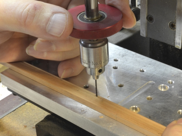
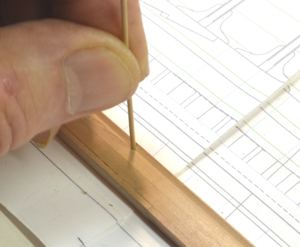
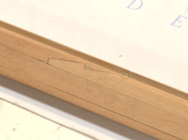
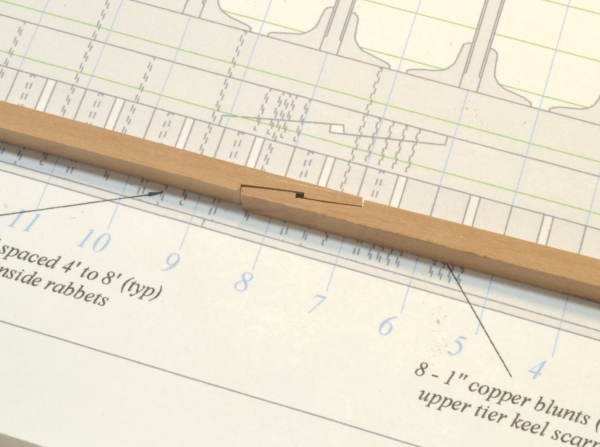
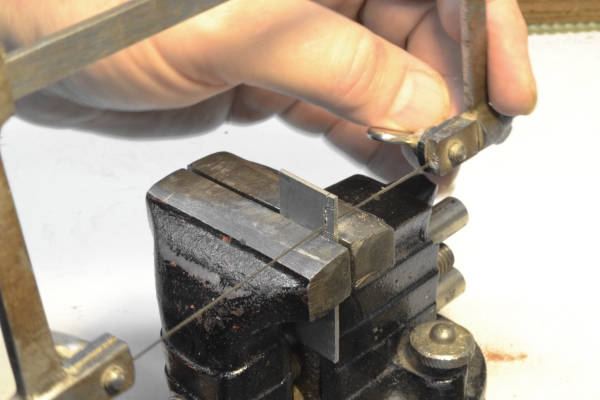
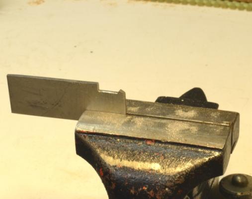
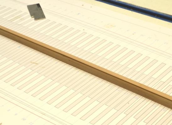
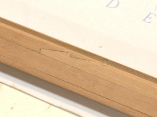
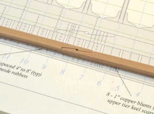
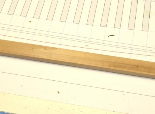
Young America - extreme clipper 1853 Part 6 – Keel Rabbet and Waterstops The keel rabbet provided a seat for the garboard strakes – the strakes of bottom planking next to the keel. These strakes were 9” thick and were bolted through the outside edge into the keel as well as into the frames. The v-notch of the rabbet on these ships was slightly different than the 60 degree triangle of 18C RN ships. It was less sharp and deep. (Note: Having just finished an 18th Century Royal Navy vessel and knowing there is a large following for these types on the forum, I will try to point out differences in structural design that may be of interest. To do this I will use the abbreviation "18C RN" for the earlier types.) To form the rabbet, I used a scraper cut from a piece of stainless plate. I have a lot of these small pieces lying around and they have been useful for this. The first picture shows the scraper being roughed out with a jeweler’s saw. The picture below shows the final filed out shape of the scraper. The cutting edge is left square - but with sharp cutting corners on both faces. The scraper is dimensioned to ride along the bottom of the keel. The cut is finished when the scraper bottoms on the side. Both these rubbing surfaces were rounded over and smoothed to avoid marring the sides and bottom of the keel. The next picture shows one of the first passes on the keel The next picture shows the keel with the finished rabbet. Actually, I did not go all the way to the sharp edge at this stage. I can use this cutter later, after the frames are set to finish the rabbet – when that sharp upper corner is more protected. I may have mentioned earlier, that these ships had no rising wood (or hogg) over the keel. Generally the frames were bolted directly to the keel with long through bolts. Because of this, waterstops were needed to prevent leakage through the joints in the keel into the hull. The rising wood effectively blocked this path in the earlier ships. Although the garboard strakes would be caulked along the rabbet, this did not seal off the keel itself. To eliminate this leakage, holes were bored through the keel at the inside of the rabbet and plugged with long fir dowels, effectively sealing off the top lip of the scarph. I decide to install these. The first picture shows the keel being drilled through the rabbet to accept a three inch waterstop cylinder. The next picture shows a drawn 3" dowel being test fit. These were actually driven in with a touch of wood glue. The excess was then clipped off and the V of the rabbet formed at the ends with a razor blade. The last picture is one of those close-ups that make me cringe, showing a scarph joint, the central wedge and the waterstop under the upper lip. This picture also shows the joint line left using the dark glue. The slightly flat edge, left – for now - at the top of the rabbet can be seen in this picture. The picture also gives a pretty good idea of the finish left by the scraper. The rabbet has not been sanded – nor should it be – to avoid rounding over the corners. These waterstops are a nice little detail. Of course no one will ever see them without having very good eyesight and knowing where to look. they went rather quickly, however, so the cost was small. I guess the next work will be either the stem or the stern post. Ed


- 3,618 replies
-
- 17
-
-
- young america
- clipper
- (and 1 more)
-
Elia, Its always risky business making recommendations - especially when it comes to finishes. I agree that the acrylic finishes have limitations. Painting metal is one of them. These materials were not designed for application to bare metal. Solvent based finishes like enamel and laquer - I include Floquil in this group - are much better in this application. I have used Floquil - brush and airbrush - to paint metal locomotive models and would not wish to consider anything else - unless I had to. I have used acrylic gouache extensively on metal, however - as a paint on tin-lead type miniature figures. These have to be primed first. I use a diluted Rustoleum flat black oil based alkyd enamel for this but have also used a white flat alkyd and flat white shellac - both thinned. The latter has advantages of very fast drying and no oil. The acrylic will adhere to these even in diluted forms - but it is an added step. Also, I will mention that lead can oxidize through finishes to form a white powder, I have never had this problem even on figures painted 40 years ago - a good thing because lead oxide, like lead, is toxic. Also, liquitex is quite a different animal than acrylic gouache. It dries with more gloss and I believe it is softer when dry. I would not recommend it for painting models except for certain effects, where some gloss is needed. There is no doubt that solvent based Floquil is easier to use on metal and its thin opaque finish quality can be hard to beat. I suspect it is running into some health issues. I do not know if this is related to the solvent or to the possible presence of lead in the finish. It might be worth a look at the MSDS sheet for Floquil. My suggestion to try acrylics assumes that the diosol based Floquil is not long for this world. If that is not the case, stick with Floquil where it makes sense. I will. Hope this helps. Ed
-
Thanks, everyone for the comments and interest. I hope you all realize that you are putting pressure on me. Allan, you are quite welcome. I hope reading this won't cut into your golf time. Ed, I wouldn't hold your breath on a kit coming from this. I should be posting Part 6 tomorrow or Monday. Cheers, Ed
- 3,618 replies
-
- 1
-
-
- young america
- clipper
- (and 1 more)
-
Thanks for the comments and the overwhelming reception for the first build pictures. It relief to get stated again after a lot preliminaries. Now I can resume my exercise of running up and down the stairs a dozen times a day between the workbench and the computer. Ed
- 3,618 replies
-
- 1
-
-
- young america
- clipper
- (and 1 more)
-
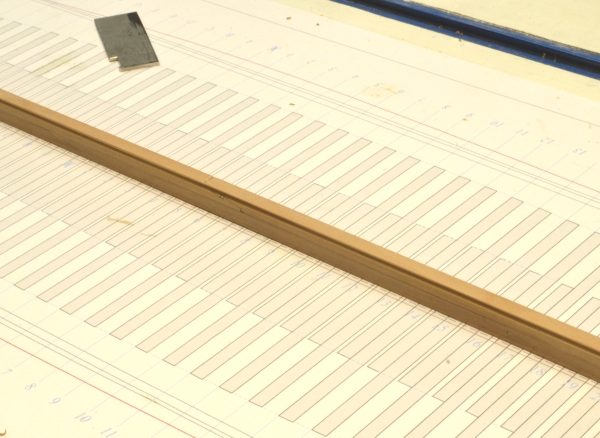
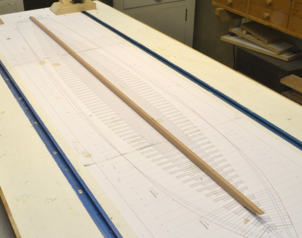
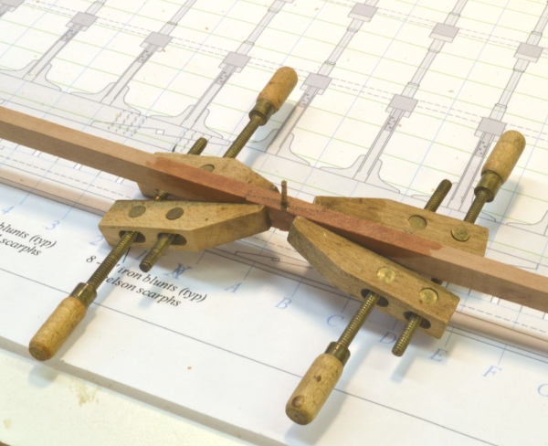
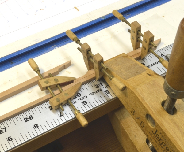
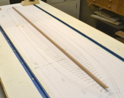
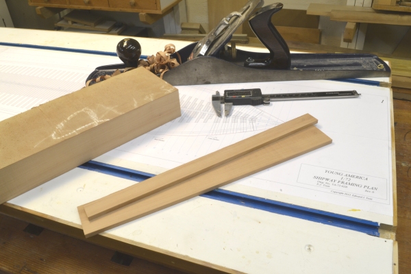
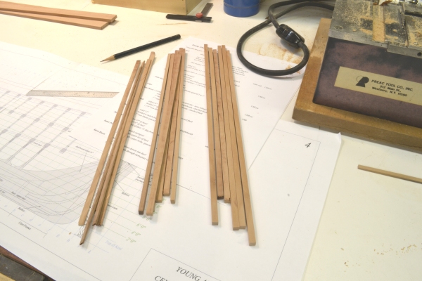
Young America - extreme clipper 1853 Part 5 – Keel Structure So, finally some real work and some pictures. Young America’s keel was sided 16” by 31 inches deep. The main body of the keel was two tiered. The upper tier was 15” deep and the lower was 12” deep. In all of these posts I will use the word “was” rather freely, since original scantlings lists do not exist. “Was” will mean based on the best data and/or reasonable assumptions. In general, I relied heavily on the more complete data for Challenge. I think that extrapolation is a reasonable approach. One builders sidings were not all that different from one ship to the next – unless the first was not successful. Under the two main members is a 4” shoe – a sacrificial protective covering of the main members and boltheads.. This was installed just before launch by removing blocks under the keel slipping it in and fastening it. I will not dwell on my sawmill operations. These were well covered in the opening parts of the Naiad posts. The first picture shows some blanks for the keel members and a piece of the swiss pear material from a few steps upstream in the process. The pear was cut into the piece shown at the top from a roughly 2” thick by 12” wide by x feet long piece. The planks were then cut to rough size on a bandsaw and reduced to final thickness (16”) on a thickness sander. One edge was then planed straight using the small modeling plane at the top – so the final pieces could be accurately ripped to size. The next picture showns all of the pieces needed to make the keel – cut to final width and depth. The members were then cut to final length based on the drawing shown above. Because of the large number of bolts through the actual keel, placement of joints relative to each other, masts, etc., the lengths had to be laid out carefully beforehand to avoid interferences. I did this on the drawing for the model, even though many of the invisible bolts will not be installed. The next picture shows a typical joint of the type used in the top two tiers. The joints are hook scarphs with wedge driven into the center. They are identical except for size to the larger keelson scarph shown on the drawing. That view shows the typical bolting for one of these joints. It also shows one large bolt through the keel for each floor and another longer bolt through the entire keel/keelson centered on the frame timbers aft of the floors. The next picture shows one of the lower tier joints being glued. Darkened Titebond wood glue is used to give a subtle highlighting to the joints. The two parts were clamped with light pressure, the wedge shown was driven through to make the ends butt, and finally the clamps were fully tightend. Excess glue was washed off with clean water – hence the darkened area. With the lower tier fully assembled, the upper tier was added on piece at a time as shown in the next picture. To keep the final two-tier assembly straight, a straightedge and the flat top of the shipway was used to clamp the pieces. Waxed paper was used underneath to prevent gluing to the shipway. The next picture shows some joints in the final three layer structure. The final picture shows the assembled keel lying on the shipway drawing. It is an actual 37” long. Full length keels make for pretty boring photos, but here it is. The next step will be to form the rabbet on either side of the top – at least partially. The top corners of the final rabbets are quite sharp and fragile and will be subject to damage during erection of the frames. However, I want to cut at least some of the rabbet now so water stops can be inserted before framing, but after the bulk of the rabbet has been scraped out. This will be discussed further in the next parts. Ed


- 3,618 replies
-
- 14
-
-
- young america
- clipper
- (and 1 more)
-
Sorry, Brad, I missed that question. Right now I am just hoping to enjoy the leisure of the build and the build log. Any question of a book would be out there in the future. Ed
- 3,618 replies
-
- 2
-
-
- young america
- clipper
- (and 1 more)
-
Thank you, Russ. I will see if I can find any rules that were in effect here in the early 1850's. So far, I have not come across any early documents. Rob, thank you for the pics. I had not seen these or this beautiful model. Where is the model? I have not made any decisions on how much framing to expose or decks to leave out yet and these pictures will help me think about that. Brad, I did see Crothers note on the use of notches by some yards, but I was going by his midsections for Challenge and YA and did look at his midsections for McKay's ships in his book before responding to you yesterday. There is much unknown here, so assumptions have to be made - as you have done. I am using 17" for YA floor depth, just slightly less than Challenge - YA was slighlty smaller. Crothers also used this depth on his plans for YA. I will be making a lot of assumptions on YA's scantlings because no record has survived. There is a good record of Challenge however. I believe - with some support from Crothers - that Comet, Challenge and YA were all pretty similar in timber sizes and were all structurally quite similar - for example, all had the strap iron lattice. The first two were built at virtually the same time and were very successful in terms of structure, so it is logical to assume minimum change for YA. But that is an assumption. Also, at 1:72, some of these variations in scantlings become academic - a half-inch difference is only .007" - a few swipes of 120 grit paper. In looking at the midsections in the book, I did notice that he shows 4 frame joints as opposed to the five I mentioned, however he shows five on his drawings for Challenge and YA. This is a very minor point and a feature that I believe would have been decided at the yard based on timber available. There would be no reson to make two pieces of these toptimbers if one suitable piece was at hand. So, another assumption. Cheers, Ed
- 3,618 replies
-
- 1
-
-
- young america
- clipper
- (and 1 more)
-
Thank you, John. You have raised a very good point. I probably should not have used the word rules. Accepted practices may have been a better term. I think I mentioned only two points. I do not believe marine insurers mandated changing the position of floor timbers from the fore to the aft side of the frame pairs at midship. I believe this was a long standing Royal Navy practice, that offered no structural benefit, and according to Crothers, was not adopted by the American clipper builders. I am not sure that this was practiced other than by the RN - but I really do not know. To follow this practice, an additional standalone frame had to be inserted at midship to allow the switch without having aligned joints on adjacent frames. I believe this is the reason for the departure from normal room and space dimensions around the deaflat on RN ships - at least that is the case in the RN drafts that I have examined. Very awkward. I have not seen this irregularity in non-Navy ( eg East India) drafts. As far as setting the frame joints on diagonals for the purpose of fair joint lines along the hull this appears to me to be another traditional practice - if indeed it was even practiced. I would expect there to be standards relating to offsetting of joints in a frame pair and that would of course have been followed - and is plain good construction. During the period to the mid-1850's there was no governing standard on American merchant vessels - but I believe they invariably recieved normal top Lloyd's classifications. Some were registed in England. The first standards in America appeared in 1857 - the New York Marine Register - known as American Lloyds Universal. In 1867 the American Shipmasters Association promulgated further rules of classification to assist underwriters. The American Lloyds register appeared in 1870. I am not familiar with any of these documents. There apparently were other time-honored English or European practices that were dispensed with by the American builders in favor of equally good, but more efficient methods - at least according to the sources I am using - for example, adding more bolrs and eliminating laboriously cut tables in scarph joints. Young America was a early 19th century mindset as well as a clipper ship. Anyway, I hope that clears up my meaning. Ed
- 3,618 replies
-
- 2
-
-
- young america
- clipper
- (and 1 more)
-
Thank you, Al. I hope you find this interesting. It is a voyage of discovery for me, too. Rob, what's nice about all this is that everyone can pursue it in their own way. Ed
- 3,618 replies
-
- 1
-
-
- young america
- clipper
- (and 1 more)
-
Brad, I could be wrong, but I do not believe the plans for Champion were by Crothers. The list of his plans for clippers that I have include: Challenge, Lightning, Black Hawk, Comet, Young America, Red Jacket. There are also another dozen or so non-clipper Sea Gull Plans. The plans I have of Crothers (Lightning, Challenge, YA) are excellent. Yes, I do intend to reduce the sidings of the futtocks as they progress up. I would make the following comments on your rendering: 1) I do not believe that these ships (McKay or Webb) had a rising wood, or hogg, (like 18thC RN), on top of the keel, so there should be no notch at the bottom of the frame pair. The frame bolted directly to the keel. I believe the thickness of the floor over the keel on Challenge was 17 1/2". I would be interested if you had information to the contrary on this point. 2)The frame joints closest to the keel are the floor heads - the ends of the continuous horizontal piece whose center lies on the keel. In your picture it is behind the forward piece, whose joints are the next pair going upwards. These pieces are the lower (or first) futtocks. They are not one piece but join at the centerline atop the keel. 3) I believe there should be at least one more joint, in the timber above the lower futtock and perhaps another above the second futtock head on the back frame. I have placed five joints in the full frames at the diagonal lines shown in the body plan above. I gather, from what I have read, that American builders did not necessarily follow the rigid rules used by earlier, example 18thC RN, ships. They may have simply placed the joints in the frames to suit the timber availoable, keeping a minimum distance between joints, of course. So, my last point is speculation on my part. Locating joints on fair diagonal lines will make for a neater model and in the absence of hard data, that is the direction I am taking. 4) At your scale, you may wish to include the limber notches on either side of the keel on the undersides of the frames. These allowed entering water to flow to the pumps. You will see these on Crother's midsection for Challenge. Also, it was common in earlier RN ships to reverse the position of the floors from the fore to the aft side of the frame pair at midship. The American clipper builders placed them all on the same side - and may not have been particular about which. The frame with the floor will be the higher frame - as you have shown - going up the the fancy/monkey rail. The other frame in the pair stops at the planksheer. Let me suggest and encourage that you install bolts in your model. In a cross section this would add interest. Crothers is very thorough on bolts - size, type and placement. Assuming I am correct, I hope this helps and doesn't cause rework. If it does, let me know and I will repost the picture of my Naiad rejected parts bin to make you feel better. Rob, thank you. This is my first clipper. Ed
- 3,618 replies
-
- 4
-
-
- young america
- clipper
- (and 1 more)
-
Thank you, Brad and those who "liked" the last post. I have started construction and should be posting some progress pictures soon. Brad, good luck with your Challenge - a most amazing ship. You are right about Crothers book. It has been invaluable - along with several others. I assume the Smithsonian plans you mention were Chapelle's? They may be the ones that are printed - small size - in his The Search for Speed Under Sail - an excellent book. Crothers also published very detailed plans for Challenge - two large sheets 1:96 under the name SeaGull Plans, now available from Taubman/Loyalhanna. There is also a very thorough description - written by the reporter Duncan Maclean - reprinted in American Clipper Ships, Vol I by Howe and Matthews. You may already be aware of these but I thought I would mention them. Ed
- 3,618 replies
-
- 2
-
-
- young america
- clipper
- (and 1 more)
-
HMS VICTORY 1759 by isalbert
EdT replied to isalbert's topic in - Build logs for subjects built 1751 - 1800
Beautiful work, Isalbert. Ed -
Well, John. I am glad to hear that neither of us is crazy. Cheers, Ed
-
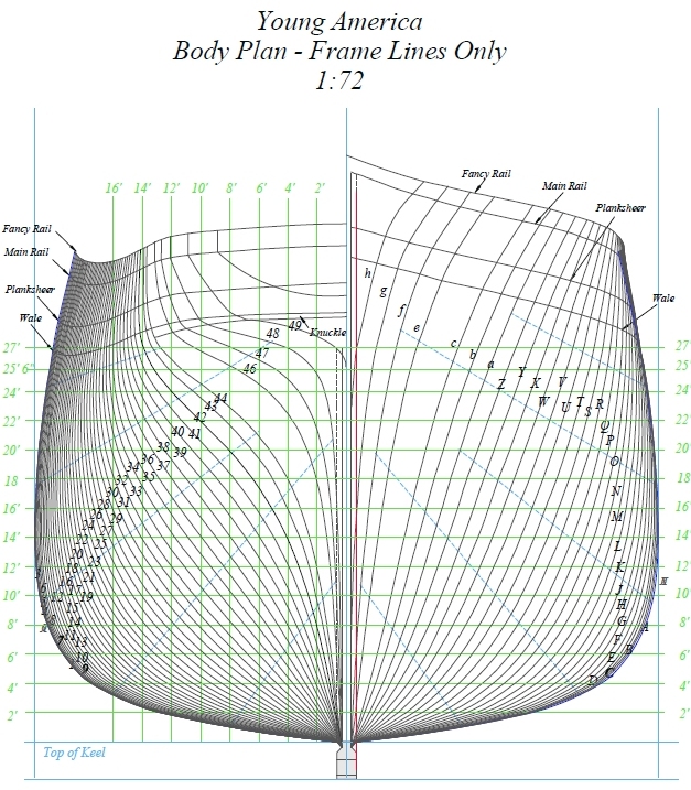
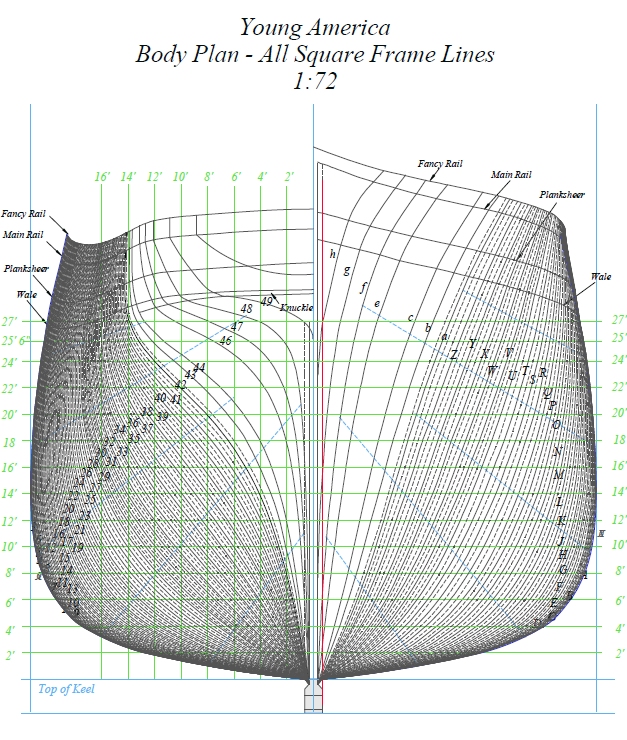
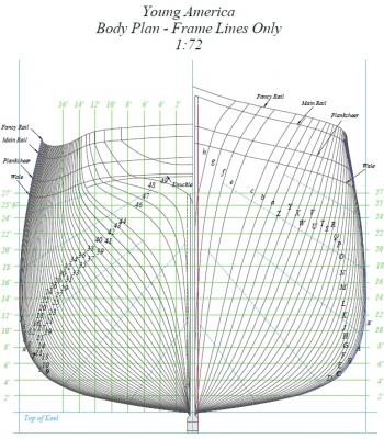
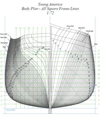
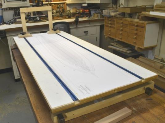
Young America - extreme clipper 1853 Part 4 - Webb’s Young America Well, they say that every good plan eventually degenerates into hard work. The research and planning for the model has been fun, but now it is time to get down to business. That does not necessarily mean getting right into the workshop, although apart from the frame process tests discussed in Part 3, I do hope to start forming the keel in a week or two. Right now there is a ton of frame lofting to do and sometimes that can get tedious. With 80 frame pairs, totaling 160 frames, there are a lot of patterns to create. Please be patient. In Part 3 I had intended to discuss Young America, and my choice of her as a subject, but I inserted the framing process work instead. So, I will discuss YA here while I take a break from lofting frames. Webb William H. Webb was widely regarded as the premier American shipbuilder of the mid-19th century period. His father Isaac Webb took over the New York shipyard of Henry Eckford in 1825 and operated it under the name of Webb and Allen until his death in 1840. During that time, 23 ships – from cutters to packets were built. In 1840 William Webb took over the yard. Over the next 30 years, 135 ships were built – packets, clippers, steamers, barks, ironclads, and of course, extreme clippers – 9 of them. Following Celestial and Gazelle, the third.of these was Challenge, launched in 1851. The purchasers single requirement was that Challenge should be the finest and fastest merchant ship in the world, regardless of cost. At 252’ feet she was the largest extreme clipper to be launched to that date. Comet at 241’ was launched two months later. There were four more before Young America in 1853 – the ship that Webb considered his masterpiece. He knew the extreme clipper era was ending and that YA was the last he would build. He went on to build many more ships through 1869. In later life Webb turned to philanthropy, starting a school of marine architecture for boys of limited means. To this day, tuition at Webb Institute is free to qualifying applicants. Young America Young America was named after a broad, popular cultural-political movement that flourished in pre Civil War America. The movement advocated democratic reform, free trade, expansion and similar themes. It was a largely urban, middle class movement that became associated with the Democratic party and Stephen Douglas. It paralleled similar movements in Europe. Some design particulars: ~243’ long od, 43’2” extreme breadth, ~26’ depth of hold 1961 tons – old measure 20” floor deadrise (9 deg) deadflat forward of midpoint 25’ swell of the sides (tumblehome) 20” 3 decks circular stern cost $140,000 Excuse the approximate numbers on her size. There seems to be a variety of measurements reported and due to lack of standardization, it is not always clear what they are. Fortunately the original offsets (see below) ensures that the model will be correct. Other features will be described and compared to other similar ships as they occur later in construction. I include deadrise in this list because it was considered a key variable in improving speed. Of course as the angle of the floors increased, hold capacity decreased, so the pronounced deadrise of up to 20+ degrees that was employed on the early extreme clippers clearly emphasized speed over capacity in these ships. As the period advanced, bottom shapes became more flat, without an attendant loss of speed. At 9 degrees YA is a good example of the evolved design. The key structural issue in these ships was the prevention of hogging – the downward deformation of the hull at the ends – sometimes to the point of failure. The problem occurred in wooden ships because of reduced buoyancy at the ends due to less hull volume at the bow and stern. The long length and the sharp entry and run aft in these ships severely aggravated the problem. The obvious solution was to increase hull strength by various means – huge keelsons, heavy inboard planking (called bilge keelsons), various forms of triangular bracing, anti-hogging chocks, diagonal iron lattice-work bolted to the frames, kneed pillars, and generally heavy construction - to the point of reducing hold capacity. Relative to the competition, Webb employed these features with a lighter touch, generally keeping scantlings smaller. He also employed some innovation in going to variable frame spacing with frames spaced further apart toward the ends of the hull where the smaller sections required less structure. This is said to have reduced the dead weight of the structure at each end by up to 25 tons – a substantial relief of the hogging strain effect. The long life of Young America (and others) is a testament to this good engineering. Availability of data on Webb’s ships is limited to books of plans from his papers for some of his ships. Data for Challenge is fairly complete, since at her launch detailed descriptions were printed. For Young America, less original data is available. Building a fully framed Young America would not be possible for me without the work of William L. Crothers, specifically his recently published (1997) The American Clipper Ship, Characteristics, Construction, Details. The book is a thoroughly researched tour de force on clipper ship construction. In it he has reproduced Webb’s original table of offsets for both Young America and Comet – essential for producing hull drawings. He has also included substantial basic scantling information for a variety of ships. Based on the assumption that Challenge, Comet and YA would all be similar in structural design, I believe an accurate framed model design can be made forYoung America. Having reached this conclusion, I made my choice to proceed. Crothers also published model plans for a number of ships under the name Sea Gull Plans. The plans for YA (1:96) do not include framing or structure, but will be useful for deck arrangements and rigging. I have also used his similar plans for Challenge and McKay’s Lightning for reference. I have acquired and studied a variety of other sources, but in the main, Crothers has nicely collected most of the useful data – and has usefully referenced his sources in detail. Below is an image of the CAD body plan from Webb’s original table of offsets. This provides a good description of the hull shape. It is very different from my previous model of Naiad and ships of her type. The method of creating the body plan was also much different. Gone are the heights and breadths of rising, the circular sweeps and points plotted on diagonals. It is possible that a half hull model was made first and the waterline/butt line offsets taken from that to loft the ship. This was a common practice. This body plan is a starting point for the frame lofting. It shows only profiles at primary station lines. To this drawing I have added all of the intermediate frame profiles as well as profiles between these to permit beveled frame patterns to be lofted. The intermediate profiles were plotted from points measured on a half breadth plan constructed from the original table. That body plan is shown below. The cant frame profiles are not shown in this plan. The square frame lines are extremely close together, especially near midship. Fortunately, only the computer has to see them. The diagonals on this plan were added only to set the height of the frame joints in fair lines. I do not believe the American builders paid too much attention to this, but it will make a neater model. In addition, a table of scantlings is being progressively constructed from various sources. As proof that there will really be a model starting soon, I have included the following photo of the old Naiad building board sporting the framing plan for YA. The shipway is just long enough. Ed
- 3,618 replies
-
- 18
-
-
- young america
- clipper
- (and 1 more)
-
John, apology accepted. I don't want to debate the humor in your use of the word "evil", but I am happy to discuss acrylic finishes. If by "reconstitute" you mean that the finish is affected by wetting after it has dried, with acrylic finishes this is simply not the case. Perhaps you are referring to non-acrylic gouache, which like watercolor, has a water soluble binder. The acrylic copolymers used in both acrylic artists colors and acrylic gouache, including Jo Sonja's, form a waterproof polymer matrix that cannot be redissolved with water after drying. I do not want to give the impression that these finishes are ideal, only that they are an option - one that I have found effective. Others can try it for themselves. All finishes, in my experience have pluses and minuses, but I am quite certain from experience and on a technical basis, that the rewetting problem you describe does not exist with acrylics and should not put off people from trying these products. Ed
-
Danny, I never thought of the simple solution of blowing through a tube. Bravo! Toni, if you are building your model on the kitchen table, then you deserve even more praise for the quality of your work. I seem to need an entire workshop and that is often not enough. Also, I can't bear the thought of cleaning everything up before dinner. Well done. Of course, permanent residence of the model in the workshop with all the other activity - sawing, thickness sanding, etc - even with dust collection - adds to the cleaning requirements. Ed
-
John, I have never experienced either of the problems you cite and can think of no technical reason for them. Sorry to disagree. I usually preface everything I say about finishes with the caveat that there is much that is personal in these choices and this is of course the case with acrylic gouache. By the way, I don't think I've earned the adjective "evil" and would appreciate your dropping it. Thanks. Ed
-
Rob, Thank you. Your comments are appreciated. You are right. Preferences vary. I will say that deck arrangements and details were not among my decision variables. Neither was size - although YA was a pretty large ship as extreme clippers go. I was looking primarily at the form, structure and performance of the extreme clipper type. Webb built 9 of these, McKay 11 - at least by the classification given by most experts. Of McKay's ships I considered Lightning and Sovereign of the Seas - of Webb's Comet and YA. Ultimately, I wanted something after 1851 when the early infatuation with high floor deadrise was beginning to wear off and the designs became more moderate in that regard - without really sacrificing speed. The 335 foot, four masted Great Republic is really a different class of ship and the fact that she never sailed as originally built leaves her a bit of a mystery. Donald McKay - the ship - was classed a clipper packet, so is not indicative of the type I was interested in. If you have followed my previous build, you will know that wooden ship structure is my major focus. What I found interesting about Webb was his judicious use of timber. His designs were light, but very strong - as YA's sailing life can attest. I will discuss some of this in the next part. Ed
- 3,618 replies
-
- 3
-
-
- young america
- clipper
- (and 1 more)