EdT
-
Posts
2,214 -
Joined
-
Last visited
Content Type
Profiles
Forums
Gallery
Events
Everything posted by EdT
-
Frank, Keep in mind the difference between the normal Artists Acrylics and the matte gouache. YOu might want to try a tube or two first. I normally thin them a bit to improve flow. They are thick from the tube. Ed
-
I finally found a link to my usual supplier: http://www.jerrysartarama.com/discount-art-supplies/acrylic-paints-and-mediums/chroma-acrylics-and-mediums/jo-sonjas-artists-colours.htm Ed
-
Let me put in a plug for matte artist's acrylics - called acrylic designers gouache. I started using these in 1971 when they first came out (Rowney UK) to paint miniature military figures. The finish is dead matte. The colors today are as true as then. They are highly pigmented, waterproof when dry, non-yellowing, can be water diluted to any consistency from opaque coat to semi transparent washes/stains, or mixed with acrylic mediums to give increased gloss,. The color selection is enormous and they are much cheaper ( and in my opinion better) than hobby paints, which are made from the same acrylic emulsions. In the late seventies these seemed to go out of production but have come back. I have painted over 5000 figures using these materials. I used them diluted to dye the rigging rope for Victory and to stain wood. Very versatile. I have used Floquil, SCalecoat, Humbrol enamel and acrylics, Testor's, Vallejo and most others. Here is a link to the type of acrylic gouache (Jo Sonja) that I have used for the last few decades. ( I have not bought from this particular supplier.) http://painting-crafts.com/jo-sonja-tube-colors-2-5-oz.html Other brands are undoudtedly just as good - eg. Turner Acryl Gouache - just make sure the finish is matte - look for the word gouache. Do not confuse these with the much more prolific Artists Acrylics - these have a semi-gloss or even gloss finish and do not seem to dry as hard. I have used them where some gloss is desired. Ed
-
Toni, I gave up on all attempts to keep the dust and debris out - masking tape, foil, etc. I used a dry, long handled, stiff bristled, artists round to loosen dust where it could be reached, then blew it out with the shop vac in reverse mode. You can direct the air through the lower frames from the outside in the final step. I did this periodically throughout the work. I also tried using the pressurized cans for cleaning electronics, but found that not to be necessary. If you use an air compressor, make sure it is either an oil free type, or that the oil trap is clean. Sometimes a good shake with the model inverted is also needed to dislodge larger bits or to recover parts. Good luck. Ed
-
Thanks, everyone. Hakan, nice to hear from you again. I am so glad you got the point on the holes. It is the whole key to frame pair alignment and pre-erection bevelling. The precision of CAD makes it possible, but the holes have to be positioned on CAD overlays during lofting. I used a different method for aligning the frame pairs on Naiad so they could be pre-assembled, but on Naiad there were air gaps between paired frames and also the chocks to deal with. That may make this approach more difficult, but I believe still do-able. Having the original patterns on both faces of a frame pair after assembly is very useful. On McKay - thats where I was headed, but found Webb ships a lot more interesting. I think McKay was more media savvy and has somehow come out on top of history's popularity contest. Interestingly three of the most notable clipper designers - Webb, McKay and Griffiths - all apprenticed together under Isaac Webb, Williams father. On the scale issue. Bigger would be great, even though bigger isn't always better. Of course at 1:48 the fully rigged model would need a case at least 7 feet long, 5 feet high, and 2+ feet wide. 1:72 is not exactly small at about 5'9"l X 3'6"h X 1'6"w. YA sported a main yard 100 feet in length - before stuns'l booms. I don't think I'm headed toward 1:96 again anytime soon. Victory with 104 guns to turn, mount on carriages, etc. was quite enough - to say nothing of the dozens of 1/16" blocks and those pesky port lid hinges. Thanks again, everyone. Ed
- 3,618 replies
-
- 3
-

-
- young america
- clipper
- (and 1 more)
-
Egen, I do not have a definitive answer to your question on the pump, however, I will say that the only place I have seen the mechanism of the type in your scan is in the Pandora book. Goodwin, Lavery and White (in Diana) show the simpler type. I find it interesting that pumps are not specified in the ship's contracts of the period. I assume from this that the Navy supplied and probably installed them in fitting out after launch. I drew the same conclusion with reference to the stove - also omitted from the contracts. This also suggests to me that some of these items may have been recycled from other decommissioned ships. Like you, I would be interested in more definitive information, if anyone has it. Ed
-
Toni, keep an eye on the Seawatch website. I believe Bob Friedman intends to have at least a sample with him at the conference. However, these things are always subject to blips in the publishing process. I am certainly hoping it will be available before then. Ed
-
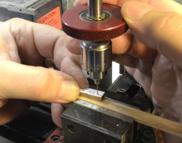
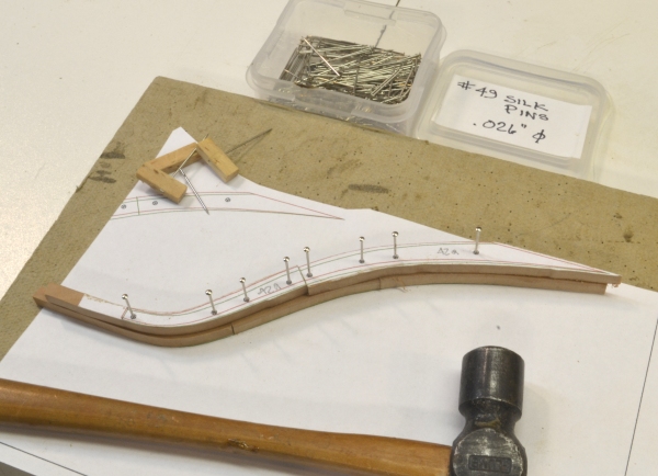
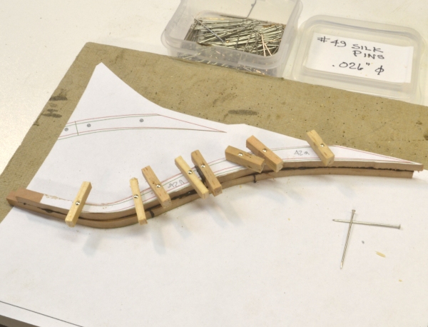
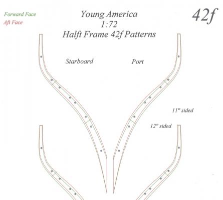
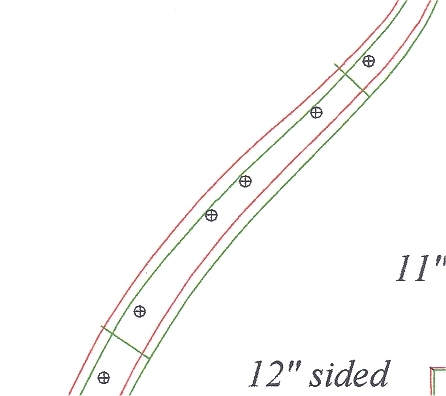
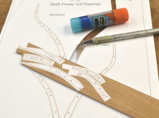
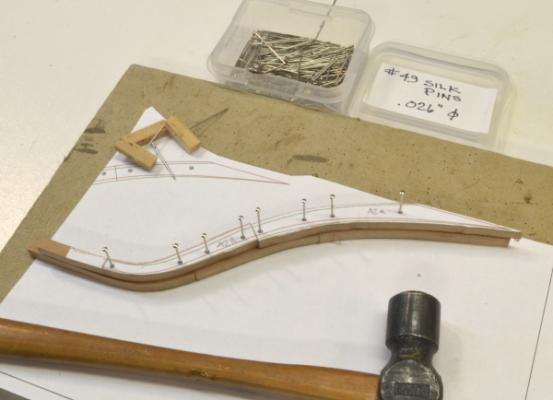
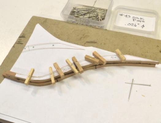
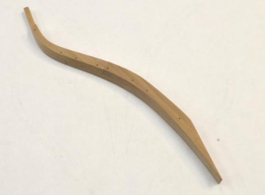
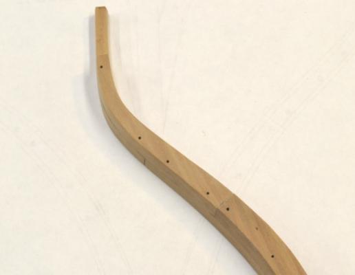
Young America - extreme clipper 1853 Part 3 – Scale vs. Framing Instead of continuing with the historical narrative at this point as planned, I thought this would be a good place to insert some modeling content to break up the text that might be tedious to some. Also, at this stage I am faced with two issues. First, I need to resolve the question of scale. Second, I need to begin lofting frames. Since I am a strong believer that drawings exist to support the specific building process, I wanted to nail that process down before getting very far into creating patterns. These two issues are closely related. The question of scale I have already decided that 1:72 is probably the largest scale for a rigged model of a ship this large that my workshop (or house) can comfortably support. The question is whether an accurate fully framed model is feasible at this small scale. I was concerned about this at 1:60 for Naiad, but that worked out very well, so I am encouraged about moving to 1:72. To confirm this before investing too much time I decided to loft and make some test frames. American Clipper Framing Some description of the framing of American clippers is required at this point. It differs from the 18th century Royal Navy model that many are familiar with. First, every frame was paired. There were no standalone frames as was the case my previous Naiad model. Also, there were no air gaps between the paired sections and no chocks at the joints. Every frame pair was bolted together on the frame or station line with offset futtock joints. There were relatively few cant frames, but a large number of “half-frames”. These were square to the keel but bolted to the sides of the keelson/deadwood – like cant frames. These started at the fore and aft ends of the square framed midship area. The starting point was begun when compass timber to shape the increasingly V-shaped floors ran out. The cant frames began when the bevels of the half frames no longer permitted bolts holding the pairs together to be driven “normal” – that is, square – to the faces of the frames without breaking out into either the inboard or outboard faces. Young America had a total of 80 frame pairs vs 60 for Naiad. Framing Process After some work on the parts of a test frame, I quickly concluded that the 1:72 scale was feasible – a great relief – so I will not dwell on that. However, the development and testing of the fabrication process may be more interesting. Following is a brief overview. Frame assembly can go faster without having to fit several chocks to each frame. To eliminate the potential bottleneck of one assembly jig, the new process eliminates it. Sections of the frame pair are aligned for assembly using predrilled pin holes on centers precisely placed on both the fore and aft patterns during the CAD lofting process. The new process also provides for patterns to be left on the fore and aft faces of the assembled pair. Since these patterns show the profiles for the fore and aft faces, the frames can be pretty well beveled inside and out before erection on the keel, eliminating a lot of post-framing fairing – especially difficult on the inside of a narrow hull with sharp entry and run aft. To make this beveling accurate and to speed the assembly process, all the futtocks will be sided to the same size as the floors. The reduced sidings of the upper futtocks will be milled off later, after beveling. The first image shows part of the pattern sheet for the forward section of half-frame 42. This is the last half frame aft and the most highly beveled so it is a good test case. The next image shows a close up of one of the futtocks on the pattern. Note the placement of the bolt/pin hole centers. These were placed with CAD objects of the two frames of the pair overlapped so the holes could be located in an aligned position on each frame. Note that on this most beveled frame the hole circles on this aft frame face are right against the smaller forward (green) profile. They are equally close to the outer edge of the forward face. Frames aft of this will have to be canted. The circles are larger than the bolt size. The diameter includes an allowance for some clearance between the bolt and the profile edge. The next picture shows the patterns pasted on to a piece of pear ready for cutting out. Here I discovered that to have patterns left on the exposed faces, I had to use patterns from the other half of the frame. It was also clear at this point that every piece needed to be labeled and that the Starboard and Port labels on the pattern needed to be clarified - some lessons for the final lofted pattern content. The next picture shows an alignment/bolt hole being drilled. This is the most error-prone and critical part of the process. The holes need to be accurately located and square to the frame. The next picture shows the beginning of frame assembly. The frame segments are aligned by the pins and temporarily pinned to a copy of the pattern for a check. The segments are then glued together as shown below. Considerable excess length was left at the top to support the frame during milling of the reduced sidings of the top members. Because of frame curvature this approach did not work out so the sidings will have to be milled using spacers under the reduced parts of the milled face. The pins with softwood blocks are hammered down into the fiberboard and act as clamps. The completed - assembled and fully bevelled - port half frame 42 is shown below. The sidings of the upper futtocks have been reduced. The aft face is up. Note that the toptimber on the forward frame is higher. It goes up the the fancy rail on every frame pair. The aft frame goes only to the planksheer – the height of the open deck. The closer view below shows the bolt holes – a safe distance from the inside edge. They are a similar distance from the outside edge on the opposite face. For this test I took the beveling almost to completion in this test frame – right to the green lines on the forward face and to the red lines on the aft face. . There is obviously no need to do that. Leaving a slight amount for the final fairing may be safe bet. I hope this explanation has not been too confusing. Thinking about this or explaining it sometimes leaves me dizzy. At this stage, I concluded that the process, with some minor tweaking, is feasible and efficient, so I will proceed with the lofting on this basis. A milestone. Ed

- 3,618 replies
-
- 21
-
-
- young america
- clipper
- (and 1 more)
-
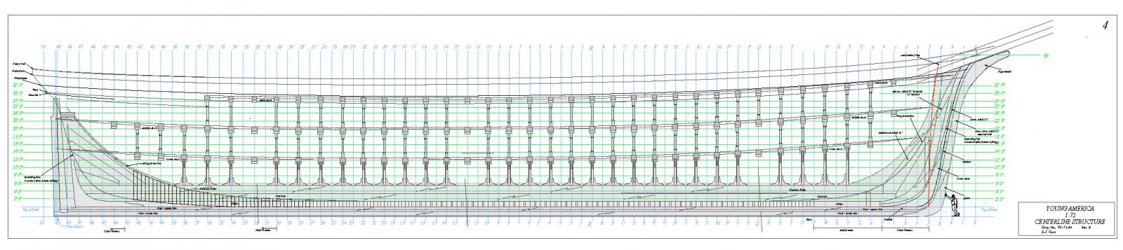
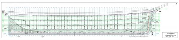
Young America - extreme clipper 1853 Part 2 – Some Very Brief Background The Extreme Clipper Era The term clipper had been applied to fast sailing ships since the 18th century. The “clipper ship” was the larger full-rigged type that began to appear around 1840. The term “extreme” referred to a class of these ships that were designed with one overriding objective – speed. Carrying capacity, the traditional priority in the design of merchant ships, was virtually ignored in the “extreme” clipper designs. At the risk of over-simplification, demand for ships of this type arose from some fundamental market forces that emerged in the 1840’s. The end of the East India Company monopoly in 1834 and later developments in the opening of trade with China, allowed a mass market for tea to grow in Britain. Demand for tea - and especially fresh leaves – became insatiable, driving prices skyward in the face of short supply. In America, the discovery of gold in California created an immense demand for food and supplies as the small subsistence village at San Francisco struggled to support sudden and huge population growth. A similar situation arose in Australia. High prices made fast fulfillment of demand the key to spectacular profits for merchants in London and New York, respectively. By 1850, shippers were demanding the fastest ships - without delay and without concern for capacity or cost. In addition, they demanded – and got – continuous hard-driving from their captains. Earnings from one or two voyages – a year’s sailing - were often enough to return the cost of a ship. Voyage times to or from China that typically took the leisurely East Indiamen 18 to 24 months dropped into the range of 3 months. A lot of people got very rich. It all ended when the Suez Canal opened in 1869. Steamships were then able to take a slice of the British eastern trade, creating a glut of fast-sailing clipper tonnage globally and ending the production of the extreme clippers. The Extreme Clipper Design for speed meant long sleek hulls with sharp entry at the bow and sharp run aft at the stern. Early versions emphasized more deadrise – less flatness across the floors – but this was moderated in the later years. The ships carried a huge spread of canvas. Very importantly, they had to be able to withstand continuous very hard driving in regular voyages that included the violent extreme southern latitudes. The long lengths of the ships (up to 240’ and more) and the reduced buoyancy at the ends due to the sharpness of the entry and run, introduced major hogging issues. All these factors put a new level of demand on the internal structures. The American built clippers were essentially all wood. Seemingly inexhaustible timber resources and limited iron-making capacity prolonged the wooden ship era on this side of the Atlantic as the British increasingly adopted iron and composite structures. Part of the reason for Young America as a subject was to explore this last phase of wooden sailing ship development. Some aspects of the structures of these ships can be seen in the much reduced jpg image below – one of the first group of drawings for the Young America Model. This drawing shows the centerline structure of the ship. There are a few things to note. First, the ship is quite long – about 240 feet. Typical of these ships, the height at the bow is quite a bit higher than the stern in a departure from earlier types. The keel/keelson structure is massive to help resist the hogging strains on the ends. In fact the keelson has become the main longitudinal member taking over that role from the keel. The keelson is 4 feet deep and consists of two levels of timber – called tiers. In another departure from earlier ships it also runs in a straight line from stem to stern – causing some interesting problems that will be discussed later. The keel itself is 31 inches deep and also in two tiers plus a shoe. These were by no means the largest keel and keelson structures employed. Webb was fairly sparing of timber. Some of McKay’s structures were much more substantial. Note also the regularity in the spacing of the deck beams and the heavily kneed pillars under every beam. Finally note the extremely small overhang at the stern counter – just enough to accommodate the helm directly over the rudder. This reduced the impact of following seas on the low stern – a problem of long standing. A number of other interesting structural features were also employed. They will appear on other drawings and will be described later. In the next posts I will further discuss Young America herself. Cheers, Ed
- 3,618 replies
-
- 10
-
-
- young america
- clipper
- (and 1 more)
-
Thanks, John. Volume II should be out within a month. Ed
-
Thank you all for your interest and support for the new project and the subject. Greg, the model will be fully-framed much like the format of Naiad - bolts, knees, ironwork, one side exposed, etc. I am not aware of any fully-framed clipper models, but it would be hard to believe they do not exist. Perhaps someone knows of one or some? A very important enabler for this project is William Crouthers book The American Built Clipper Ship, Characteristics, Construction, Details. While this is by no means Steel's Naval Architecture, I believe it and other sources may be sufficient to piece together a very authentic framed model. Crouthers work is new (1997) and, I believe unique, in its thoroughness as a survey of these ships' construction. There is no single repository of source material and there are many gaps, but the research that went into this book was prodigious. I could not have begun to do this level of research of primary sources. I will discuss all this in the early parts of the build log. There are some very interesting structural aspects - and unresolved questions - in the construction of these ships. I get more enthused about the project by the day. Ed
-
You are really rolling here, Jerry. I like the trusses and enjoyed the rudder video. although I am a little seasick. Cheers, Ed
- 553 replies
-
- 1
-
-
- sloop of war
- constellation
- (and 3 more)
-
Thank you, Chuck.
-
Thanks for the comments and interest. After years of trying to understand Royal Navy ships, this will be a departure. It is taking some time to get off the ground. CMG, I have seen the pictures of the model you referenced. Thanks. John, I have not yet decided if the model will be rigged and have not considered the topsail configuration. I would probably go with the original singles. Piet, I have read a small bit on Nightingale - a very interesting history - built in New Hampshire. She was much smaller than YA and would make a great model. Ed
-
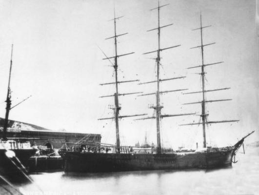
Young America - extreme clipper 1853 Part 1 - Decisions I took most of the summer deciding whether I would undertake another ship model and if so, what the scope and subject would be. I had a lot of time to think about this while catching up on neglected home maintenance and repair projects. After deciding that I needed the challenge of another ambitious project, the decisions on scope and subject kept me busy through July. I also had to decide whether I could commit to another Naiad-like build log. We shall see. I received a number of suggestions on subjects and that input is most appreciated. Since I expect this project to span a number of years, the decision was a big one. I have enjoyed wrestling through the process of deciding. I had a number of criteria: 1) significant design/drafting content, 2) fully-framed construction to further explore my interest in structures, 3) a change from the well-trod path of fully-framed 18th Century Royal Navy subjects, 4) avoiding commonly modeled ships, and 5), I thought it was time to do an American ship. Before focusing on the extreme American clippers, I considered, among many other possibilities, a 19th Century American warship, perhaps steam-sail, and looked seriously at some of the ships by John Lenthall, built locally at the Philadelphia Navy Yard – examples: Germantown (sail), Princeton (screw/sail), Susquehanna (paddle/sail). In the end, the idea of the extreme clipper was too attractive to dismiss. To me, this type represents an apex of achievement in wooden sailing ship design and construction – in terms of sleek hull lines, sailing performance, structural development and sheer beauty. In the design of the extreme clippers, minimum tradeoffs were made to the one paramount design parameter - achieving the shortest sailing times between far-flung ports. Speed meant not only sleek hull lines and a spread of canvas, but also the strength to withstand continuous hard driving, day-in, day-out. After deciding on the clipper – and an American (meaning all wood) clipper - I chose the work of William H. Webb of New York. It would have been easier to select something from his more popular competitor, Donald McKay, but McKay’s ships built at East Boston, have long been widely modeled – Staghound, Flying Cloud, Lightning and others. McKay’s papers do include substantial structural detail – very tempting. Webb, too, has left papers, and these have been explored, with information published in the secondary sources I have used. There are many gaps, but there is a family resemblance in details to all these ships and many practices and scantlings were commonly adopted. Webb presented more of a challenge – in more ways than one – as I will describe later. Of Webb’s ships, I chose Young America, built in 1853, his last extreme clipper. Less is known about her construction than some of his others, so the task of piecing her structure together is more interesting. I will discuss this, the ship, and the extreme clipper era in the next posts. Below is a photo of Young America, docked at San Francisco, a frequent port of call for her. She was built mainly for the East Coast to California trade. In the picture she is rigged with double topsails - a modification from her original single topsail rig. There are also some paintings of her. She was considered Webb’s masterpiece – one of his twelve clippers in a list that included renowned ships like Challenge, Comet, Invincible, Flying Dutchman – all of these examples being 200 to 240 feet in length. YA enjoyed a thirty-year career that included fifty passages around Cape Horn. She set a number of sailing records and earned a ton of money for her various owners – and for those who made money betting on passage times. In 1883 she left Philadelphia carrying 9200 barrels of Pennsylvania case oil, cleared Delaware Bay and was never heard from again. The model may be fully rigged. I will decide later. With the hull length involved (240’) the scale is likely to be 1:72, but that is not yet cast in stone. Structural drawings are well along and I expect to start construction later in September. I hope these posts will be of interest and perhaps draw some attention to this somewhat neglected modeling genre. Ed
- 3,618 replies
-
- 28
-
-
- young america
- clipper
- (and 1 more)
-
HMS Naiad 1797 by albert - FINISHED - 1/48
EdT replied to albert's topic in - Build logs for subjects built 1751 - 1800
Right you are, Druxey. From what I see so far, I am sure Albert is up to the task. Ed -
Beautiful work, Toni. Love the lanterns. Ed
-
HMS Naiad 1797 by albert - FINISHED - 1/48
EdT replied to albert's topic in - Build logs for subjects built 1751 - 1800
Congratulations on a great start, Albert. Good luck with the project. Ed -
Thanks, Jerry. Somehow I missed that. Ed
-
Very nice coppering job, Jerry. The eraser is a good way to clean up the work and I used it some years ago on Victory's 3700 plates - doesn't leave anything behind like steel wool threads or skin. I assume the copper is self-adhesive. Do you know the thickness? Can you recommend a source? Thanks, Ed
- 553 replies
-
- 1
-
-
- sloop of war
- constellation
- (and 3 more)
-
and thank you, Brian.
-
Thank you, Peter, for this sensible suggestion. Ed
-
Sorry to have broken the rules and, of course, will comply. Deletion on sight seems a bit heavy handed. Seems like a gentle reminder would be quite effective. No one is trying to turn this into a multi-lingual site, least of all me. Just trying to be courteous and return greetings to some whose English is not up to our level, but are still interested in the content or who may need help. Sorry, Ed
-
I have recently become a convert to TurboCAD and find it to be extremely well suited to drafting model plans. I was forced to change because the product I used for Naiad, Visio Technical 4.1, is long extinct. TurboCAD is also a much more capable program. As with any complex software, there is a learning curve and I spent about a month this summer getting familiar with the product. The abbreviated User Guide that comes with the TurboCAD Deluxe product is relatively useless but a full 700+ page pdf version can be found online. I have printed out the 2D portions of that and find it a very useful reference. The product is "deep" and it is worth taking time to learn the features and settings. It took me about a week to figure out how to print a 1-pixel line. Among the many features, I find the dimension measurement functions very useful in lofting. The paper space features for creating print views at whatever scale are also an excellent feature. I can recommend it highly. I am using an older Version - TC 17 - that can be had from Amazon for about $30. Ed
-
Grazie, Lino. Abito in Bucks County, in Pennsylvania orientale. Ed