EdT
-
Posts
2,214 -
Joined
-
Last visited
Content Type
Profiles
Forums
Gallery
Events
Everything posted by EdT
-
Thank you for the translation, Lino. My own translation was close to it. I do not know if I will ever get to Ascoli. My grandfather left there in 1900. It is a long time. I am happy to hear you will build Naiad. I hope you will be able to translate the book. Volume II should be out very soon. Ciao, Ed
-
Thank you, Jim. I am still pondering what might be next. I am glad the liver of sulfur is working for you, Frank. Ed
-
Frank, Thanks for your comments and interest in the posts. I have become a true believer in liver of sulfur on copper to make model parts. Every time I use the blue solutions on brass or soldered brass I become more convinced. One reason is that the sulfur acidic solution neutralizes to an inert state quickly and naturally, so there is no remaining residue to keep working on the metal - or the wood. The selenious blue solutions are salts, so they never neutralize. Therefore, they need to be completely, repeat completely, rinsed out of the part and its crevices or they will continue to work, causing the effects we so normally see - sometimes weeks later. Here is a link to the liver of sulfur product I have been using. http://www.amazon.com/Liver-Sulfur-Gel--4oz-SOL-610-04/dp/B0058ECZ56/ref=sr_1_5?ie=UTF8&qid=1375359424&sr=8-5&keywords=liver+of+sulfur+gel I put a few drops of water into a small plastic cup, dip the tip a small brush (No. 5 round watercolor brush) into the gel and stir it around in the water. The solution is yellow. If you will pardon my saying, it looks like urine. I then either drop the part into it and swish it around or brush it on the installed part. If the part is clean it will turn black in less than ten seconds. I then either remove the part and let it dry or wash off the installed part with the same brush dipped in clean water and let it dry. The solution has very short life. In a few minutes a neutral white oxide precipitate begins to form and H2S is given off as a byproduct as the solution becomes inert. The H2S causes the odor, but in the small amounts I use in each application it is almost unnoticeable. With the sulfur going off as a gas the remaining neutral liquid is left. This is the reason it does not affect the wood, even if not washed off. It will also not blacken copper. If you use a concentrated solution or just brush on the gel the black will scale off and the wood around it will probably be stained. Dilution is the solution. Make the solution only strong enough to do the job. I do not heat either the part or the water. I use room temperature tap water. Sometimes it is filtered Brita water but that seems to make no difference. I should of course mention cleaning of the part because that is critical. If the copper has a coating on it, it will not blacken. Some wire sold for hobbyists is coated. Use only uncoated material. Also, a polished part will blacken better. Oil from, drilling, tools or handling will be a barrier to the process. I use acetone to remove these residues by immersion or washing with a brush or Q-tip, often after the part is installed. Do not handle parts after cleaning except with clean tweezers. Acetone is very volatile and like all solvents can be harmful to your health if used in an unventilated space. If you are concerned about this, use isopropanol, a less volatile, but also a less universal solvent. If you want to blacken soldered parts, use a copper phosphorus silver solder. Normal silver solder resists the sulfur and does not blacken. Here is a link for the solder I use: http://www.contenti.com/products/soldering/420-860.html Hope this helps. Let us know. Ed
-
Interesting. Was the sanding sealer water-based acrylic? Some copolymers (eg. acrylic/vinyl acetate) will yellow on extended exposure to light. Also, some water-based sanding sealers include some of the usual yellowish resins - like polyeurthane. Product name? Sorry for the inquisition. I am considering using some holly on the next project and also the acrylic sanding sealer. One test to see if its the finish is to scrape a bit off, but you proably don't want to do that. The sealer that looks promising to me is General Finishes EF. Seems to be essentially all acrylic. Technology is fairly recent (10 years). Maybe I'll do some tests. Thanks, Ed
-
Tony, All oil based finishes - tung, linseed, soya, watco, polyeurthane, etc and - yield a yellowed finish. Greg has the answer. The waterbased sanding sealer he uses is acrylic and is non-yellowing, even over long periods. This is one of the primary benefits of acrylic polymers - from latex paints to acrylic window glazing. Beeswax, which I used on Naiad, also yellows, but microcrystalline wax - a petroleum based wax - I believe does not. Yellowing is not all bad. Sometimes the wood finish benefits from some "warming up." I find pear a bit light and whitish without at least beeswax, but I did some early finishing with tung on Naiad and had to remove it. I thought it turned the pear orange. Much is a matter of personal taste. Druxey, I would be interested in knowing if you think holly yellows naturally or if the yellowing you observed over time was on finished holly. Ed
-
Thank you. It feels pretty good to see the completed model and it does have some heft, although I don't like to think about dropping it. I have not finished the case yet. I have no immediate plans for showing the model or displaying it, but perhaps an opportunity will arise not too far from home. Ed
-
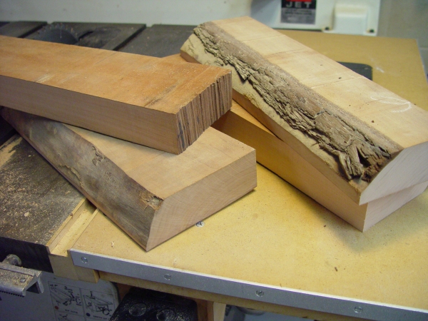
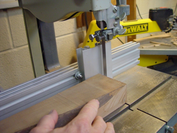
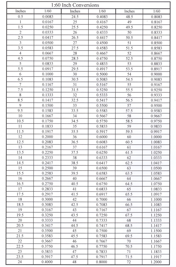
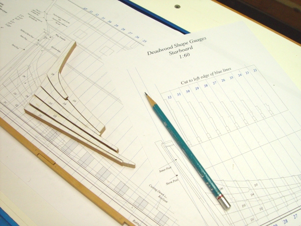
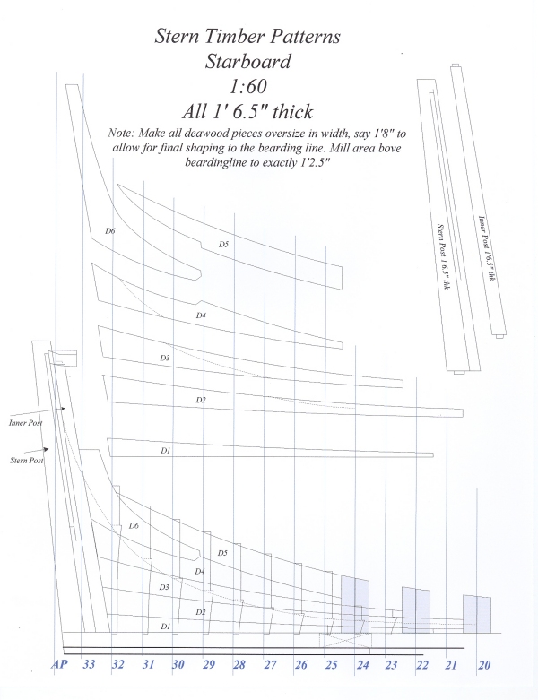
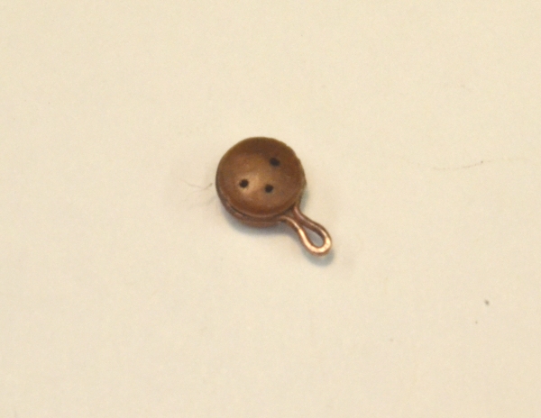
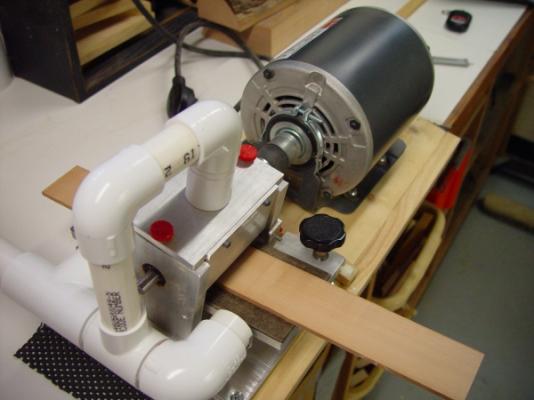
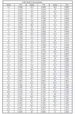
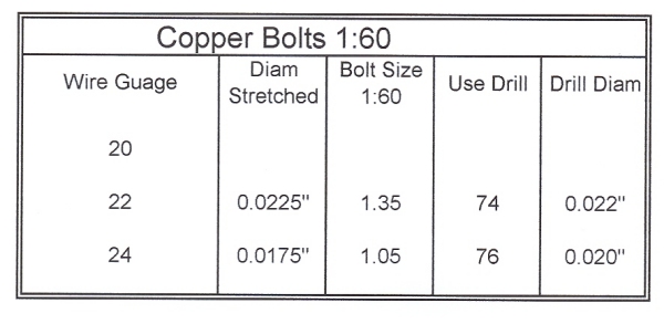
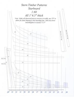
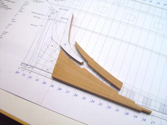
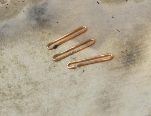
1:60 HMS Naiad 1797 Part 5 – Construction Begins original post 10/17/10 I thought I had posted this in February, but apparently I did not - so here is part 5 out of order, but here. Sorry for the inconvenience. After about 3 months of preliminaries – drafting and making preparations – construction began in early January 2010. The first parts to be fabricated were the sections of the keel, and that required scale-sized timber to be cut from the large slabs of Swiss Pear that had been patiently waiting in my lumber rack for over ten years. Pear is a beautiful wood to work with. It is hard, has clear straight grain and has a subtle reddish brown color, which I expect may darken to a richer shade over time, much like the cherry has done on my Victory model. Making Scale Timber Nothing happens until timber is brought down to size, and over the life of the project there will be a lot of that to do, so I will start with that. I started with two slabs of kiln dried, rough cut Swiss Pear, each about six feet long, ten to twelve inches wide and 2 inches thick. A few lengths of about 15 inches were cut off one of these and ripped down the middle on the band saw to yield pieces like the ones shown below. To reduce these to planks of the necessary thickness, the band-sawed edge was first hand planed flat and square to one surface. Since all four surfaces are rough, the planed surface would be used against the re-saw fence on the band saw to cut stock of small thickness as shown below. [/size] [ If a circular saw were to be used for this, then the bottom surface would also need to be planed as well – a big job without a power planer. However, I prefer the band saw because power consumption, dust and material wastage are all less on that tool. The Woodslicer blade also produces a very good surface for the next step. After the first cut, no planning was required before subsequent cuts. Stock was cut to a slightly larger thickness than needed, then reduced to final thickness and surface finish using the 1/3 HP thickness sander shown below, which was recently fitted with the pipes for dust collection – a major improvement to the workshop environment. I use 120 grit cloth paper cut from power sander belts. These last longer than plain sandpaper. The wood in the above picture gives an idea of the color and grain of the pear wood. After each pass through the sander, the thickness was measured with digital calipers until the final size was reached. Each piece was then marked with its scale thickness – in the case of the keel stock, 15 inches. Further sizing of timbers was then done on either the Preac or the 4” circular saw, depending on thickness, or on the scroll saw if curved. Dimensional conversion at 1:60 scale is not quite as convenient as 1:96, or, I suppose 1:48, so I have the table below mounted above the workbench, so I don’t need to think too hard to figure out that 15 inches is .25 inches on the digital calipers, although 15 inches is one of the easiest to remember – how about 10.5 inches? It only took a few minutes to construct this spreadsheet and a few more to mount it, but I use it constantly and it has saved hours of time – and mistakes. What would we do without Excel spreadsheets? Keel I did not take a lot of pictures during these early stages, but there is nothing too exciting to show about the keel. It has a number of vertical scarfes, which were shown on the original draft, so their proper location was not difficult. They are square, that is, lapped, joints, each with six bolts. The forward end of the keel needs to be somewhat deeper to take the box joint with the stem. The scarfes were cut manually with a razor saw and then pared with a chisel. The joints were lined with black paper to simulate the tarred flannel that was used on the prototype. I will discuss more about highlighting joints below. Copper Bolts The copper bolts for these joints were made from coiled copper wire, which was stress hardened by putting one end of a piece about 2 feet long in a vise and pulling on the other end until it broke. In addition to hardening, the wire is reduced in diameter, which will be constant for any given size wire. Below is another little spreadsheet chart posted in a convenient place showing information for bolt sizes I expect to use. I won’t clutter this series up with too many more of these charts, but they are a big help as a time saver and I wanted to highlight their use for that purpose. This one helps quickly select the right wire and drill size for a given size bolt. To install the bolts, holes of the correct diameter were drilled through the keel, one end of the wire was dipped in polyurethane glue, the wire was slipped into the hole and moved in and out a bit to distribute the glue, then clipped off leaving a stub on both sides of the keel. Finally, the joint area was cleaned with mineral spirits. When the glue dried, the next day, the ends were clipped off and filed flush. I am testing the use of polyurethane (Gorilla Glue) in this application. It expands to fill voids, adheres to metal and wood, and dries slowly enough to move in the hole easily. Some strength is added to the joint, but I’m not sure it is a lot. CA would be stronger and I expect to experiment with that as well, but with CA there is a risk of it setting before the bolt is fully inserted. This may not be a problem with the slower drying thicker grades. The false keel was then glued to the keel bottom. Joints between false keel sections were, of course, staggered between keel joints. These joints were simple angled butt joints with the lower side of the joint angled aft to allow these sacrificial timbers to slough off if the ship went aground at the bow. Aft Deadwood The next task was the construction of the aft deadwood. The buildup of the deadwood with individual timbers was not fully detailed on any of the original drafts, so I relied on the drawings for Diana in David White’s book in the Anatomy of A Ship Series, Diana. This book was very helpful in filling information gaps not covered on the original drafts or in the Shipbuilders Repository. Diana was built close the to same time as Naiad, so I felt comfortable using White’s information for Naiad where necessary. Below is a picture showing the cut out pieces of the deadwood, some parts of the keel and a sheet of patterns of sections through the deadwood, which would be used to make gauges for rough fairing of this assembly later. Using cutouts from a printed pattern sheet assures that the original drawing accuracy would be directly transferred to the wood, eliminating potential error from redrawing and/or tracing on to the wood. The pieces were then sawed out on the scroll saw and rough sanded to the final pattern line. Below is an image of the stern patterns sheet. To make this typical pattern sheet, the stern structure was copied off the large Centerline Structure drawing and pasted on this letter-sized drawing. The individual timbers, which are CAD objects on this drawing, were then individually copied and pasted on the sheet with separation between them so this one sheet could be used to cut all the individual patterns. The idea here is that a timber, for example, is drawn correctly once, as an object on one of the main drawings. It is then copied, pasted, flipped, rotated, or whatever, but when it ends up on a pattern sheet it will be precisely the same object originally drawn, eliminating error accumulation from tracing, redrawing, etc. The picture below shows further progression in the building up of the deadwood. Here, some of the lower the pieces have been fit up to their mates. They have been cleared of paper, their joint surfaces finished with sandpaper boards to fit precisely, and then glued together. Transferring Patterns Patterns for all the timbers are being glued directly onto the wood using ordinary Elmer’s Glue Sticks. With this inexpensive supermarket variety glue, patterns adhere very well to the wood and are easily removed later by wetting the paper with water, waiting a minute or so, then easily rubbing with a finger or scraping it off with an old dull razor blade. I prefer this to rubber cement for a few reasons. With Rubber Cement I sometimes have trouble getting consistent adherence and the paper is much more difficult to remove. Also, Rubber Cement leaves a moisture resistant residue on the wood and has a solvent based odor, Finally, I hate having to remove the excess off the brush every time it is lifted from the bottle. This may be personal preference, but with all this pattern gluing, glue sticks have been one of the high points of discovery so far. I leave the paper on the wood as long as possible, especially on frames, to assist in the alignment process. This doesn’t always look good in progress photos, as will be seen later, but I find it very helpful. Highlighting Joints With all the anticipated unpainted woodwork, joint definition is important. Using paper to simulate tarred flannel or caulking on every joint is not practical for strength reasons at least, so I tried out some approaches with glue providing the desired dark line. I use Titebond PVA glue for all wood joints. First, I added dry pigment to Titebond to darken it. This worked fine as long as the pigment was slurried in some water first, before mixing with the glue. This prevents it from globbing. It still has a tendency to settle to the bottom of the glue container. I discarded the use of dye, fearing penetration into surrounding wood as well as possible interference with glue strength. I finally settled on the easiest solution, and perhaps the best. Titebond makes a woodworking glue for darker woods that I have used in the past on other work. It dries to a very dark brown color. The bottle I have must be 10 years old but there has been little settling of the pigment. Using this became an easy decision and this glue is being used for virtually all the wood joints. This approach gives visible, but not overly pronounced joint lines and assured full glue strength. For planking, a different approach is contemplated, but I will save that for later. To be continued… Ed Tosti


-
Thanks, everyone. Ben, for some reason part 5 did not get posted.I will add it. Ed
-
Thank you, everyone. Greg, I am doing some research and working away at learning a new CAD program, but have made no decision yet on if, when or what - but after Naiad, I am a bit lost without a project - even with my neglected home project list - so I expect there will be one. Guy, the molded corner on the base is just a simple 1/4" radius cove. Ed
-
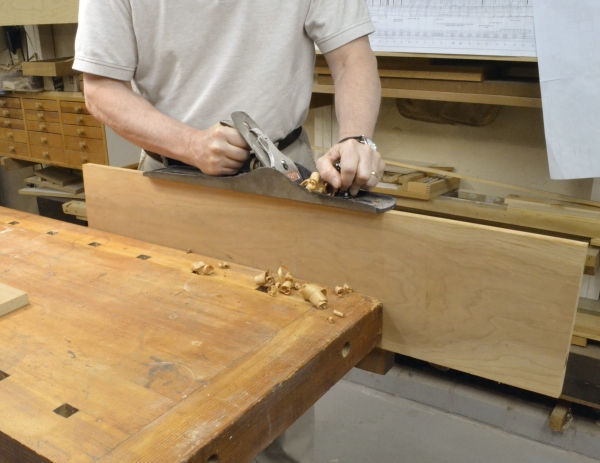
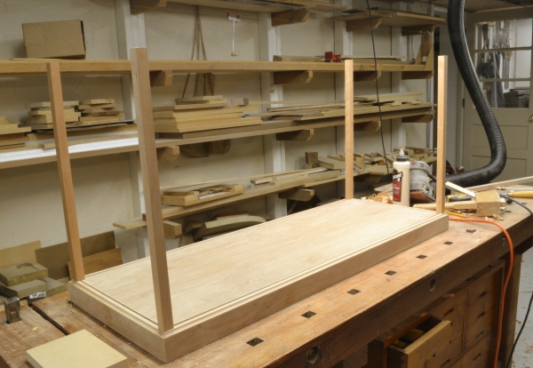
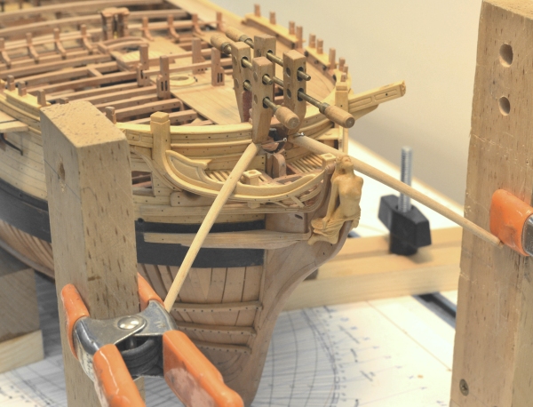
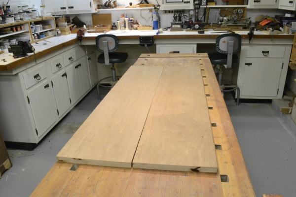
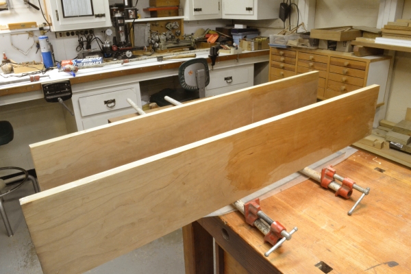
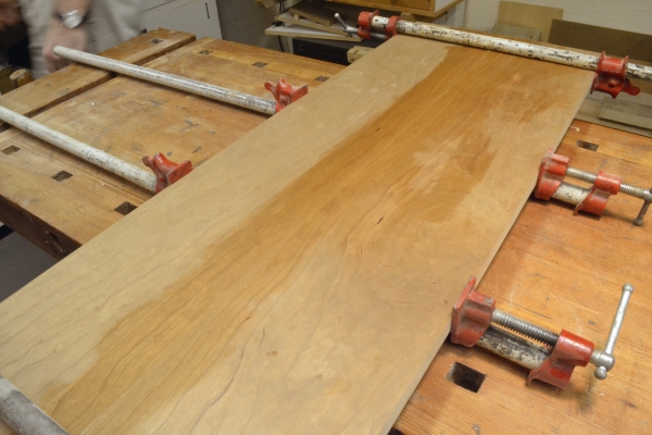
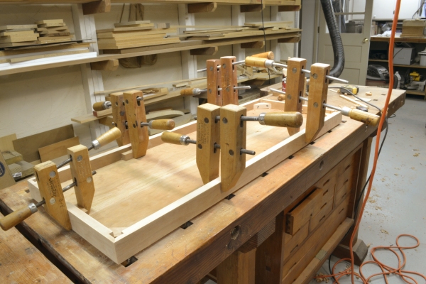
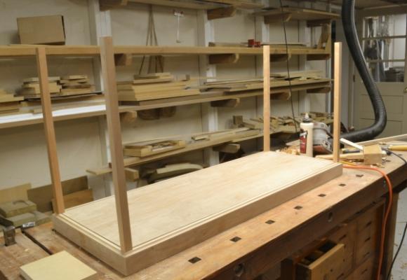
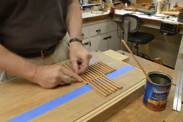
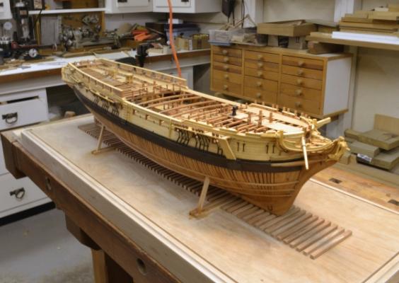
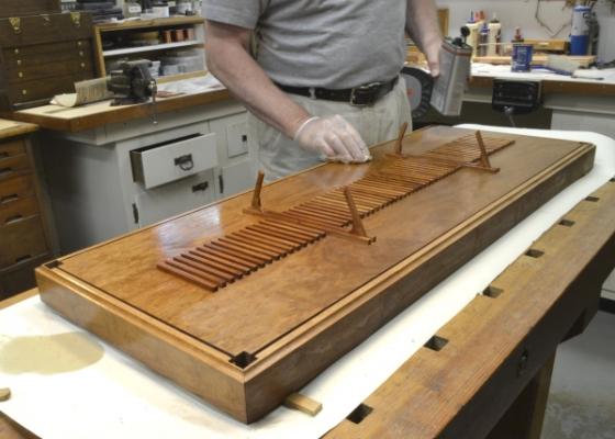
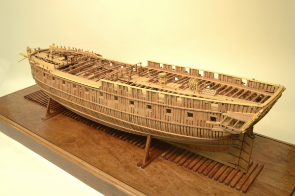
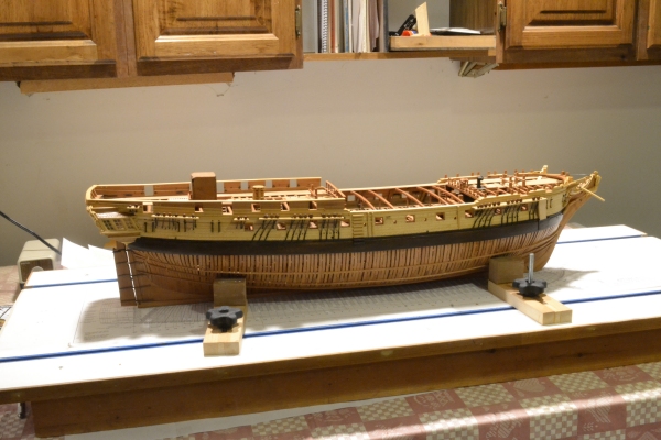
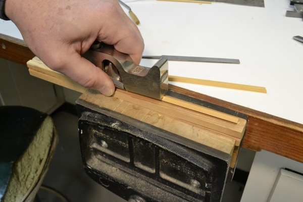
1:60 HMS Naiad 1797 Part 184 – Case Base First let me thank those of you who commented on the last post and all who have commented in the past. Your thoughts have been very much appreciated. Having started this log with the drafting of the plans, It seems reasonable to continue to the very end with the construction of the display case. In this part I will discuss the base, which I needed in order to take final photos of the model for Volume II. The case is designed so the model can be displayed on the base with the top removed. The top will later be made, glazed with cell-cast Plexiglas® sheet. The corner posts will be installed in square mortises in the corners of the base, screwed from the inside and will be removable.. In the first picture, the long wide 4/4 K/D cherry plank shown in the last part has been cut in two. It will be edge joined to form the base panel. This piece was left over from the material for the Victory case. The pieces are oriented so the grain will hide the center joint line. The faces to be joined are not quite straight and will need some work to fit neatly. In the next picture the joint edges are being squared and straightened using a 22” joiner plane. This long plane will straighten the edge, but care (and patience) is needed to make it square. Finally after a fair amount of test fitting and planing the two pieces are matched and ready for gluing. Titebond dark glue has been applied to both edges in this picture and the pieces will next be positioned and held in place with pipe clamps until dry – as shown in the next picture. This picture shows the top of the base panel. It is still damp from washing the excess glue from the surface. Most of the joint will later be covered with wood chocks to simulate a shipway of sorts. In the next picture the top panel has been cut to size and sanded. Side rails have been molded and are being fastened to the top panel using corner pieces that will also hold the vertical case stanchions, plus glue blocks along the inside corners. Since the inside corner pieces are glued on their end grain, they are also screwed to the sides. The next picture shows the case posts being fit into the corner mortises. These posts will later be cut to length and slotted to fit the glass. Note in this picture that the side rails were rabbeted on the inside top edge to form the base slots for the glass. In the next picture wood chocks for the shipway are being installed down the center. The blue tape defines the line for these and the pieces at the sides set the spacing. In the next picture the model has been brought back to mark the holes through the base. Holes were then drilled to accept the original bolts used to hold the model to the building board. The model was then set up and aligned so the side supporting struts could be fitted and glued between extended chocks as shown. In the next picture the base has been lightly stained and a polyeurthane wipe-on finish is being applied in several coats. Finally, a picture of the model on the finished base. Later, when I complete the case I will post that construction. Ed

- 511 replies
-
- 24
-

-
Gary, that last picture really captures the lines. The model just keeps getting better - if that's possible. Ed
-
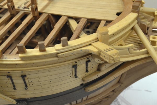
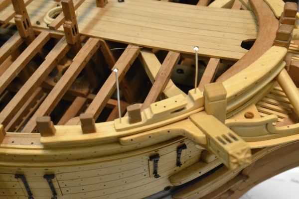
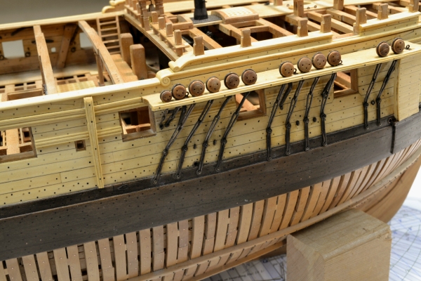
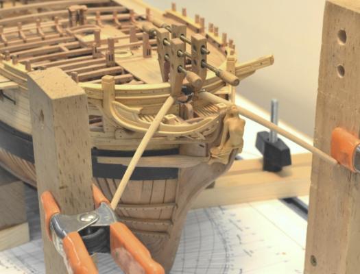
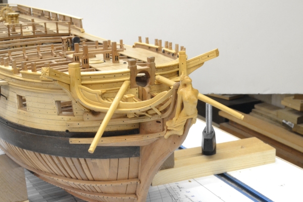
1:60 HMS Naiad 1797 Part 183 – Port Tackle Sleeves, Catblock, Horse In this part we are literally getting done to the wire with a number of odds and ends. The first picture shows the sleeves for the gun port lid tackle installed above the three ports aft. The contracts only call for shackles on the doors – no mention of tackle or sleeves, which I assume were installed later by the Navy on fitting out. I decided to install the sleeves. They are small ebony rods, glued in, then drilled out by hand. In the next picture the first step in making the cat blocks is shown. These were built up as a laminate as was done with the fixed blocks, however, these are curved and fit over the forward timberhead. They are also open at one end. The next picture shows a finished block pinned in place for gluing. The sheave is installed. It needs to line up with the aft of the three sheaves on the cathead. Two bolts plus the sheave pin are visible. Additional bolts wil replace the pins. The next picture shows both finished catblocks in place. This picture also shows the two iron horses. These were substantial (2” diameter) iron rods that connected the fore and aft ends of the main rails with a vertical stanchion in the center. They supported the fore end of the rail and also served as a safety rail. This picture also shows the two brackets over the boomkins. The very last item to be completed, except for final cleaning and finishing, was the iron knee for the quarterdeck seat transom on the starboard side. This almost-forgotten item is shown in the next picture. In the next picture Naiad has returned to her roots – on my drafting table, where it all began. In the last picture, the workbench is empty for the first time in three years – except for a couple of short interludes when it was needed for some other urgent work. In this picture some of the raw material for the case is on the bench. Since it was part of the overall project, I will cover the case construction in the next part or two. Ed

- 511 replies
-
- 17
-
-
Egen, your Euryalus looks terrific and your rate of progress is impressive. I did not cover the sleepers in Volume I, but installed them with the deck framing at each level. These are covered in Chapter 27 and 28 in Volume II and are shown on Drawing 8. As Allan has said, all these points are subject to interpretation and sources vary on detail, especially dimensions. Perhaps my following interpretation will be helpful. The purpose of the sleepers was to reinforce the horizontal transoms and secure them to the framing. According to Steel (1805) they should bolt through as many transoms as possible specifically including the wing transom in frigates. The fore and aft arms of both pair of sleepers and the wing transom knees bolt to the planking, not directly to the frames. The inner sleepers pass below the last lower deck beam and fay to the thickstuff below the lower deck clamps. The outer sleepers lower arms are above the lower deck and fay to the lower deck spirketing. The wing transom knees are scarphed into the the upper strake of lower deck spirketing but I could not be certain of exactly how that was done. Again the source is Steel. For these reasons the installation of the sleeprs and wing transom knees should not be done before the internal planking. I did not find the contracts very helpful on these particular members. For Naiad I used contracts for Artois class (1794) which included Diana which was contructed almost in parallel with Naiad and under the same Rule/Henslow joint surveyorship. I also referred to the Astrea contract which included Euryalus. They are virtually identical except for dimensions. Hope this is helpful. Ed
-
Beautiful, Gary. What do you plan to do about decking? So far, it looks like you are leaving it out to be able to see below. I like your process for making the whelps on the capstan - very precise. I used darkened glue on the facing on the bitt crosspieces to show the line. I can see your line in the pictures and I am sure it is more visible in real life. Great, as always, to see your posts. Ed
-
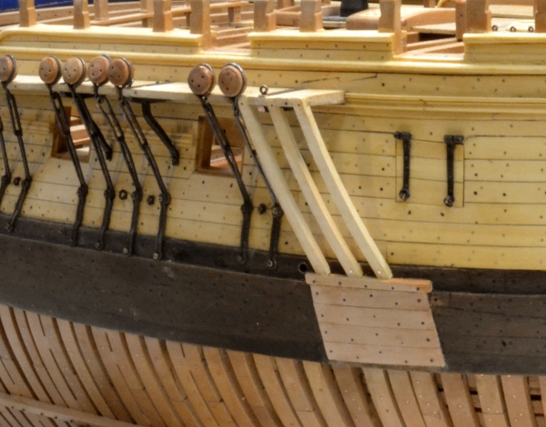
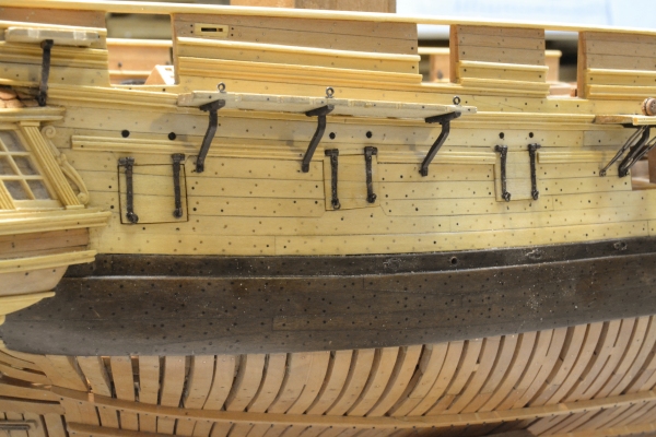
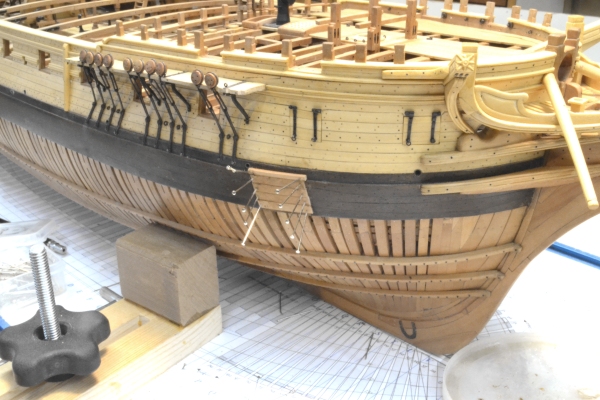
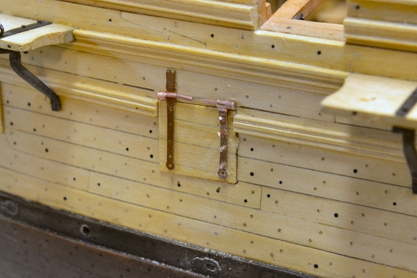
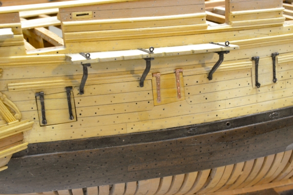
1:60 HMS Naiad 1797 Part 182 – Anchor Lining Once the channels were finished, except for a few ringbolts, the anchor lining could be installed on the finished side. The anchor lining protected the hull planking from damage by the anchor after catting, when it was being lifted and secured to the side. The first picture shows a layer of 3” thick planking being fastened to the wale. From the top of the wale to the fore end of the fore channel, a panel of three inch planks was constructed. The next picture shows the supports for these, three stanchions. I could find no spec for these so made them each a sturdy 6” x 6”. They are bolted at the channel and just above the top of the wale. The last wo pictures show the finished installation. Ed

- 511 replies
-
- 15
-
-
I had a question from a member in a pm concerning the thickness of the copper sheet I used for the Roberts plate knees that I installed on the upper deck beams. The 0.005" thick copper translates to 0.3" at 1:60 and this seems quite thin for members of this type. This is a very good question so I will share my answer here so that others may understand the logic used. My response: It was usual for plate knees to be inset into the sides of the beams and chocks. The shape of the knee would be traced on to the wood and the wood then chiselled out to some depth - in some cases to the full depth - according to Peter Goodwin in a paper on the subject. Some pictures I have seen of Victory show these as flush or almost flush with the surface of the beams. I believe the practice varied. There is a good discussion of this in Goodwin's Sailing Man-0f-War, including some pictures. I used the thin copper to simulate an almost-flush plate knee. I did not contemplates insetting these at 1:60. For an appearance of less inset, thicker material could be used. Of course thicker material requires more etching time and uses up more etchant, but other than that you could make these thicker using the masks provided without a problem or fear of being in authentic. Here is a link to Goodwin's paper on the subject. http://www.maritime.org/conf/conf-goodwin.htm Hope this helps. Ed
-
ancre Le Fleuron 1729 by rekon54 - 1:24
EdT replied to rekon54's topic in - Build logs for subjects built 1501 - 1750
Beautiful work as always, rekon. Here's another source for the perforated soldering mat - a larger size http://www.contenti.com/products/soldering/424-351.html Ed -
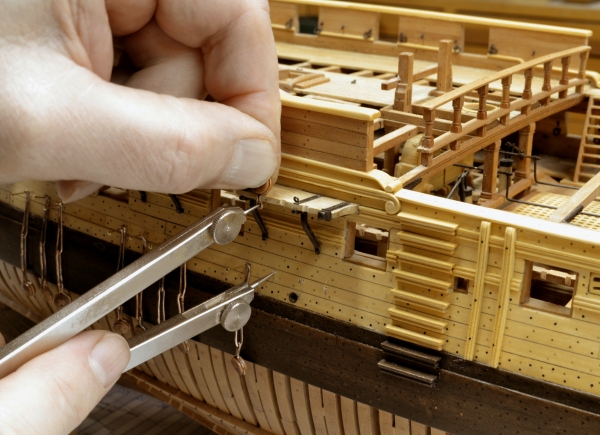
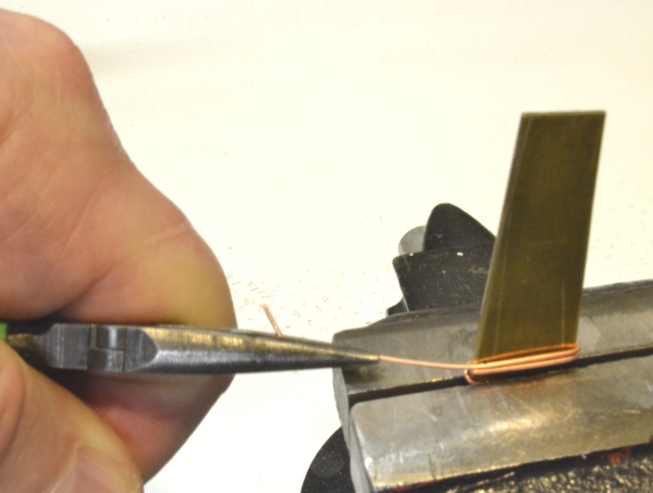
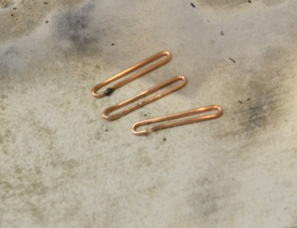
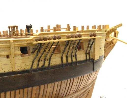
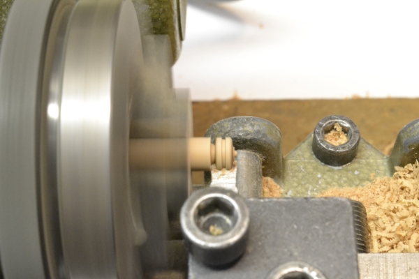
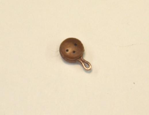
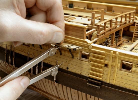
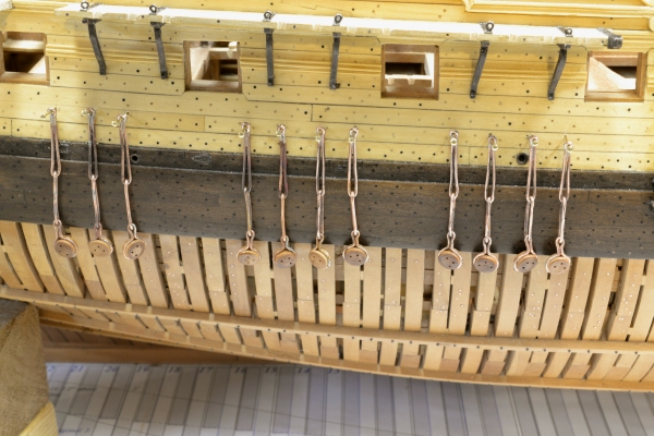
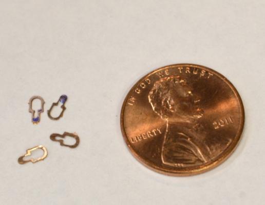
1:60 HMS Naiad 1797 Part 181– Deadeyes and Chains I will admit that making deadeye chains is one of my least favorite tasks, so it is well that it comes near the end of the project when my desire to get finished overcomes my reluctance to working on these. I find it difficult to exactly measure the required lengths of the chains and lack the patience to make all the easily deformed pieces straight. However, having said that, the task must be faced. There are a lot of steps to the process I use. I will merely summarize. Turning the deadeyes is the easy part. I use a shaped cutter as shown in the first picture. After these are polished in the lathe and parted off, the holes are drilled with the aid of the indexing head in the mill, The next picture shows a finished deadeye fitted with its binding, For the large deadeyes the bindings and chains were made from 20-gauge copper wire. When stretched this is just slightly (⅛”) larger than specified. Close enough, when considering that wire sizes are limited. Once the correct binding size is found by trial and error, the assembly shown above is used to help determine the length of the two chain loops that connect to the bolt at the top of the preventer plate. This measurement is taken as shown in the next picture. The next step is to find two links to fit this measurement. I do this by selecting two from a group made by wrapping wire around a tapered plate then parting off a number of loops of increasing size. The next picture shows the tapered plate being wrapped with pre-stretched wire. The next picture shows three stages in making a soldered loop. The lower loop in the picture is as-cut. The middle one has had its end curved to close the gap for silver-soldering. The loop at the top has had a small amount of copper-phosphorus solder paste applied and is ready for the heat. After soldering, the toe loop is crimped around a wire at the bottom end and soldered at the bottom. The middle loop is then fitted between this and a binding loop and soldered. The deadeye is then fit into he binding and shaped around the deadeye. The next picture shows a set of these hanging from pins in their final locations. After assembly the chains are test fitted at the measured location. Since the model will not be rigged they need to be taut for appearance purposes. If the chain does not fit in the measured location, I try it at other places until a nice fit is found. When the set is complete the chains are polished up, straightened and blackened. They are then installed. The next picture shows the completed chains on the fore channel. Ed

- 511 replies
-
- 16
-
-
Thanks, Maury. Me too.
-
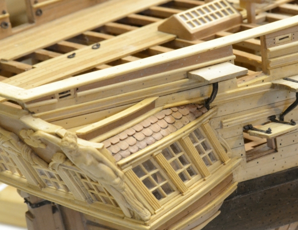
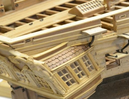
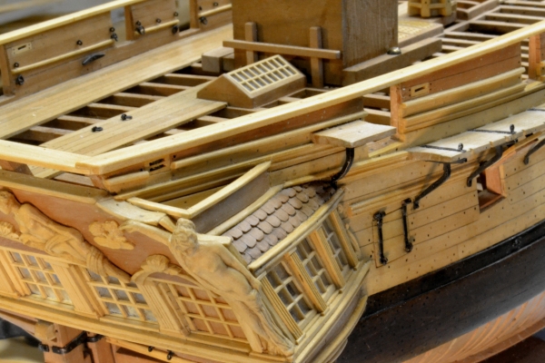
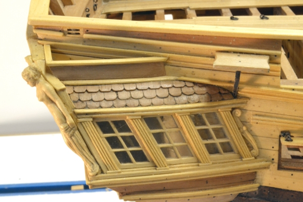
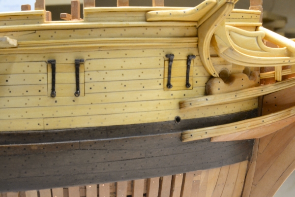
1:60 HMS Naiad 1797 Part 180– Finishing the Quarter Gallery In these last phases of construction some of the items are small and the descriptions short – like this one. The starboard quarter gallery has been worked and reworked quite a bit as I have deciphered its construction. The last remaining issue was the enclosure atop the upper finishing. My original interpretation of this is shown in the first picture. I was never satisfied with this arrangement. First, the enclosure is too low based on the original sheer draft. Also, the aft end of it is unsupported and open across the back. Fixing this has been on my “to-do” list for some time. On ships where the scallops at the ends of the taffrail are convex, there is sufficient height for the enclosure to butt against the taffrail. On the Naiad draft, these scallops are clearly concave, so at the end of the enclosure the cap rail on the taffrail is lower than the top of the enclosure. After quite a bit of searching, I finally found a reasonable reference showing a comparable configuration in John Franklins model of Egmont in the NMM. I replaced the enclosure shown above with the modified version shown below. In this construction, an athwartship section is installed to meet the height of the side enclosure at the correct height. This seems a logical solution. The enclosure acted as a cistern, undoubtedly lead lined, that provided water the toilet facilities in the quarter gallery, so with the addition of the aft section, a level barrier is provided. Here is another view. In this construction the height of the enclosure is at the height of the sheer rail as shown on the drafts and the back section completes the basin enclosure at that height - a much better solution. Ed
-
Thank you, Ian. The subject has been discussed, but basically the answer is that I use a solution of liver of sulfur for blackening copper. Almost all of the metalwork on the model is copper. Liver of sulfur does not blacken brass. With all of the knees and other metal parts secured with copper wire bolts, it is not practical to blacken everything first and avoid scraping it off in construction. Liver of sulfur affects only the copper and does not stain the wood - unless copper sanding dust is left on the surface, but I have not found that to be a problem. The solution neutralizes quickly to an inert state, but I normally wash it off with clear water immediately. The copper blackens within a few seconds. I find this to be a much more reliable method that the blue selenium based products - but sometimes they are necessary - when using brass. Ed
-
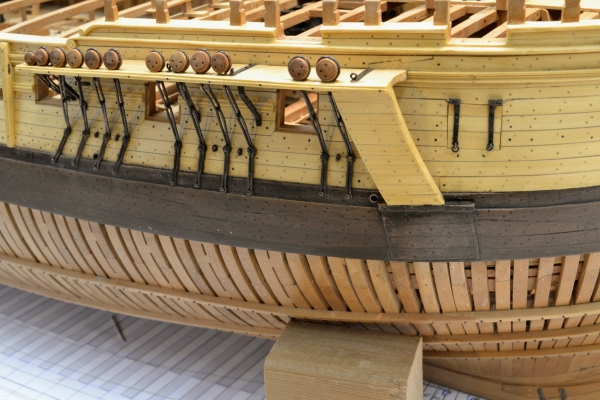
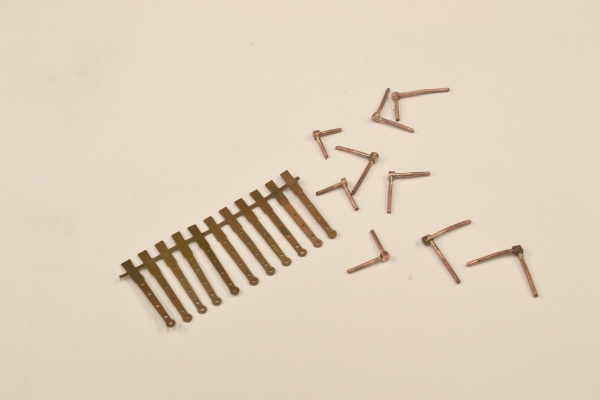
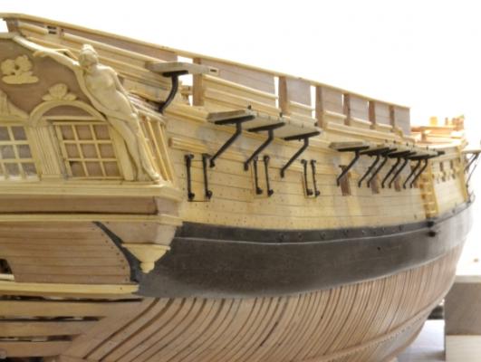
1:60 HMS Naiad 1797 Part 179– Gun Port Lids Before attacking the port lids, I had some rework to attend to. The t-plates installed under the channels were initially made too curved. Although I had drawn these correctly, I had a sketch from a book in my mind when I made them and they ended up too curved. To fix these, the channels had to be removed and each one of the plates bent straight below the angled break at the top. A minor detail perhaps, but I feel better. The corrected versions are shown below. The next picture shows the ironwork for the hinges, The straps were photo-etched and the pintles fabricated from copper wire and tubing. The pintles were silver soldered. The next picture shows hinges being fitted to one of the port lids. After bending the strap down over the hinge pin, the strap is inverted so the bent over piece is in back, where it will be secured by the top through bolt. The straps are bolted though using copper wire that is peened over to hold the straps in place. There is a small ringbolt shackle in the lowest hole through the strap. The next picture shows the three aft lids installed. There are three aft and two forward. The next picture shows the two forward lids before the copper was blackened. The next picture shows the blackened forward lids. The last picture shows the three lids aft. This picture really highlights the difference in the sheer of the outboard planking versus the flatter line of the upper deck as reflected by the port heights. The contracts specified shackles on the lids but did not require the rigging or the holes and sleeves through the side. I eventually installed the sleeves. Ed

- 511 replies
-
- 11
-
-
Thank you all. Lagrayjr, all the masks are in volume II as pdfs. Allan, I agree photo-etching is no slam dunk. I found the key steps to be cleaning the metal so there is no beading of the water when wet, "developing" the photo-resist in the dilute caustic after exposure and the aeration in the etching tank to make the etching uniform. I too have the yellow stains on my basement floor and some on the work bench - but none on me. I had no problems with the laminator even at the thick (.032) thick brass sheet for one of the stoves. It certainly feels like a black art at times. Ed
-
Hi Allan, I did all the photo-etching on Naiad using a complete kit I bought from Micromark for about $100. Its an involved process, but doable. My results were genrally good on the Roberts knees, port hinges, capstan rings, scuttle hinges. These were all simple shapes. The stove was a complicated etching, with partial etches on both sides. It too came out pretty well. There is a learning curve. I did the masks in CAD. I do prefer wood work, however. Ed
-
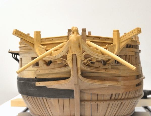
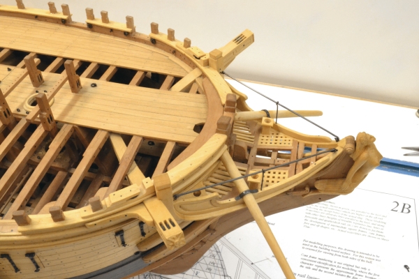
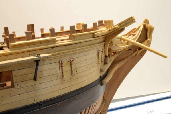
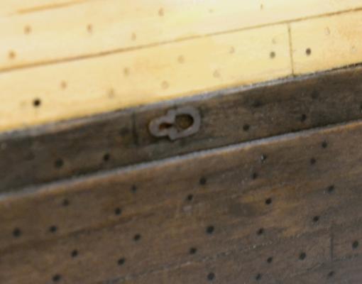
1:60 HMS Naiad 1797 Part 178– Boomkins, Scuttle Hinges The boomkins – or if you prefer, bumkins – were the only spars included in the construction contract. This is only mentioned because in determining how far to go with the model, I decided to take it to the state required by the building contracts of the time. There are a few exceptions. For example, I included the stove, although that was not included in the contract. I did not include swivel gun mounts, which were included. I believe the latter had been discontinued by Naiad’s time. The boomkins were substantial spars extending out from the head to secure the block of the fore course tack. The lengths of these were not specified, except to say that they needed to extend out to plumb with the end of the fore yard when fully braced. This required some calculations, which yielded boomkins longer than any I have seen on contemporary models, so I made them slightly shorter but still longer than those seen on Minerva and Leda in the Rogers Collection. In the first picture, a square of boxwood is being converted to a tapered octagon shape with a Stanley #92 plane. The spar will then be planed to 16 sides and finally rounded with a flat file. The boomkins slanted down and were curved. In the next picture, two pieces with significant extra length have been boiled and are held in the final downward curve by the orange clamps and the “clamped squares” that are fixed in the t-trak. After drying out, these were cut to length and installed as shown in the next picture. The boomkins are bolted to the first hawse timbers outboard of the bollards. Eventually they will be held down at the false rail with iron clamps. The next picture shows another view of these. One of the final chores was to install hinges on the ventilation scuttle just above the wale along the finished side. These were made as simple shapes, photo-etched. They are quite small and when blackened and installed on the black planking, almost invisible. The next picture shows a few. Two of these still have some mask attached. The next picture shows on of these glued on with CA glue. Ed

- 511 replies
-
- 10
-