

ChadB
-
Posts
184 -
Joined
-
Last visited
Reputation Activity
-

 ChadB reacted to Justin P. in HMS Triton by Justin P. - FINISHED - Scale 1:48 - Cross Section
Building Jig.
In the last few days I set about creating a building jig similar to other previous builders. I had thought there might be an available cross section Jig plan in the Triton downloads section as there is one for the full POF Triton build, but came up short. I experimented with trying to cut down a full size jig plan to create a cross section plan, but discovered there are a number of differences between the full build and the cross section, despite being both 1:48 scale sets of drawings. In the end I created my drawing as Im sure others have done, and went to work.
If anyone would like to use my drawing for their own work, I'll attach it here. If printed at 100% on standard letter copy paper it should be accurate. Be careful to check the lines against those of the provided drawings to be sure it is scaled and printed correctly.
Triton Jig Plan_1-48_Justin P.pdf
Having never done this before, I did sort of invent my own process which may or may not be like how others have approached this. I wound up using a 1/4" rough ply for the top and a 1/2" rough ply for bottom. I bought a sheet of 2' x 2' of each and sanded an area marked out exactly to the dimensions of the printed drawing (8.5 x 11" copy paper). I used a plain Elmers glue stick to apply the sheets. In order to really prevent the paper deforming at this scale you really need to glue out the ply instead of the sheet - the reverse of what you might do when gluing assembly parts. I had drawn guide lines on the ply to help with laying down the sheet of paper and help ensure that I have properly glued the entire area.
Using my full-size table saw I then ripped down the two sheets of ply along the edge of the copy paper. This gave me two sheets exactly 8.5 x 11" with a duplicate and well-aligned drawing mounted to each.
I then drew in registration marks to each board edge marking the keel and the center frame. This was important as there was a 1-2mm of difference in the alignment, so by using the registration marks I could clamp them together just right and drill the post holes so that when assembled all the lines would be true and aligned to one another top to bottom. I drilled those holes at exactly 3/8" and used 8" x 3/8" all-thread for the posts. This provided a very secure fit, and along with the washers and nuts created a very rigid structure.
I used a jig saw to cut out the meat of the top board interior and then a coping saw and files to finish the cut. I then used a combination of squares and the provided drawings to make all the necessary checks.
I had set this drawing up so the the distance between the top of the bottom board and top of the top board came out to exactly the distance between the floor of the keel and the upper Deck Beam Clamp mark. Incidentally, this turns out to be roughly the same as the indicated height for the full POF jig plan.
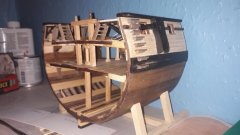
After that I positioned the keel in a jig mounted to the bottom board. The jig itself is complete and ready for frames.
As for frames, Im still working out all the steps of my process. Trial and error, but Im close. My drill press/drum sander setup is finally put together and is working well. I had intended on using a 2" diameter drum but had trouble getting it to center properly causing it to wobble intolerabely. The 1" drum works perfectly though. Ive gotten all the components of my first "test" frame cut out and ready for a final fitting at the joints. This step is hand work, so will proceed much more slowly to get it right. Hard to know what the tolerances are and how falling on either side of those tolerances will effect the end result...
Right: Fresh off band saw, ready for sanding. Left: After sanding on the drum.
Two halves of a single frame ready for final assembly.
-
 ChadB got a reaction from BobG in HMS Triton by Justin P. - FINISHED - Scale 1:48 - Cross Section
Good luck Justin! Looks like you are off to a good start! Don't be afraid of cutting out frames- it's not too bad. The key is finding the sweet spot where you don't take too much 'extra" off of the frame piece but don't leave so much that you are fairing for days. I'll be following along!
Chad
-
.thumb.jpg.6d6ee4bdbfaac2c58ecc77e7b80ae374.jpg) ChadB got a reaction from Matt D in HMS Triton by Justin P. - FINISHED - Scale 1:48 - Cross Section
ChadB got a reaction from Matt D in HMS Triton by Justin P. - FINISHED - Scale 1:48 - Cross Section
Good luck Justin! Looks like you are off to a good start! Don't be afraid of cutting out frames- it's not too bad. The key is finding the sweet spot where you don't take too much 'extra" off of the frame piece but don't leave so much that you are fairing for days. I'll be following along!
Chad
-
 ChadB got a reaction from mtaylor in HMS Triton by Justin P. - FINISHED - Scale 1:48 - Cross Section
Good luck Justin! Looks like you are off to a good start! Don't be afraid of cutting out frames- it's not too bad. The key is finding the sweet spot where you don't take too much 'extra" off of the frame piece but don't leave so much that you are fairing for days. I'll be following along!
Chad
-
ChadB reacted to Justin P. in HMS Triton by Justin P. - FINISHED - Scale 1:48 - Cross Section
Actually no. Im not doing any resawing at all. The Ryobi couldn't handle that type of work unless resawing very small billets. I ordered all my wood pre-milled to the thickness required by the parts laid-out in the Triton plans. There are a few parts, like the Keel and others that are stipulated at a thickness that Ocooch does not provide and so the Byrnes was required to take it down. The band-saw is for cutting out the keel parts from sheet stock. For example, a single side of a frame is 3/16" making the assembled frame a full 3/8" when complete. Therefore I ordered 4" x 24" x 3/16" Maple sheets to cut them from, make sense?
See here: https://ocoochhardwoods.com/scroll-saw-lumber/
As I said in my first post, ChadB did a lot of the work going through and making a list of required dimensions, I made some species substitutions, verified the required thicknesses from the plans and ordered all the wood pre-milled. There will be minimal re-thicknessing required on my end. Most of the work will be on my Byrnes table saw and the new band saw. The drill press was added to make final sanding of the frame parts easier using a drum sander attachment (total for both < $200) and because I just wanted a drill press.
-
 ChadB got a reaction from Edwardkenway in H.M.S. Triton Cross Section by Ainars Apalais - 1:48
Beautiful work as usual! I love your idea for making carriages! Could you go into a little more detail about how you made the initial block in the first photo?
Thanks!
Chad
-
ChadB got a reaction from mtaylor in H.M.S. Triton Cross Section by Ainars Apalais - 1:48
Beautiful work as usual! I love your idea for making carriages! Could you go into a little more detail about how you made the initial block in the first photo?
Thanks!
Chad
-
 ChadB got a reaction from Canute in H.M.S. Triton Cross Section by Ainars Apalais - 1:48
Beautiful work as usual! I love your idea for making carriages! Could you go into a little more detail about how you made the initial block in the first photo?
Thanks!
Chad
-
ChadB reacted to Ainars Apalais in H.M.S. Triton Cross Section by Ainars Apalais - 1:48
HI There
Finally finished my work on gun carriages.
Here will be a couple of photos from the whole process.
And final product
-
 ChadB got a reaction from GrandpaPhil in Brig Eagle 1814 by ChadB
Johann, Joe, John- thanks for the kind words!
Not a huge update, but an update nonetheless. Waterways have been installed- they ended up being more of a pain in the butt than expected because of the need to drill out the cannonball divots and making them neat. I feel that similar to treenails, it would be easy to make them look incredibly sloppy if not lined up and even. I think I got it where I'm happy with it considering I don't have a mill. In the end I also am not a fan of cutting down the deck beam ends into a tab to fit between the clamp an waterway like I did. The idea is to make things easier but I don't know if it accomplished that and also made some of my beams a bit less sturdy. In the future I would notch the clamp and waterway as was done in the original ship.
I also cut down my frame tops. When I made my frames I didn't leave enough wiggle room on top so a few were a bit under the correct height for the rail. My solution was to cut them all down 5mm below the rail height which is why they look a bit low. I will add a 5mm cap along the top that will just get covered up by planking and I figure make things a little more rigid anyway.
Thanks for looking in!
Chad
-
ChadB got a reaction from Matt D in Brig Eagle 1814 by ChadB
Johann, Joe, John- thanks for the kind words!
Not a huge update, but an update nonetheless. Waterways have been installed- they ended up being more of a pain in the butt than expected because of the need to drill out the cannonball divots and making them neat. I feel that similar to treenails, it would be easy to make them look incredibly sloppy if not lined up and even. I think I got it where I'm happy with it considering I don't have a mill. In the end I also am not a fan of cutting down the deck beam ends into a tab to fit between the clamp an waterway like I did. The idea is to make things easier but I don't know if it accomplished that and also made some of my beams a bit less sturdy. In the future I would notch the clamp and waterway as was done in the original ship.
I also cut down my frame tops. When I made my frames I didn't leave enough wiggle room on top so a few were a bit under the correct height for the rail. My solution was to cut them all down 5mm below the rail height which is why they look a bit low. I will add a 5mm cap along the top that will just get covered up by planking and I figure make things a little more rigid anyway.
Thanks for looking in!
Chad
-

 ChadB got a reaction from uss frolick in Brig Eagle 1814 by ChadB
Johann, Joe, John- thanks for the kind words!
Not a huge update, but an update nonetheless. Waterways have been installed- they ended up being more of a pain in the butt than expected because of the need to drill out the cannonball divots and making them neat. I feel that similar to treenails, it would be easy to make them look incredibly sloppy if not lined up and even. I think I got it where I'm happy with it considering I don't have a mill. In the end I also am not a fan of cutting down the deck beam ends into a tab to fit between the clamp an waterway like I did. The idea is to make things easier but I don't know if it accomplished that and also made some of my beams a bit less sturdy. In the future I would notch the clamp and waterway as was done in the original ship.
I also cut down my frame tops. When I made my frames I didn't leave enough wiggle room on top so a few were a bit under the correct height for the rail. My solution was to cut them all down 5mm below the rail height which is why they look a bit low. I will add a 5mm cap along the top that will just get covered up by planking and I figure make things a little more rigid anyway.
Thanks for looking in!
Chad
-
 ChadB got a reaction from aviaamator in Brig Eagle 1814 by ChadB
Over the last few weeks I've worked on finishing the interior of the hull. It's been oiled with Danish oil and the clamp and keel riveted as per the Eagle book. Tonight I finished installing the berthing deck beams, which will still need some kind of fastener on the end. The entire berthing deck was missing from the wreck so it is entirely conjectural. I decided to make the beams closer in the area of where the stove will go, thinking there may be additional support in that area.
Chad
-
ChadB got a reaction from aviaamator in Brig Eagle 1814 by ChadB
I started this build waaaay back in 2013 after I finished my Triton cross section, but really didn't want to start a build log until I had some substantial progress done (I'm a really slow builder). I was also lofting my own frames and lived in perpetual fear up until recently that I made some mistake that would only become apparent when I started fairing the hull and would end in the ruin of my build. I figured having a multipage build log when that happened would make it that much harder to recover my confidence. Well, I got past that point and it turns out my drawings worked, so a slow day at work seemed like a good time as any to start a log.
So- the Eagle... built on Lake Champlain in 1814 in 19 days (the irony of spending nearly six years making a model of a ship built in 19 days is not lost on me) to help Thomas Macdonough's fleet stop the British from taking control of the lake and essentially cut New England off from the rest of the country. He succeeded at the battle of Plattsburgh, helping keep the British from having any claims for territory in the Treaty of Ghent. After her long, illustrious career of a few months she was laid up in ordinary where she lasted about as long as you would expect a ship of such quality as that of one built in 19 days would last. The wreck sat on the bottom of the Poultney River until 1981 when it was rediscovered and the archaeological study started by the great people of the Texas A&M Nautical Archaeology program (a career choice I found out about 20 years too late in life).
I started the model using the book done on the study (and one worth every penny if the subject interests you), The Eagle: An American Brig on Lake Champlain during the War of 1812, and Gen Bodnar's practicum for the Eagle found on modelshipbuilder.com. The practicum was invaluable for lofting frames and giving some direction on order of building but I have pretty much moved away from it at this point. I've probably used roughly a billion other references at this point but here's a couple that have been in heavy rotation..
Robnbill's build log of the Eagle- Bill did a great job of documenting things. When I don't feel like reinventing the wheel I like to check in with his log
Coffins of the Brave: lake Shipwrecks of the War of 1812- some updated info on the eagle and have gleaned some building practices of the time from it. Excellent read.
The Texas A&M ship model laboratory model of the Jefferson- not the same builder but helped me wrap my head around drawing up a stern. Also, just a really nice model.
So anyway, that's some backstory. I don't want to make a "how-to" log like I did with my cross section and plan to just keep it picture heavy. If there's any questions feel free to ask and I'll happily answer. A few photos to cover the first five and a half years...
Starting with the plans. Frames, deadwood, etc... I tried to work off my primary source, The Eagle: An American Brig on Lake Champlain (from here on out "The Eagle book") as much as possible and make this model as accurate as possible. Drawing everything was a job and learning experience in itself.
Keel laid. Model to be made from pear, ebony, and maple
Frames started going up. The pear will be finished in Danish oil, so I had done the keel, deadwood and the sides of the frames as i went along to save having to go in between every frame later on.
..and this is the point where life outside of modeling took over for a few years. I have two little ones that I spend tons of time doing stuff with, and also moved to a house that required some attention to drag it out of the 70's. Framing moved along slowly and I wanted to put a nice stern together, which took some research (the stem and stern of the wreck were pretty much gone). Fast forward to a few months ago and inside and out are faired. The Eagle's frames were all over the place and I used those locations for the model, which is why a keen observer may think I was drunk while lofting frames.
Work has progressed a bit farther, but it's about high time to break out the real camera and retire the iphone for this build log.
Chad
-
 ChadB got a reaction from wefalck in Brig Eagle 1814 by ChadB
Johann, Joe, John- thanks for the kind words!
Not a huge update, but an update nonetheless. Waterways have been installed- they ended up being more of a pain in the butt than expected because of the need to drill out the cannonball divots and making them neat. I feel that similar to treenails, it would be easy to make them look incredibly sloppy if not lined up and even. I think I got it where I'm happy with it considering I don't have a mill. In the end I also am not a fan of cutting down the deck beam ends into a tab to fit between the clamp an waterway like I did. The idea is to make things easier but I don't know if it accomplished that and also made some of my beams a bit less sturdy. In the future I would notch the clamp and waterway as was done in the original ship.
I also cut down my frame tops. When I made my frames I didn't leave enough wiggle room on top so a few were a bit under the correct height for the rail. My solution was to cut them all down 5mm below the rail height which is why they look a bit low. I will add a 5mm cap along the top that will just get covered up by planking and I figure make things a little more rigid anyway.
Thanks for looking in!
Chad
-
 ChadB got a reaction from egkb in Brig Eagle 1814 by ChadB
Johann, Joe, John- thanks for the kind words!
Not a huge update, but an update nonetheless. Waterways have been installed- they ended up being more of a pain in the butt than expected because of the need to drill out the cannonball divots and making them neat. I feel that similar to treenails, it would be easy to make them look incredibly sloppy if not lined up and even. I think I got it where I'm happy with it considering I don't have a mill. In the end I also am not a fan of cutting down the deck beam ends into a tab to fit between the clamp an waterway like I did. The idea is to make things easier but I don't know if it accomplished that and also made some of my beams a bit less sturdy. In the future I would notch the clamp and waterway as was done in the original ship.
I also cut down my frame tops. When I made my frames I didn't leave enough wiggle room on top so a few were a bit under the correct height for the rail. My solution was to cut them all down 5mm below the rail height which is why they look a bit low. I will add a 5mm cap along the top that will just get covered up by planking and I figure make things a little more rigid anyway.
Thanks for looking in!
Chad
-
 ChadB got a reaction from bdgiantman2 in Brig Eagle 1814 by ChadB
Johann, Joe, John- thanks for the kind words!
Not a huge update, but an update nonetheless. Waterways have been installed- they ended up being more of a pain in the butt than expected because of the need to drill out the cannonball divots and making them neat. I feel that similar to treenails, it would be easy to make them look incredibly sloppy if not lined up and even. I think I got it where I'm happy with it considering I don't have a mill. In the end I also am not a fan of cutting down the deck beam ends into a tab to fit between the clamp an waterway like I did. The idea is to make things easier but I don't know if it accomplished that and also made some of my beams a bit less sturdy. In the future I would notch the clamp and waterway as was done in the original ship.
I also cut down my frame tops. When I made my frames I didn't leave enough wiggle room on top so a few were a bit under the correct height for the rail. My solution was to cut them all down 5mm below the rail height which is why they look a bit low. I will add a 5mm cap along the top that will just get covered up by planking and I figure make things a little more rigid anyway.
Thanks for looking in!
Chad
-
 ChadB got a reaction from Ainars Apalais in Brig Eagle 1814 by ChadB
Johann, Joe, John- thanks for the kind words!
Not a huge update, but an update nonetheless. Waterways have been installed- they ended up being more of a pain in the butt than expected because of the need to drill out the cannonball divots and making them neat. I feel that similar to treenails, it would be easy to make them look incredibly sloppy if not lined up and even. I think I got it where I'm happy with it considering I don't have a mill. In the end I also am not a fan of cutting down the deck beam ends into a tab to fit between the clamp an waterway like I did. The idea is to make things easier but I don't know if it accomplished that and also made some of my beams a bit less sturdy. In the future I would notch the clamp and waterway as was done in the original ship.
I also cut down my frame tops. When I made my frames I didn't leave enough wiggle room on top so a few were a bit under the correct height for the rail. My solution was to cut them all down 5mm below the rail height which is why they look a bit low. I will add a 5mm cap along the top that will just get covered up by planking and I figure make things a little more rigid anyway.
Thanks for looking in!
Chad
-
ChadB got a reaction from Edwardkenway in Brig Eagle 1814 by ChadB
Johann, Joe, John- thanks for the kind words!
Not a huge update, but an update nonetheless. Waterways have been installed- they ended up being more of a pain in the butt than expected because of the need to drill out the cannonball divots and making them neat. I feel that similar to treenails, it would be easy to make them look incredibly sloppy if not lined up and even. I think I got it where I'm happy with it considering I don't have a mill. In the end I also am not a fan of cutting down the deck beam ends into a tab to fit between the clamp an waterway like I did. The idea is to make things easier but I don't know if it accomplished that and also made some of my beams a bit less sturdy. In the future I would notch the clamp and waterway as was done in the original ship.
I also cut down my frame tops. When I made my frames I didn't leave enough wiggle room on top so a few were a bit under the correct height for the rail. My solution was to cut them all down 5mm below the rail height which is why they look a bit low. I will add a 5mm cap along the top that will just get covered up by planking and I figure make things a little more rigid anyway.
Thanks for looking in!
Chad
-
 ChadB got a reaction from G.L. in Brig Eagle 1814 by ChadB
Johann, Joe, John- thanks for the kind words!
Not a huge update, but an update nonetheless. Waterways have been installed- they ended up being more of a pain in the butt than expected because of the need to drill out the cannonball divots and making them neat. I feel that similar to treenails, it would be easy to make them look incredibly sloppy if not lined up and even. I think I got it where I'm happy with it considering I don't have a mill. In the end I also am not a fan of cutting down the deck beam ends into a tab to fit between the clamp an waterway like I did. The idea is to make things easier but I don't know if it accomplished that and also made some of my beams a bit less sturdy. In the future I would notch the clamp and waterway as was done in the original ship.
I also cut down my frame tops. When I made my frames I didn't leave enough wiggle room on top so a few were a bit under the correct height for the rail. My solution was to cut them all down 5mm below the rail height which is why they look a bit low. I will add a 5mm cap along the top that will just get covered up by planking and I figure make things a little more rigid anyway.
Thanks for looking in!
Chad
-
ChadB got a reaction from Canute in Triton Cross Section Timber List
I think the list I put together above when I did it will suit you well if you are ok with extra wood. I am overly cautious on these things and definitely ordered more than needed, but there were definitely screw-ups aplenty, so I was happy I had it handy. I would highly suggest skipping the thickness sander and ordering everything to size initially. Put that money towards a scrollsaw and a cheap disc sander if it's burning a hole in your pocket as those two tools will help you the most throughout the build, IMO.
Chad
-
ChadB got a reaction from Ainars Apalais in Brig Eagle 1814 by ChadB
Schooners- thanks for checking in! Sorry I am just seeing your message now as I have been off the forums pretty much since my last update and nose down in decking or just enjoying the summer! Now that the rain has arrived back in the PNW I will most likely be getting back to work!
JpR62, stuglo- thanks for the kind words and for checking in!
Not a huge update and kind of a boring photo from my phone but deck framing has been completed. I am currently working on waterways.
-Chad
-
 ChadB got a reaction from archjofo in Brig Eagle 1814 by ChadB
Schooners- thanks for checking in! Sorry I am just seeing your message now as I have been off the forums pretty much since my last update and nose down in decking or just enjoying the summer! Now that the rain has arrived back in the PNW I will most likely be getting back to work!
JpR62, stuglo- thanks for the kind words and for checking in!
Not a huge update and kind of a boring photo from my phone but deck framing has been completed. I am currently working on waterways.
-Chad
-
ChadB got a reaction from archjofo in Brig Eagle 1814 by ChadB
Thanks guys. I have a good friend who does ships and plastic models who turned me on to evergreen plastics when I was lamenting how much of a pain making the stove was going to be. It was a great material for some of the smaller details. I ended up using just about everything under the sun- plastic, aluminum, brass, copper, piano wire, HO train axles, and scale chain. Here is a photo before airbrushing that shows the hodgepodge (the black is plastic parts cannibalized from the first stove)!
Chad
-
ChadB got a reaction from archjofo in Brig Eagle 1814 by ChadB
Not a huge update but a couple small projects that took quite a bit of time. Finished the pump well and shot locker and the Brodie Stove. I did quite bit of research on the well and shot locker and really never nailed down anything better than this. I'm happy with it and my kids thought it was awesome that the little sliding windows actually worked. The Brodie stove is actually my second one- the first I completed and then realized that it was too big. I had gotten lazy and pretty much copied the size directly from TFFM books. Second go around followed scale best I could (the stove on the Eagle was the one pulled out of the Alert- the first capture of the war by the Essex) and added a bit more detail I was able to find on a model from the Royal Museums Greenwich**. The stove will go somewhere safe until it's ready to go in. Next up is deck beams and some metalwork for the outside of the hull.
Chad
** https://collections.rmg.co.uk/collections/objects/37331.html