


pirozzi
-
Posts
843 -
Joined
-
Last visited
Content Type
Profiles
Forums
Gallery
Events
Posts posted by pirozzi
-
-
The amount you paid for this kit and the problems you are experiencing is to unreasonable to believe. This looks like a great ship and will make a great model, but the manufacture is sure ripping people off. All these problems should have been fixed before the kit got released. Obviously, the end product was never built from this kit. When you pay as much as this kit cost, we have a right to expect better products, with better reseach etc.
You are doing a great job solving these problems and are creating a great model. Kepp up the good work.
Hi Gary,
In defense of Euromodels, I don't fault them for the problems I am having. Yes, the kit is very expensive, mostly because of the numerous metal castings and materials. This kit however is so much like a scratch build that very little is defined in instructions and drawings as is with most kits. The plans are really excellent and if the builder uses them very carefully before making any complex moves with the build, it should turnout OK. The problems I am having is that I was spoiled with other kits like the SOS, which had more detailed instructions, even though they were flawed. This kit requires the builder to really have a scratch build mentality, which is new to me. As I gain more experience here it is becoming easier to progress. I can't emphasize enough that this kit is an extremely difficult and challenging project. I thought I was a pretty advanced builder until I started this.
 I have made some mistakes and had to cover them up, but the more I work on this, the more confident I have become. It is so challenging that I find it difficult to walk away from the work bench. I have found myself waking up from a sound sleep with a solution to something that was bugging me during the day. So I either wrote it down, or went to the work bench at 4 in the morning to try it. This is so much fun! I do warn anybody thinking of building this kit to give it a long thought, but it is the best project I have started to date.
Vince P.

- GLakie, CaptainSteve, Ponto and 5 others
-
 8
8
-
-
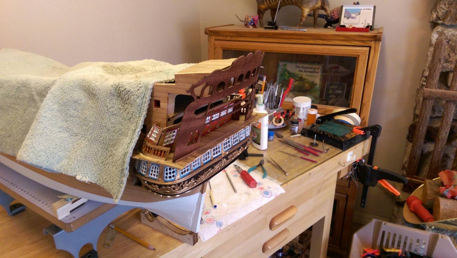
Btw. Does your admiral let you do your model INSIDE THE HOUSE? I've been delegated to the garage because of the dust!
Hi Greg,
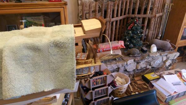
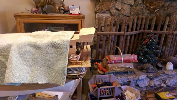
We have a big house and the admiral allowed me to convert the living room with the pool table in it to my workshop. Yes, dust is a problem, but as long as I keep it all in that room I won't walk the plank.

Vince P.
- GLakie, CaptainSteve and mtaylor
-
3
-
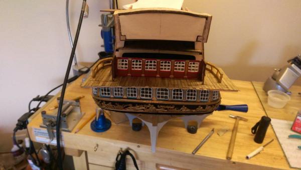
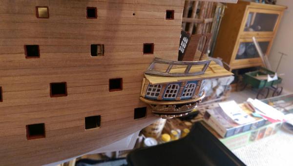
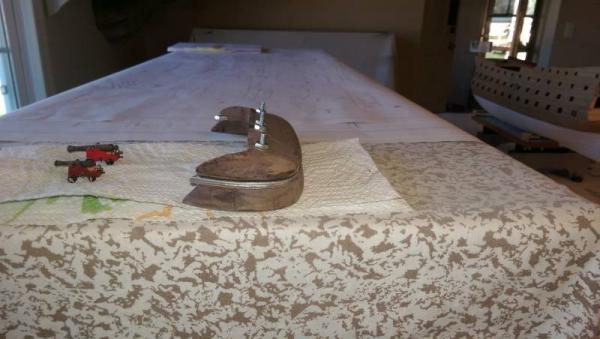
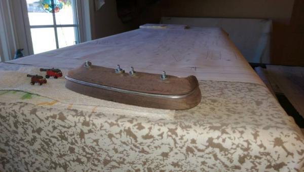
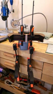
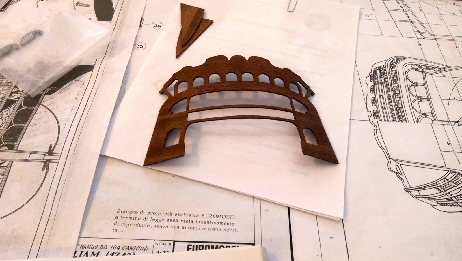
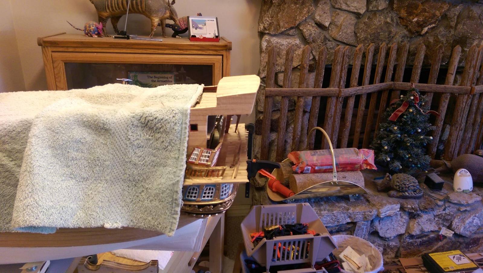
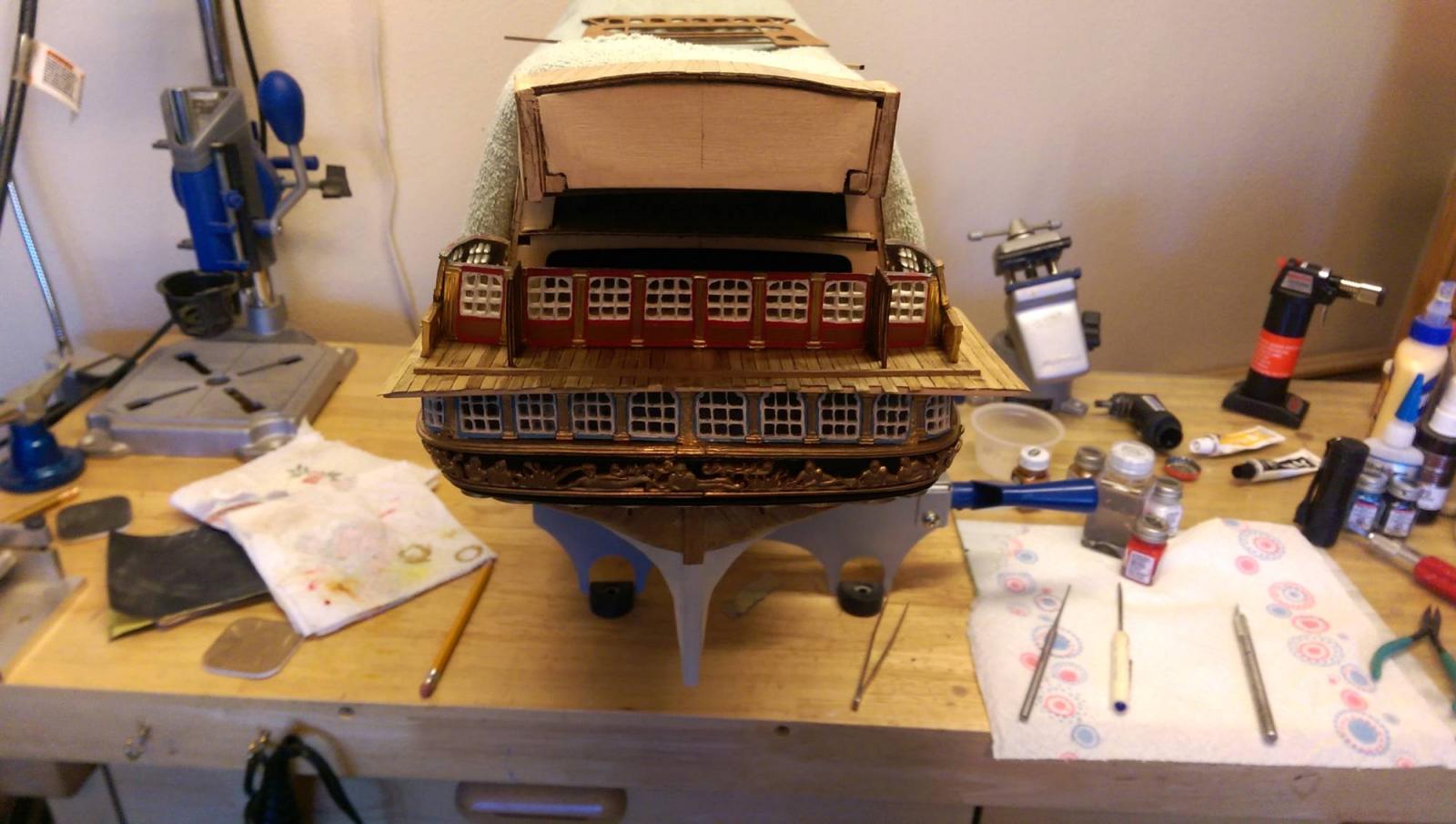
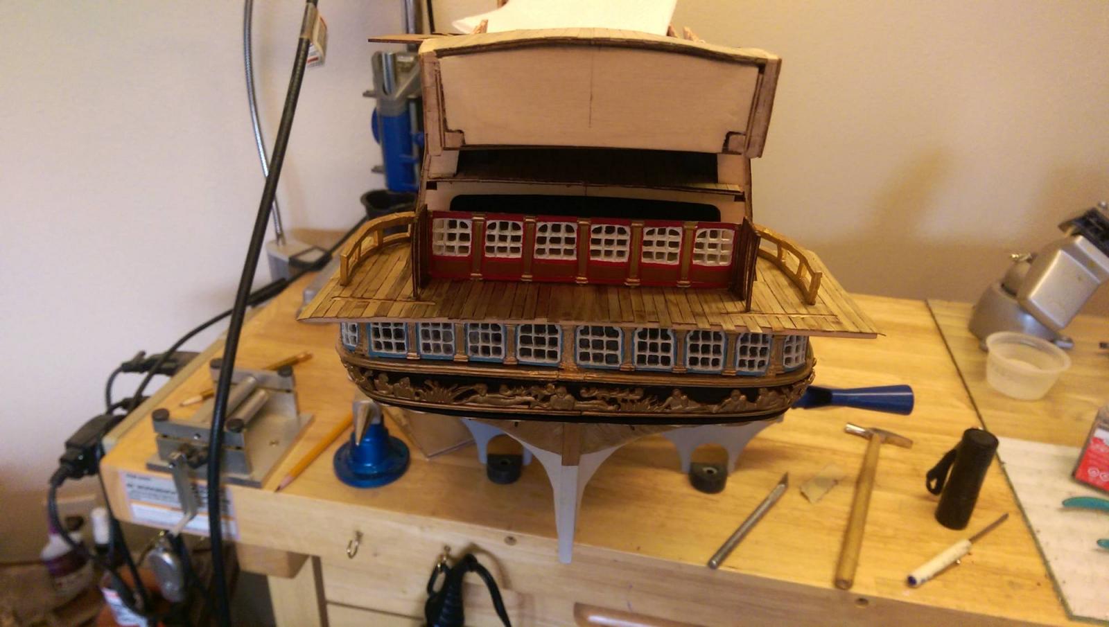
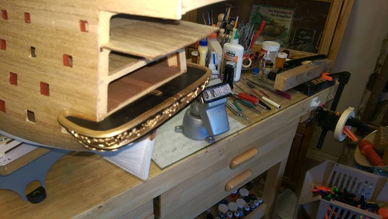
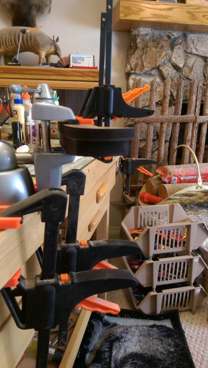
OK, the pot did the trick. The transom piece retained the curve needed to wrap it around the end of the decks.
I placed the transom piece without gluing, just to see how it fits. It fits very well and will be easy to secure properly once I get to that point.
 I still have to create the upper deck gallery windows and place them before the transom piece. The transom piece will also need to be planked on both sides.
Vince P.


-
G'day Vince
Good idea, but is the curve on the pot the same as what you need, or is it close?
Greg
Hi Greg,
I think it will be a little more than needed. With the curve in place I can then just place it on the deck ends and clamp it to the exact curve needed. There will be just a slight adjustment and no fear of it breaking. I picked a cooking pot big enough to approximate the curve needed.
Vince P.
-
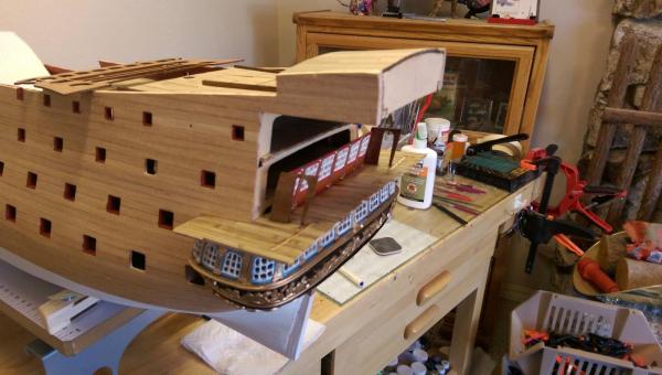
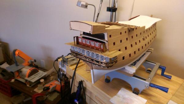
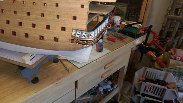
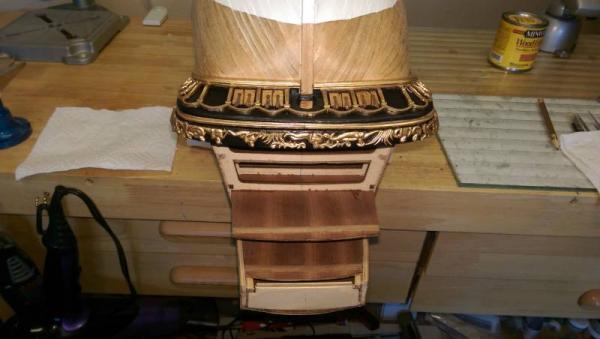
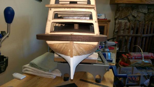
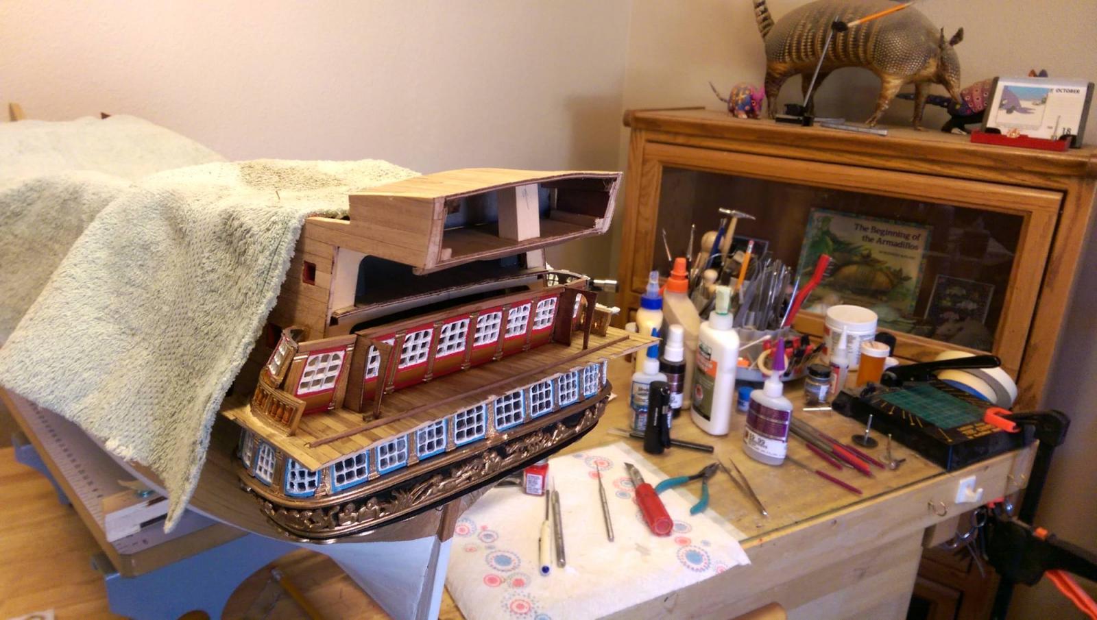
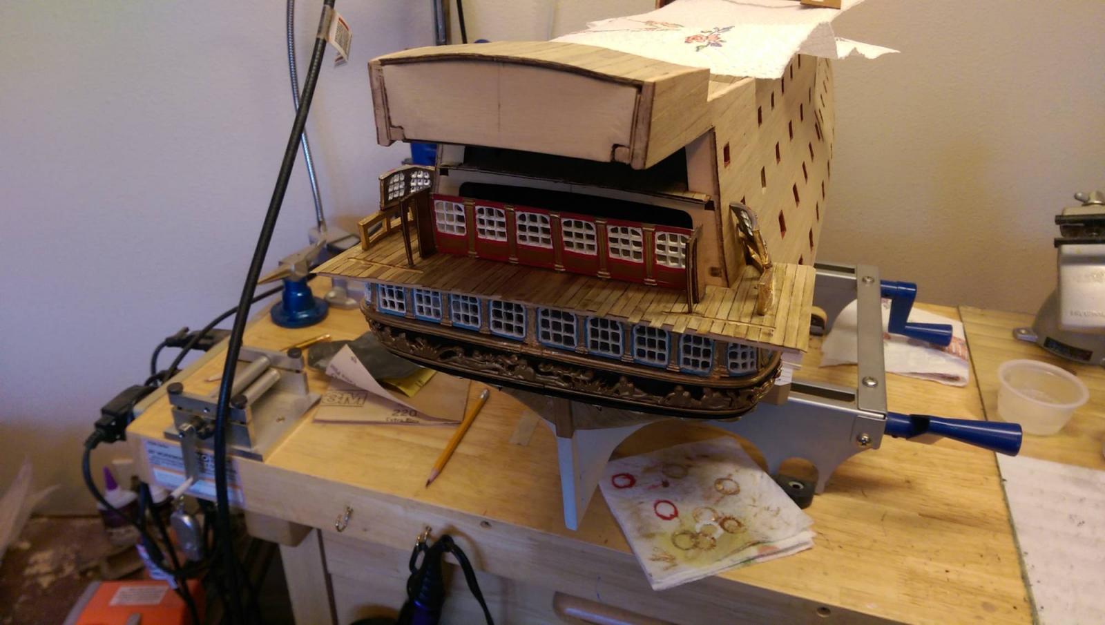
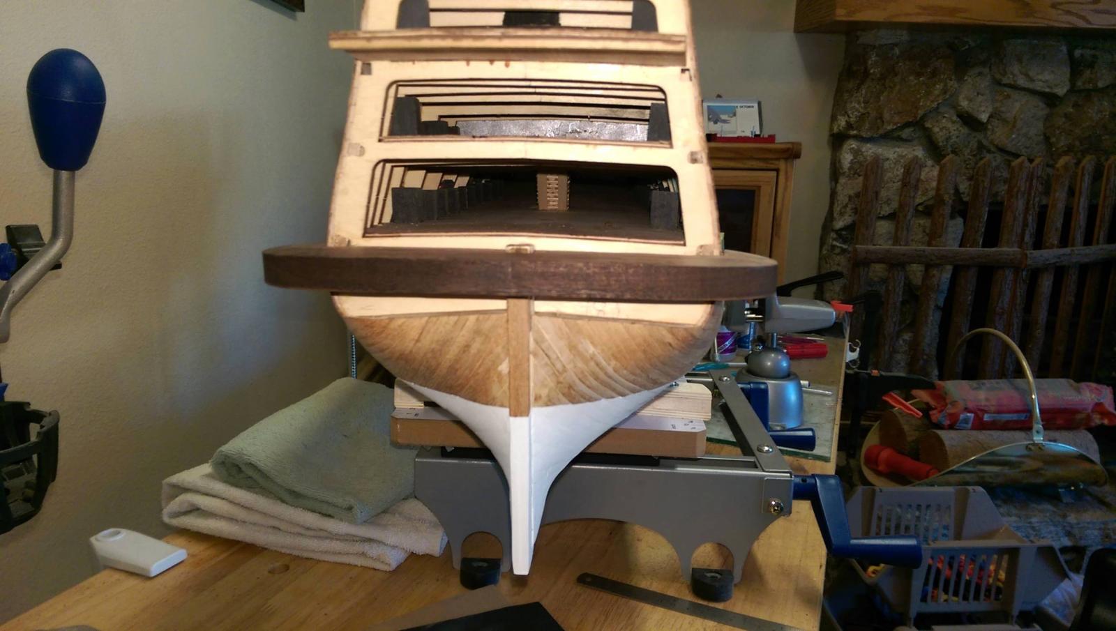
Before placing the transom piece, an aligment needs to be made with all of the gallery deck ends. It became apparent that the poop deck extends out too far. I needed to trim it off considerably and relocate it. I knew I would have to make some adjustment, just not that much.
In retrospect, if I had to do it over, I would not have placed the poop deck at all until the transom was in place. I seem to remember one of our experienced builders on this forum pointed that out to me.
You live and learn. The photos show it trimmed and positioned correctly to receive the transom.Vince P.

-
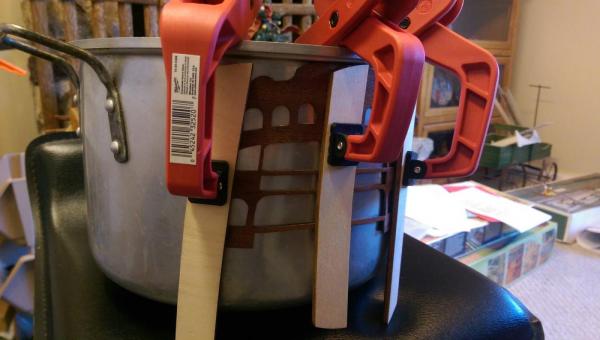
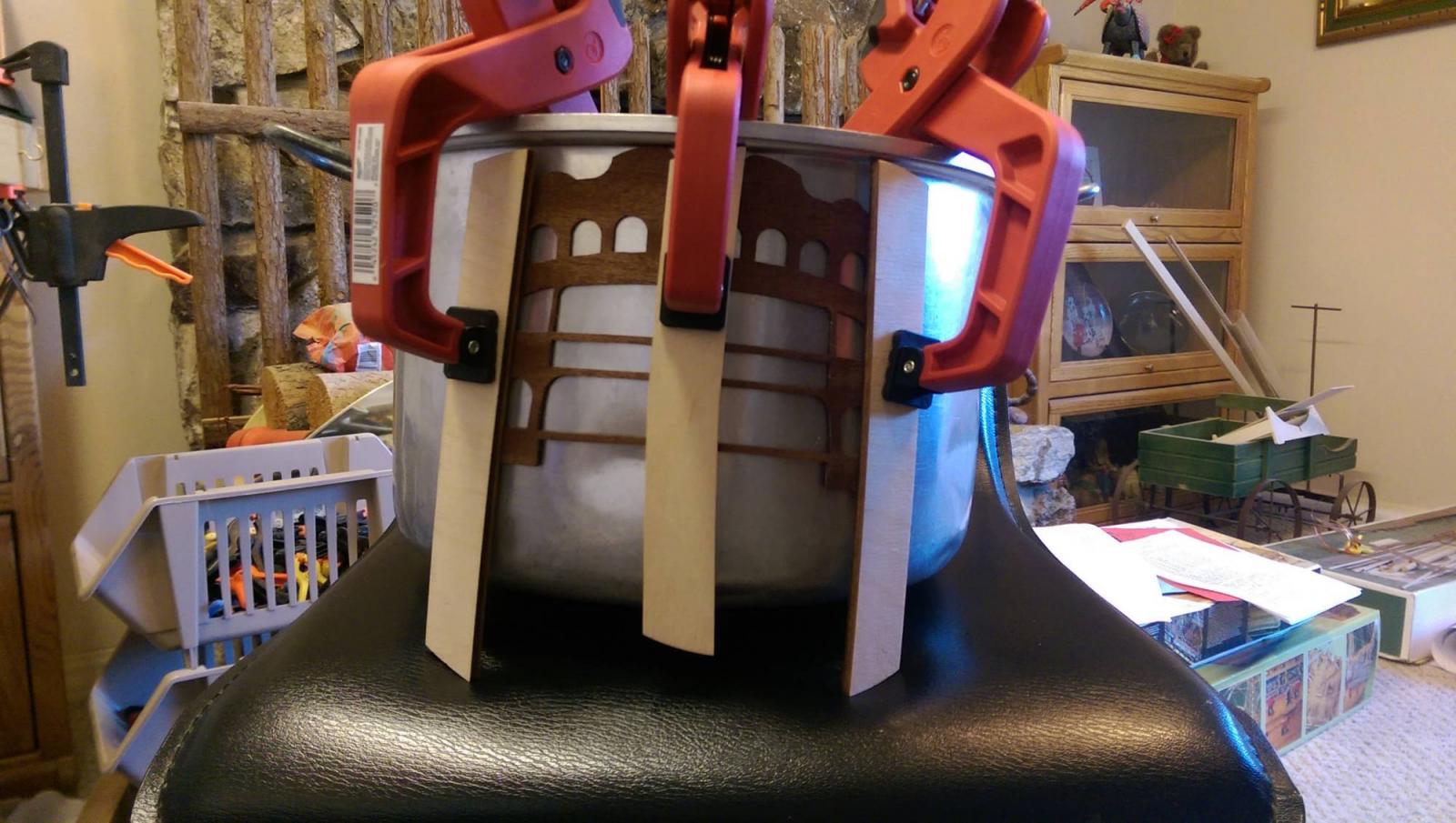
The transom piece needs to be bent to follow the deck contours. It is made of thin plywood and very brittle. It would most certainly break if pushed to meet the needed curve. I soaked it in an ammonia solution like I used for planking and then got the bright idea to use one of the Admiral's big cooking pots. I slowly bent it around the outside of the pot when it got soft and clamped it in place. I then used a hair dryer on high heat to dry it off. It is still there. I will remove it and see what curve it maintains. It didn't break though.
Vince P.

-
-
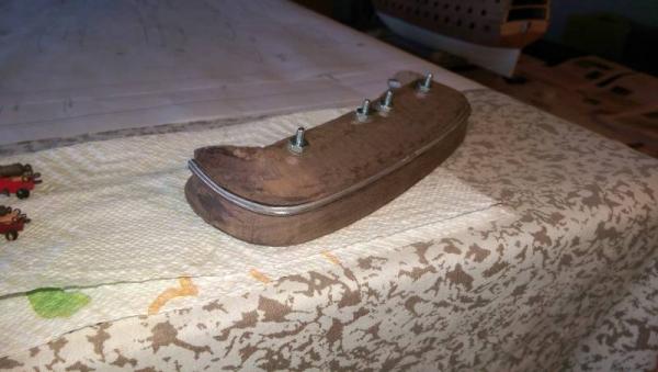
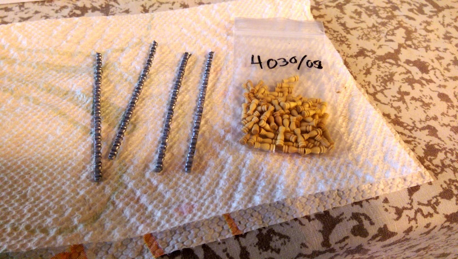
The bannisters for the railing had to be added. The kit provides metal decorative strips that must be cut to form stanchions, and they are ok, but I decided to use carved wood stanchions instead. I think they look better. These were 8mm made of boxwood from my stash. I painted them a medium brown.
Vince P.


-
-
Still working on building up the transom. It is very slow tedious work. Every single piece has to be custom fit and there are no clear plans or dimensions to work with. And, as antcipated, nothing fits correctly. I am relying heavily on photos of completed models on the Euro and other websites for some inclination on how this is supposed to look. Pete's reference notes and Julier's build log are also helpful here. It seems that every piece relies on all of the other pieces to fit together. This requires placing other pieces temporarily to fit each piece as you go. If you miss considering just fitting one piece, you could wind up with a piece later on not fitting at all which requires removing other pieces and readjusting. This has happen to me and is a real nightmare.
These photos show the middle deck railing ends. The railing is actually 4 pieces and the 2 end ones must be mounted first. The 2 middle pieces can not be added until the transom back is installed later on.
Vince P.
- DenPink, cristikc, CaptainSteve and 2 others
-
5
-
G'day Vince
Looooking great. I assume that you are going to put lights in the ship because you are making clear windows? Forgot your previous posts mate
Havagooday
Greg
Hi Greg, I had not thought about putting lights in her. I just did not like the metal windows in the kit and decided to cut them out and use a window film to make the glass panes look realistic.
Vince P.
-
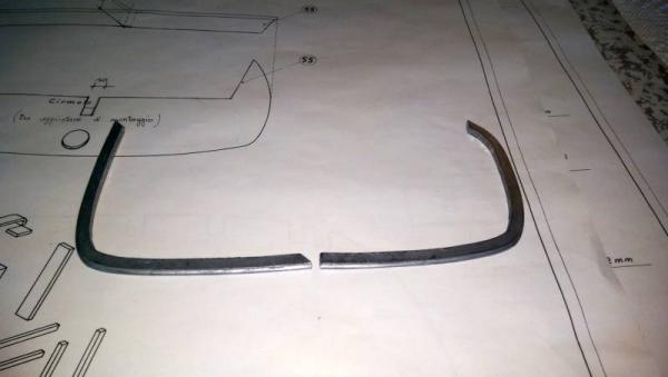
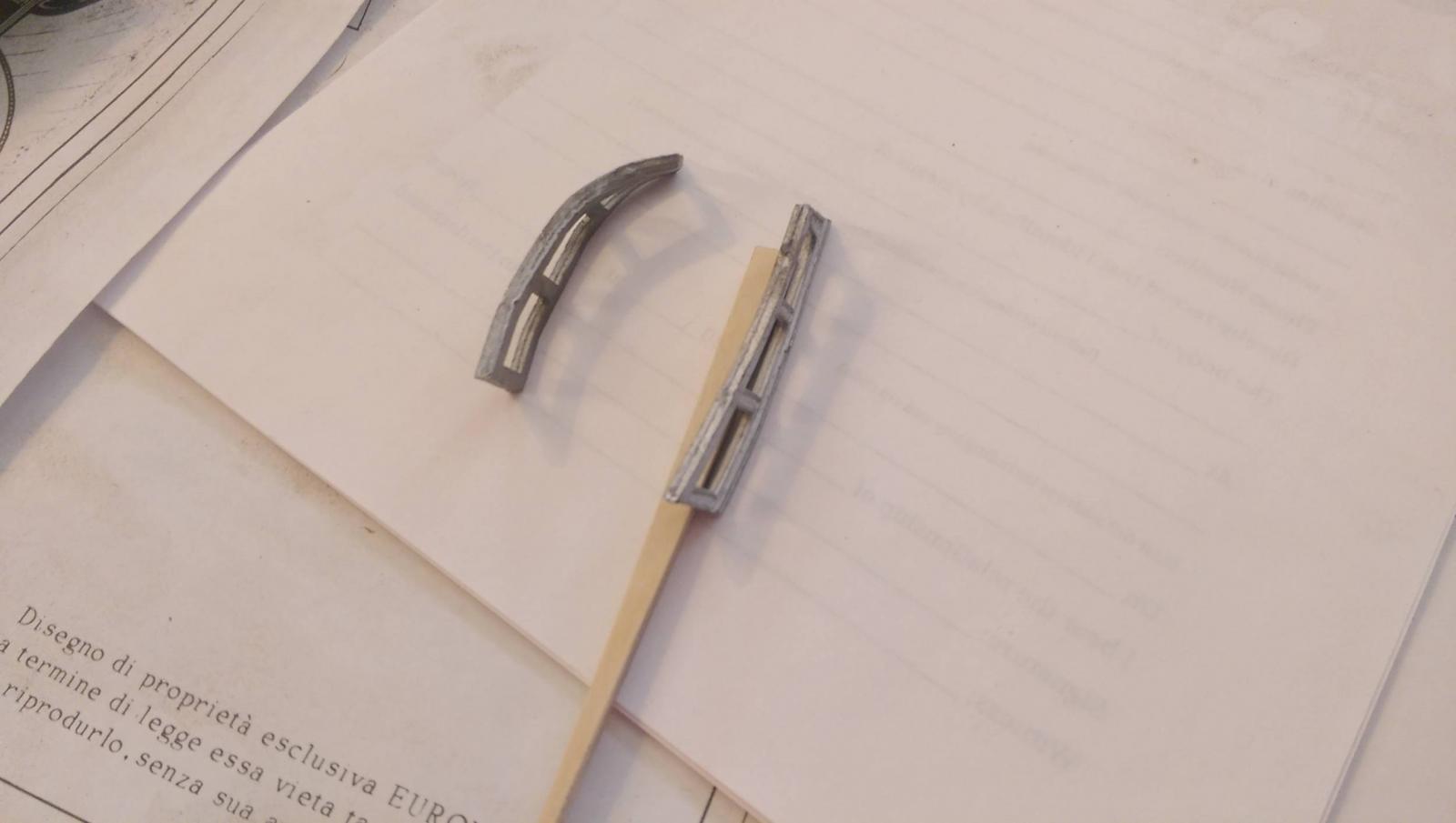
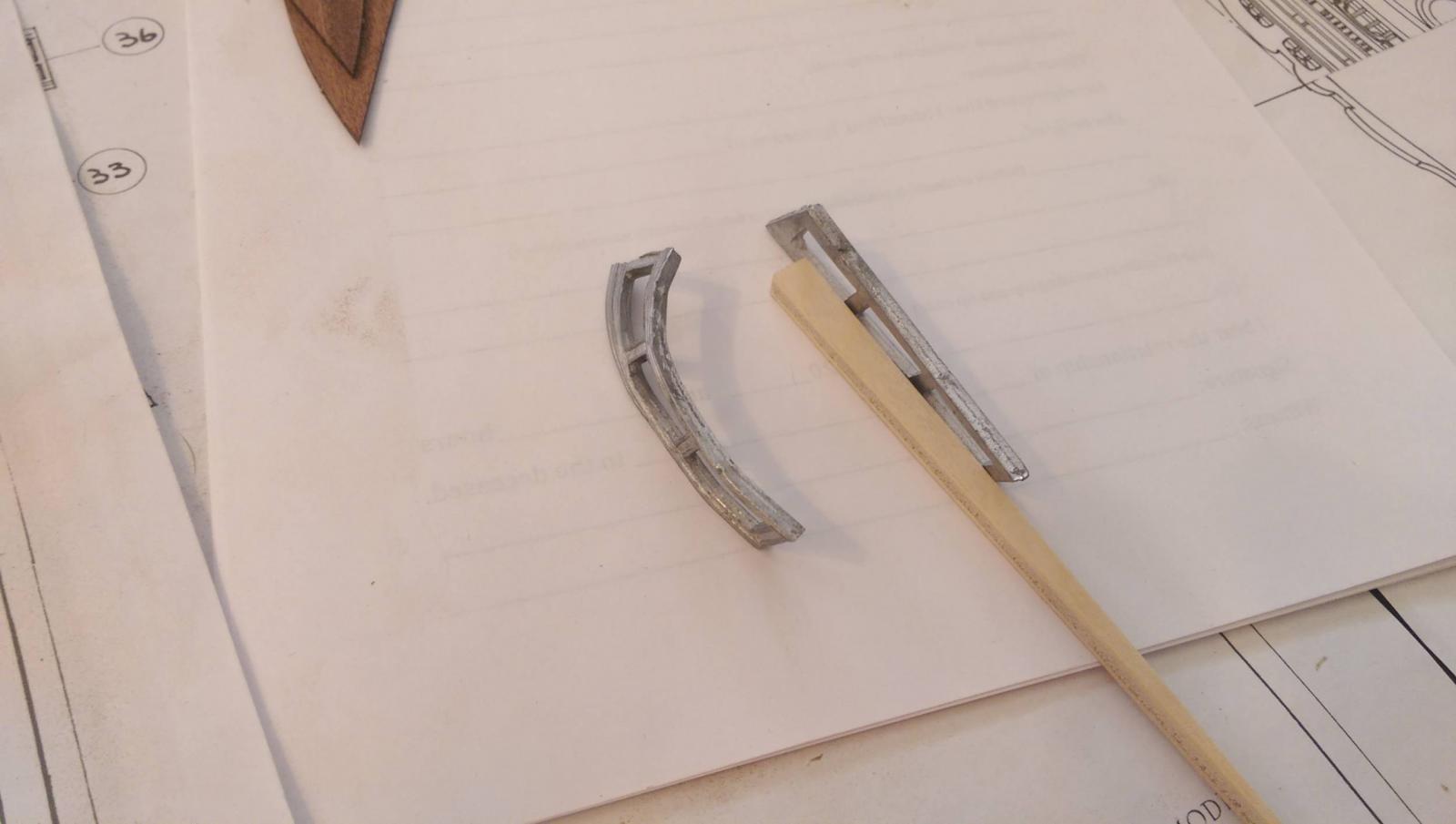
The side railings for the middle gallery deck must be contoured significantly as well as filed in order to follow the gallery curves. Once again, a small torch and very careful hammering was needed to do this without breaking them. The last 2 photos show them before and after reshaping.
Vince P.
- GLakie, CaptainSteve, cristikc and 3 others
-
6
-
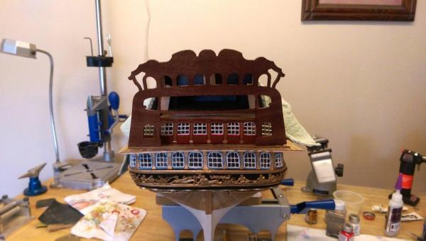
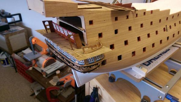
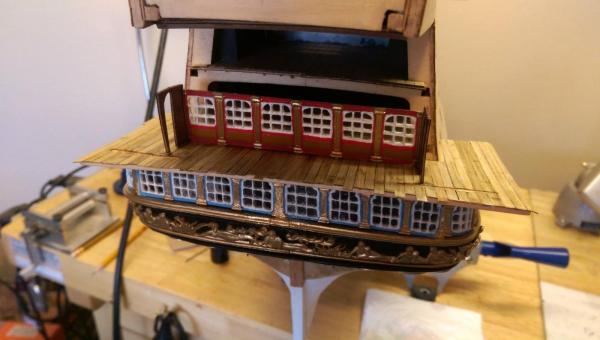
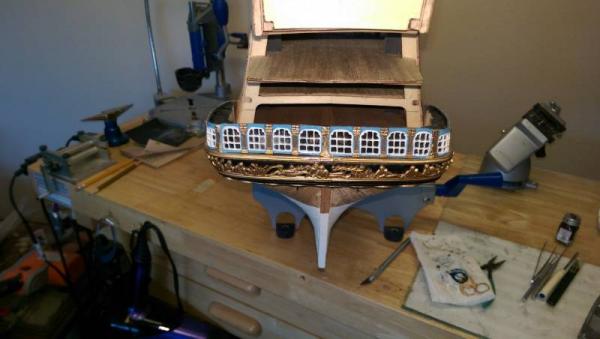
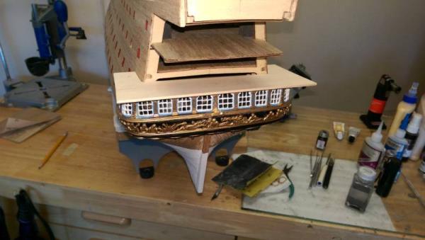
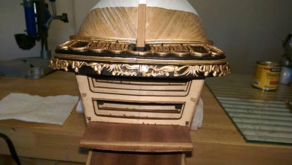
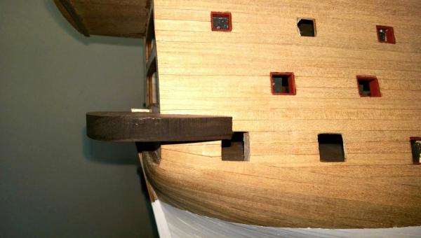
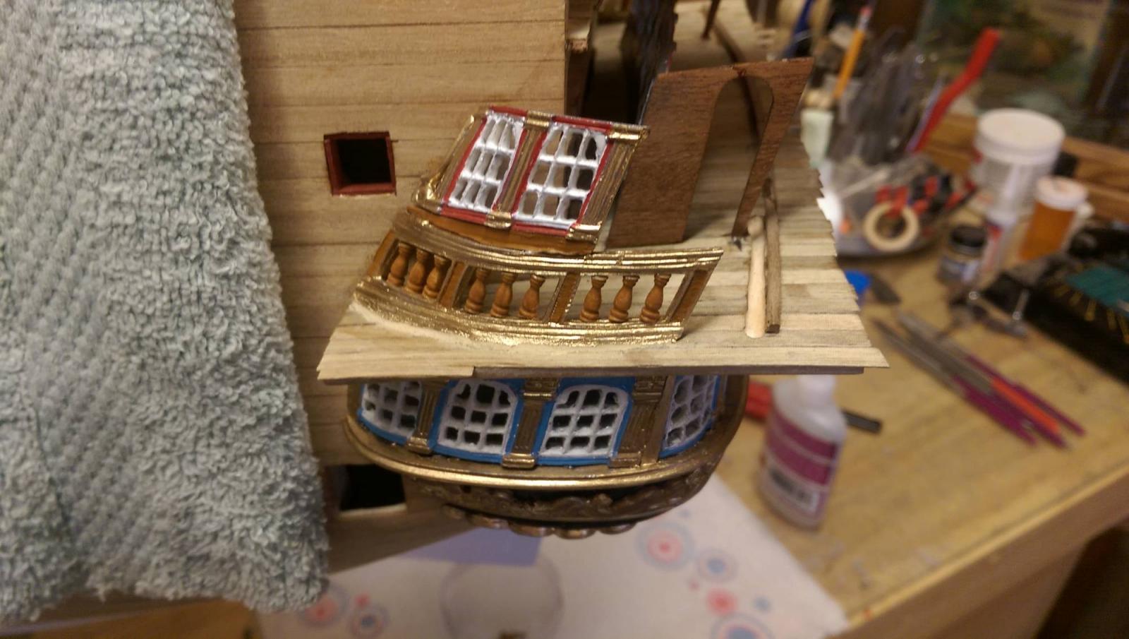
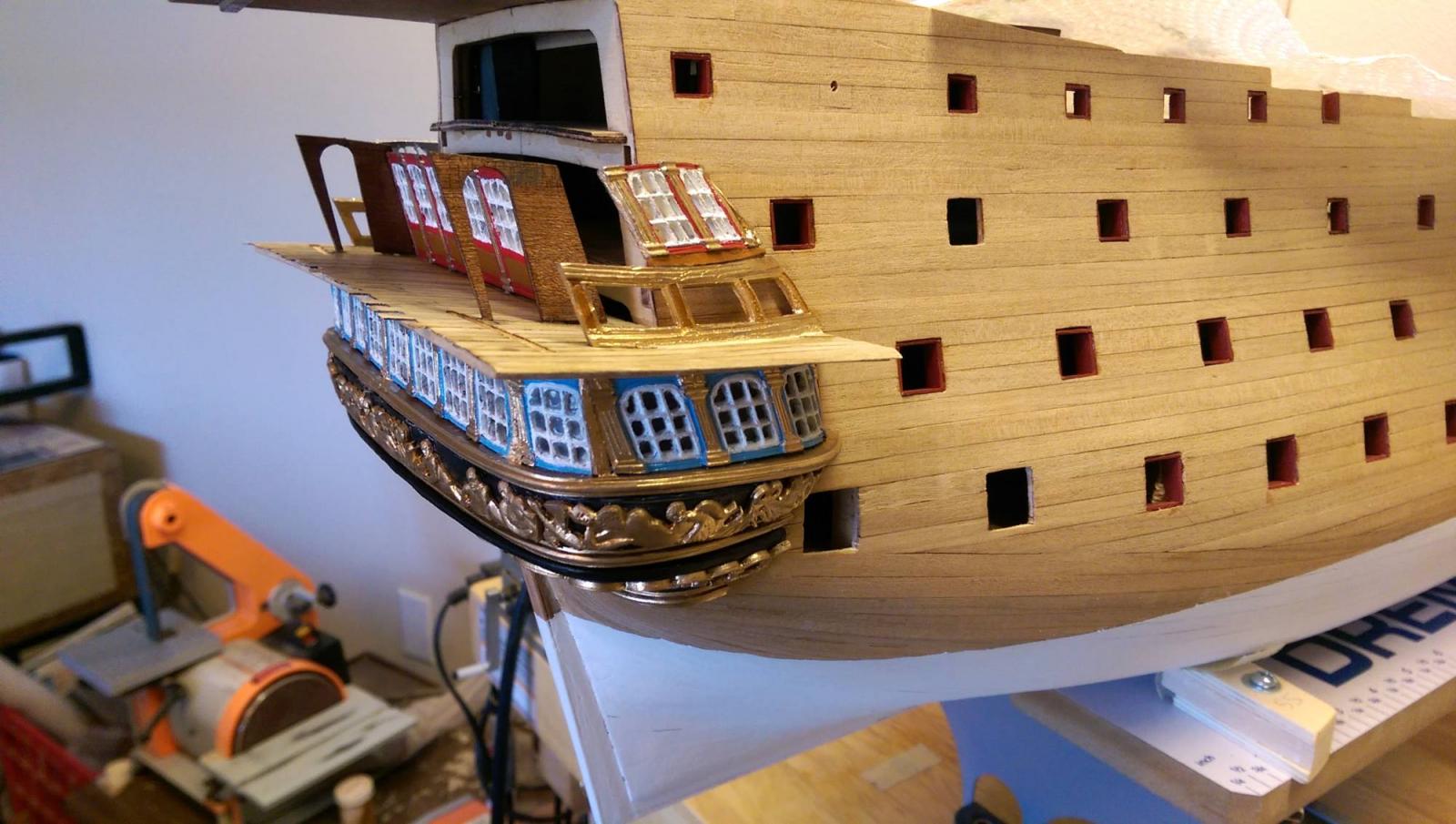
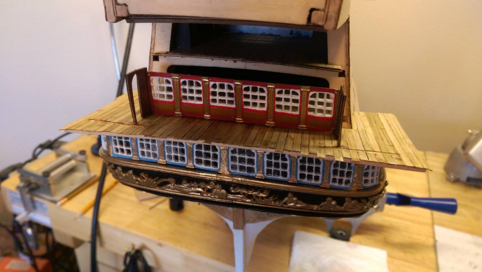
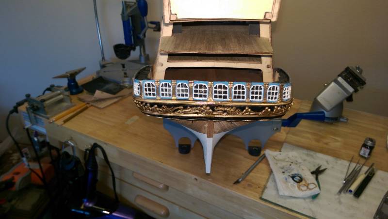
The middle gallery deck has been planked and the window section has been mounted. Two slots are cut in to the deck to take the bottom of the transom backing, which will be placed after the upper deck and windows are installed.
Next up will be to continue the middle gallery windows around to the hull sides and install the ballestrade railing around the edge of the decking. Once that is done, the deck will be trimmed back to the curve of the stern and a trim added to this edge.
Vince P.
- DenPink, marktiedens, gjdale and 8 others
-
11
-
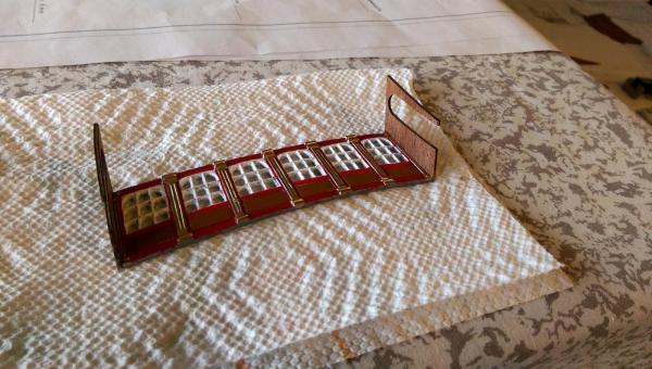
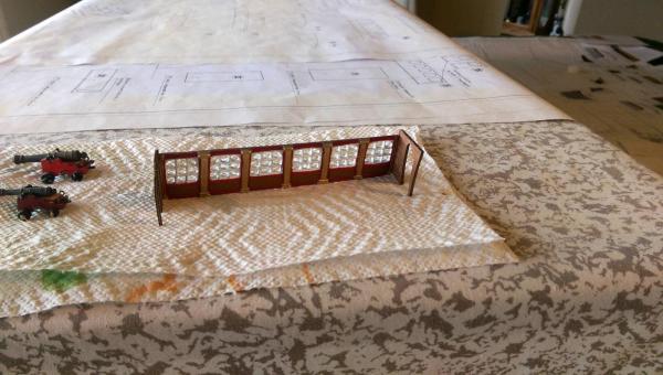
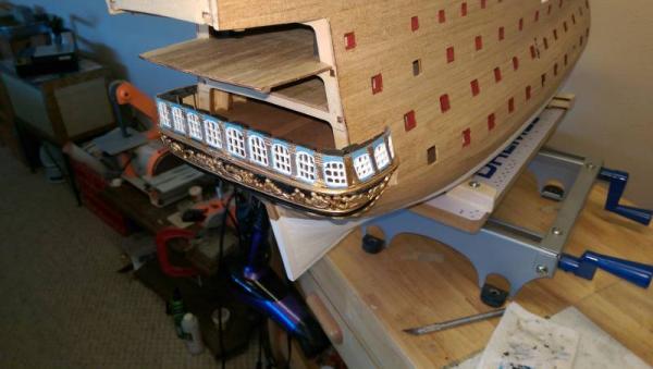
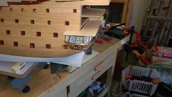
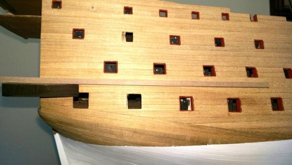
The middle gallery windows are ready for the window glass. These windows are the first set which are recessed on the transom. Locating where to place these is critical to the placement of the actual transom, which butts up against to 2 outer doorway panels on the ends of these windows. The plans are not much help here at all.
Vince P.
-
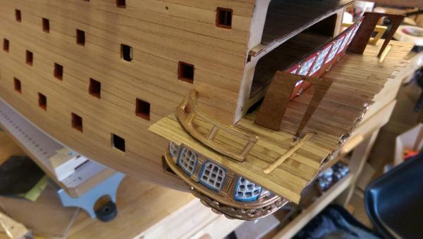
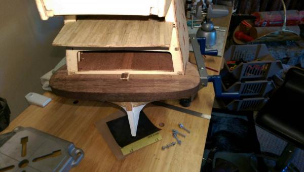
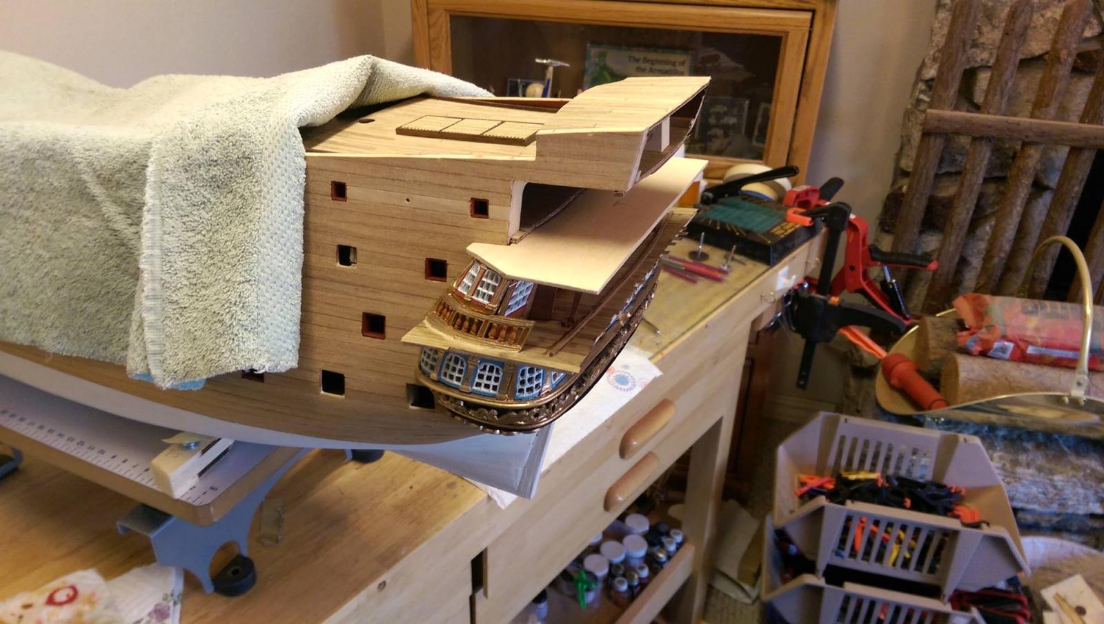
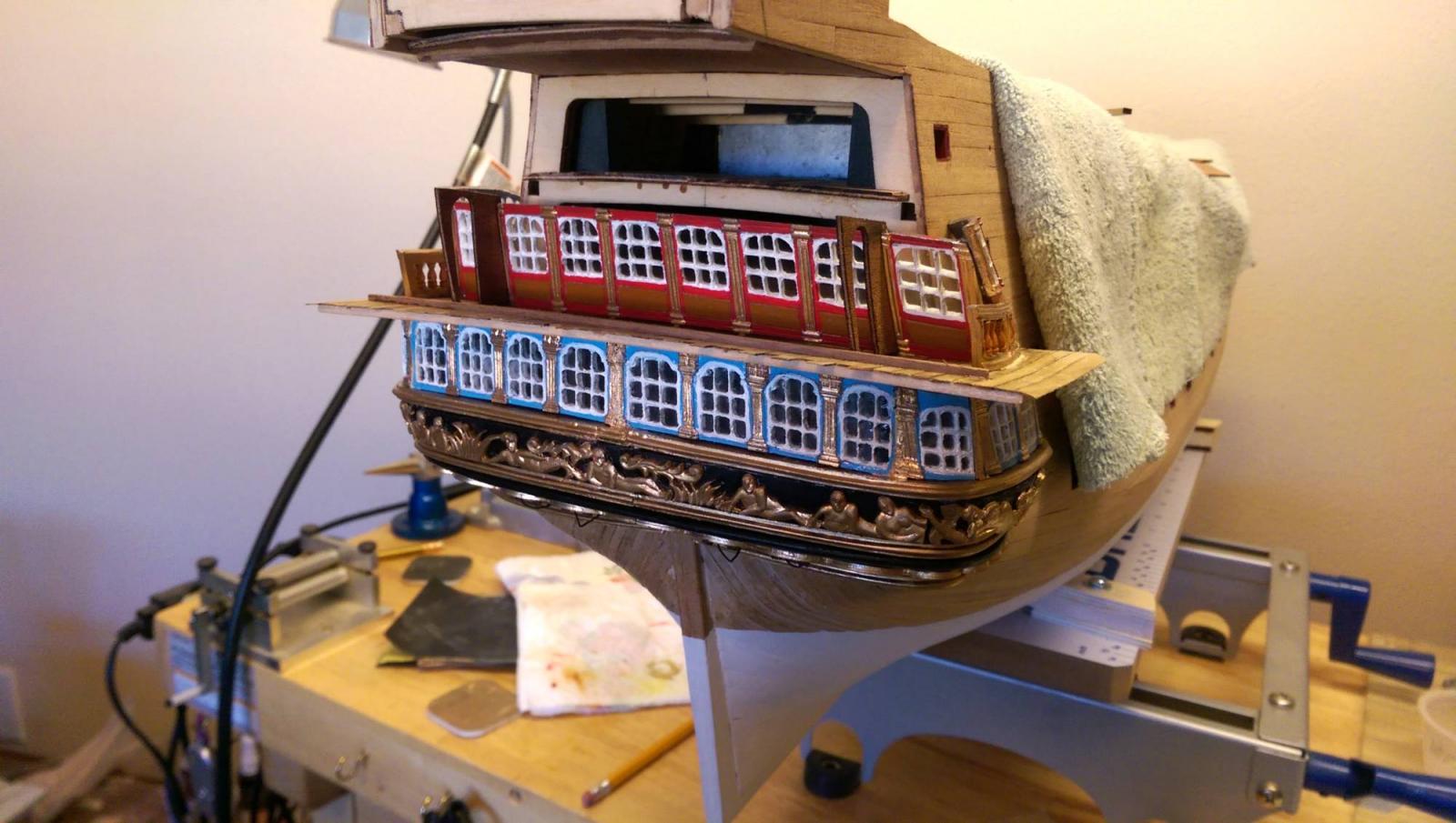
Continuing on with the stern galleries and transom.
1. The upper metal trim piece is placed on the transom base.
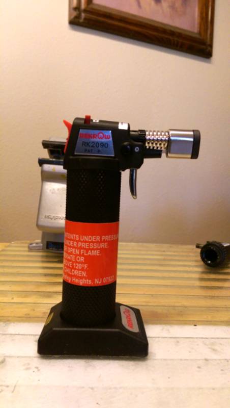
2. The lower gallery windows which consist of 6 pieces are put in place. They had to be bent and contoured considerably using a butane torch. A number of backing plates made up of scrap wood were glued to the base and painted black. These are needed to support the metal window pieces. There were some gaps in the window pieces which had to be filled in with a filler.
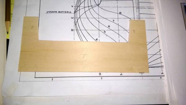
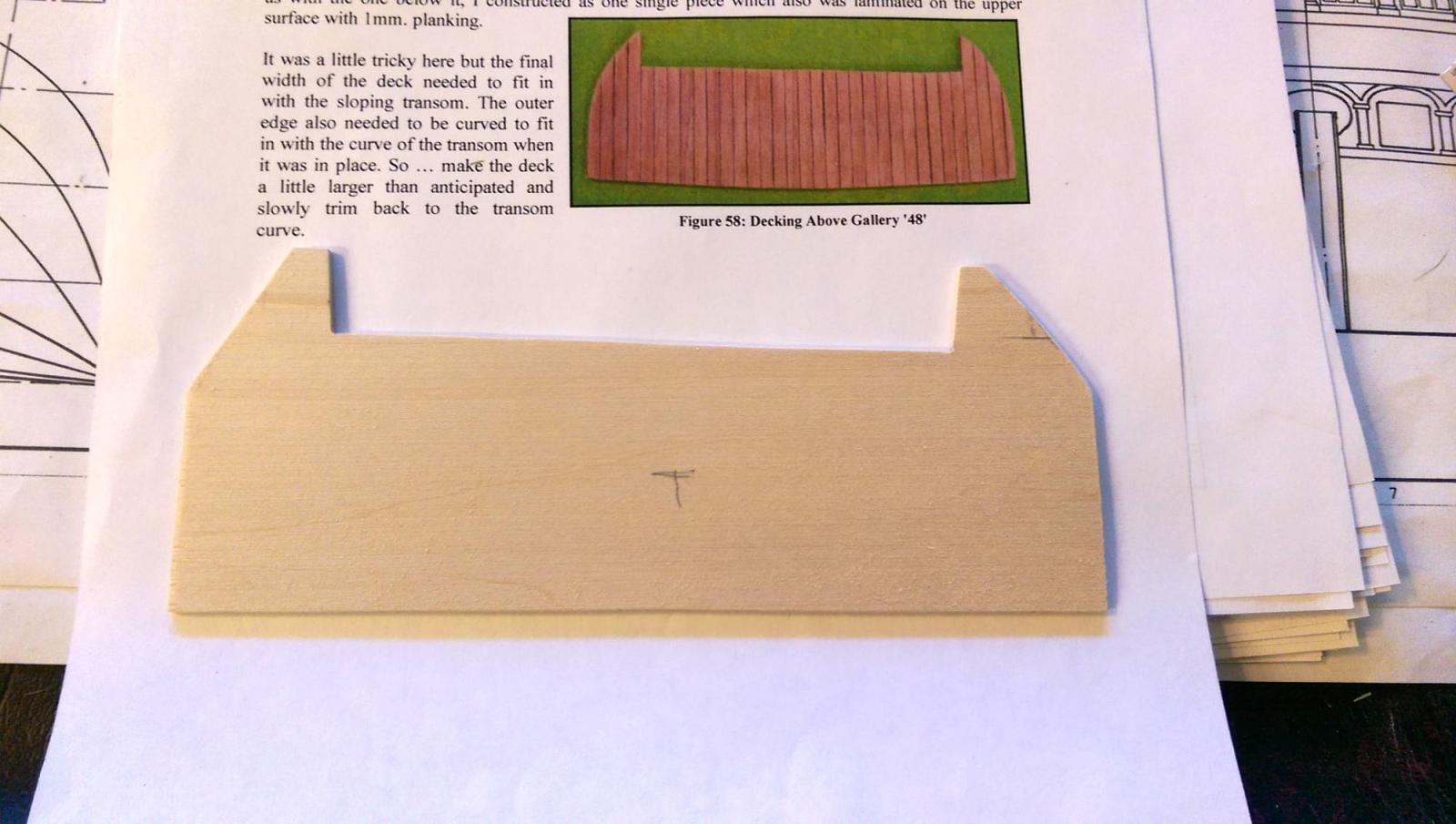
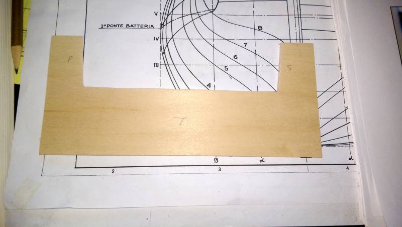
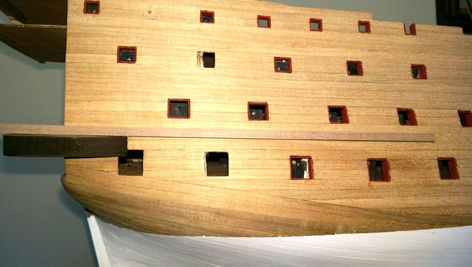
3. The extended deck which mounts on top of the lower gallery windows was made from a sheet of 3/32" x 4" x 24" basswood (not included). The width from the frame 8 to the deck end needs to be 48mm to allow enough overhang from the windows to support the transom back and also the stanchion railing. Once placed permantely, it will be cut to match the contour of the stern galleries. It will also then be planked on top with deck planking strips.

-
-
I am bending many of the metal castings and some require severe curving. To prevent breakage, I use a butane torch. I heat the metal to just hot enough that you can't touch it, so it doesn't melt. Then use an anvil and tiny hammer to gently tap the metal. It bends easily and does not break.
Vince P.

- mtaylor, Mirabell61 and GLakie
-
3
-
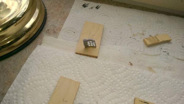
Just learned another lesson the hard way.
As you know, I cut out the tiny window panes in the metal gallery castings and filled them in with a liquid window glaze. They came out very nice and look like real glass. I then glued the castings in place using very little CA glue. It seems the fumes from the glue turned most all of the nice panes white. It took about a day for the white to show up.  . I had to remove the castings and scrape out the windows and do it again. Now I have to figure out what glue to use that won't fog up the windows and still be strong enough. I don't think PVA glue will hold metal very well.
Vince P.
-
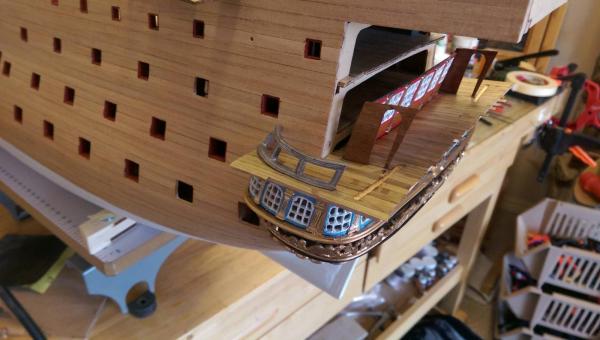
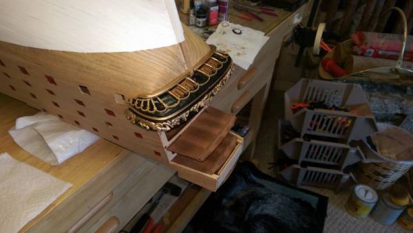
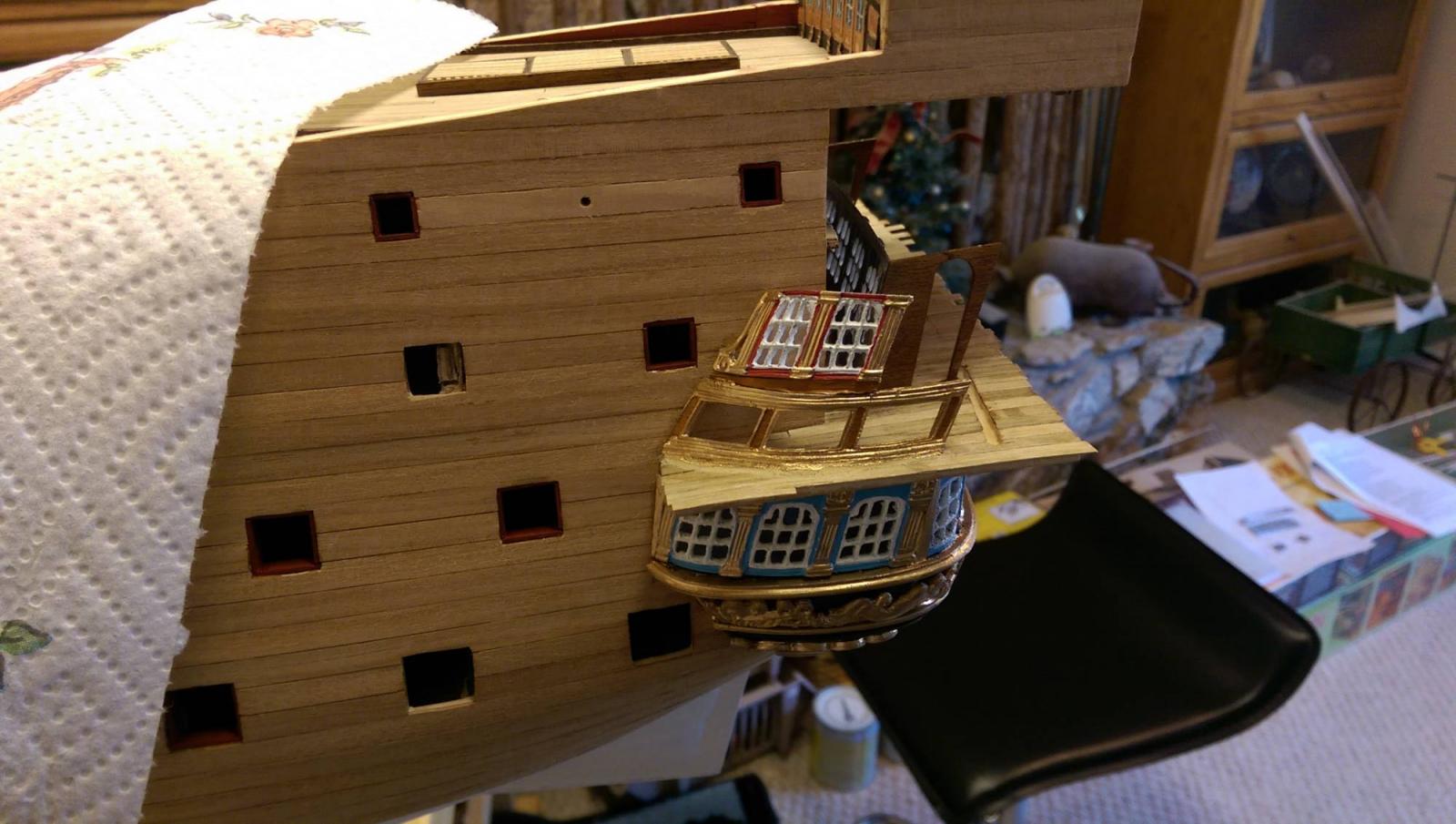
I am still working on the transom base.
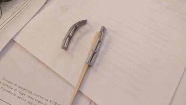
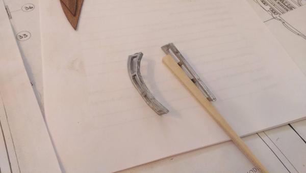
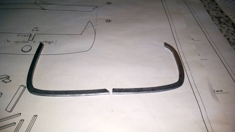
The base has been mounted on the hull with all of the decorative pieces except for the top rail. It will be placed once I flip the hull over. The last photo shows how much the metal trim has to be shaped. The piece on the left is before and on the right is after. The metal is hard to bend without breaking and requires a little heating to make it softer. I used a plastic hammer and an anvil to make the bends.
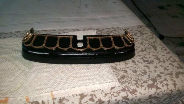
There are 4 gunports in the transom base. The lids had to be made from scratch and were placed along with the hinges and pull ropes.
Vince P.
-
-
Since interest has been shown in this tool by many including myself, here goes a hopefully, full review. I will preface this by saying that this tool is NOT for everyone. To make it clear: if you are expecting out-of-box performance from this, stop reading and go do something else. I fear this is going to be rather long winded....
Background
My scroll saw skills leave a lot to be desired and for repetitive items like knees, beams and even cutting small pieces for carving is an issue. So rather than stand in front of a scroll saw for hours and end up tossing 30-50% of the pieces into the scrap box, I thought about a laser cutter. The so-called “hobby lasers” seem appealing. Reasonably low power requirements, low costs, and relatively smaller size appeals to me.
Research
The caveats that I read about Laser Cutters and followed in the research are:
- Use a company in the country you are in or will provide support to you.
- Use a company that has been in business for more than a couple of years.
I’ve looked at the imported China Lasers (~$500 US) but have found much wrong with them in the reviews. Extra costs of dealing with an import agent to get the unit out of customs and shipped to you, generally mediocre quality in the assembly, and then there’s the normal software that comes with the these products. Also dealing with a seller in China leaves you high and dry without support. I discovered two being “used” here locally. One is not working and hasn’t from the time he got it a few months ago. He’s in the process of replacing the PC board to be compatible with better software and fixing some damaged items like a broken laser tube. The other, I saw it work, and tried my hand but the software (MoshiDraw) is incredibly bad. The owner was running it on an XP PC as it wouldn’t run consistently in Win7 even in compatibility mode.
I looked at another higher priced unit (~$4000 US base price with accessories adding up rapidly). The unit was high quality, made in the US with some Chinese parts including the main board. It used LaserDraw software and from what I saw, the performance was adequate. But as I was unable to sit down and try the woods we use, I can’t give a full report on it. The owners use basswood and thin veneers for creating dollhouses, model railway buildings, etc. The output seemed of good quality but again, it was not the woods or sizes we use. My observation is that this is basically a hobby machine upgraded to being a production type.
The one I’m testing is the Micro-Mark brand (~$2000 US). It comes with a 30 day refund guarantee which, if I determine this isn’t what will work for me, I’ll return it. I read their claims that this machine is built to their specifications (http://www.micromark.com/html_pages/misc/the-micro-mark-difference.pdf) . I know that some of us (myself included) have issues with certain practices which I won’t go into. I will say that I won’t buy ripped off equipment. This unit doesn’t appear ripped off but an upgraded Chinese unit.
I did not consider anything more powerful than 40W. Maybe I should have, but there's also a cost factor that goes with that.
Pre-Order
The unit uses CorelLaser as its cutting software using an industry standard HP Plotter Driver and also Corel Draw. I downloaded the manual and documentation from MM. I also ordered a copy of CorelDraw X6 from Amazon. CorelLaser works only with CorelDraw above version 13 so I bought a shrink wrapped, new-in-the-box program for $150 US. I would suggest you do your homework on this. X7, the latest from Corel is a subscription based program. In other words, you pay every month for it. I prefer to have a CD in my drawer just in case….
I spent a week or so refreshing myself on CorelDraw as the last time I used it was Version 5… yeah… been a few years.
Unpacking and Set-Up
I received this is 3 boxes, well packed in foam. Unpacking is pretty straight forward. I would suggest that the air pump and water pump NOT be removed from their bubble wrap as there is nothing on these items to indicate what they are. I wish that MM had put a photo or two in the instruction manual to identify parts.
One thing that is needed is a GFI socket. I’m using a GFI adapter in case I wish at some future date, to move the cutter to a different place.
Set-up is pretty straight forward following the manual. The hardest part was figuring out the exhaust setup without cutting a hole in the wall of the house. Also, do NOT secure the exhaust unit to the cutter with tape. Use #10 X 3/4” self-tapping screws. There’s bit a misfit between these parts and the tape will not hold it securely in place.
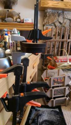
Here's photos of the unit and all the accessories...
 Laser Cutter.JPGControl Panel.JPGElectronics Compartment.JPGLaser Tube.JPGBackside.JPGWater Pump and GFI Adapter.JPG
Testing Started
I used the factory settings and followed the instructions in the manual for the recommended passes and power. Not a happy camper using boxwood. The little nameplate is 1/8” thick boxwood. Took 9 passes to cut. Lots of charring.
test cuts.JPGtest cut - nameplate 1.JPGI discovered the mirrors were off. MM instructions are vague in the extreme and need some serious re-writing to be useful. I Googled and eventually found the information I needed here: http://dck40.blogspot.com/
Using other web sources, I discovered that the lens in the cutting head was upside down… WTF!!!! This really irritated me.
After spending a day going back and forth between all three mirrors and adjusting them, and then resetting the focus for the wood, here’s the next round.
test cut - nameplate2.JPG anchor stocks.JPGI’m continuing to test and massage things. This will take time. I’m able to cut 3/16” boxwwod which requires multiple passes but as yet, not I’ve not tried ¼” boxwood.
Overall Observations.
The learning curve on this machine is a vertical, straight line. These machines are still in their infancy and not mature. Documentation is extremely sparse although there are forums out there for laser cutters, getting to the information you need for a particular type or model is a bit overwhelming and I consider myself a knowledgeable Googler.
There is no guidance on power settings or cutting speed to cut various types and thicknesses of wood. Serious experimentation is required.
This machine is finicky in that all mirrors have to be perfectly adjusted to make use of the power and they have to be kept clean. It is big, and sometimes smelly. It’s not a production machine and the bucket of cooling water will have to be watched. Running at “high” power (no definition from anyone on this or on the max water temperature) will shorten the life of the laser bulb. There is a focus issue and I believe it could cut with a thinner kerf. I’m trying to talk with MM about this….
The nameplate, I couldn’t even begin to cut something that tiny on the scroll saw. It’s now almost ready for carving. I do need to tweak the drawing some more to get a bit better spacing. The anchor stocks I’ve done, would have taken maybe 30 minutes on the scroll saw. Including drawing time, this took approximately 1 hour and no wasted/ruined pieces. However, all 4 are exactly alike and the bolt holes are ready to be cleaned of char and the bolts installed. No fiddling with the drill press, either. I have about 8 other parts ready for cutting and will do them as I go. The kerf size and charring are still an issue.
I’ll say it again, it’s not for everyone. If you have the time and ability to Google and research and then to fiddle with it and get it running correctly and then to keep it running, it might be ok for you. The manuals are skimpy at best and a bit of creative Googling will need to be done to help sort things out. There’s still settings in CorelLaser that I have no idea what they do. There is an alternative to CorelLaser called LaserCut 5.3. I haven’t tried it yet and the documentation on-line seems rather sparse from what I’ve seen.
Thicknesses of 3/16” and up are tricky to work with. There’s no tables or inputs from MM on this and the web is all over the place on using these “hobby” cutters. However, most folks who have reviewed similar machines are using basswood and thin woods. Doll houses and RR accessories seem to be the major uses along with etching for various things like signs, pendants, etc. I need to have a conversation with MM on the lens… I think it needs to be higher quality and damn it... there’s no excuse to have it installed upside down.
Lastly, tech support. I emailed them late on a Sunday night about some issues. I'm still waiting for answer after 3 days…
Since we’re talking tech support, it’s worthwhile to note that tech support hours are very limited… Monday through Friday, from 1:00 pm to 5:00 pm, EDT.
I asked tech support before I ordered about using an extender cable and the answer was a simple: not recommended. The unit comes with a 9 foot USB cable so I had to seriously rearrange my workshop to get it closer to the computer. I’m testing a USB powered extender cable so I don’t have cabling running across the floor where it can be stepped on. Jury is out on this.
The short answer for all this is: I wouldn’t recommend it unless you are tech savvy, not just with computers but also can tolerate a large learning curve. The quality of the cuts could be a lot better. Overall, it might better that if this tool is something you have to have then spend about double the cash and get a higher powered, non-China built laser cutter with some tech support. The BossLaser that Chuck uses runs about $5000 and has the higher power to cut thicker woods and is, I believe, also suitable as a production machine.
I'll continue to test, adjust, fiddle, and tweak for now...
Thanks Mark, for your feedback. It is appreciated that you put all this work into keeping us posted.
Vince P.
-
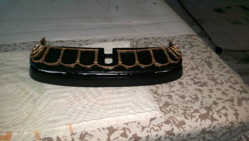
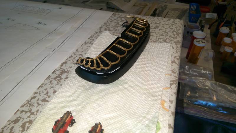
The transom base pieces have been fully carved and the channel cut for the metal trim. A hole has been cut for the rudder post and the whole thing painted black. Two pieces of the decorative metal have been placed. The metal is painted gold and then bent to conform to the wood base. The pieces have to be carefully trimmed of extra metal. The metal is very fragile and has to be bent ever so carefully to prevent breakage.
Vince P.

- popeye2sea, mtaylor, maggsl_01 and 7 others
-
10
-
I have started to tackle what I believe will be the most challenging and difficult part of this build. That is construction of the transom and stern galleries.
There are 2 ways to build these. One is using the plan drawings from scratch and the other is using the carved metal trim pieces included with the kit and using the plans for measurement references where necessary. Pete's notes in the Euromodel references cover both and Keith Julier's article deals only with the first choice.
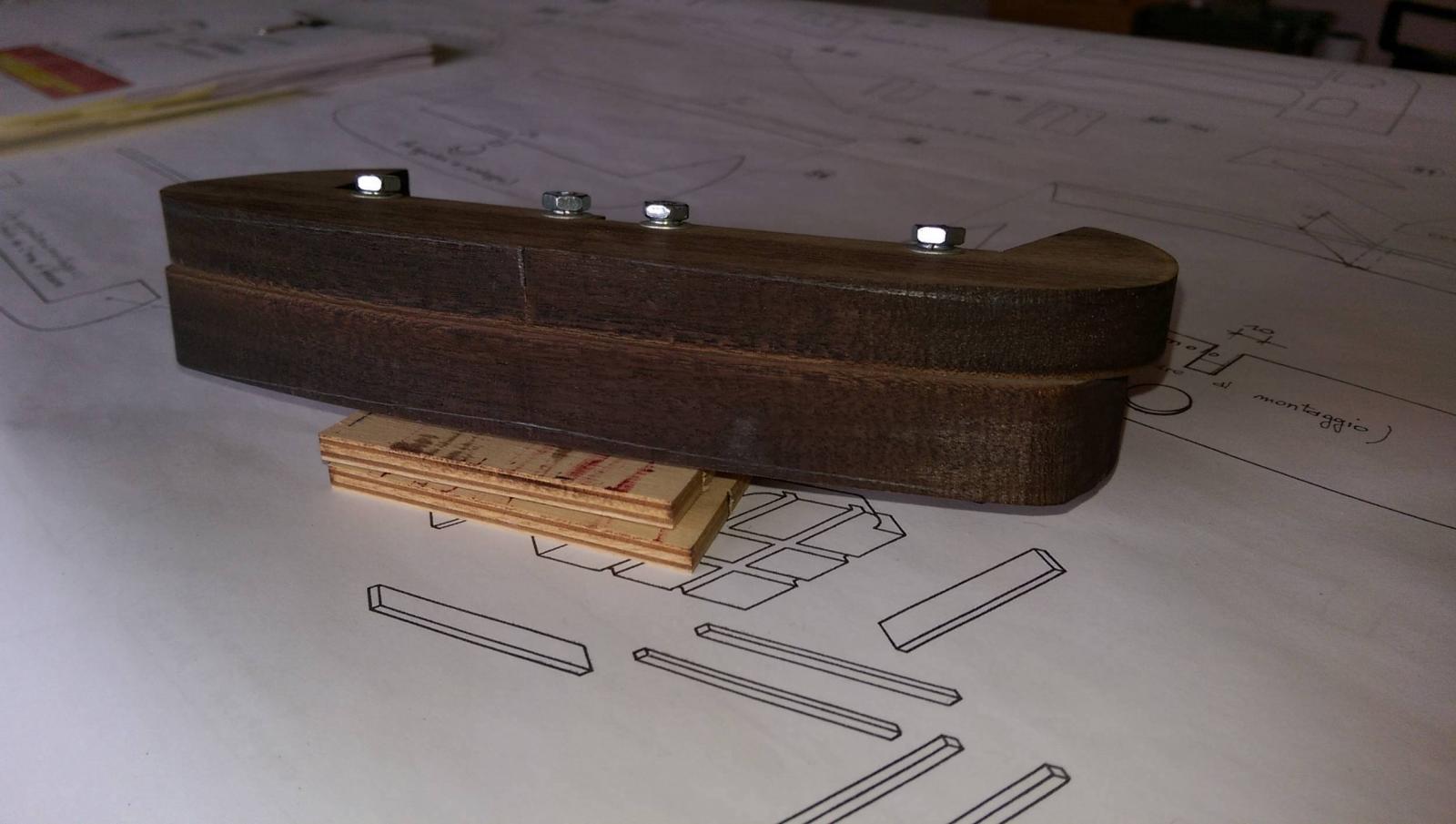
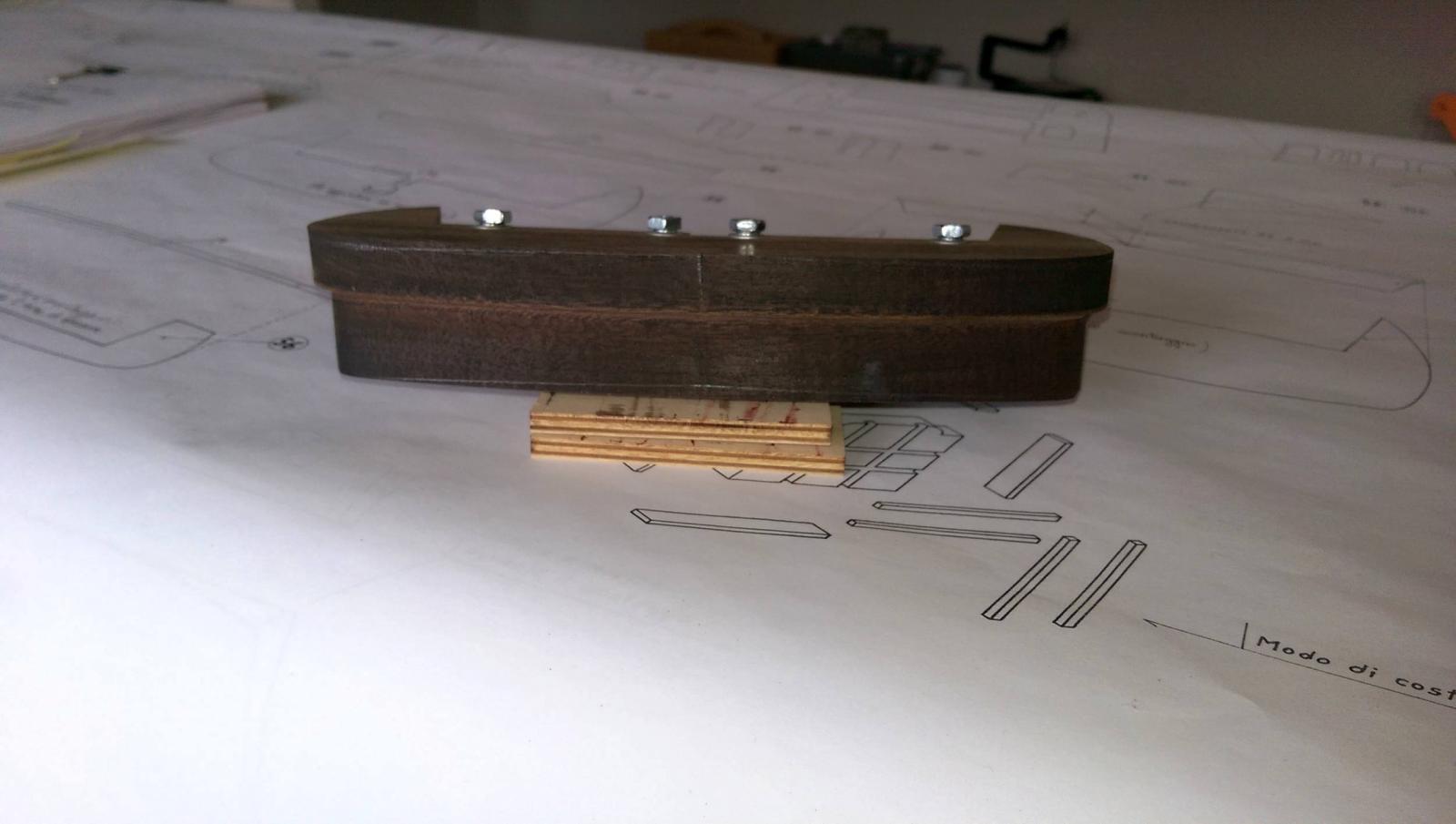
I have decided to use Pete's notes and the second method. There are 3 wood pieces that make up the transom base and they will require a considerable amount of carving in every plane. The parts are #56 which is a thin plywood piece, parts #55 and #54 which are thick walnut pieces. Since I am using the metal carved trim pieces, Part #56 will not be needed on the ship, but must be used to mark the edge of the bottom of piece #55 for carving.
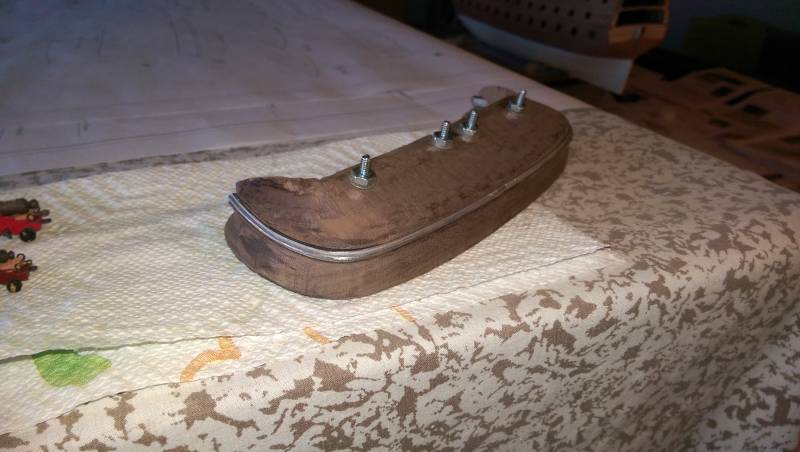
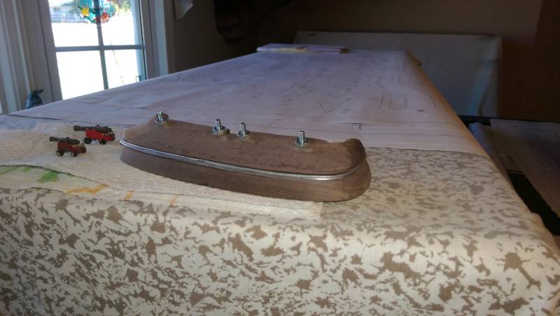
The first thing to do is temporarily join all 3 pieces together with either bolts or dowels so the edges can be marked for trimming. Part #56 on bottom, #55 in middle, and #54 on top. Line up the sternpost slots with a piece of 10mm wood and the forward edges of all the pieces. The first 4 photos show this.
Next up is to seperate the pieces and work on #54 by shaving the top and bottom to form the correct camber. The piece is reduced in thickness from 13.0mm to 10.5mm.
Once that is done, place the piece on the stern and mark where it will be heightwise. The distance from the top of the upper quarterdeck to the top center of #54 should be 98.0mm. The piece should also be slanted downward slightly. There are differences of opinion on what the declining angle should be, but I agree with Pete and the line of the lower gun deck should be in line with the top of #54.
In order to get #54 to butt up against the last bulkhead, a considerable amount of wood has to be cut away on the insides of both ends to match the curve of the hull planks, and the slot for the sternpost has to be deepened as well.
The lower edge of the outside surface has to be carved back using the mark made with the edge of #55 to form the inward cant, and the ends have to be trimmed back and beveled to wrap around the last lower gunport. Both Pete's notes and the plans have good drawings to reference this.
Once the piece is sitting correctly on the stern, mark the edges all around with pencil lines and remove it for later.
Vince P.


Royal William by pirozzi - FINISHED - Euromodels - 1/70
in - Kit build logs for subjects built from 1501 - 1750
Posted
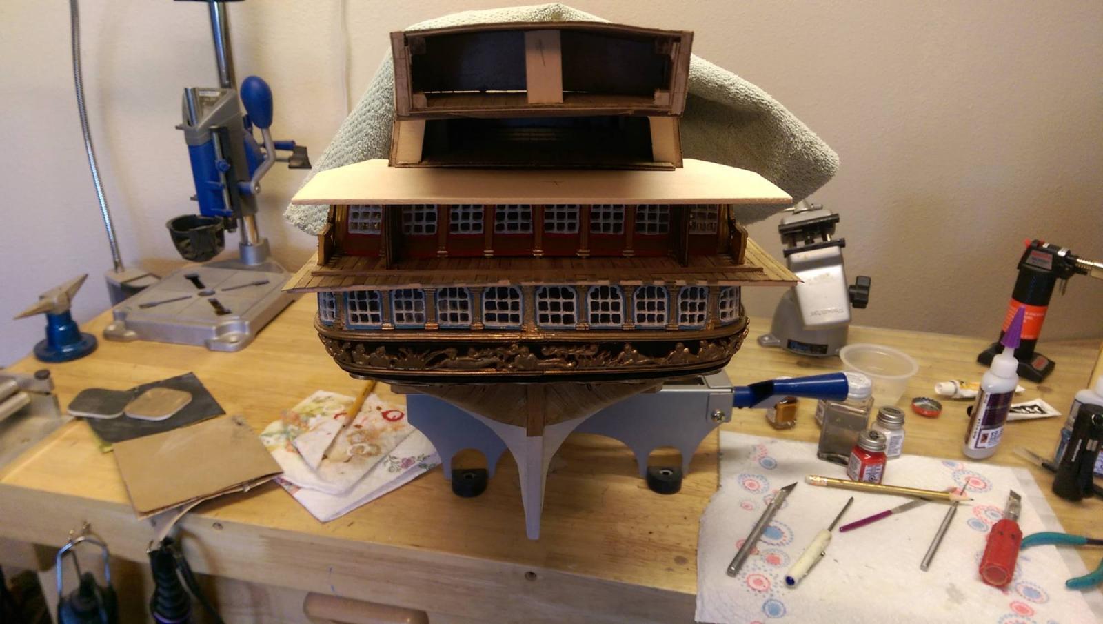
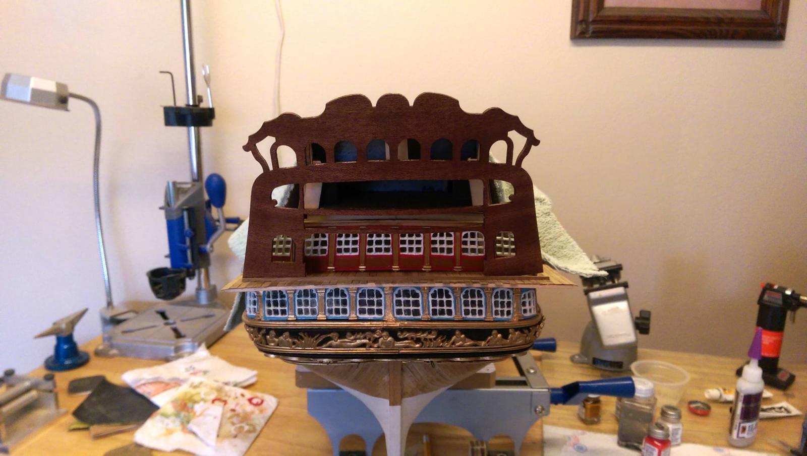
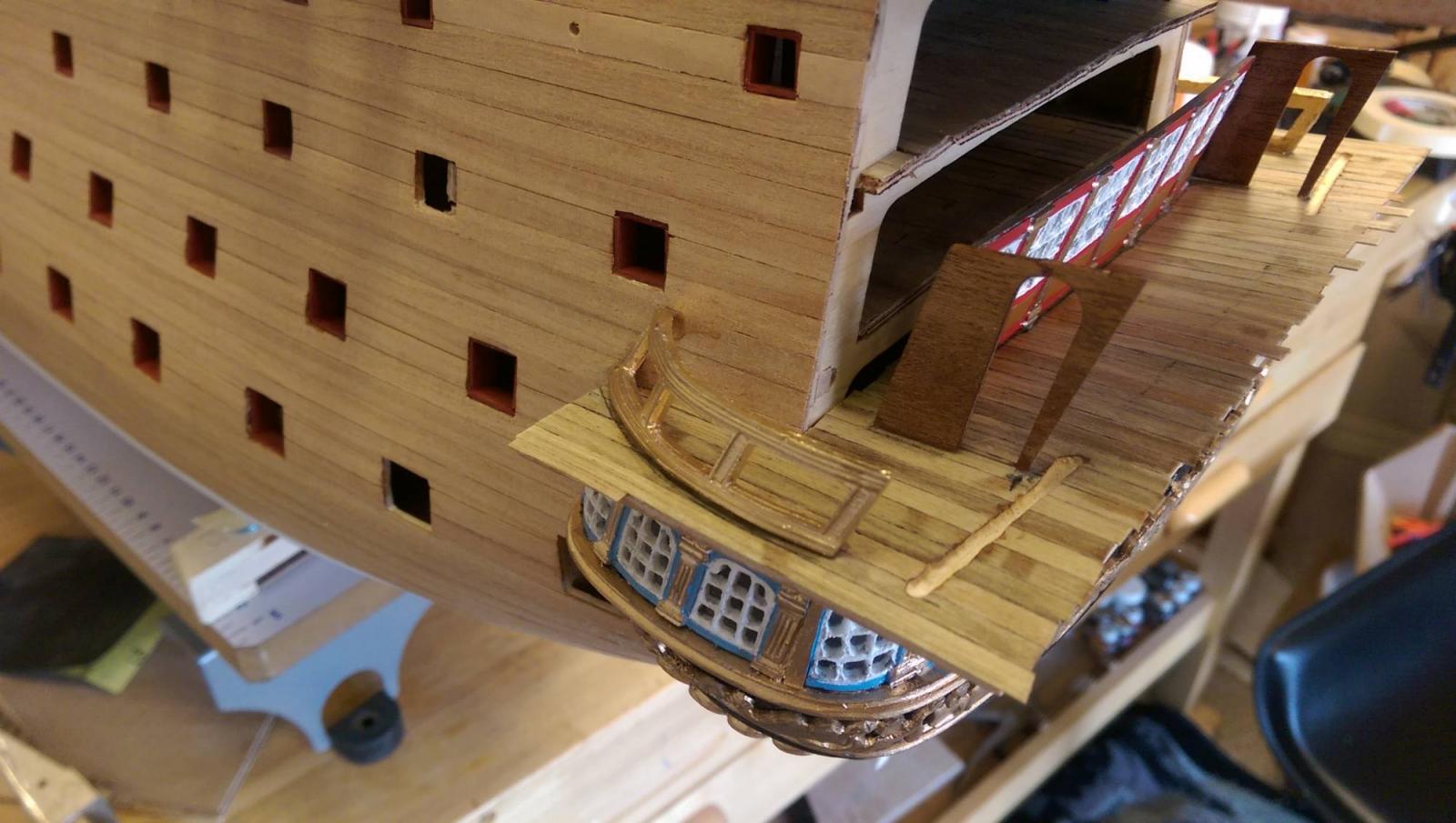
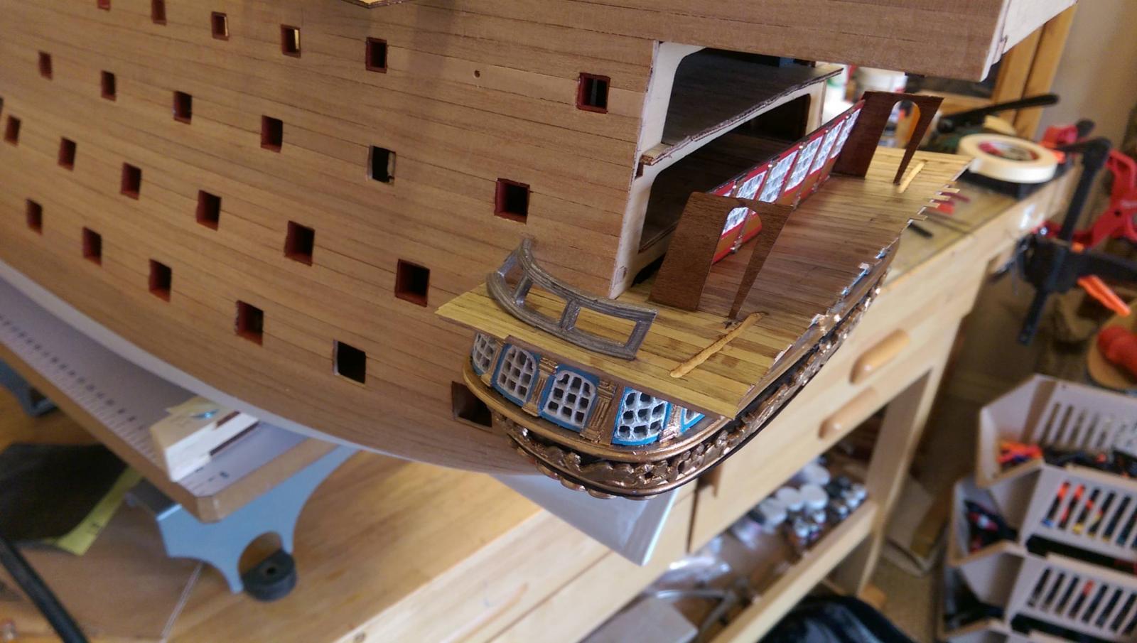
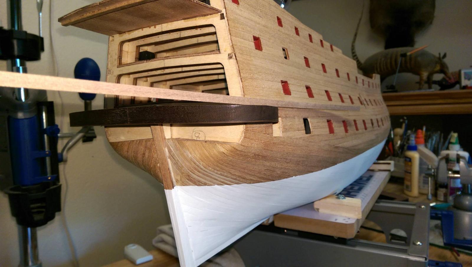
The gallery quarterdeck extension is in place. It will be trimmed and beveled to fit the transom.
Vince P.