
DelF
-
Posts
1,409 -
Joined
-
Last visited
Content Type
Profiles
Forums
Gallery
Events
Everything posted by DelF
-
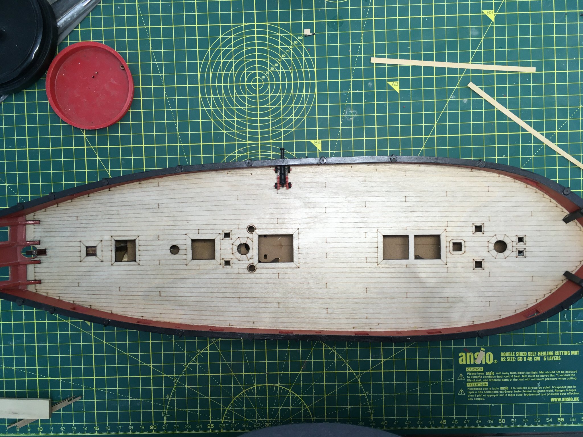
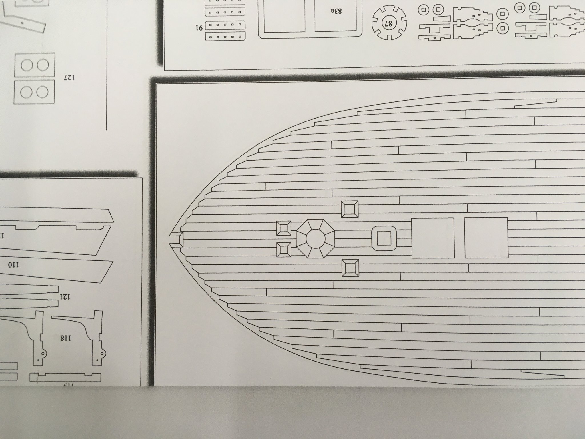
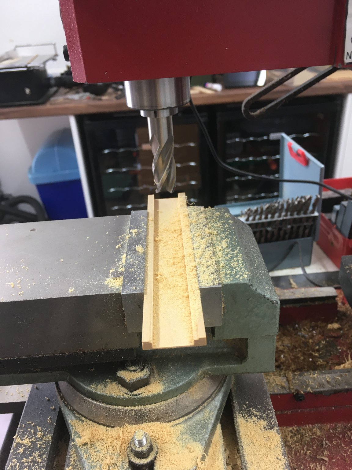
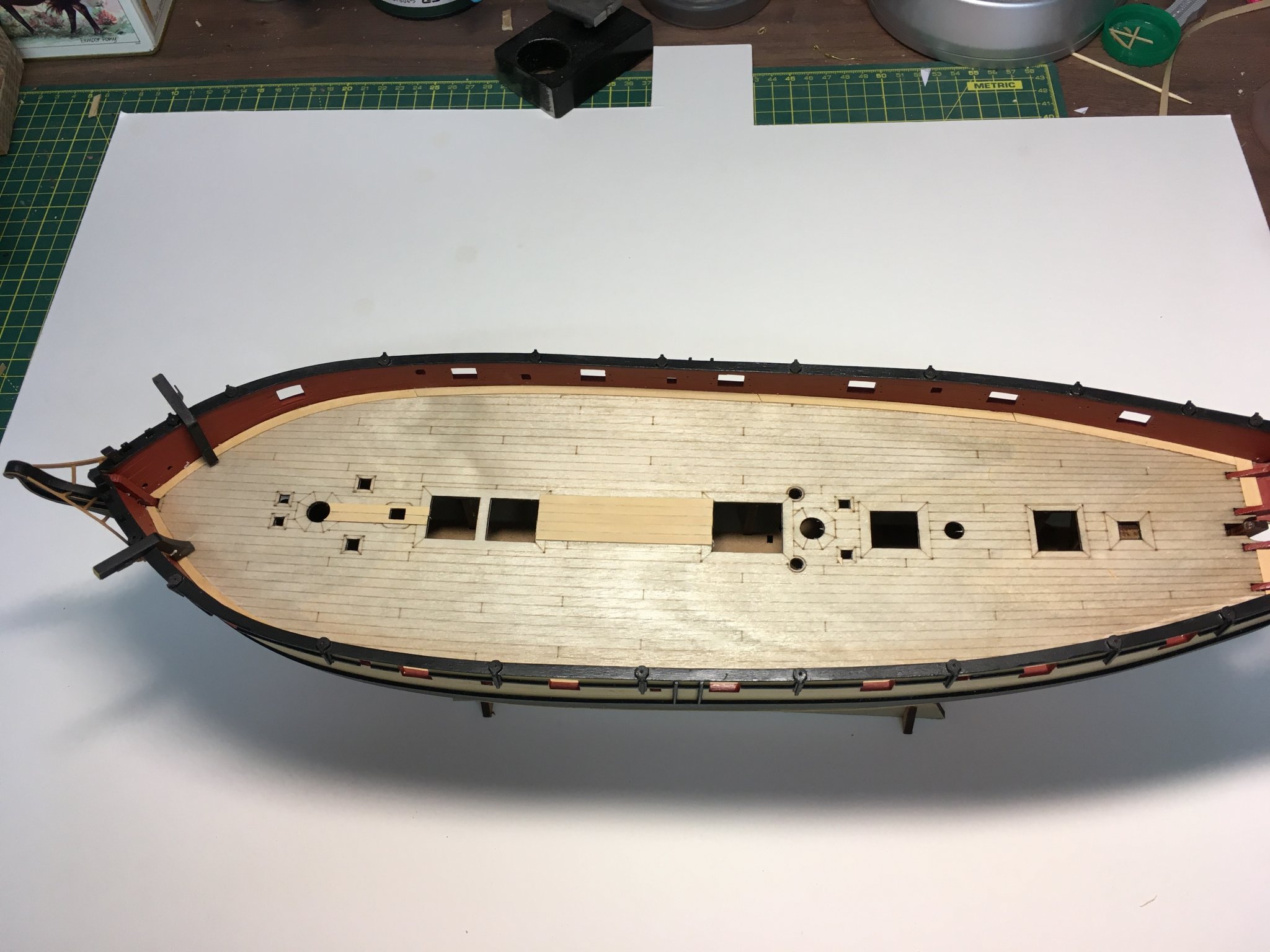
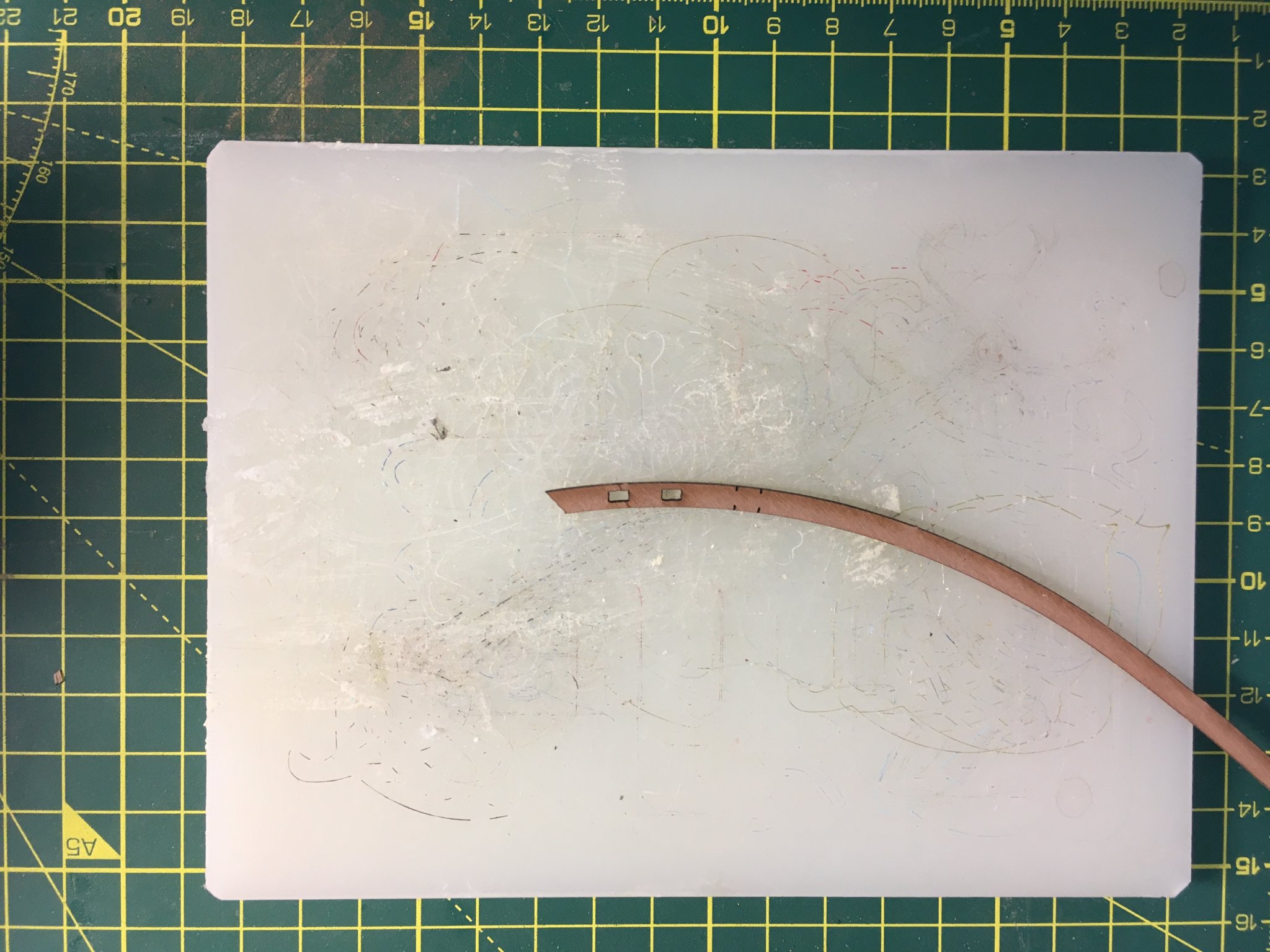
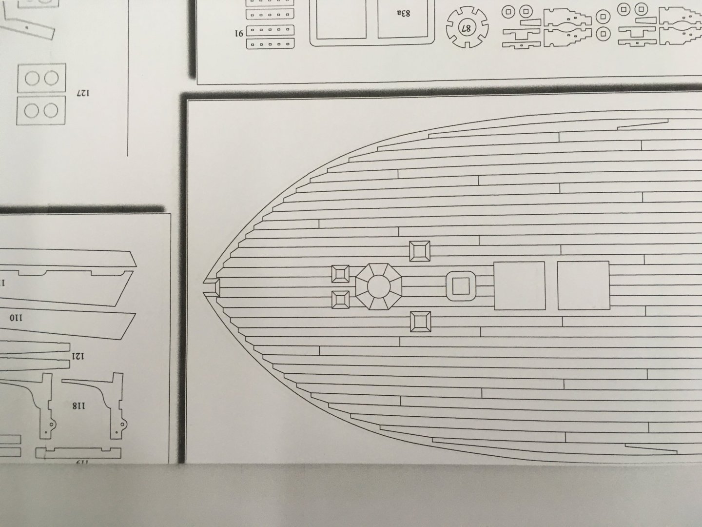
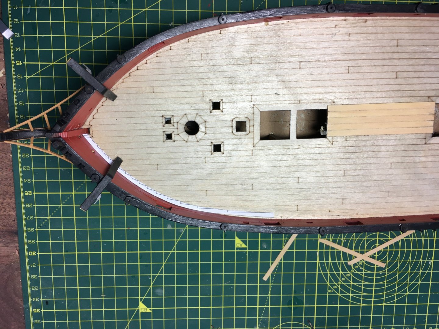
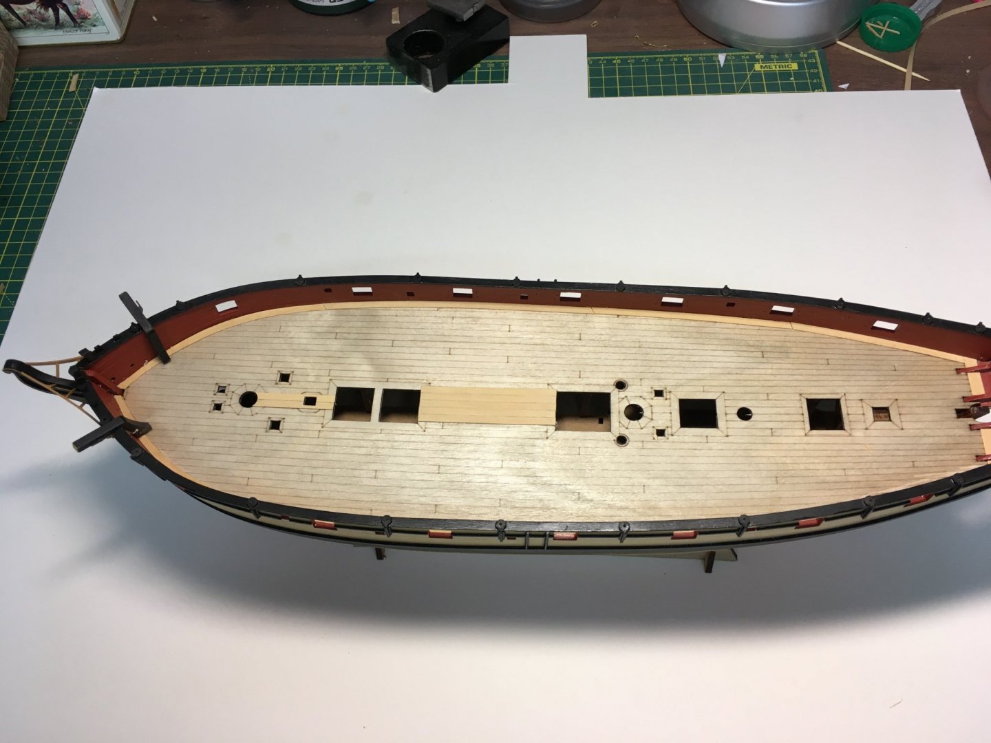
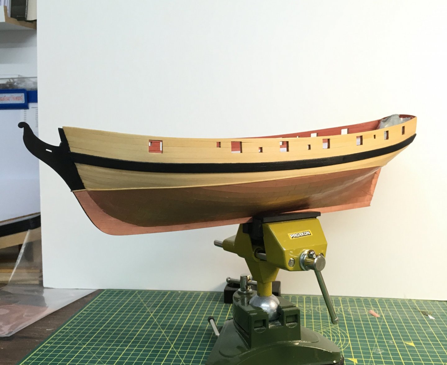
 Thanks as always for the likes and supportive comments. A Diversion I had intended to complete work on the rudder, but when I removed its protective covering I started having second thoughts about the laser etched deck. There are patterns in the surface of the deck that catch the light and give the impression, to my eye, of marks and shadows. I tried a couple of surface treatments - shellac and matte polyurethane varnish, but these both tended to magnify the patterns rather than hide them. I suspect that these patterns stand out more on a clear deck, and would tend to be masked once all the normal fittings are in place. However, after much internal debate I decided to lay my own planking on top. After a couple of experiments I found I could mill planks consistently just under 0.5mm - about 1 inch full size, which shouldn't add appreciably to the thickness of the deck. I also found I could loosen the catheads just enough to slip these planks under them. I started with the margin plank. I knew I wouldn't be able to bend a plank laterally to follow the bulwarks so I had no option but to cut the curved sections from wider sheets of boxwood. The following pictures show the process for one section. Milling the sheet: Photocopying the plan, sticking the margin plank to the boxwood sheet, cutting it out and trying it for size: I've now got all the margin planks in place and I'm starting on the planking proper. This will take some time, as I plan to joggle the planks into the margin planks. I hope I don't end up regretting this decision! Derek

- 725 replies
-
- 8
-

-
- vanguard models
- speedy
- (and 1 more)
-
Me too. Derek
-
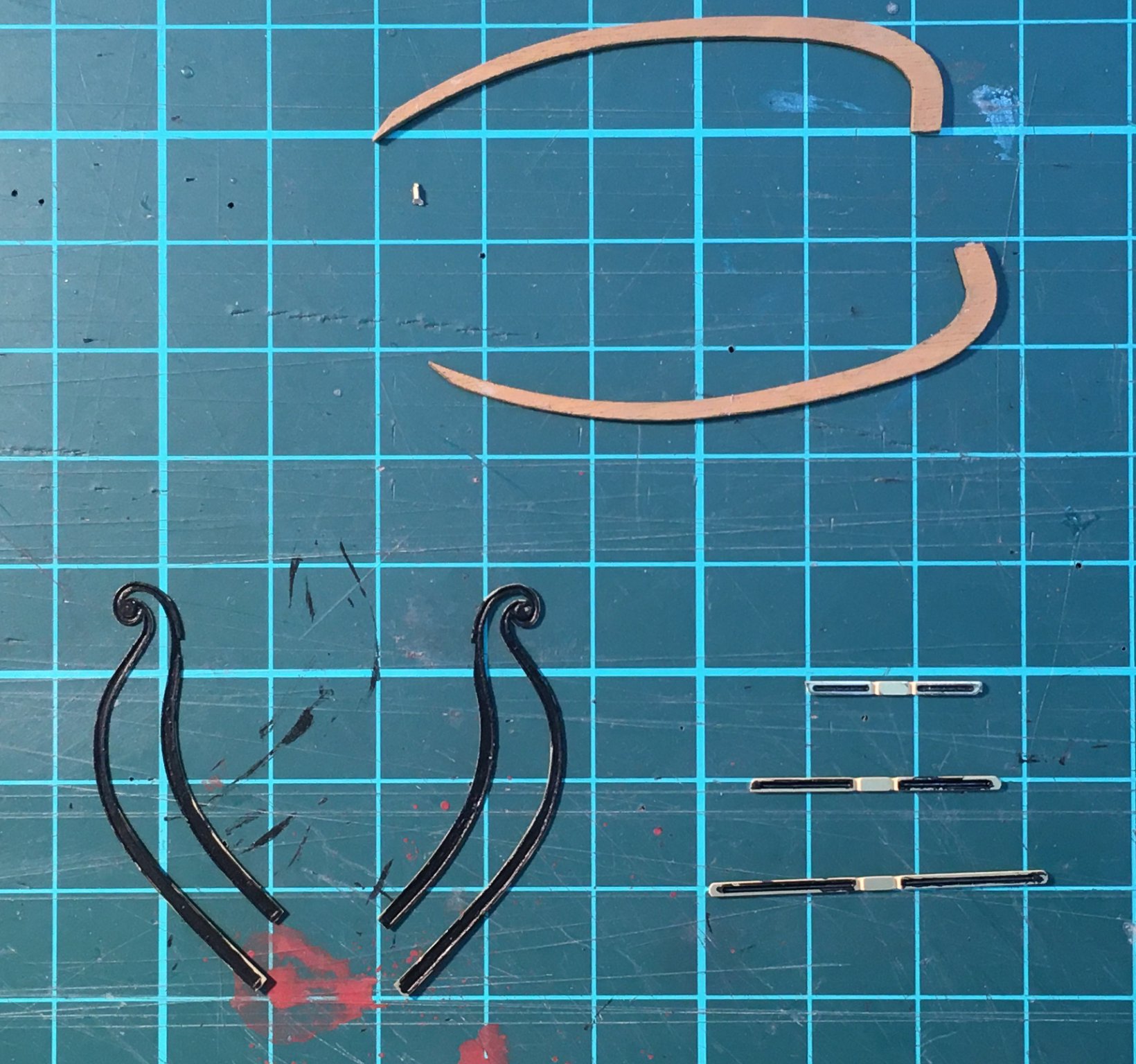
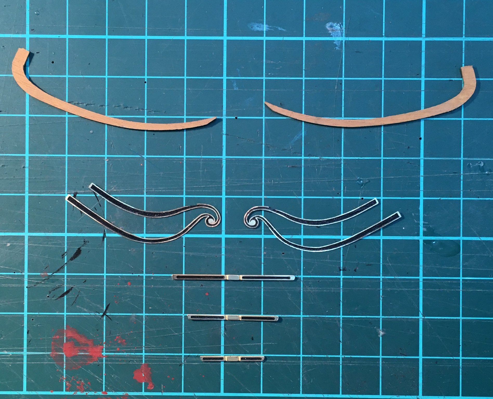
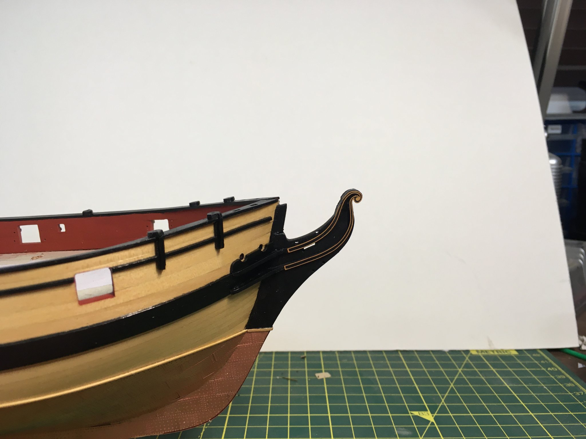
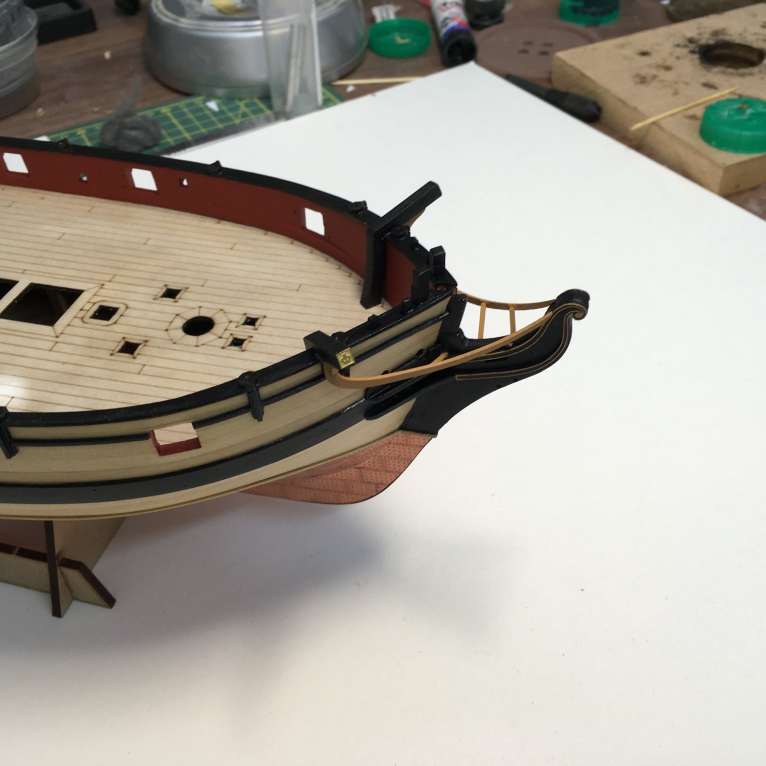
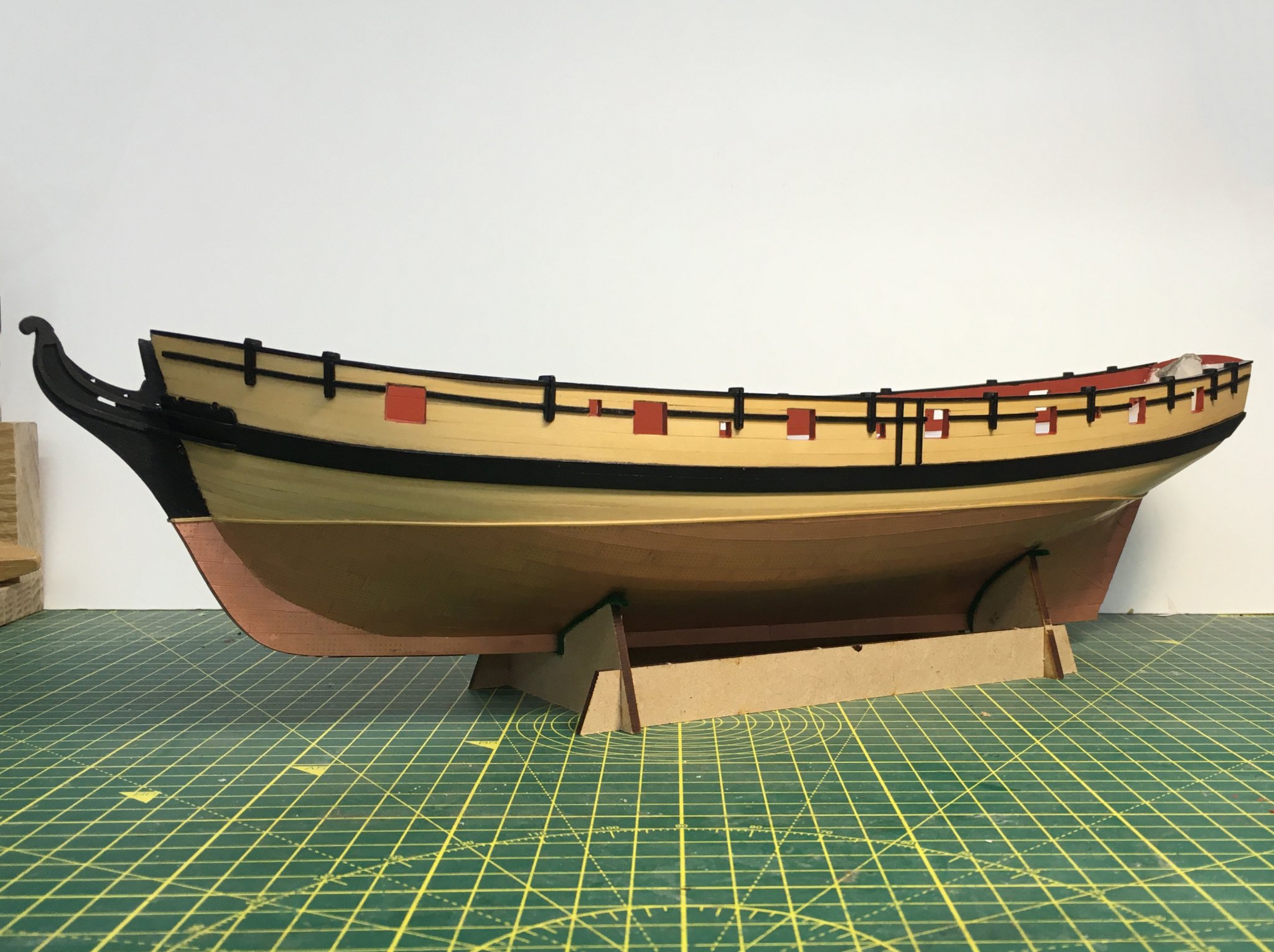
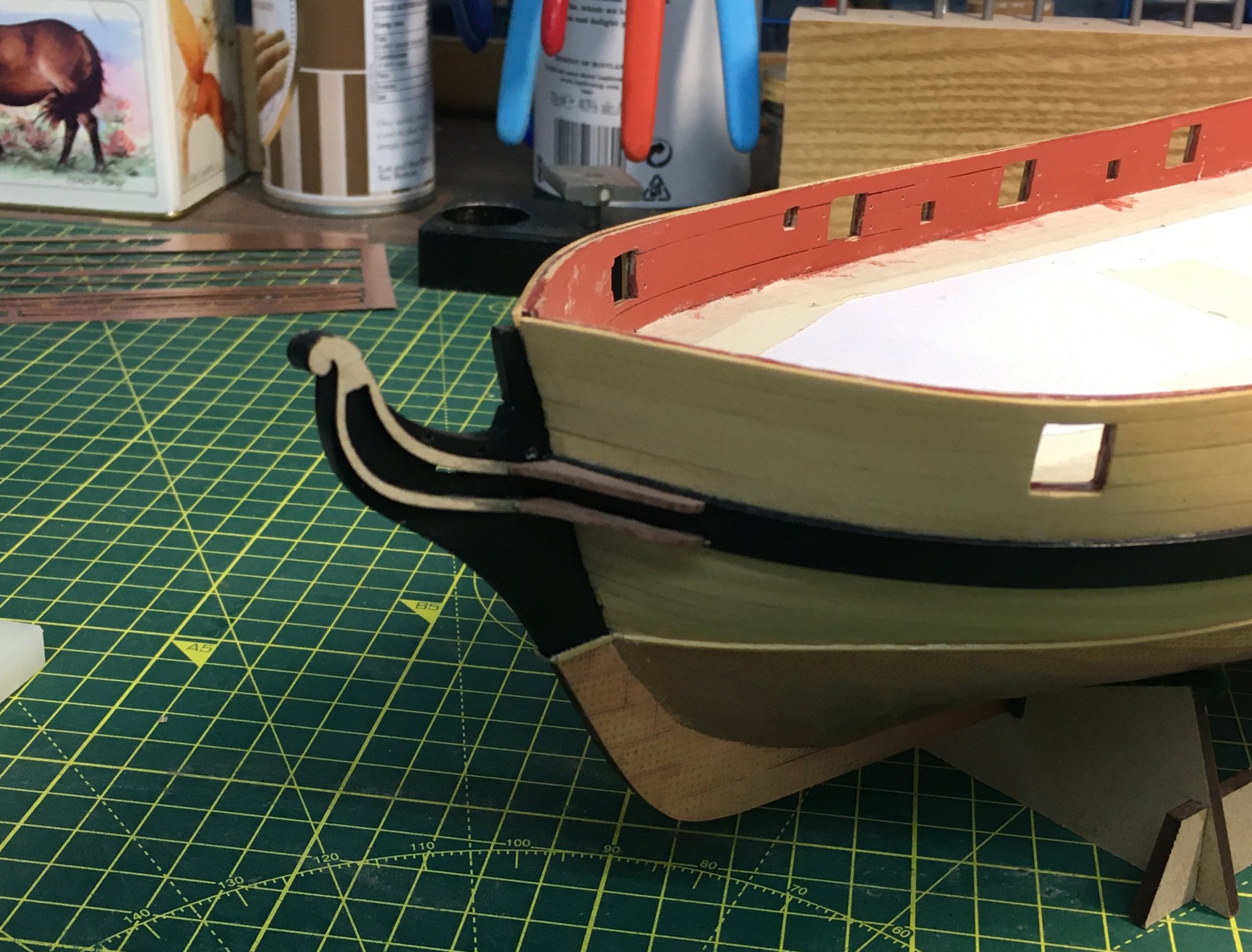
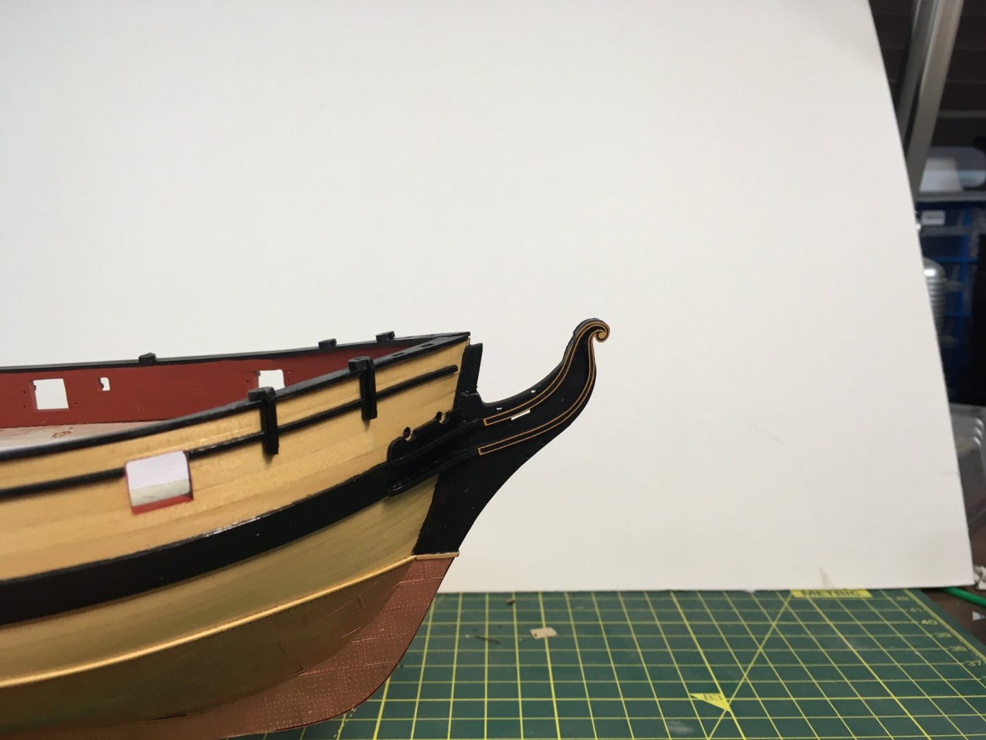
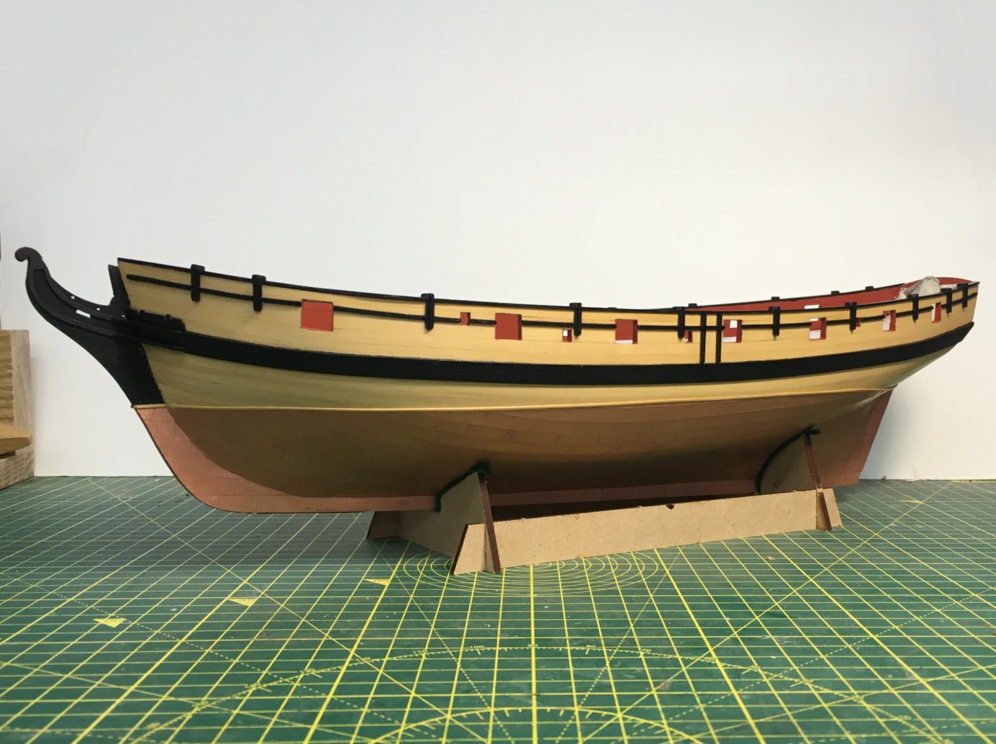
Some fiddly work on the prow, starting with the laser cut bow rails and various photoetch parts for the vertical bow rails and prow decoration. The PE parts are painted yellow ochre, with the recessed central parts painted a contrasting blue or black (I chose black). Chris suggests painting the parts yellow first, but I didn't think I'd be able to do the recessed parts neatly enough and avoid getting black on the yellow, so I did it the other way round - painting the black first, cleaning the raised bits carefully with a fine file, then painting them yellow: The next task was fitting the bow rails, which proved tricky. The main problem was that there were gaps between the bow rails and the vertical rails that are meant to join them to the prow. I decided that this was because the bow rails were too straight. Rather take them off the model I managed to bend them in situ with my trusty hot air gun. I wet the rail with a finger dipped in water, pushed it inwards with the stick and blasted it with hot air until dry. Miraculously it stayed curved enough to touch the vertical rails. In the photo below I've already done the port side. Btw, I'm not pushing on the stick as both hands were busy holding the air gun and my phone! As a minor aside, I think Chris originally intended that the ends of the vertical rails should locate in holes in the bow rails. The PE parts had little lugs on their ends (which I cut off to make them fit), and if you look carefully at the photos in the manual the bow rails have holes. Anyway, that's not how the design ended up and it works fine. Remaining details were relatively straightforward - catheads, knigtheads etc. I departed from the instructions by not painting the crown on the end of the cathead yellow. I figured Cochrane could have afforded a bit of gold leaf so I left the neat little photoetch crown unpainted. Back to the stern next. Derek


- 725 replies
-
- 15
-
-
- vanguard models
- speedy
- (and 1 more)
-
Hi Ernie I also struggled with the gunport pattern. I found it very difficult to bend such a wide strip in two dimensions to get it to fit snuggly against all the frames. In the end I used a small travel iron (the one I use for Chuck's plank edge-bending technique). I describe in my Speedy log (here) how I used the iron to flatten the gunport pattern in situ. Once they're reasonably flat any remaining lumps and bumps will be lost in the planking. Derek
-
Very neat work. I'm glad you're getting on well with the Swiss files - you'll be on commission from Vallorbe soon! Derek P.S. Looking at the last picture, I see you're getting as untidy as me 😁
- 778 replies
-
- 4
-
-
- cheerful
- Syren Ship Model Company
- (and 1 more)
-
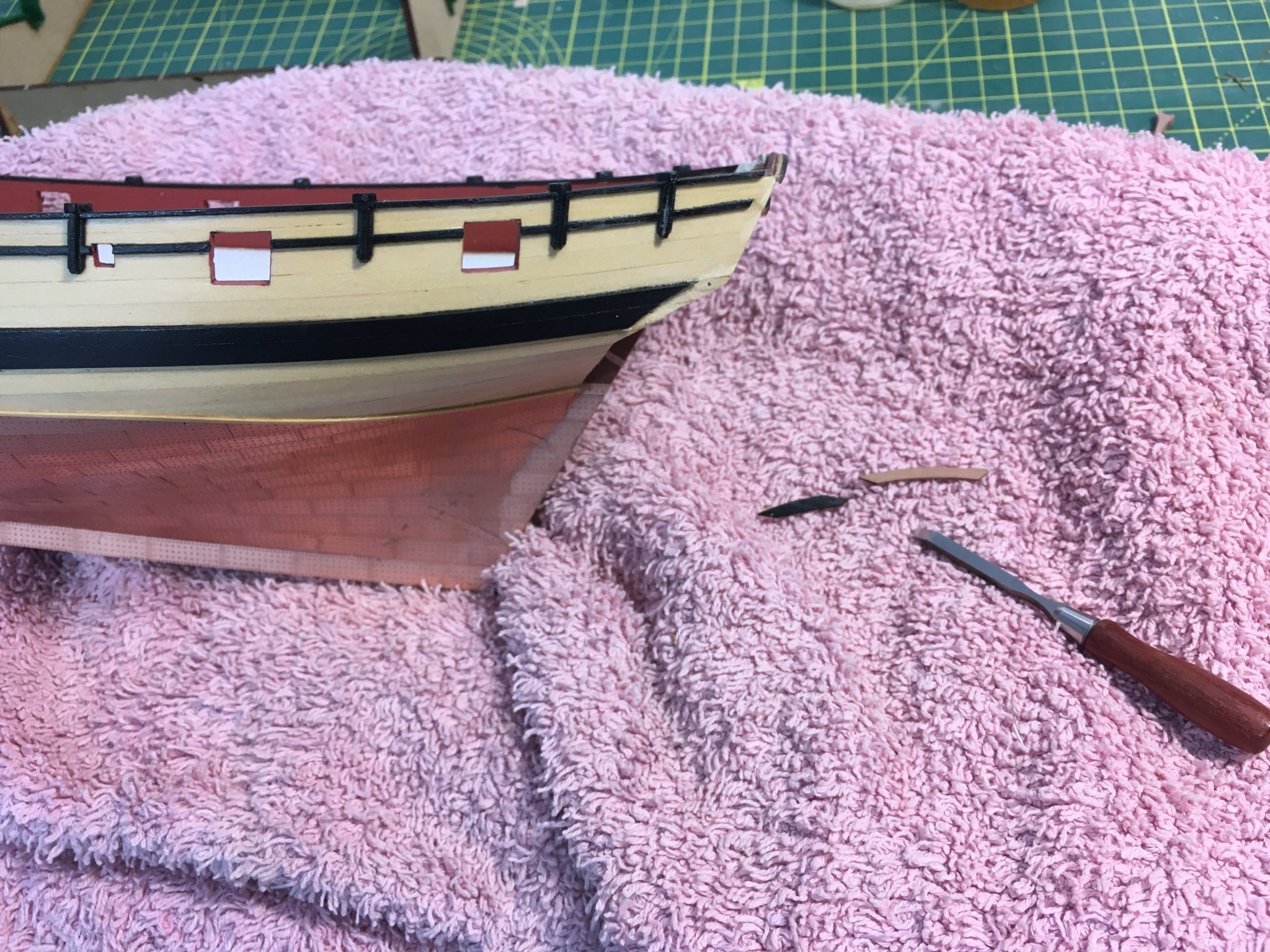
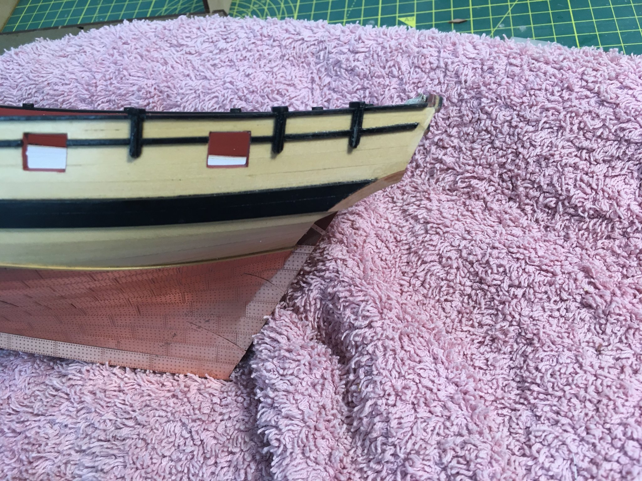
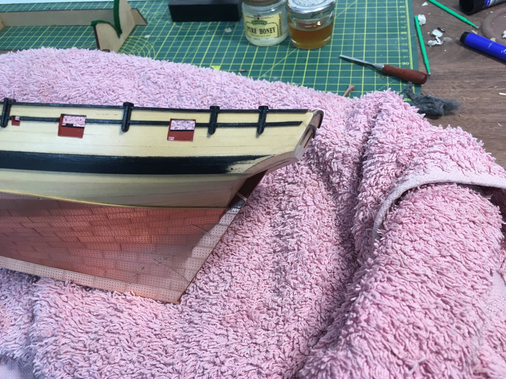
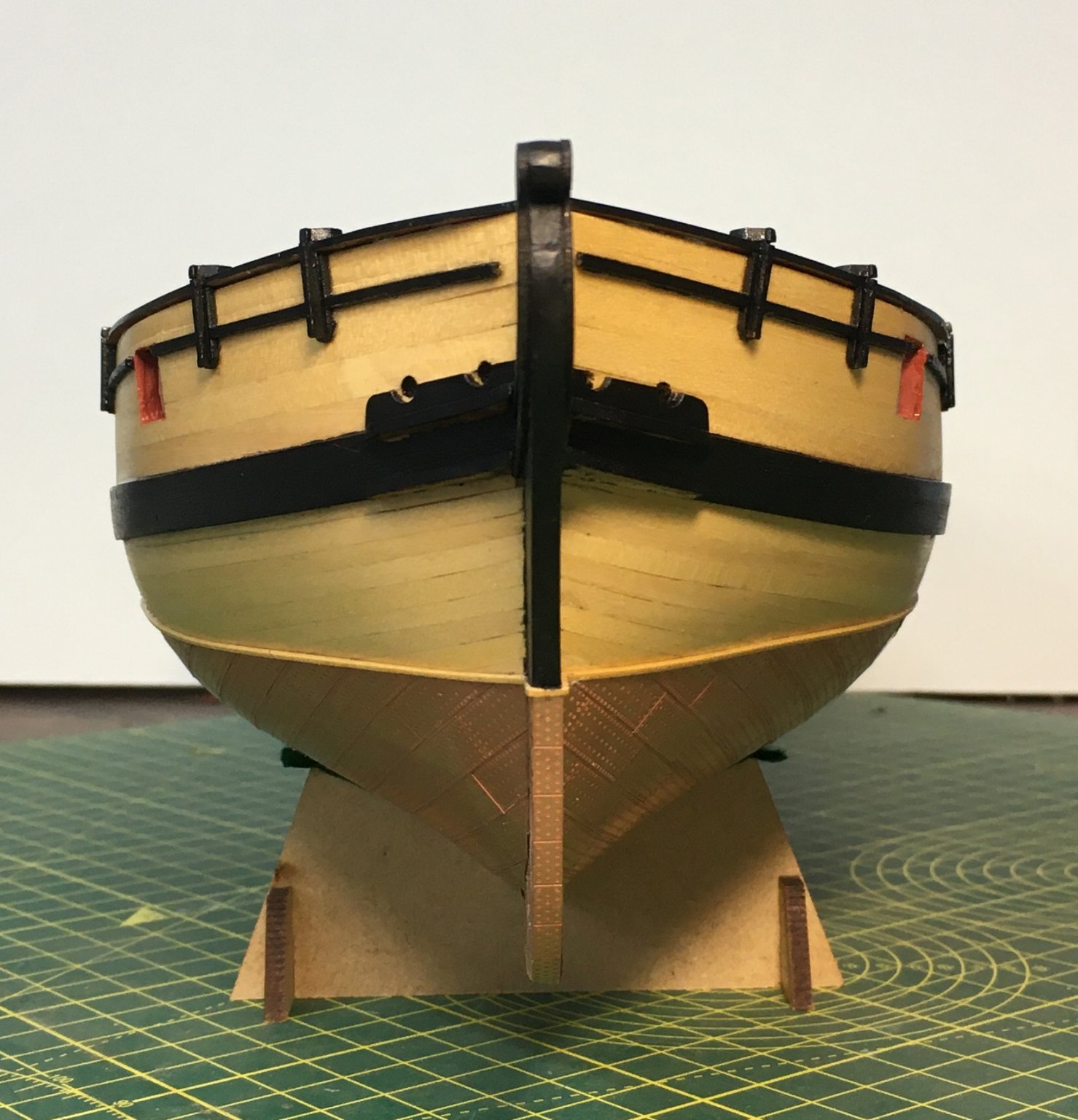
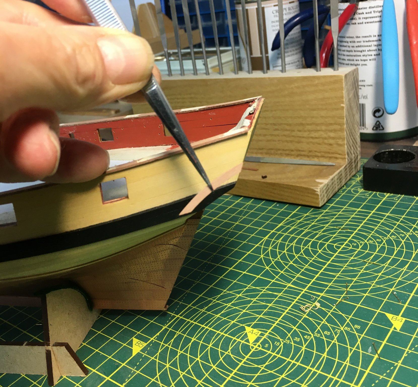
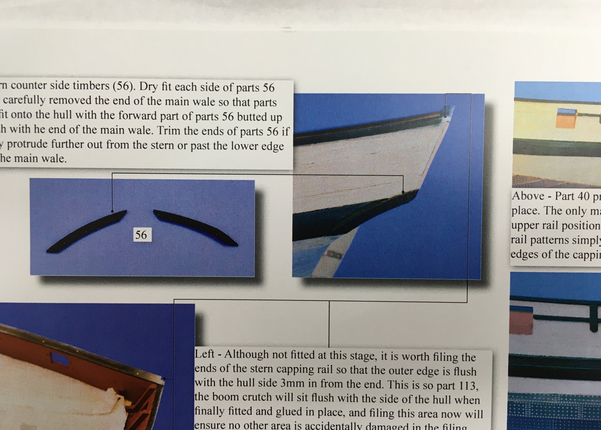
I finally decided to grab the bull by the horns and tackle the stern counter side timbers that had been bugging me for some time. I had been reluctant to chop out part of the wales to accommodate the side timbers, but in the end it proved much easier than I'd anticipated. I sharpened my smallest chisel, and yet again the boxwood showed what a lovely wood it is to carve: After that it was easy to fit the side timbers, with a bit of sanding to get everything flush. With the boom crutches and taffrail fitted and a coat of black paint: I'm glad I fitted the side timbers. It's not entirely clear from the photo, but they add a more elegant sweep to the stern. Next, I'll move on to the prow. Derek


- 725 replies
-
- 10
-
-
- vanguard models
- speedy
- (and 1 more)
-
Hi Glenn Just found your new log. You've made a great start and I shall certainly be following along. I see you've got the little finger plane you mentioned on my log - I'm seriously tempted to go for one myself. I've already got a range of planes including miniature ones, but to borrow your quote about clamps, a man can never have enough planes. I was also impressed with your NMM plan. Those old plans are works of art in their own right - I saw one recently that had been photocopied down to a smaller size and incorporated in the base of the display case. It looked stunning. Great idea for your granddaughter's birthday. All three of my daughters are experienced teachers with five of their own kids between them, but they've all described home-schooling them during lockdown as being "like trying to nail jelly to the wall". I'm not sure jelly has the same meaning in the US, but I'm sure you get the idea. Anyway, best wishes and good luck with Cheerful. Derek P.S. Your workshop is too tidy. You've made me feel bad so now I'll have to go and sort mine out. D
- 778 replies
-
- 3
-
-
- cheerful
- Syren Ship Model Company
- (and 1 more)
-
Pin driver
DelF replied to ErnieL's topic in Building, Framing, Planking and plating a ships hull and deck
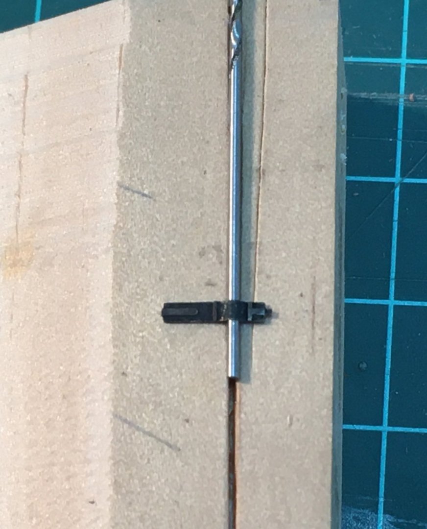
Ernie If you're using the very fine pins that come with your Speedy kit then a nail driver will definitely not work. I know - I tried! With the softer wood used for first planking I found I could push the pins in if I gripped them with fine needle-nosed pliers. If you need to pin any of the harder second planking, for example the wales, you need a pilot hole as others have recommended. Derek -
Thanks Vane - glad it's not just me! Thanks Glenn - I appreciate the advice. The file stand is just a bit of scrap timber. I was fed up with getting files in and out of the plastic wallet. Good to hear you're making the marking gauge I described earlier. I can't claim copyright on it though - like many of the things I've learned in the last few years I read about the octagon gauge on this forum, although unfortunately I can't remember the author. Hope you're getting on with your new plane. Agreed! Derek
- 725 replies
-
- 2
-
-
- vanguard models
- speedy
- (and 1 more)
-
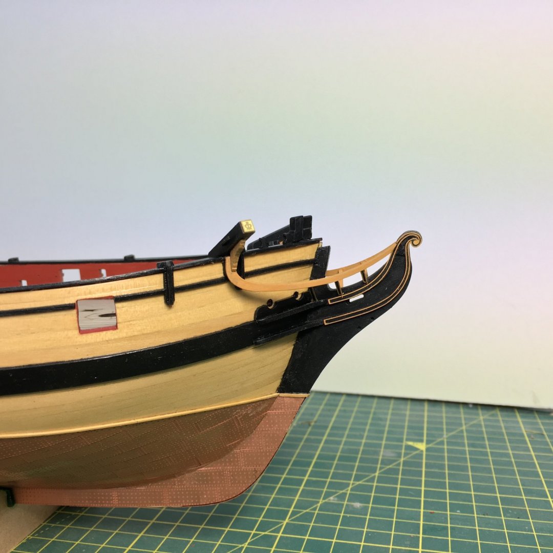
Thanks - much appreciated. I'm just glad wood tolerates mistakes more than some materials. Here's a picture I forgot to post earlier. Mmmm. The upper rails don't quite look even in this view, and they finish inexplicably short of the prow. More tweaking required! Derek

- 725 replies
-
- 8
-
-
- vanguard models
- speedy
- (and 1 more)
-
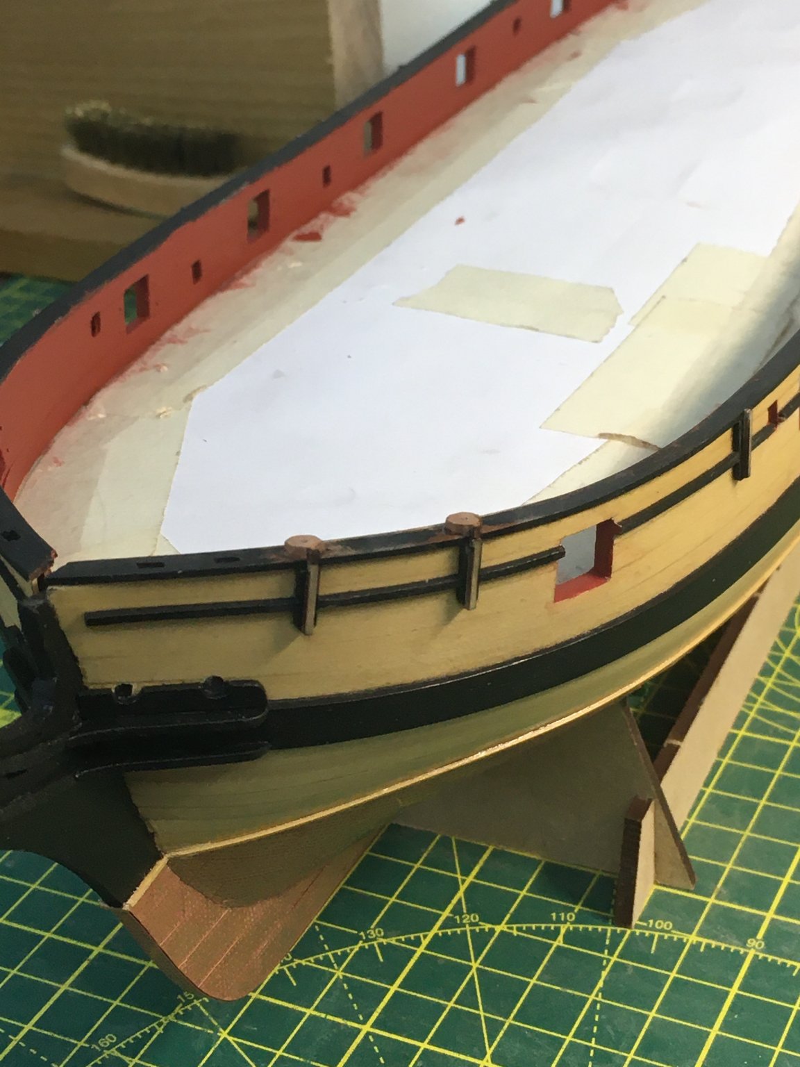
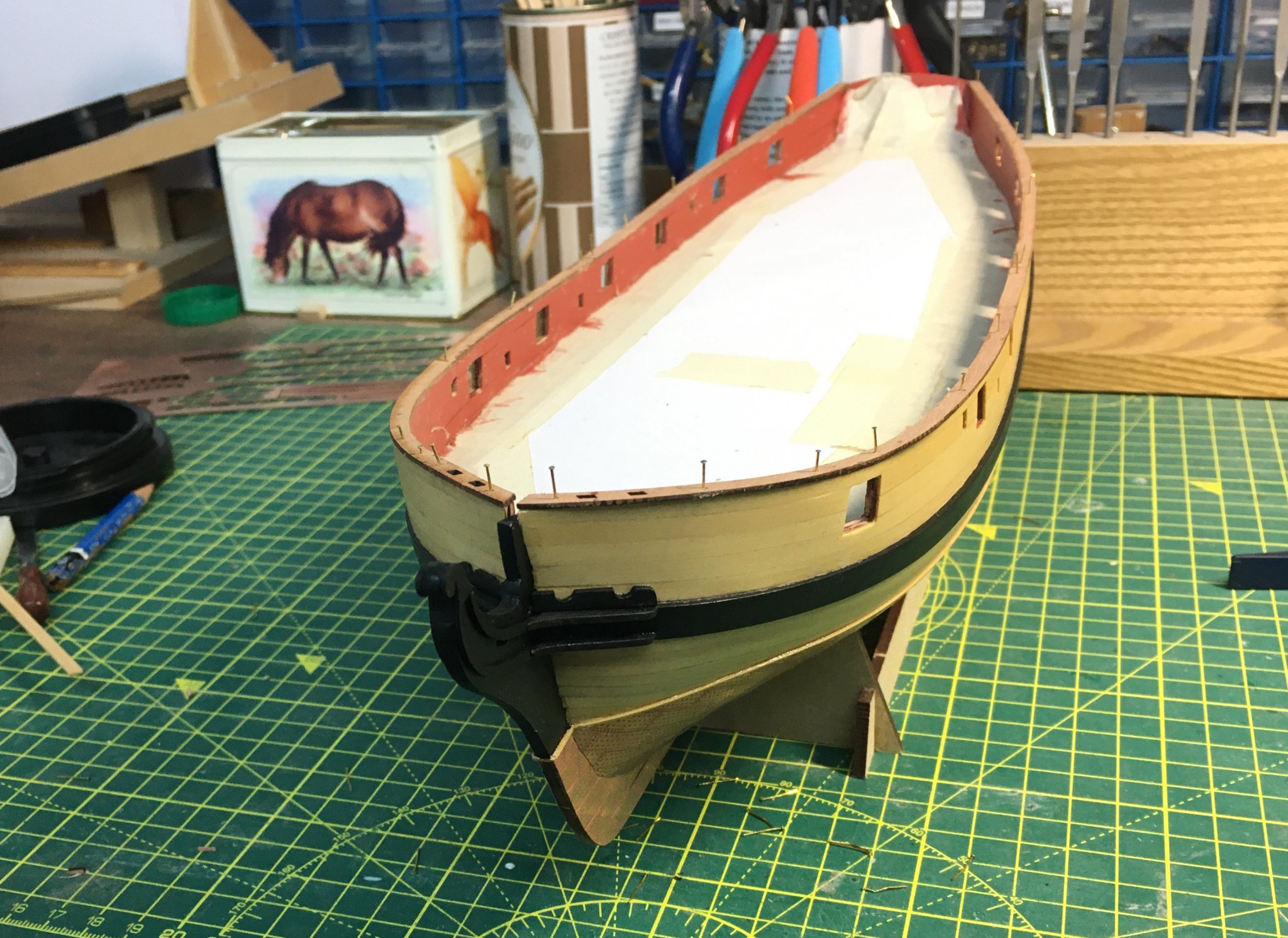
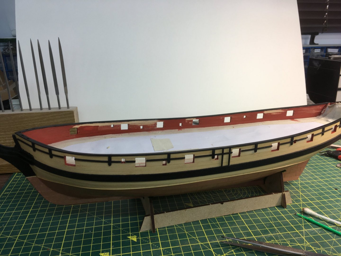
Silly mistakes, Part 2 I said in an earlier post that no kit is idiot proof, and I've demonstrated it again with two more elementary and entirely avoidable mistakes. First, I ignored the instructions and forgot to sand the inner bulwarks before I fitted the cap rails. As a result the bulwarks were too thick in places, with the cap rail flush with the inner bulwark rather than slightly overlapping it. This would look wrong, especially with the pin racks in place, so I had to fix it. I considered removing the cap rails but didn't think I could do so without damaging them. I could have made new ones, but in the end I decided to sand the offending planks with the cap rail in place. I managed the best I could with various scrapers and a small contour sanding tool. The second mistake was even sillier. In order to protect the boxwood I'd applied a couple of coats of matt polyurethane on top of two coats of rubbed-down shellac. Forgetting of course that I had to stick the upper rails and swivel plates to the hull. Needless to say they wouldn't stick, so I had to rub down my carefully applied poly. If the only thing this log's good for is to help others avoid similar silly mistakes (whilst laughing at me for making them!) then it'll be worth it. Painting the rails before fixing them to the hull saves grief later on. Like everything else in the kit these are cleverly designed, made so that the rails run in a continuous line across gun and sweep ports. When stuck firm, you remove the sections crossing the ports with the result that the remaining sections follow the line of the sheer perfectly. The next job was to fit the swivel gun posts and bases - more sanding back of painted surfaces! Finally, after a fair amount of fettling and titivating I reapplied the matt poly. The boxwood is really starting to look the part. Before I go much further I need to decide what to do about the stern counter side timber. But that can wait 'til tomorrow. Derek

- 725 replies
-
- 16
-
-
- vanguard models
- speedy
- (and 1 more)
-
Welcome aboard Ernie. The quality of kit models has come a long way in the last 40 years and you've picked a particularly good one. So do I, but I still make mistakes as you'll see from my Speedy log - must be an age thing! Derek
-
Hi Messis Treenails are very much a question of personal taste. In reality, they would be virtually invisible even at 1:48 scale. Some people like to show them, but they run the risk of the treenails looking far too prominent - like the ship has measles! If you paint Caroline as I did (here) then there are few bare planks on the exterior hull - I think treenails on these might look odd. I didn't show treenails on the deck planks either - if you want to show treenails I would just use a very light pencil mark rather than drilling holes and using real treenails. But as I say, it really is a matter of personal taste - it's entirely up to you and what you want. My only advice is, if you are going to show treenails do it subtly - don't make them too obvious. Best wishes Derek
-
That's looking really good Mark - well done for persevering. Derek
-
Thanks Glenn - very helpful. I agree - it's the one area that's not covered as well as it might be in an otherwise excellent manual. Of course, the manual is light years better than most others - it's just that people like Chris and Chuck have spoilt us. Derek
-
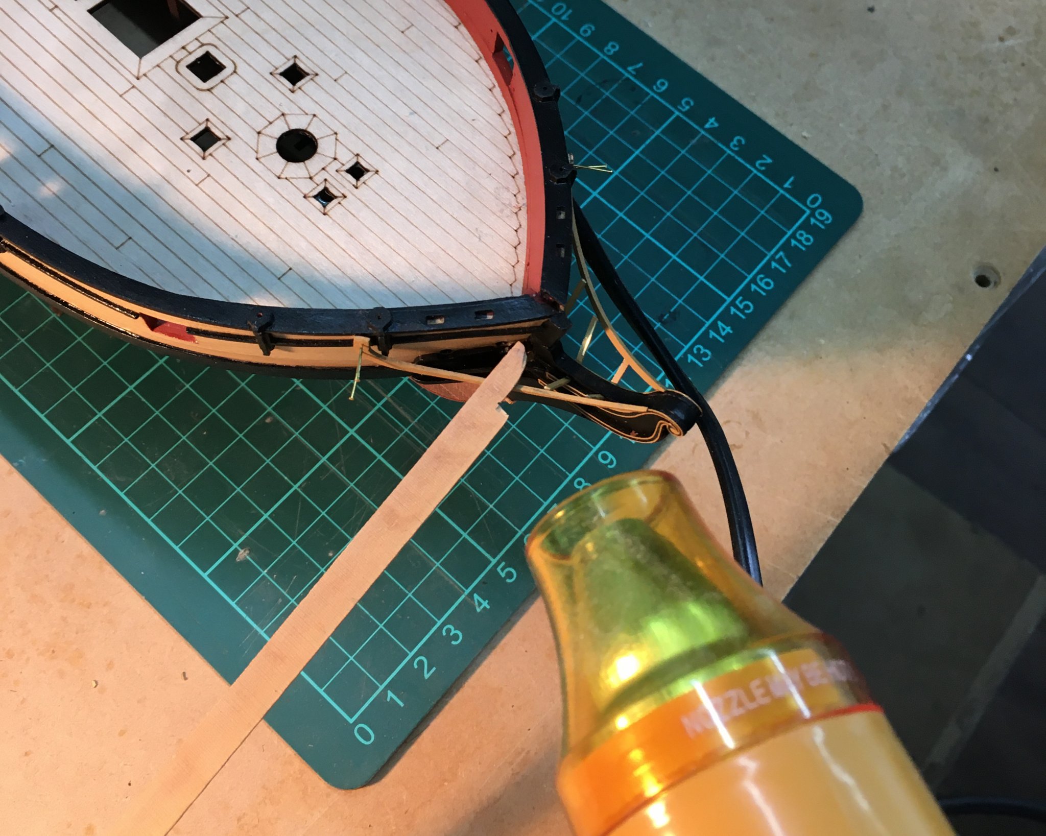
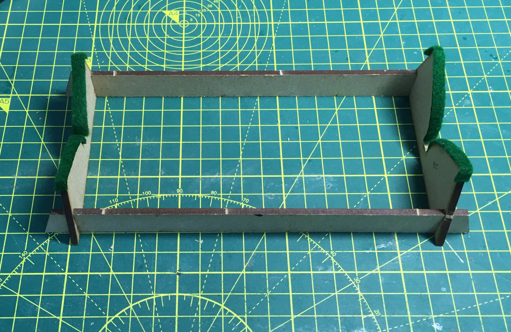
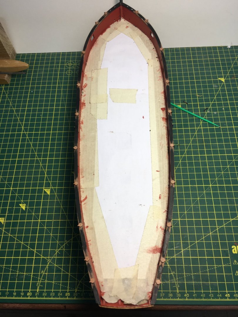
I wish I had friends like that! A few bits of work on the hull yesterday and this morning. First, I scrounged some felt from my wife's craft stash to line the building cradle so I don't damage the copper. Next, the hair brackets and bow cheeks were fitted both sides of the prow. These are laser cut pieces, requiring a minimal amount of sanding to fit in place: Then I had my first breakage. The cap rail comes in four parts, laser cut in 1mm wood. Sanding the char I manage to snap the end off the starboard bow section. However it was easy to repair with a dab of glue. You can just see the split across the first rectangular hole, but it won't show once painted. Here's the cap rails pinned and glued in place. Just to prove that no kit is idiot proof, the next repair job was self inflicted. The outer edges of the cap rails have to extend 0.8mm from the hull to accommodate the swivel gun bases. In the bow area I got this wrong when I glued and pinned the cap rail, with a wider overhang. As a result there was no overhang inboard, and it just looked bad. I didn't want to risk pulling the cap rails off; I also think the hull is wider towards the bows, given the way I had to twist the gun port pattern to get it to fit. I decided to cheat by gluing thin strips of wood to the inside of the cap rails and filing them to shape. I don't think the result is too horrendous, and there is now a more even overhang inboard. Here she is with the cap rail painted and hawse holes drilled. The recommended 2mm diameter holes look a tad small to me, and I might widen them slightly. I've now got a question to resolve regarding the stern counter side timbers. The instruction manual shows how these fit at the end of the wales, requiring the latter to be trimmed: From the pictures in the manual it appears that Chris trimmed the wales at a much earlier stage, before painting. I'm finding it difficult to see how the side timbers are meant to fit, and I'm reluctant to trim the wales and risk damaging the hull if I'm not certain. Reading ahead in the manual, I think the boom crutch needs to sit on top of the side timber so I can't leave it off all together. So I might just see if I can just fit the upper, curved part of the timber on top of the wale without cutting into the wale itself. Looking at the photo in the manual I think the net result would be the same. I'll check other people's logs who are further ahead than me before I commit to that. Derek


- 725 replies
-
- 7
-
-
- vanguard models
- speedy
- (and 1 more)
-
John The piece on Understanding Ships' Draughts was split into six articles in issues 46, 48, 50, 52, 54 & 58. David White also wrote a series of nine articles on Traditional Wooden Shipbuilding in issues 47, 49, 51, 53, 55, 57, 59, 61 & 63. Plus lots of others on topics as diverse as load lines and boat davits. Busy man! Unfortunately I can't copy these articles. Leaving aside copyright issues, the magazines have stiff covers and I can't lay them flat without breaking the spines. However, as Thunder says Model Shipwright copies regularly appear on ebay. I didn't start subscribing until about 2000, but a few years ago I was able to get all the back copies in relatively short order without breaking the bank. Derek
-
That looks like a beautiful tool. Alaskan yellow cedar should be an excellent alternative to boxwood. I tried to get hold of some over here when I saw Chuck use it on the Winchelsea group project, but it only seems to be used by high-end boat builders and in large and expensive sizes. If I lived near a boat yard I'd be tempted to beg offcuts, but as I don't I'll have to make do with boxwood. Derek
-
I loved building Caroline and will follow your log with interest. The kit allows lots of scope for improvement and adding extra detail - I'm sure you'll enjoy it. Derek
-
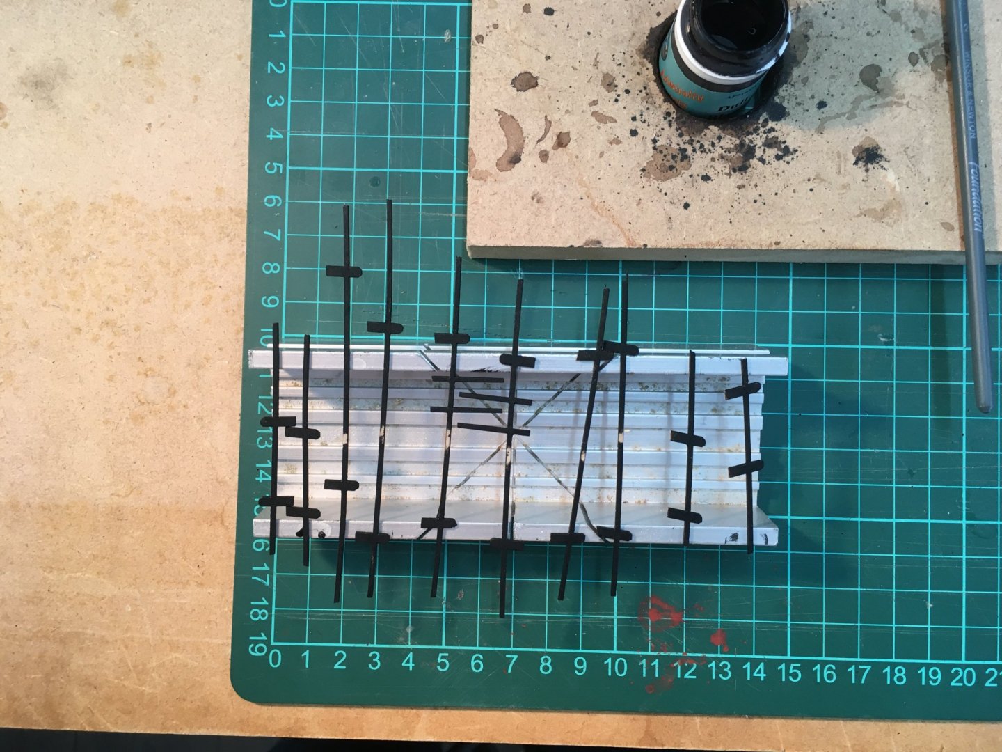
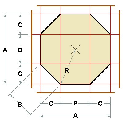
Thanks Glenn - great that you're planning to have a go at making spars from square stock. I found it daunting at first and needed a couple of practice sessions, but if you mark your work carefully, use a nice stable planing jig and a sharp well-adjusted plane it becomes surprisingly easy and enjoyable. It's particularly gratifying to be able to make spars with combinations of square, octagonal and round sections. Just out of interest, what plane have you ordered? As for marking, in the absence of a jig it's just down to a sharp pencil and an accurate ruler. Or possibly a miniature version of a carpenter's marking gauge? Here's an example from Blue Ensign's Pegasus log, where he uses the 7:10:7 method to draw his lines prior to planing. I wouldn't worry about being hyper accurate - even the 7:10:7 ratio is just an approximation. You can work out the correct value from high school geometry, but for the lazy among us there's a neat online calculator at http://www.liljedahl.info/projects/octagon_calculator/. The calculator lets you input one any of the dimensions of an octagon in the diagram below and it will calculate the others. So if your stock is 24 units wide (for ease of calculation), ie dimension A, then the calculator tells us that C:B:C is 7.03 : 9.94 : 7.03. Close enough to 7:10:7 in wood, and at our scales. There's another calculator at https://rechneronline.de/pi/octagon.php which is even more comprehensive, and gives access to calculators for lots more geometric shapes. So long as you don't plane too much off the corners, sanding your spar in a lathe/drill should even out any slight inaccuracies in your octagon as you reduce it to round. To answer your question on boxwood, I get mine from a UK supplier here. Unfortunately they don't ship outside Europe. However their castello boxwood comes from South America so I should think you'd be able to get it in the States. It seems expensive - the 6mm sheet I picked for illustration in the link is £25.20 - about $31. However the 1060 X 140 mm sheet will produce a lot of spars and planks - if you mill your own it probably works out less expensive than cheap timber bought ready sized. Let me know how you get on with your new plane. Derek
- 725 replies
-
- 4
-
-
- vanguard models
- speedy
- (and 1 more)
-
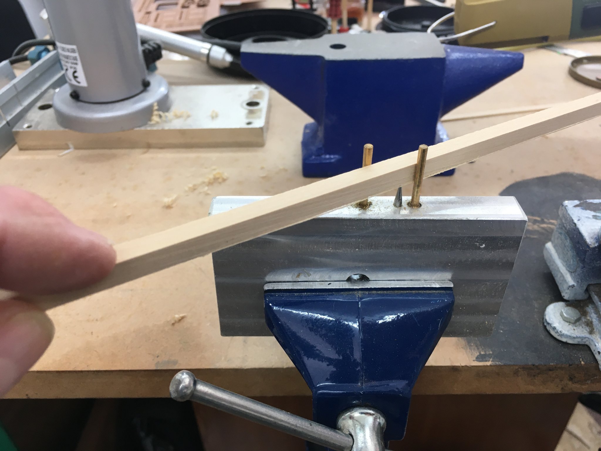
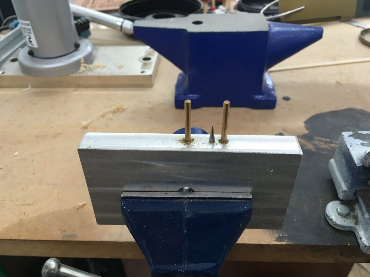
Thanks Eamonn! Sure, glad you found it helpful. The brass pegs are 2.5mm. Not crucial, but thinner is better - too thick and I think it throws the ratio out. The centres of the pegs are 17mm apart, and the steel pin is 5mm from the centre of one pin. The pegs and pins are just fixed in holes I drilled in a piece of scrap aluminium. One word of caution - don't scribe too deep or it'll be difficult to sand the lines out without reducing the diameter of your stock too much. I should add that I decided to do this how-to piece after Glenn Barlow started an interesting discussion on Chris Watton's thread about the possibility of boxwood spars. I made all the spars for my Royal Caroline build in a similar fashion, including yards with octagonal centres etc. Definitely my favourite technique. Derek
- 725 replies
-
- 4
-
-
- vanguard models
- speedy
- (and 1 more)
-
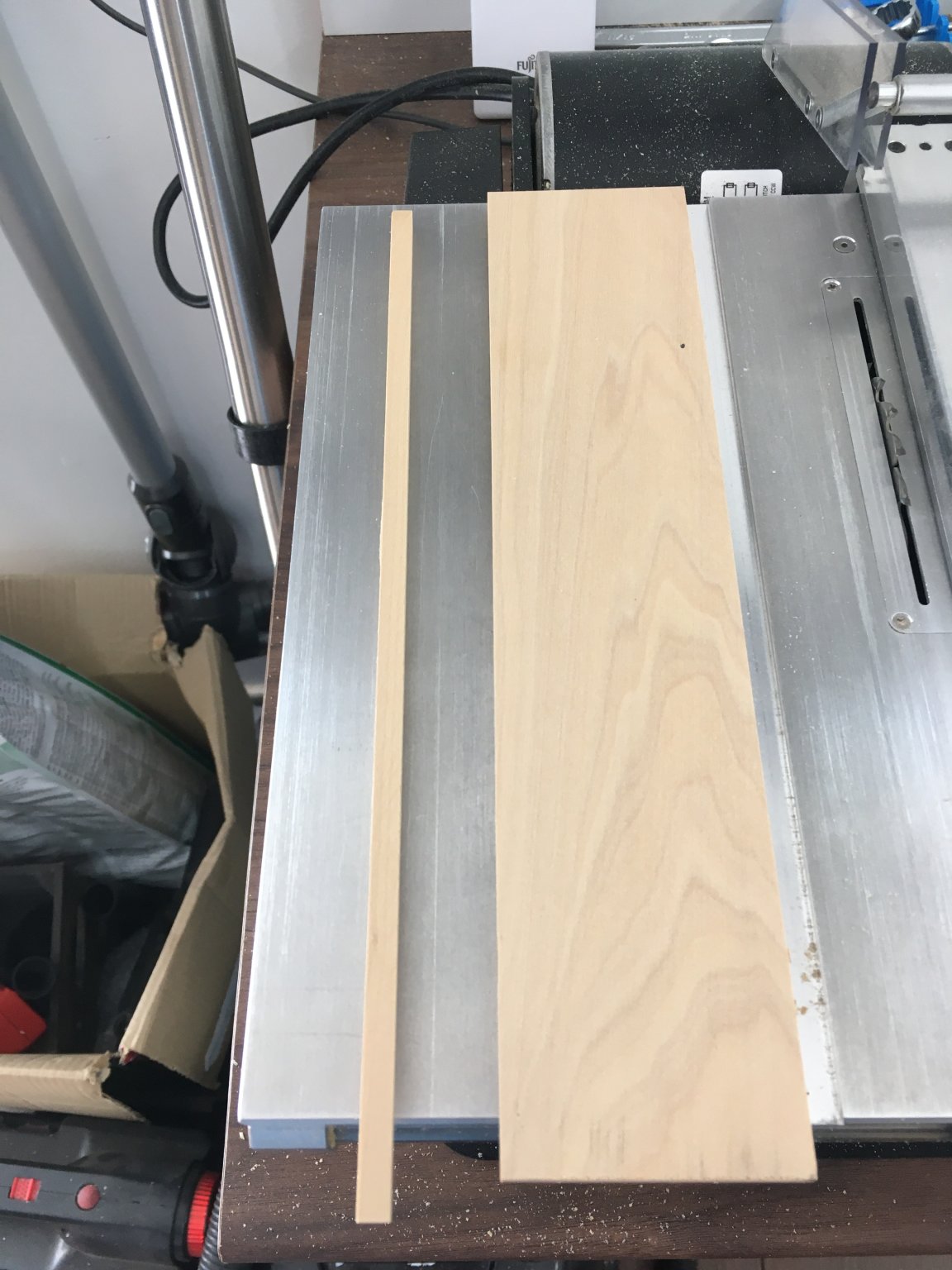
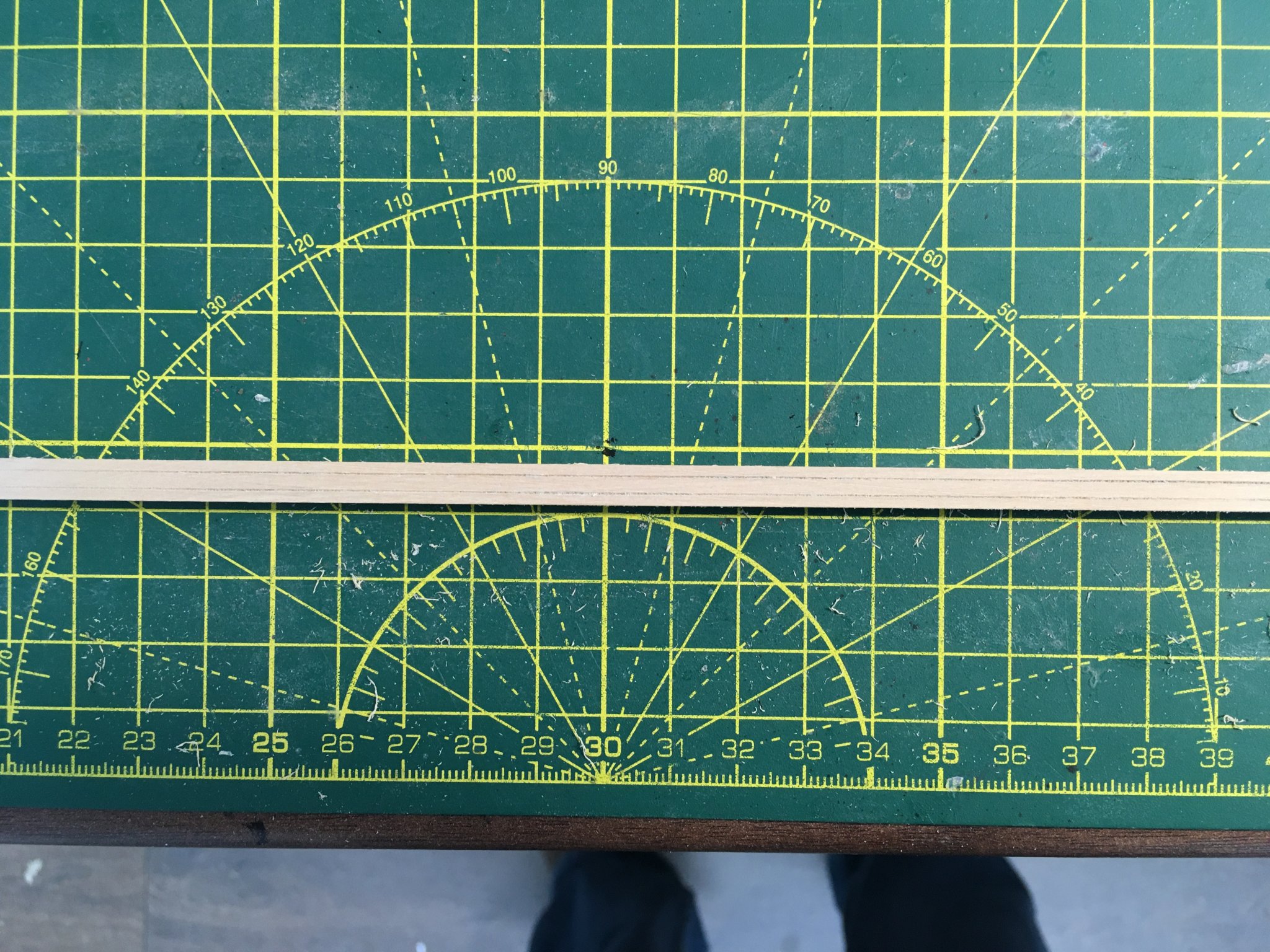
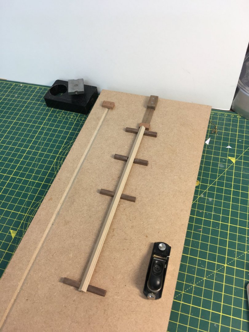
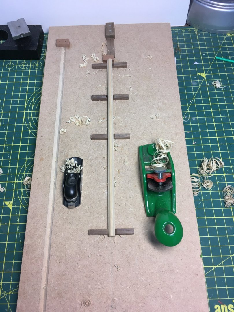
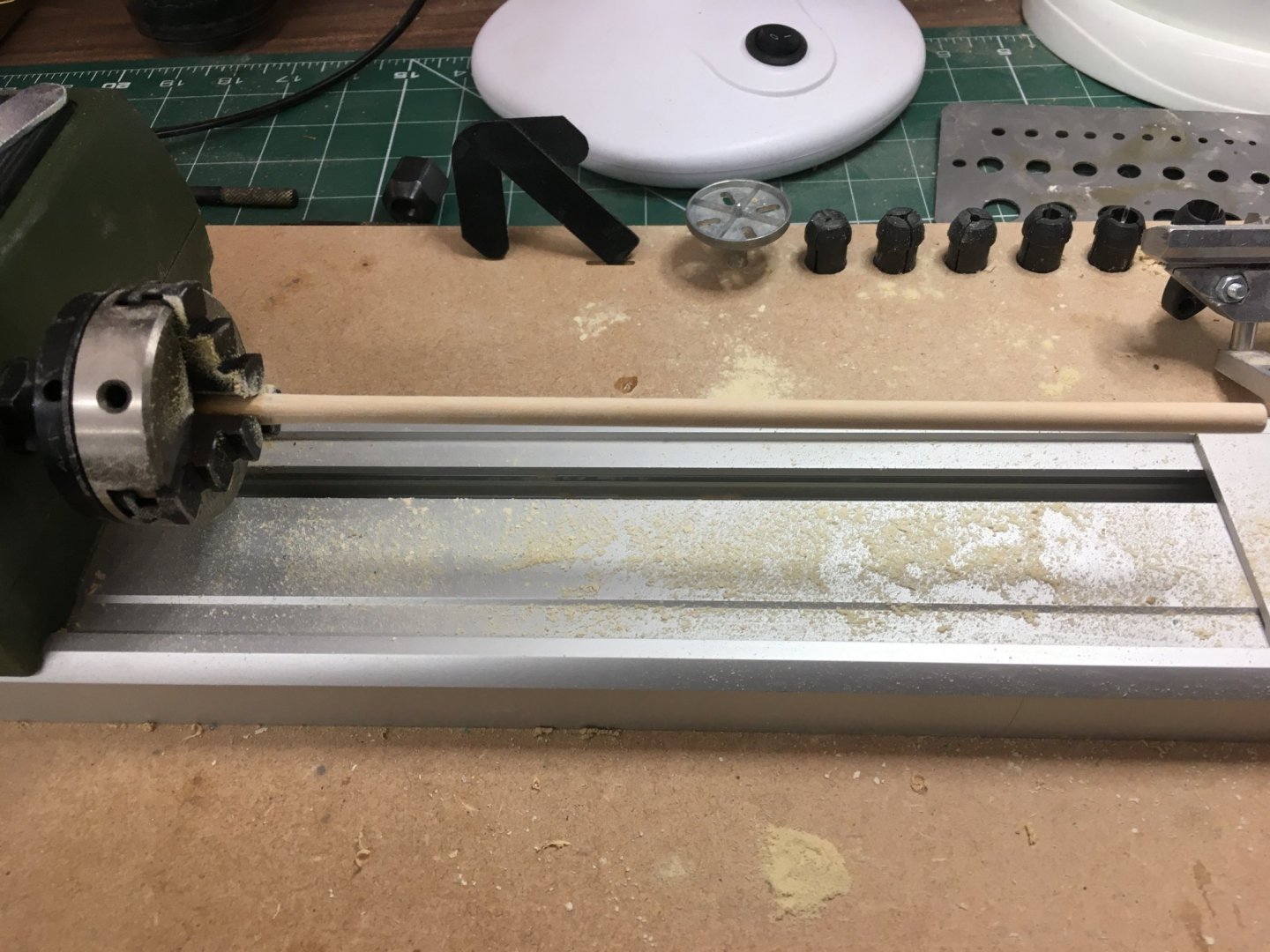
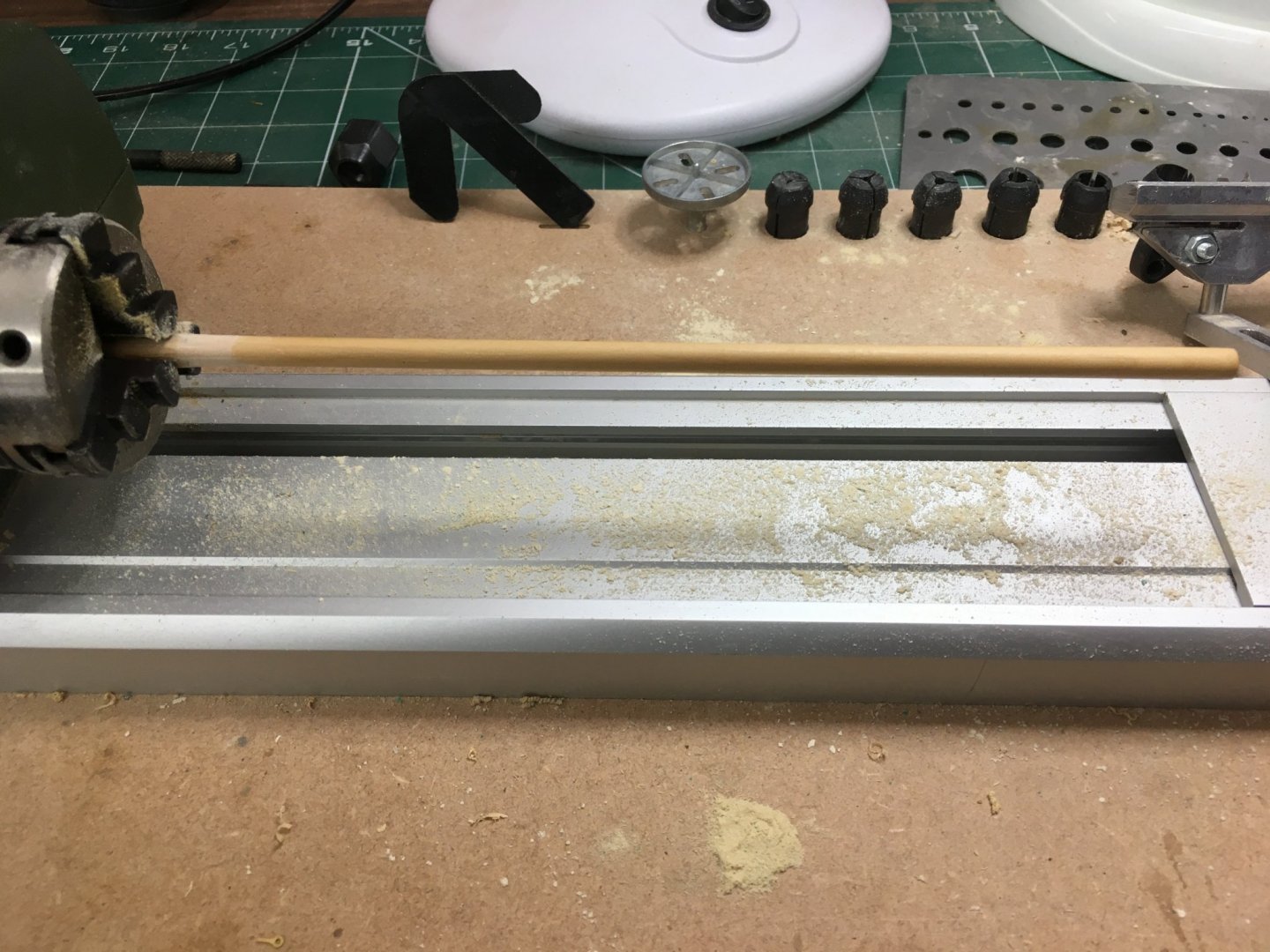
I thought I'd have a break from the hull and cannon and show how I intend to make the spars for Speedy from castello boxwood sheet. I've gone for the bowsprit as it is a reasonable size to demonstrate the method. The bowsprit is 6mm diameter, so the first step was to rip a square strip from 6mm sheet. I made it over-length to allow for trimming and to allow sufficient waste to grip in the lathe. The next step is to reduce the square section to an octagon. Some years ago I made a little jig to mark square stock prior to planing: The idea is to pull the stock between the two brass pegs, making sure that the wood keeps in contact with both pegs and the marking pin between them. When you've made one pass, you turn the wood round end to end and pull the wood through again. You repeat this for all four faces, ending up with two scribed lines in each face. So what, you say? The idea is that these two lines divide each face in the ratio 7:10:7, which ensures that when you plane each corner down to the lines, all eight resulting faces will be equal. The beauty of the little jig is that it doesn't matter what size the stock is - provided it will fit between the pegs, the scribed lines will always be in the correct ratio. When I made the jig I had to work out the spacings and the diameter of the pegs from basic geometry but if anyone's interested I could post the measurements. Here's the next stage, using a standard planing jig. Starting with the green Stanley 100-type finger plane and finishing with the Veritas low-angle block plane it only took a few minutes to reduce all four corners. On to the lathe - although a drill or Dremel-type rotary tool would do equally well: Again, it only took a few minutes to sand the dowel down to a reasonable round section. I started with 120 grit and finished on 600. A quick coat of shellac which protects and imparts a nice warm sheen and the bowsprit's finished, bar trimming to final length. I'll make the remaining spars in due course. Even if you can't get hold of boxwood, I'd certainly consider using a lighter coloured wood than walnut if you can. Derek
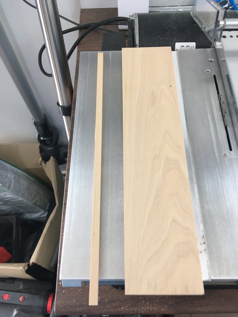


- 725 replies
-
- 17
-
-
- vanguard models
- speedy
- (and 1 more)
-
Thanks guys, much appreciated. I didn't know what you meant Glenn, until I looked at the post on my iphone. Yikes! I've edited and hopefully it's OK now. Derek
- 725 replies
-
- 1
-
-
- vanguard models
- speedy
- (and 1 more)
-
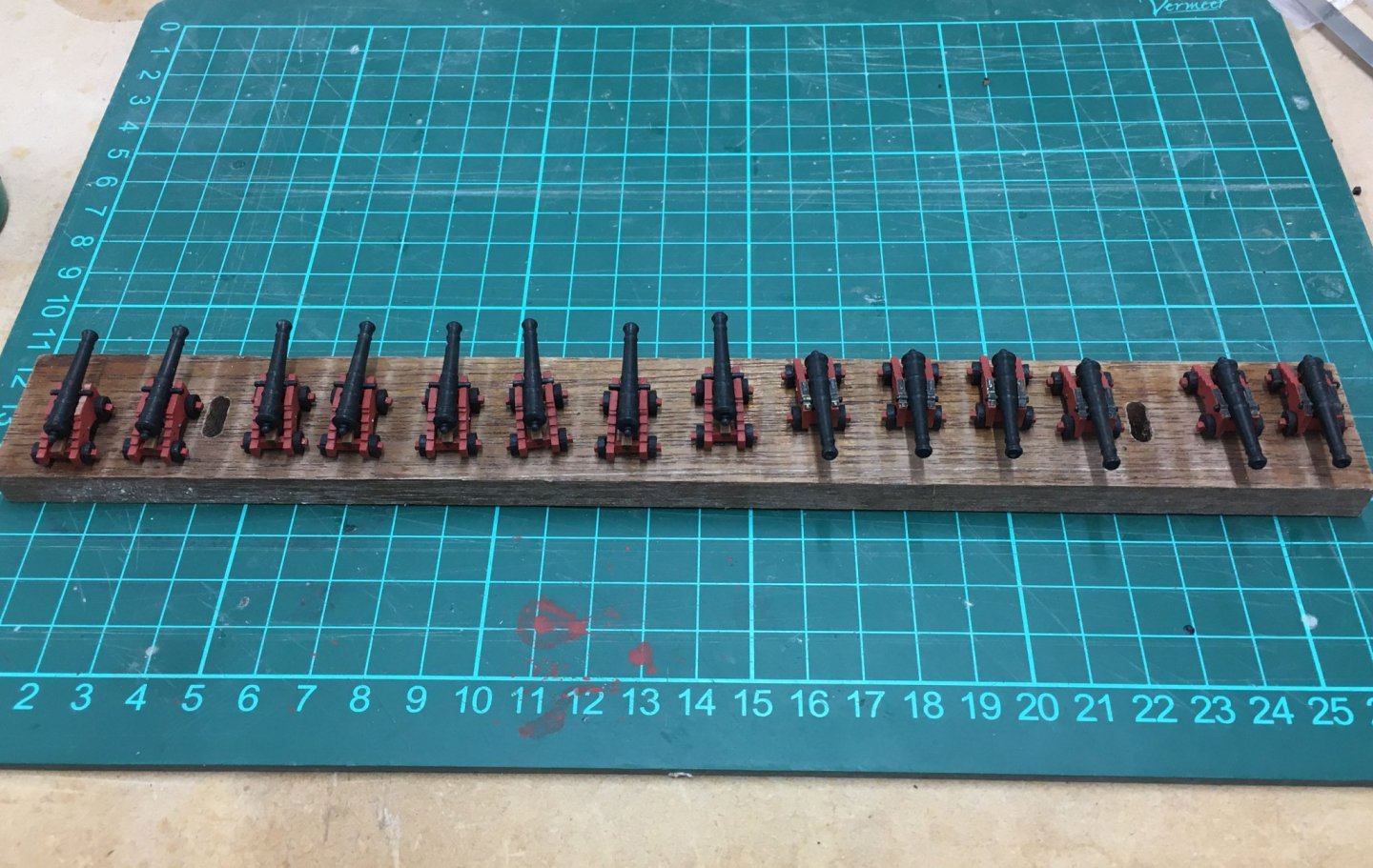
Limited progress this week as I've been taking advantage of the fine weather to get jobs done in the garden (that's manspeak for trying to cross off a few of my chores from my wife's lengthy list). First job was painting the wales and prow. I started by masking off the unpainted areas but made a mess of it. Paint seeped through in some places, and in other the tape pulled bits of paint off the top edge of the wales. I used good quality tamiya tape so I don't believe that was the problem. Rather, I think my mistake was applying several coats of matt polyurethane to the unpainted areas before painting the wales. Some of the varnish got onto the wales and prevented the acrylic adhering properly. So, after much sanding, cleaning and swearing I went back to basics and repainted the wales with as steady a hand as possible. The result is certainly better than my original attempt (which I was too disappointed to photograph ☹️). Meanwhile I've made some progress with the cannon, starting with a little jig to shape the cap squares. It's just a drill bit the same diameter as the trunnions, half-sunk into a groove in a piece of wood. Once in place I just use a thumbnail either side to press the little piece of photo-etch into shape. Just makes it a bit easier to fit to the carriage. As for that, I started using CA but found I couldn't always get the cap square sitting properly before the glue set, so now I use PVA. Not ideal but it's not load bearing so it shouldn't matter. The cannon are coming along, but you'll see that the blackening process didn't work too well on the cap squares. I think it was because I tried to do too many small pieces all together, and I couldn't agitate them enough to get them all evenly treated. I'll touch up with Admiralty metal black when I've finished them all. Back to the chores! Derek
- 725 replies
-
- 14
-
-
- vanguard models
- speedy
- (and 1 more)
-
Hi Mark I share your pain - Speedy is also my first attempt at coppering and it's not easy. I got some good advice from Glenn - see the link here. I used Gorilla CA gel, applied with a toothpick. Rather than one blob in the middle, I applied five tiny blobs - four near the corners and one in the middle. Otherwise I found, like you, that the corners didn't stick well. With practice I found I could judge the size of the blobs so none squeezed out. If it did, I tried to wipe it away immediately. For that, I used acetone on a small pad made from a piece of an old cotton shirt. I found with some blobs of CA that I had to rub for quite a while to remove all traces, especially if I'd allowed the glue to dry. It will all come off eventually. I should also add that I wear rubber gloves when coppering - partly to protect my hands but mainly to prevent fingerprints tarnishing the copper. I found Glenn's advice about how to line plates up with the leading edge of the preceding pate (I used tweezers) and adjust them with a metal pointer particularly helpful. It's worth getting this right, because if a plate is just a small fraction of a millimetre off line it catches the eye. Better to lift it and try again if you can't nudge it into place before the glue dries. Hope this helps, and I hope you feel you can persevere with Speedy. Derek