DONATION DRIVE - SUPPORT MSW - DO YOUR PART TO KEEP THIS GREAT FORUM GOING! (91 donations so far out of 49,000 members - C'mon guys!)
×

Bedford
-
Posts
1,297 -
Joined
-
Last visited
Content Type
Profiles
Forums
Gallery
Events
Everything posted by Bedford
-
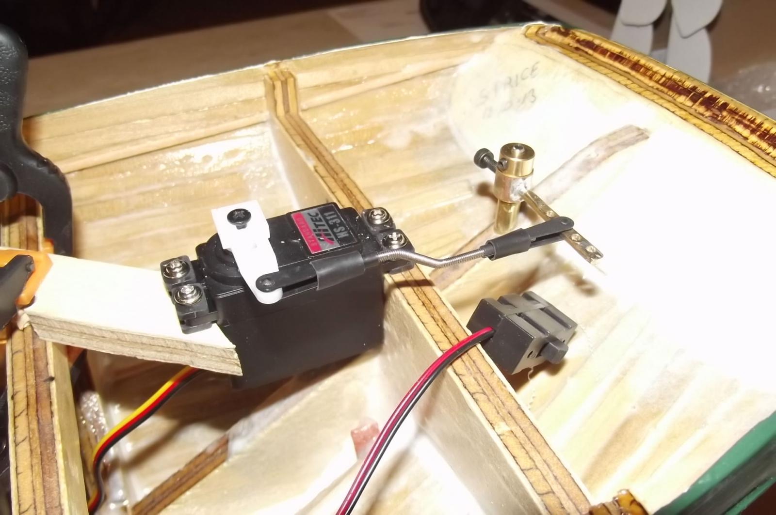
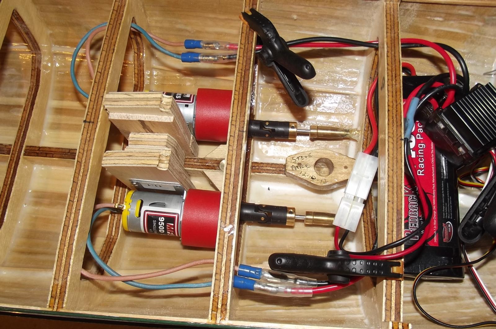
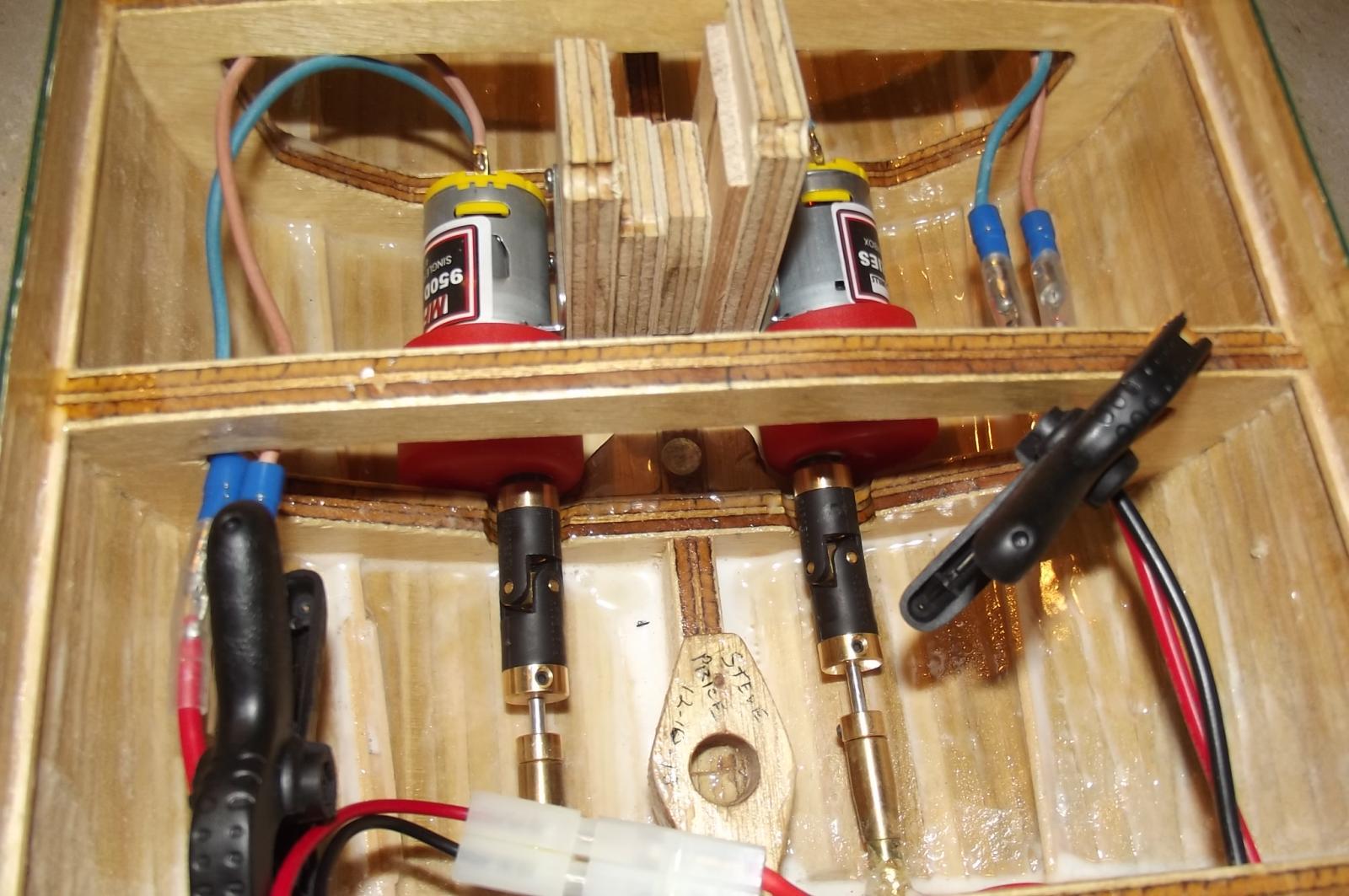
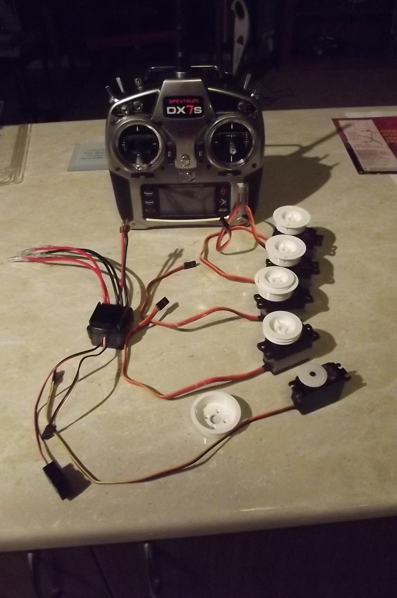
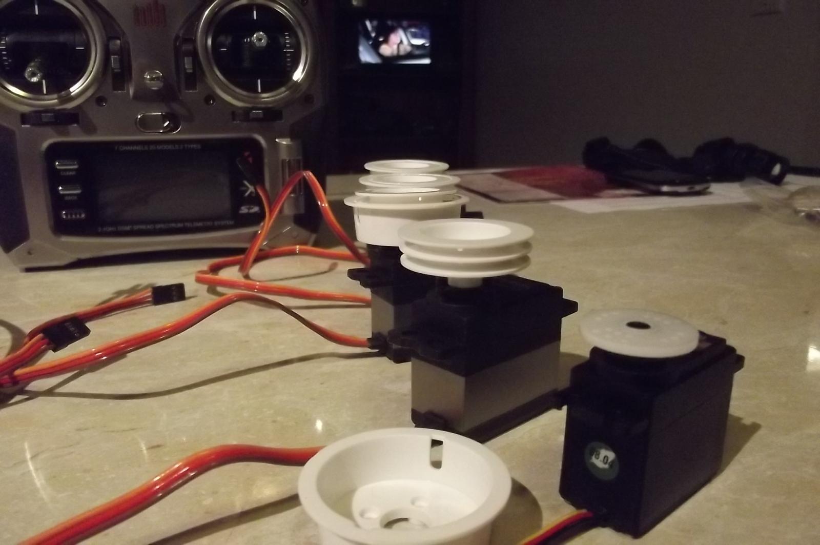
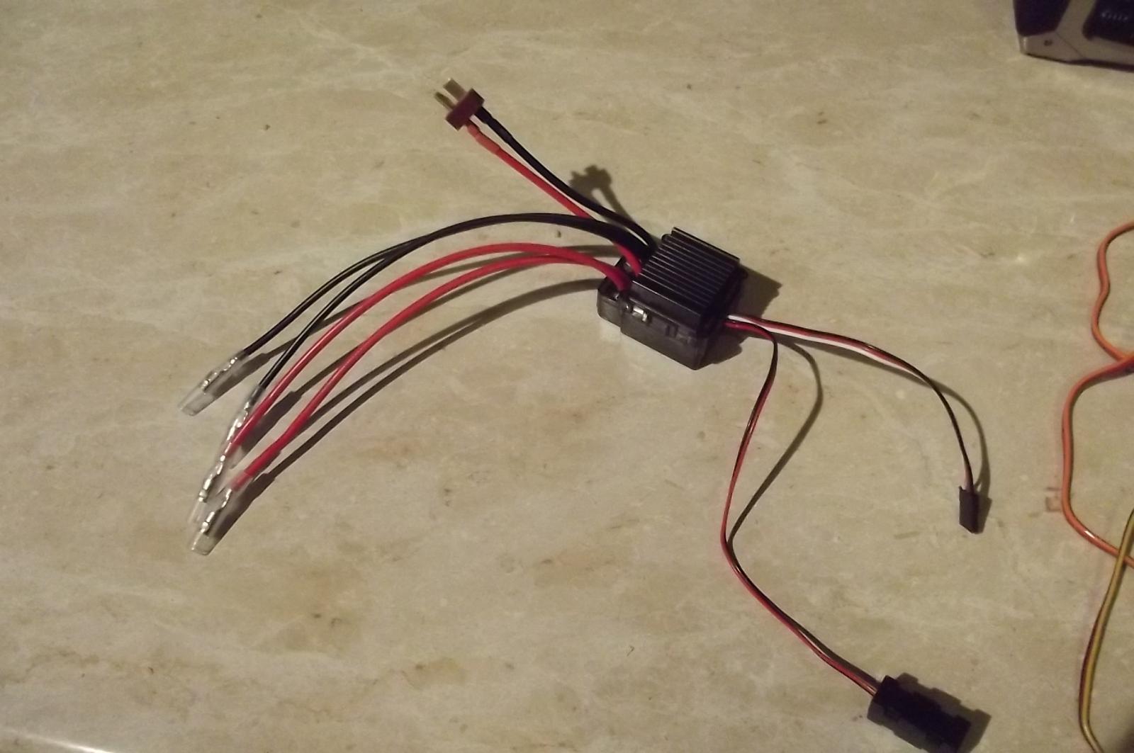
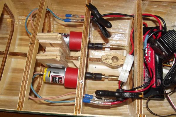
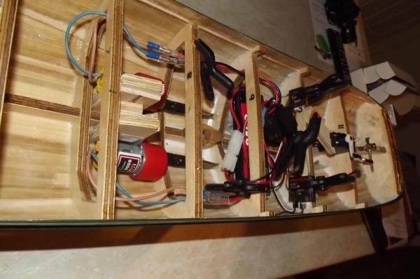
 My goal this weekend was...............sea trials! I set up the motors and made the steering arm etc but when I came to charging the onboard battery I found that my old charger has died a horrible death so I was unable to power it all up. These pics show a real mess but it is all just jury rigged for sea trials. I need to see if the motor / prop combination will provide enough thrust before going much further. Helm control with temporary servo mounting Motors, battery and speed controller, temporary mess The whole mess The motors, like everything else, are temporarily mounted.

-
I have to make the sails for my schooner, my wife was quite a good seemstress and had a very good sewing machine with feet for just about anything you could want to do. I should have built the schooner before the divorce Now I am in your boat and have to do it myself. Steve
-
Nils, we could jump ahead and look at the completed model in the appropriate gallery but that would be a huge spoiler. I am checking on this build every day to see what new pics you have put up. It is fascinating. Such beautiful work and craftsmanship. Steve
-
New parts have arrived in the shipyard...................now it really gets interesting The winch servos look good and they are nice and heavy so hopefully that translates into strong! The speed controller for the motors is designed for a 4wd buggy with two motors, convenient! Now to start planning the controls in ernest.


-
John, just a little note on the colour of the Craig when she was brought into the haorbour 20 odd years ago. I found pics the other day and she was a light blue and another colour, I think just whatever they could get cheap to paint over the rust and make her look a bit presentable. I first saw her on the pontoon dock next to the "South Stien" in Darling Harbour during the bi-centennial celebrations and she was painted brunswick green then. Steve
-
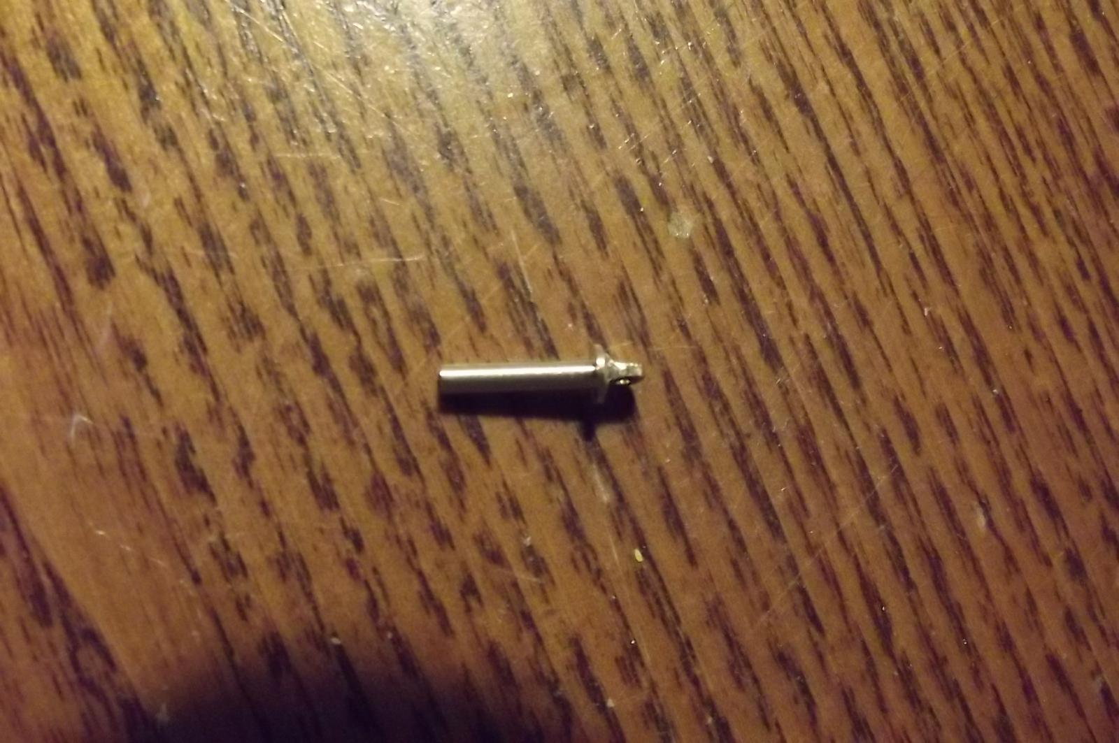
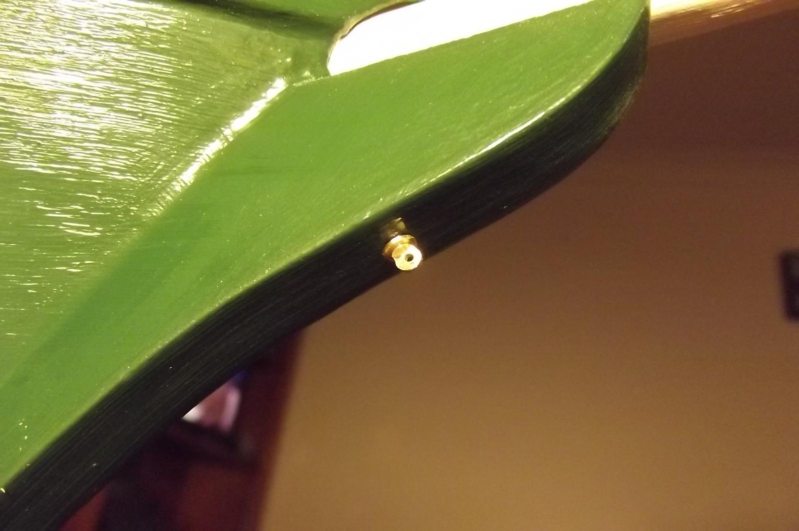
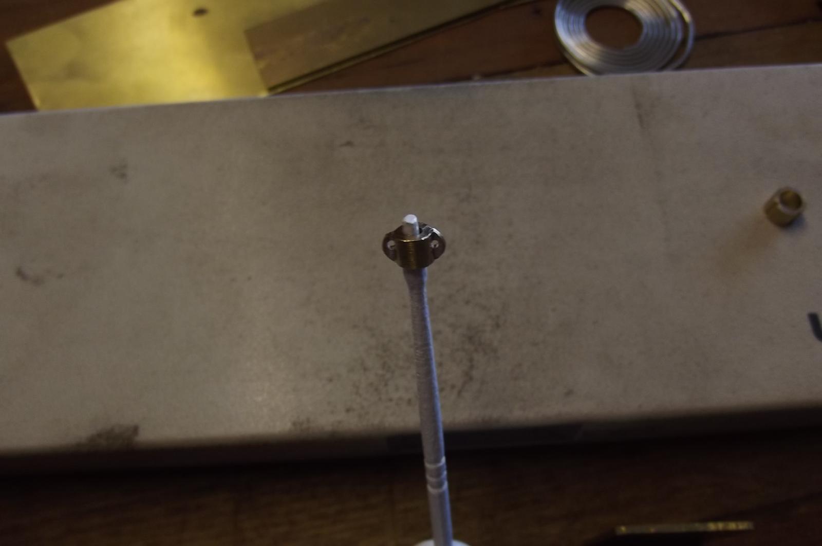
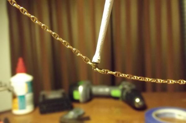
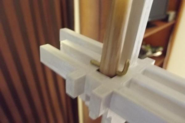
More progress, the chain is partially fitted and I have turned an eye with which to attach the other end. The eye pin has a 2mm shaft, then the flange was turned to 4mm and the eye loop was formed by filing.


-
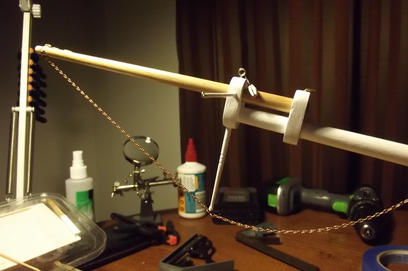
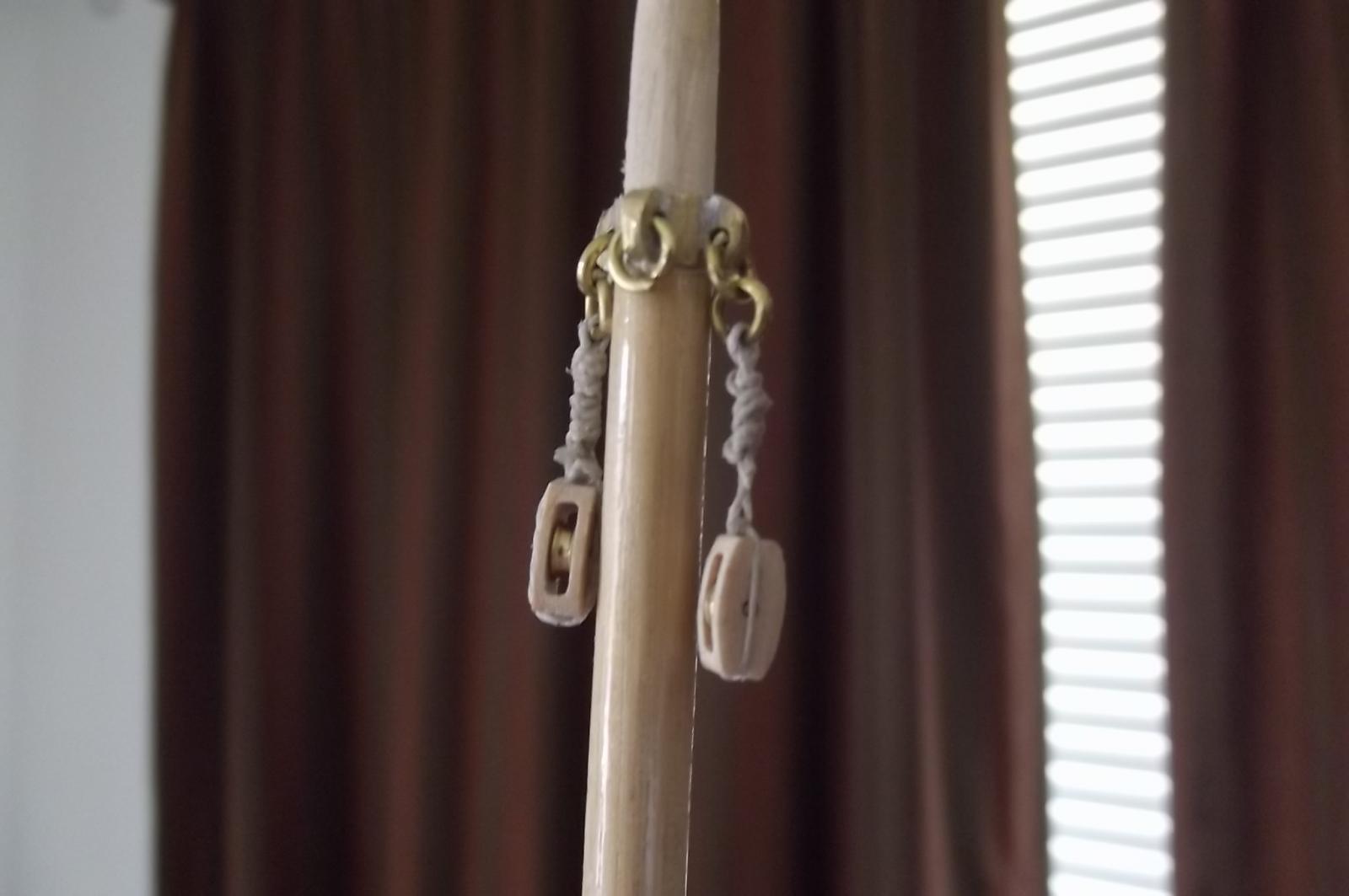
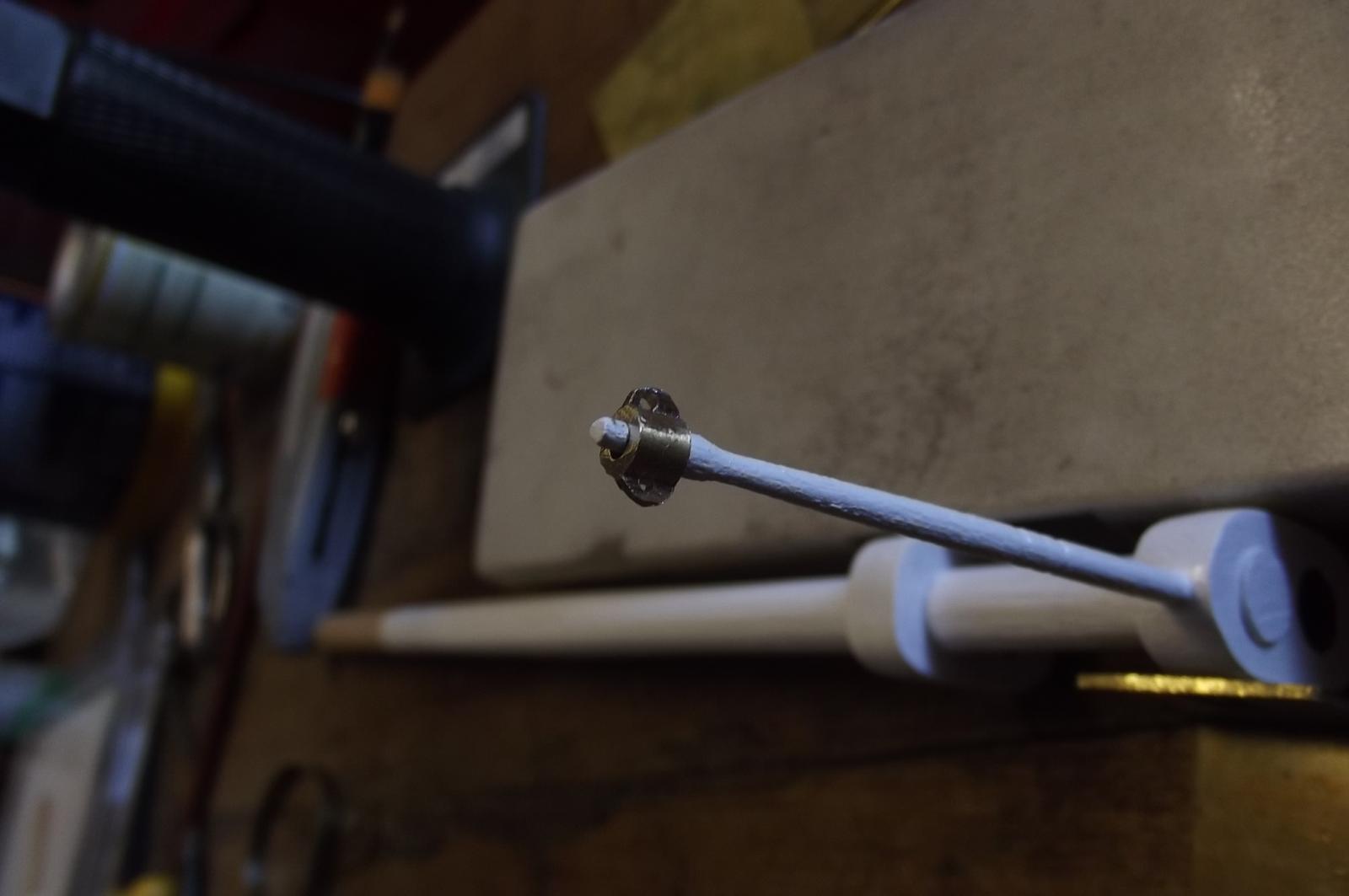
I find myself more and more getting bogged down with planning and details to the point I sit and stare at her thinking about how to do this and that and not actually achieving much. This weekend was considerably cooler thankfully and it rained, I had heaps to do around the house because I had been too tired from the heat to do it. I got all caught up and decided to just do SOMETHING to the ship and what do you know? Some of the things I had been agonising over just happened. First, I can't remember what I was thinking when I glued the eye collar onto the dolphin striker that made me put the eyes at 90deg to the bowsprit ( I'm sure there was profound logic behind it at the time ) I ended up cutting it off and drilling up the center of the timber to accept an eye pin so I can attach a chain from the end of the bowsprit jib boom via the striker to the bow. Then I looked at the line of the horizontal stays for the bowsprit and realised I needed to stand them off so as to allow free movement of the anchors so I added the timbers to do that. The chain is a studded anchor chain, I have used this because the normal brass chain with open links has a certain amout of elasticity. This is a closed link chain and will take the strain. The strain has been a big stumbling block, ie:- will it last, will it hold, do I need to design something better, these questions are comming up for everything I do now but I have decided to just build it soundly and if something does need to be re-engineered stronger it will let me know. I am doing the rigging for the blocks in a simple yet strong way by twisting 0.5mm cord together leaving an eye which I then pass the ends through to form a loop into which goes the block. The block is then placed over a pin on my cutting board and the tail is passed through an eye hook screwed in about 12mm away. I then run the tail up beside the block and clamp it there and use another piece of 0.5mm cord and tie it around the tail, knot after knot all the way up to form pseudo siezing, I cut the ends of the tail a bit short of the block so they get covered by the siezing and when all is done I put glue on my finger and thumb and squeeze it into the rope while rolling it between my fingers. Some are not very neat, they were done when I should have been in bed. They will not stand out in the overall ship though, especially when she is under sail.


-
Well I have been a bit quiet lately, mainly because of the heat and all the planning, it has left me a bit brain fatigued. Orange is a place that can get snow in winter and normal summer temps are in the order of 26 to 28 deg C with the odd day of 30 ( that's 79, 82 and 86 degrees respectively for the imperialists) but the last two weeks or so have been up around 33 and 35 deg C or 95 deg F and thats just too much for me because I never did handle heat well. The upshot of all that is that when I muster the energy to work on the ship I only do what I can without leaving the air conditionned comfort of my house and entering the stinking hot garage. Tonight though the temp has dropped and it has rained, and we really need that because most of the country is in drought, and it looks like a few nice days comming up. So, to the progress..... I am working on the blocks etc, fitting them to the masts, booms and gafs. I created a flat on the side of the booms and gafs to accept the blocks and glued them on with a simple butt joint but I wasn't happy that this would be strong enough. So I drilled into the boom/gaf at each end of the block and bent up brass wire which I epoxied to the block and into the boom/gaf and I feel much more confident now.


-
Again, if memory serves, I seem to remember reading about her at the Sydney Maritime Museum - not to be confused with the Australian Maritime Museum in Sydney - that she was trying bulk loading for the first time like the non sail ships did and had a hold full of wheat. She encountered a storm and the hatches were letting water in. The grain on the leeward side of the hold became saturated which caused her to heel over more and the fact that the grain was free to move around in the hold meant it all tried to get to the lee side and she capsised. I was there not long after the James Graig was brought to Sydney so that was about 20 years ago, I will therefore stand correction
-
From memory she used to frequent Sydney along with her fellow "P" line ship, the Passat. Not sure which but one of them was the last commercial tall ship to sail out of Sydney on 1957. I will keep a close eye on this one.
-
Michael and Bob, thanks, a craftsman always likes to know his work is appreciated ! That method makes it so easy. Robbyn, yes that's the main reason for building her. To be honest she may only ever sail a few times, it depends on how much I enjoy sailing her. For me it is the build and problem solving.
-
Keep it coming mate. I'm enjoying this one.
-
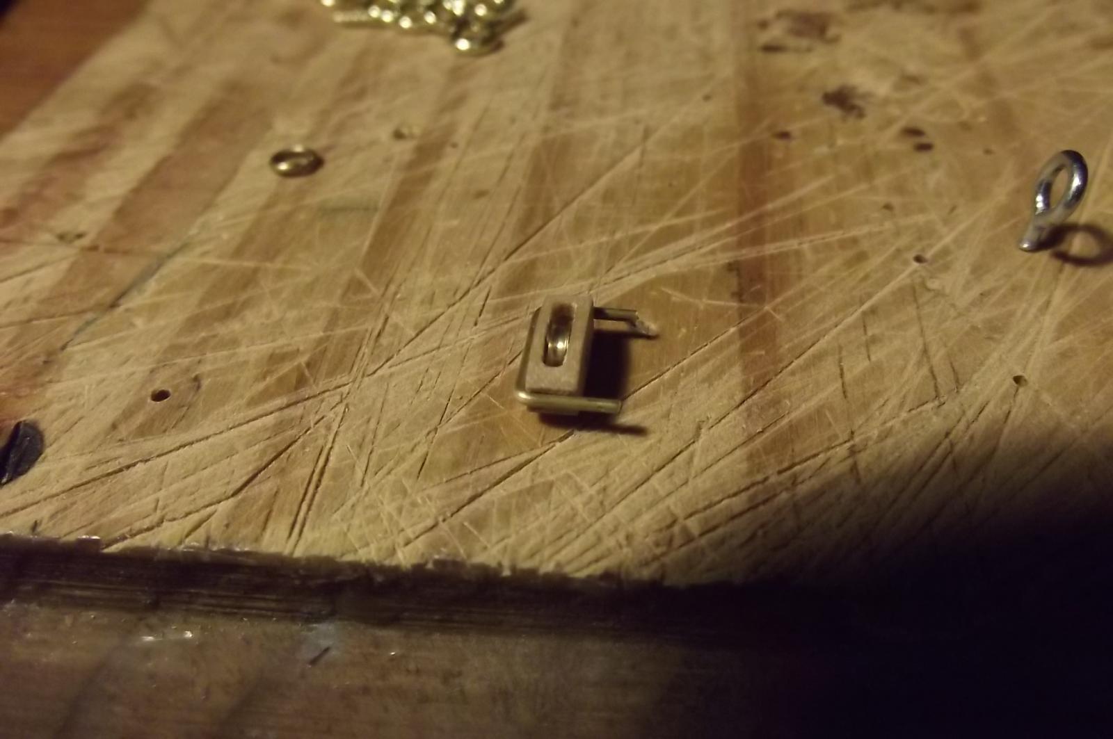
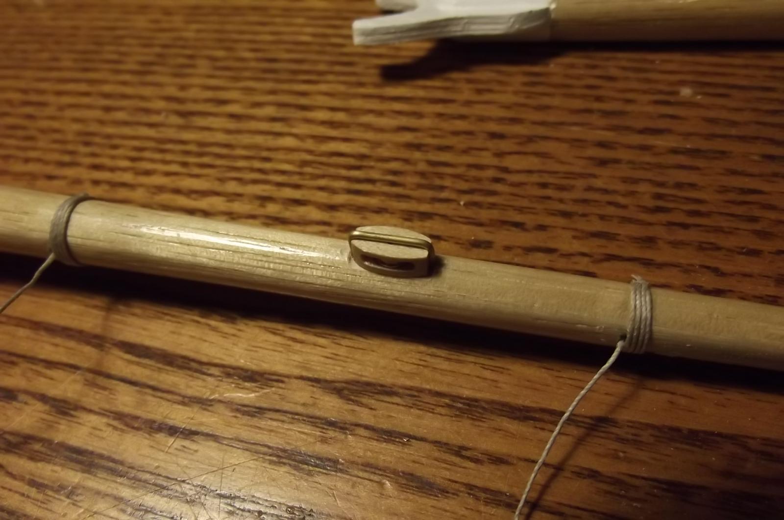
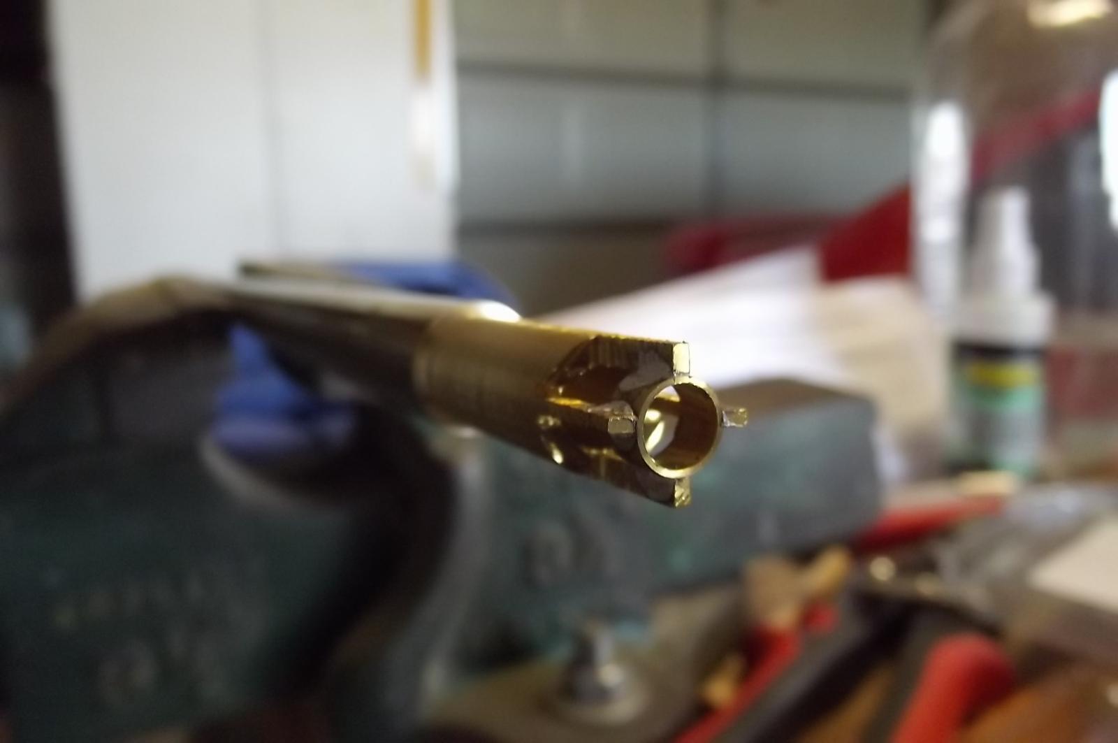
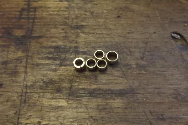
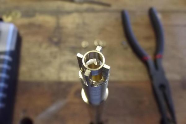
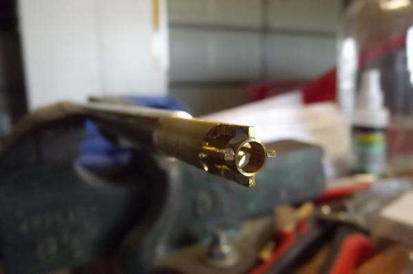
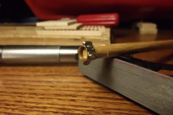
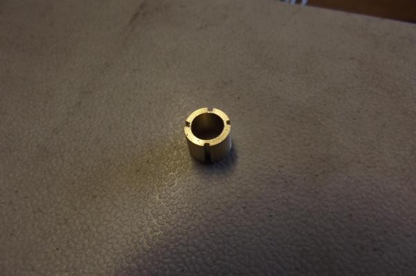
I got some more brass today and I am enjoying working with it. So this is how I made the collars, I have not made a kit for a few years and since this isn't a kit I have nothing to remind me of the correct names. First pic shows one of the original collars with the grooves cut into it to accept the eyes and hold them while soldering. This didn't work because they were too unstable and the eyes kept falling away so I came up with a better way which needed a larger diameter brass. It also meant that because I wasn't cutting grooves into the collar I could make them thinner as you can see in the pic. Three smaller ones for the top masts and one larger one for the bow sprit jib boom. So, first step, in the lathe drill out to 5.5mm internal diameter then turn down to 6.5mm external diameter to get the collar, then using larger stock drill it to 6.5mm internal diameter and turn down to 10.5mm external diameter thus leaving a cylinder with walls 2mm thick. Then remove the stock from the lathe and secure it in the vice with the machined end facing up and carefully cut down into it with a hacksaw twice, once either side of centre with approx 1.5mm between the two cuts then rotate the piece 90degrees and repeat. Once the four vertical cuts have been done cut horizontally into the piece which is to be removed, just a bit, then using long nosed pliers take hold of the scrap and bend it outward til it breaks off leaving this. insert centre section and solder The reason the "legs" are longer than they need to be is to stop the heat from the gas torch going into the stock too quickly which would make soldering difficult because I would have had to apply much more heat. Note in the above pic the bright blue part of the flame, the very tip of that is the hottest part of the flame so you want that to be just touching the job as you heat it. Now for those who think soldering is difficult and needs special fluxes etc, this really is not the case. I am using 40/60 resin cored solder. It is stonger than the normal 60/40, ie 60% lead and 40% tin and requires more heat but not so much as to need special equipment. I just use a hand held butane torch. The secret to successful soldering is cleanliness. All surfaces here were freshly machined without any cutting lubricants and I kept handling to a minimum to avoid contamination from touching. Heat the opposite side to that being soldered where possible as solder runs to the heat. Apply heat for a little while then remove the flame - VERY IMPORTANT - if you leave the flame there it will burn the resin which polutes the surface. After removing the flame touch the solder to the joint and see if it melts easily, if so only a little is required and it should run into the joint, you may need to apply a little more heat to encourage it to run. I just worked my way around the piece doing each side of the tabs and when done I applied the flame directly to the solder for just long enough to melt it and then gently ran an old paint brush over it quickly to remove the excess solder. Molten solder will splatter so be careful where you do it. A bit of a sand with the dremel and Robert's your mother's brother. I still need to drill the holes. A little bit more brass work


-
I have had a very frustrating day of ship building. I am trying to make the eye collars for the bowsprit and top masts but the mill bits I have are no use in this application so I decided to turn the collars to size then slit them using the fine cutting blade for the dremel in the mill as a slot cutter. The idea being that I could cut oversized eye pieces and stand them all up located in the slots and solder with a gas torch but even the light touch of the melting solder proved to destabilise the whole thing so it was a write off. I ended up turning the collar first and centre drilling it to the size to fit the timber, the external diameter is approx an extra 2mm to give a 1mm wall to the collar then machining the eyes in a way that is too hard to understand from text so when I do the next ones I will take pics to show how I did it. I need to get a larger diameter brass first though.


-
Yes John, sometimes when I am stalled trying to work out how to do something I just get stuck into part of the job and it all seems to just fall into place. Robbyn there are smaller hobby lathe/mills around which may be better suited to fine modelling, it depends on what you see yourself making with it, but it is a brilliant thing to have, having said that I still taper my masts etc with a plane and sand paper. Steve
-
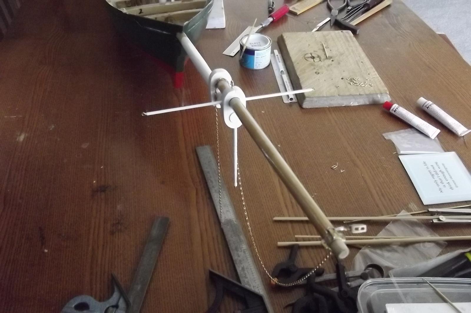
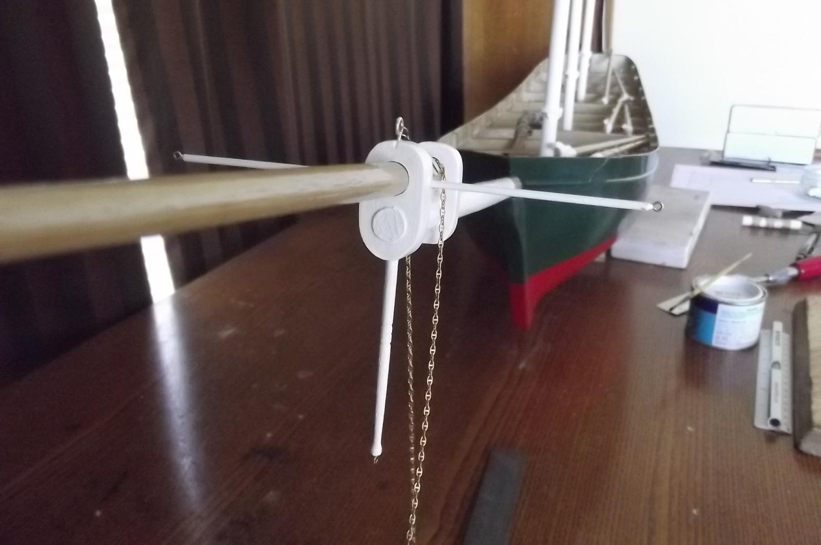
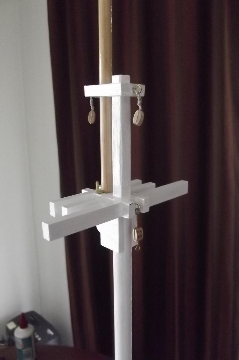
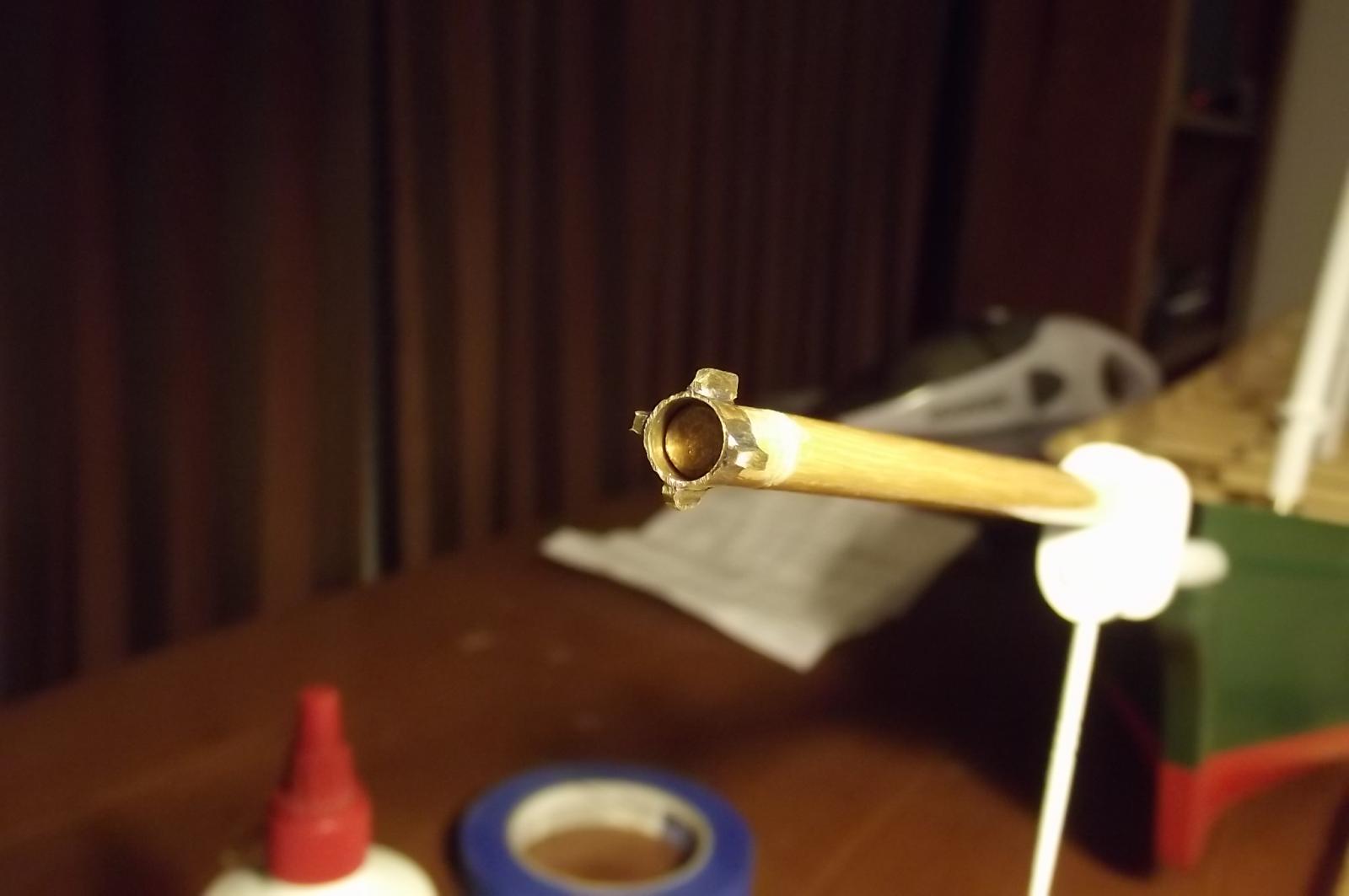
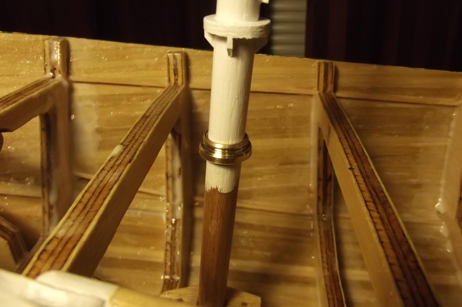
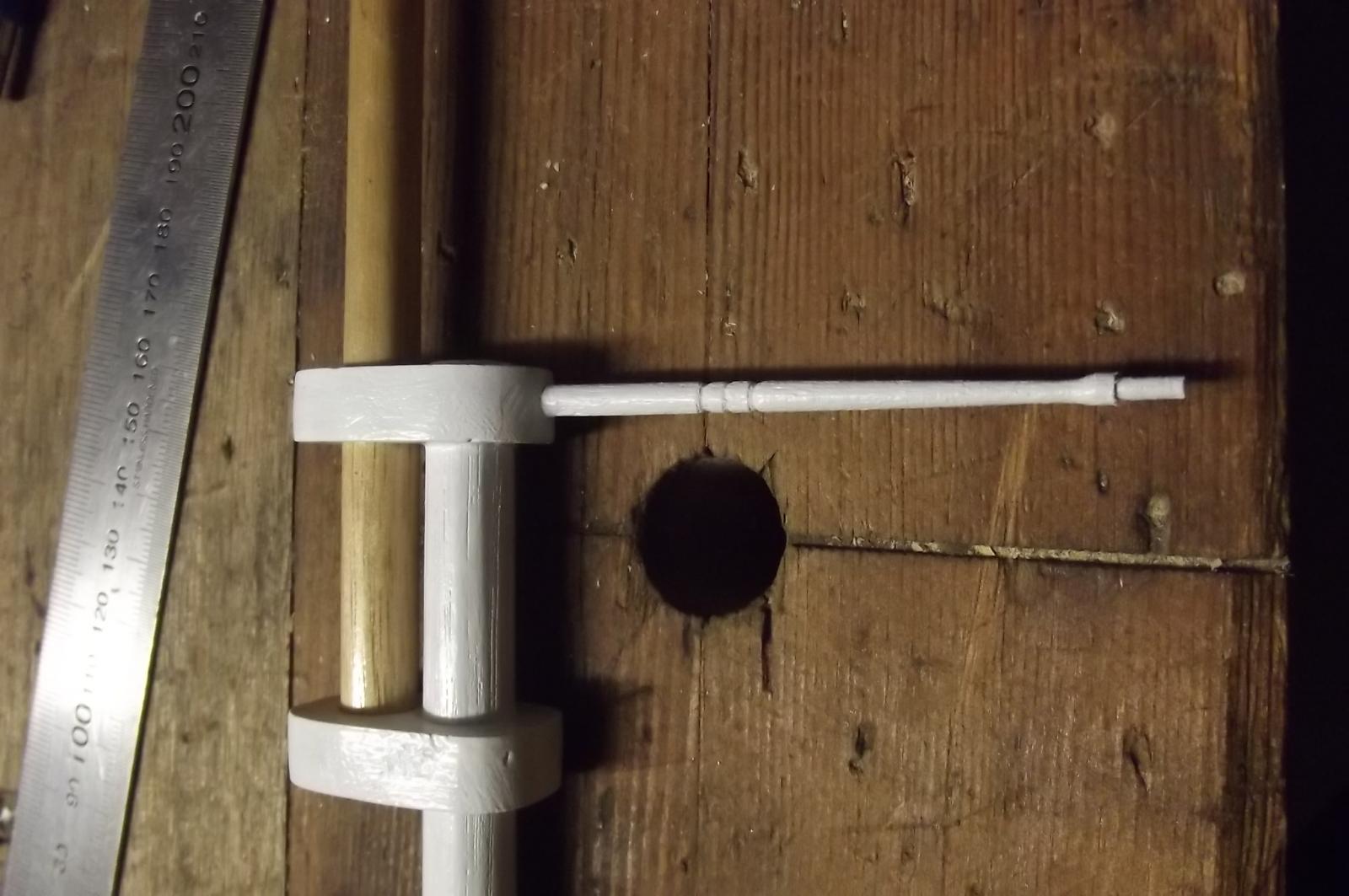
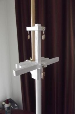
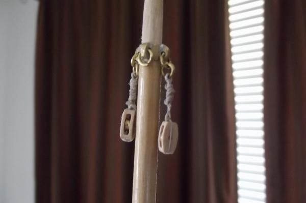
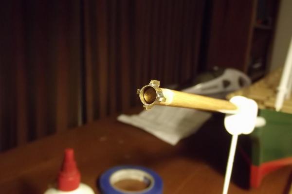
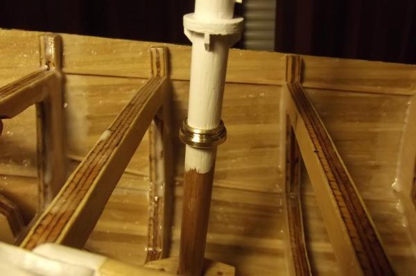
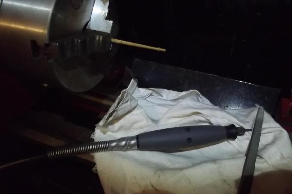
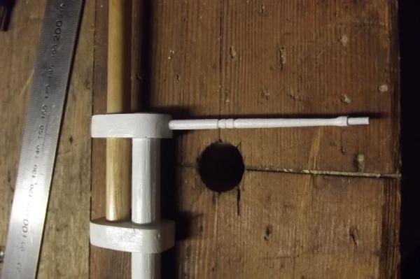
OK Robbyn, and Jim Lad. I have got off my design chair and done a little work today, just for you The first pic is a bit out of focus but you can see well enough the pins I have installed to locate the top masts in the raised position. Then I made the dolphin striker in the lathe, this is a very delicate operation because the thin piece of timber is so easy to break. First I gently turned the end down to 2mm diameter to accept the rigging hardware that I will make soon. Then using the Dremel and a bur bit while turning the piece I made the taper roughly. Then I used sandpaper wrapped around a piece of flat timber to smooth out and complete the taper. This whole process was done using my finger against the opposite side of the work as a sort of travelling steady to stop it from breaking. Then I used a triangular file to work the grooves into it. Dolphin striker fitted and first coat of paint.
-
That's OK Robbyn, keep pushing, the new job and extreme heat we are experiencing are combining to knock the wind out of my sails on this build. There are lots of little things that can be done and I am being a bit slack, days and days of scouring the 'net to find parts have left me a bit burned out too.
-
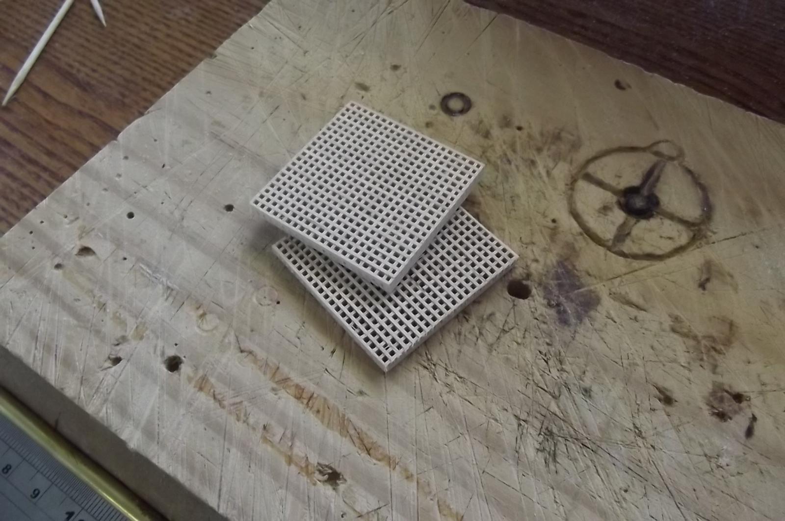
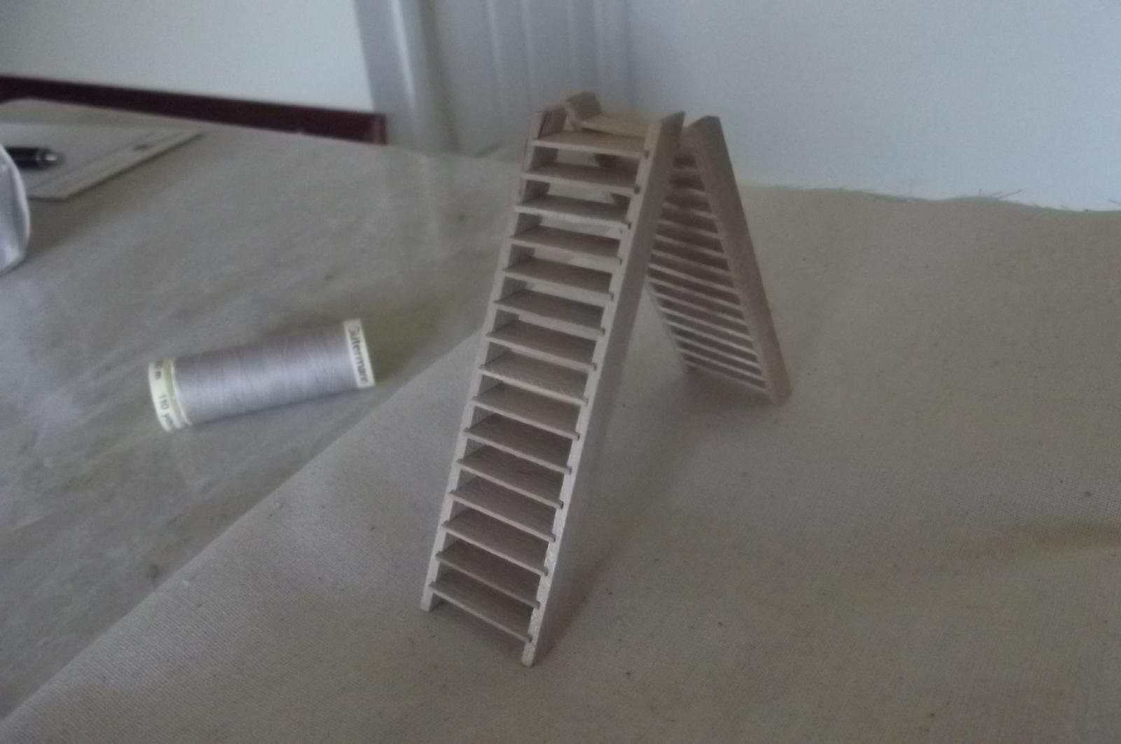
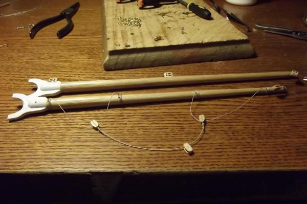
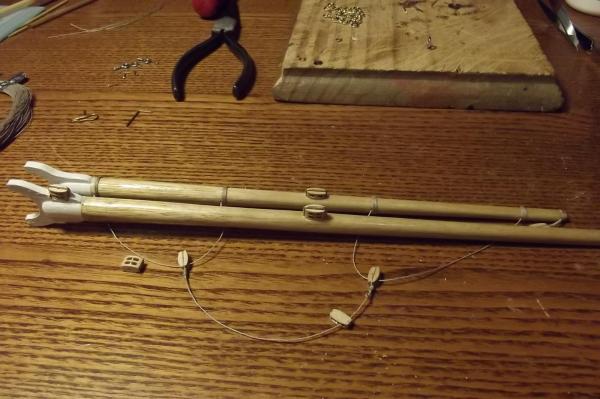
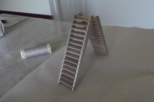
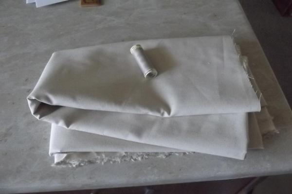
Hmmmmmmmmmmm, I'll try not to be too technical then, you see the hypotenuse of the clew on the fore top stays'l is exponetially influenced by the amout of rum that is gone, why's the rum always gone? Seriously though, while the maritime engineers ague between himself as to which is the best way to effect certain applications of force and leverage and the procurement officer is frantically trying to fullfil the engineers requests the shipwrights have been stood down. There are some things that lie where they left them like the almost finished grates, they just need to be cut to size when the helm is in place. The stairs which are waiting to be cut to size to provide safe access and egress to the quarter deck and fo'csle. A bunch of blocks...... A whole lot of plumbing, the running rigging will run in pipes below decks so I have a handful of 5/32 round brass tube which suits the K&S bender and one length of 3/16 tube which is a lovely fit over the 5/32 and will be cut into short lengths and used as couplings where needed and soldered into place. The sails have also arrived, in kit form! This will test my feminine side, I have mums old sewing machine and a head full of half knowledge I gathered while married, my ex made some very nice quilts etc. After a lot of web searching I think I have the sail winch servos on their way to me, they are all 6 turn servos but can be set to exactly how far I want each one to turn so I won't have to turn bespoke drums for each of them, I will still need to turn the complex drum for the stays'ls though. I will however need to redesign my aft deckhouse layout a bit but no biggie. On an unrelated note, this was a little close to home as they say, glad they got on top of it very quickly.


-
The lengths we will go to............. I do admire the way you think though, if it won't fit the bottle make the bottle fit the model. It should be worth it. Steve
-
Thanks Bob, I get the feeling we have a simmilar view to things like this. Don't get too anxious to see her under sail, there is a long way to go yet. As I said before, if you see me doing something that really won't work then by all means say so. All the tips and advice I have been given have been very helpful and having you, Floyd and Jerry along for the ride has really made a difference. I like to do it my way but I'm not stupid so I take all suggestions on board and process them. Steve
-
I've just been through this whole build thread, must say I'm impressed. Very nice work Michael. I find it particularly useful as a practicum for utilising the lathe/mill, mine is not of the quality of yours and I don't have many tools etc for it but seeing what you can do is really getting me thinking. Steve
-
I have added up the rigging required and am looking at approx 76metres. Sanding :- 25mtr Running :- 42mtr Sails :- 9mtr The run for raising and lowering the fore top stays'l will be the longest at approx 3mtr, definately can't have any stretch in the lines.
-
Ahh this is because I think outside the square. Because I build from complete scratch, ie no previous knowledge and no-one to learn from, I do it with a completely open mind. I thought all this out long before my first post so while people on here influence the build and give good ideas to make things better and easier the bones and core controls of her are always my way. Putting the servos up in the deck houses has a few benefits. They are easier to get to. They are high enough that a sealed radio box is not required because if water ever gets to them I will have bigger worries than fried servos as she will be on her way to the bottom. The deck will be able to be permanently attached with below deck access via cargo hatch to the only things down there, the motors and battery. Floyd told me about a kit schooner of the same size which I posted a link to a while back, she is lousy for scale appearance and is really designed to look good sailing at a distance, the point is she weighs in at 2.7kg wet and mine will be 5.7kg wet so having a few servos up at deck level will not be a problem for my schooner. I am a problem solver and this is why I am building this, to give myself problems to solve. Others build yachts to do club events or tall ships to sail but I am building a working model that will sail, if you see the difference. I'm about making a working machine. She may not sail as well as others but that isn't why I am building her. Early in this thread you see a pic of the back of my Land Rover with an r/c one inside. It was the same thing, I got the body then scratch built the rest, from the hand made aluminiun chassis to all the suspension linkages, bull bar etc. All scaled off my 1:1 in that case and it drives like the 1:1 as a result. Others don't.
-
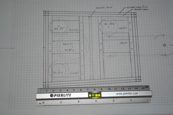
This is the big planning stage, making sure I get all the controls right. I have worked out which types of servos I need for all but the stays'l sheets but that will be in the fore deck house. I have worked out the aft deck house and will make it as inner walls that are part of the ship and then the deck house will fit snuggly over it forming a lid for the radio conpartment. The servos will screw down to beams fitted at deck level, the outer beams will be glued to the fore and aft walls of the deck house while the inner beams, along with the sheave axle will be srewed down so they are removable to allow greater acces below the deckhouse. All the winch servos will only have one in and one out line with the exception of the stays'l winch which will have three in and three out. This is because each stays'l has a different length of pull to raise and lower it so there will be three different diameter drums. The lines will go over sheaves turned from either delrin or brass which will be spaced along the sheave axle, because the stays'l winch will have three lots of lines, one above the other, I will turn larger diameter sheaves to keep the feed level with each drum. The lines will then go below to spring tensioned individual blocks where they will turn forward into tubes that will guide them to their respective destinations. Well, that's the plan.................