


Bob Cleek
-
Posts
3,374 -
Joined
-
Last visited
Content Type
Profiles
Forums
Gallery
Events
Everything posted by Bob Cleek
-
Aside from a few exceptions such as Byrnes Model Machines, Syren "Rope Rocket" and Domanoff's rope-making machines, Sherline and Taig mini lathes and mini milling machines, which are probably the best of their type available, you will generally find that tools made for sale to the "home hobbyist" can often cost more for a much lower quality product than the same tool purchased from a source catering to a professional clientele in an allied craft or trade. For example, the Foredom flex-shaft rotary tools or any of the slow, belt driven dental engines (now used for fabricating dental appliances in dental labs and not for drilling teeth, thank God!) and their handpieces will do a much better job than under-powered high-speed / low-torque Dremel or Proxxon Mototools and the like. I don't suppose Proxxon tools are substandard for what they are and they do have their fans (particularly in parts of the world where nothing else is available,) but they frequently strike me as being overly specialized in some instances and "more sizzle than steak." (Who needs a 1/4" hand held belt sander?) Lathes and milling machines are a separate category, but one should be aware that "hobby" retailers such as MicroMark, Model Expo, and Proxxon will frequently sell much higher priced "house branded" versions of tools which can be obtained from other sources at lower prices. The Chinese manufacture identical power tools such as mini lathes, mini milling machines, and rotary tools, etc., and wholesale these at varying prices based on the degree of fit, finish, and quality control, providing their wholesale customers with custom paint colors and branding. Grizzly is one US retailer that sells higher quality Chinese-built power tools at a somewhat higher price than the same tool will sell for at "Horror Fright," but the Grizzly tool will have a better fit and finish and have been fettled, tuned, and tested, while the Harbor Freight version will quite possibly have casting sand in the cosmoline grease it was coated in before it was shipped in from China. It's best to do what research you can on YouTube watching "unboxing" and "review" videos before you pull the pin and buy any Chinese made power tool. The bottom line is that you will not go too far wrong keeping in mind that "you get what you pay for." You will almost certainly find that the highest quality tools will be found in the professional suppliers' catalogs for the various trades and professions. For example, look for hand tools in commercial jewelry supply house catalogs and medical instrument supply house catalogs. Keep in mind, however, that it is possible to spend too much in the professional catalogs. A lower quality Pakistani surgical or dental instrument will often be entirely adequate for modeling work, while the same instrument made by a top of the line US or European manufacturer may exceed the quality requirements of a ship modeler.
-
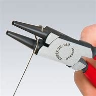
I have never seen "square mandrels" like those. It would seem that anyone requiring one would simply cut a stick of wood if they needed one or use a pliers suitable for bending the shape if need be. The mandrels pictured are somewhat odd, as well. They are probably intended for use by jewelry makers, but jeweler's or orthodontist's wire-forming pliers pliers are far more useful tools for ship modeling. Wire rings are easily formed in exact sizes by wrapping the wire around the smooth end of a suitably-sized drill bit. A standard set of drill bits will provide a wide range of sizes. After wrapping around the shaft of the bit, the wire can be cut free with a diagonal cutting pliers and slid off the bit shaft. Jeweler's wire forming pliers are made in a variety of sizes, shapes, and styles and are quite reasonably priced. They can be found on eBay and in jewelry supply house and orthodontic instrument catalogs. See: Amazon.com : forming pliers
-
Yes, it's the same stuff. While different grades of quality may still exist as in the olden days ("Stockholm" being "finestkind,") pine tar is still pine tar. It's readily available online and its primary modern-day uses are still as a wood and natural fiber rope preservative, especially in traditional maritime applications, as an ingredient in certain soaps, and in veterinary, and even human, medicine, as a topical antiseptic for the treatment of dermatological conditions. Notably, due to pine tar's long-lasting stickiness, it is also applied to wooden handles, baseball bats being a famous example, to improve a user's grip. I can't imagine anyone using it on a ship model, though. Aside from its agreeable aroma, it's a rather nasty, sticky substance of extremely dark brown color that gets all over everything and is slow to polymerize, so it stays sticky for a long while. The British sailors were called "tars" because they became covered with the icky stuff in the course of their shipboard duties. Critically, in the Age of Sail, pine tar was an essential naval store, access to which determined the effectiveness of European navies, and the Swedish crown's monopoly on the production of the largest quantity of the highest quality pine tar gave them advantageous leverage in European international relations until the British Admiralty discovered that the abundant pine forests of their American colony of North Carolina produced pine tar of equal or better quality than the "Stockholm tar" the Swedes made from their Baltic pines. Once British pine tar production ramped up in North Carolina, her residents became known as "Tar Heels," and have been ever since, because once you are around the stuff any amount of time, you will get it on your feet and track the stuff all over the place.  Applying thinned pine tar to your model ship rigging will probably give your model and anywhere it is displayed a highly authentic "yarr!" aroma for a good long while, but by the time it's finished both you and your model will likely be stained dark brown to black from stem to stern, just like its prototype was. Pine tar on a baseball bat. 
-
From all recent reports, linen thread of sufficient quality for rigging line material has become extremely difficult to reliably source in recent times. There is reportedly some NOS (“new, old stock”) linen thread offered on eBay, but the size and quality are “catch as catch can.” Modelers currently using it are probably using “stashes” of linen thread they purchased ages ago. A Google search will provide a number of retailers offering linen thread, but much of what they are offering is specialty material, such as heavy pre-waxed thread for leather working or bookbinding. Other online retailers don’t indicate thread size. When just checking now, I was surprised to see that Guttermann offers a waxed linen thread. You may want to research what Guttermann has to offer in terms of linen thread in their line. See: https://www.amazon.com/Gutermann-Waxed-Strong-Sewing-Thread/dp/B019HRLE1A/ref=asc_df_B019HRLE1A&mcid=c6045ff257ee34edb6ad3599ab063d4d?tag=bingshoppinga-20&linkCode=df0&hvadid=80058380336600&hvnetw=o&hvqmt=e&hvbmt=be&hvdev=c&hvlocint=&hvlocphy=&hvtargid=pla-4583657849049970&psc=1&msclkid=998cf52caad914ea2e15909d34b77174 I expect that anyone who has a lead on where suitable linen thread can be purchased will share it in due course. Yes, shellac applied to thread will make the thread stiff once the alcohol solvent evaporates, which it does quickly. This is one of its main advantages when used as a rigging material. A drop will cement a knot and prevent its accidental untying when the “bitter end” is cut short. A bit of alcohol will soften it so a shellacked knot can be untied if necessary. When applied to a slack line or to a coil of line, the line can be formed as desired to shape the coil or form a catenary in a slack line. As the alcohol evaporates, the degree of stiffening increases, so it can be easily “worked” to a desired shape. We’re talking about applying thinned shellac of two or three pound cut (as it is diluted when sold premixed in cans.) Repeated applications of shellac on top of previous dried applications will build up a usually undesirable thick coating with a gloss finish. When only one or two applications of thinned shellac are applied, these will soak into the surface and be invisible when dry.
-
Current post on the Model Machines website: We are in the process of personal and corporate recovery after the loss of Jim ... We will not be accepting orders for machines until further notice, but you may still order accessories. We need to complete an inventory and business reorganization, which we hope to accomplish in the next few weeks. Thank you for your understanding and continued support ... Donna Byrnes Word on the MSW forum also reported a conversation with Donna Byrnes confirming they would be back to filling orders shortly. Keep an eye on their website for a formal announcement.
-
Consider wrapping it on a larger diameter cylindrical shapes. This avoids the line taking a set at the sharp edges when wrapped around square shapes and a curved shape tends to keep the tension in the line equally distributed while stored for long periods. I've used empty cans sometimes as big around as coffee cans. Tape one end of the line to the can and wrap it neatly without overlaps and then tape the other end to the can. You can put a fair amount on a single can and see at a glance how much you have if you don't overlap the turns on top of each other. Even smaller cylindrical shapes work fine. Empty toilet paper rolls work really well. They are easy to write on to note the size of the line wrapped on them and easier to store than coffee cans. (If you have a lady or two living in your home, there should never be any shortage of empty toilet paper rolls. When I once worked part-time as a school janitor, we used to figure as a rule of thumb a ratio of three to one between the girls' and the boys' lavatories when filling the toilet paper dispensers and despite decades of living with a wife and three daughters, I've never unraveled the mystery of why this is so, but it seems to be one of life's immutable truths. ) I've also seen some guys who have used longer cylinders such as empty paper towel rolls mounted on a row of horizontal spindles in the same manner as a single paper towel roll holder. From this arrangement, they can at a glance choose which type of line in their stock supply they wish to use, measure off a length and cut it from the roll.
-
I was thinking the same thing. I agree completely with Jaager's sage advice. We are kindred spirits when it comes to using premixed canned 2 or 3 pound cut clear shellac for sealing wood, cementing knots, shaping line into coils and catenaries, making flags look like they are flying, shaping cardstock, and when thickened, even as an adhesive under certain circumstances. (In fact, they also use thinned shellac in food processing to make jellybeans and apples and citrus fruit shiny.) I don't think we are necessarily in the majority of modelers who use shellac for so many things, but I'd expect many of the "geriatric set" do, having discovered that nobody's really come up with a better material to use for any and all of these purposes. And, as an additional benefit, shellac is easily removed (and rigging knots requiring adjustment easily untied) by simply wiping it off with an alcohol-soaked cotton swab or piece of cloth, since the hardened shellac immediately dissolves in contact with alcohol, the all-purpose solvent used to thicken and thin shellac and easily clean up after use. I think that a "sanding sealer" is somewhat of an oxymoron, given that there isn't much point in sealing a surface if you are going to sand it, since that sanding is going to remove some, if not all, of the sealer which doesn't soak into any wood species very deeply (and practically not at all on the flat of the grain.) The only application I can think of which calls for sealing a surface before sanding, and then only at the very end of the surface preparation exercise, is to "harden" a soft wood such as basswood at the last step and apply a very fine light sanding to remove the "fuzz" from the surface of woods that tend to "fuzz" when sanded. Thinned shellac, which penetrates the word surface as far as anything does, and that's not much, binds the fine wood fibers together and permits a fine sanding that doesn't raise "fuzz." In doing so, you have to be careful not to sand through the sealer coat to bare wood. Not only would this wood be unsealed if the sealer-permeated wood "crust" is sanded through, but also, subsequent coats of paint will soak into the bare wood, resulting in a painted surface which betrays this fact. In the case of gloss finishes, the unsealed (unprimed) spots will show as flat (matte), instead of gloss to one degree or another. The inexperienced will often apply additional finish paint before the first coat is uniformly dry in an attempt to "gloss up" such flat spots and, as more experienced painters know from hard experience, "going over" anything applied wet before it dries thoroughly rarely comes to any good end. To cover a base that may have been missed, I realize that many, rightly or wrongly, refer to "plastering" a piece (usually a hull) with, literally, plaster or drywall "mud," Bondo, (tm)" epoxy putty, or "fairing paste" made up of epoxy resin and various proprietary "sanding (or "fairing," or "surfacing") additives (e.g., "micro balloons.") after assembly of the wooden substrate and then "hogging off" as much "surfacing" material as is necessary to fair the piece and leave the remainder of the surfacing material to fill the cracks, craters, and even canyons on the original as-built surface. In a perfect world, everybody's planking jobs would look like those of we-know-who here on MSW, but for most of us, that's not going to happen in our lifetimes and "filling", or "fairing" is a routine task which is of great value in covering a multitude of errors. It's essential to obtaining a "smooth-as-a-baby's-bottom" finish if open grain woods are used. (All those whose drill instructor used a different simile to describe for this desired level of smoothness, raise your hands. ) There's a use for shellac here, as well. There are many products marketed for filling grain and minor surface imperfections. They are usually overpriced and of varying degrees of usefulness. There is a very simple traditional and certainly archival method of filling minor surface imperfections using shellac. In the manner similar to "French polishing," when a surface is sanded sufficiently fair, it can thereafter be rubbed with a felt and/or cloth pad containing an oil (e.g. linseed oil, raw or boiled,) and pumice (powdered volcanic glass,) This process will cause the pumice to abrade the sealed shellack-sealed surface while at the same time filling the open pores of the wood grain with a slurry of shellac sealer and pumice, which being glass, becomes transparent. Repeating this process as with French polishing, will result in a perfectly smooth surface. If one wishes, the same can be done using fine grit "wet or dry" sandpaper. See: Wikipedia on "French polish" for an explanation of how it's done. It isn't rocket science and the learning curve is practically a flat line, but, unfortuntely, it's not about skill as much as it is perseverance. French polish - Wikipedia There's also a ton of YouTube videos on it. It's a good, easy to learn skill to have in your tool box. If we are talking about a lot of filling needing to be done, sealing with thinned shellac may be advisable before the fairing material is applied. The shellac provides a stable base that is more effective for many putties and plasters adhering to than bare wood. This initial sealing before filling is highly advisable with "wet" materials that contain water which will more readily be absorbed by bare wood which will result in a "cure" of the surfacing material and a "damp" subsurface where the wood and plaster or other surfacing material meet due to water absorption from the surfacing material. This may result in shrinkage of the surfacing material requiring multiple applications, weak adhesion, especially on thickly applied areas, or even mold and other unwanted issues. Surfacing materials with resinous binders such as Bondo and epoxy adhesive resin with "sanding additives," are not prone to having their solvents "sucked out of them" by their contact with bare wood, as occurs with the water in surfacing materials containing water. One parenthetical caveat: Many are familiar with automotive body and fender "fillers," such as Bondo. Bondo and however many of its similarly compounded competitors is designed to adhere to metal, not wood regardless how well it might do so in any event, or whatever the instructions on the can may state or imply. Bondo is hygroscopic. This means that when water "seeks its lowest level," Bondo is part of that equation. "Bondo" attracts and holds, which is to say "absorbs," water from the air. If the moisture content of cured "Bondo" is lower than the ambient air, the "Bondo" will absorb the difference until equilibrium is reached between the drier "Bondo" and humid air. Similarly, if "Bondo" is applied to wood, and the moisture content of the wood is lower than that of the Bondo," the wood will suck the moisture out of the "Bondo" until the wood's moisture content reaches equilibrium with the "Bondo" and, in turn, the ambient air. Now, for models that will live in glass cases in cozy, climate-controlled homes, there may be little point in worrying about this bit of physics (or is it chemistry, or both?) There may just not be that much moisture involved in the environment in which the model will exist to cause any problem at all. However, in the real-life full-scale world of wooden ships and boats, Bondo and other polyester resins are frowned upon because in the marine environment there is certainly enough ambient moisture around on a regular basis to cause the wood beneath Bondo patches to become wet, soft, and infected with fungal decay in such a way that the Bondo no longer holds very aggressively to the wood and, eventually, the wood decays. It is not likely many of our models will survive much longer than any life-in-being on the day we die. We will all eventually become that grandparent or great-grandparent or other relative who "died before I was born" and who "I never knew." Unless we were royalty, National Enquirer level celebrities, or left them a large trust fund with a specific endowment to fund the preservation of our model collections, the majority of our descendants who are born after we have died aren't going to be the slightest bit interested in preserving our handiwork. (Indeed, I personally know at least one modeler's spouse who's highly likely to dispose of all her late husband's "damned boat junk" as soon as the opportunity presents itself! ) However, maybe... just maybe, one of our models survives, by virtue or happenstance, and if that happens, I've come to conclude that using state of the art archival materials and practices whenever possible is a good thing because, if and when that ever happens, it may well be in large measure because it has simply lasted longer than the rest. If you sense a bit of the Luddite in all this, I'll plead guilty. Since this is all "mature technology," I have to say it's all been thoroughly "Beta-tested." Using lasting materials makes sense because so much time is invested in a model that lasting materials are well-warranted. In closing, let me add, "avoid water-based materials. The water soaks into the wood and it raises the grain no matter what you do. Always seal with a good sealer. Shellac is one of the best natural, non-toxic sealers around and one of the less expensive. Stick to tubed artist's oils, linseed oil, turpentine, and Japan drier to mix your own colors or at least to condition unmixed colors. You'll save money and your work will endure if at all possible. Build using safe, "organic" materials and avoid becoming too dependent upon the synthetic chemical industry.
-
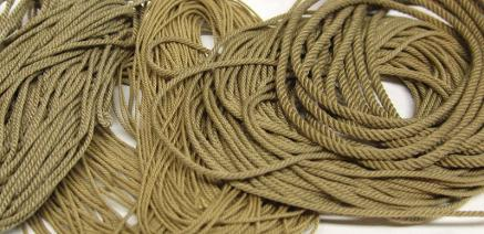
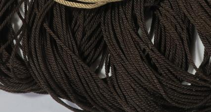
Well, actually, your "bees wax" looks more like paraffin wax, the stuff they use for pouring over the top a jam and jelly in canning jars. There is a white beeswax, but I've never seen it in the flesh, as it were. All the beeswax I've ever seen is yellowish brown. Using beeswax on model ship rigging is questioned these days due to concern regarding the acidity of it contributing to the deterioration of models over time and beeswax's propensity for collecting dust. The general opinion among professional museum curators seems to be that microcrystalline "conservator's wax" is the better option. Many still use beeswax, though. You might find this thread of interest: Speaking of thread, the recent acceptance of Dacron and Dacron-blend thread for model ship rigging cordage, which has been "blessed" as acceptably archival for museum use by some of the major museums, has gone a long way to solve the problem of "the fuzzies." Formerly, line had to be "flamed" (passed through a flame) to remove this fuzz and wax used to keep it from reappearing, but the synthetic thread cordage doesn't seem to have the problem, the synthetic fibers being much longer than the natural ones. (Finally! No split ends! ) I know you are a way along with some of your rigging, but what they have provided in the kit is really junk and way oversized and out of scale from all appearances. It's your call, but before you start getting into the rigging with a vengeance, you may want to consider getting into spinning your own properly scaled rope or purchasing aftermarket rope from Syren Ship Model Company (an MSW sponsor.) Syren rope has no fuzz and doesn't unravel. It's easily "stiffened" and knots secured with a touch of thinned PVA or clear shellac. (The shellac is easier to remove with alcohol if you want to undo a knot if a mistake is made or an adjustment necessary.) (See the pictures and URL below.) This is what correctly made scale rope should look like in the correct sizes. It is also so much easier to work with. When I looked at what they gave you for gun tackle line, I thought, "Oh, the poor guy!" You did a lot better job with what you had to work with than I ever could, but how you got that loose, oversized stuff through your blocks is beyond me! Your rigging skills look fine. It's the quality of the line you are using that's holding you back from achieving a much better result and with a lot less work! Poor rigging line is a common frustrating defect with kits. If you've decided to go with photoetched detail (finestkind!) you may as well match that quality with good rigging line. In for a penny, in for a pound. See: Scale Miniature rope for Rigging Ship Models - Hand made rigging line for ship model builders (syrenshipmodelcompany.com)


-
Tiny "precision" drill press
Bob Cleek replied to Ron Burns's topic in Modeling tools and Workshop Equipment
Looking forward to your review! -
Tiny "precision" drill press
Bob Cleek replied to Ron Burns's topic in Modeling tools and Workshop Equipment
I came across this mini drill press the other day, It isn't as elegant looking as the one above, but it's rated at 120W/450 RPM as compared to the one above at 30W/4800 RPM, has a drilling depth (quill stroke) of 42mm (1.65") versus 13mm on the above one, and it has an adjustable depth stop on it. $67.00 (w/ free shipping from Los Angeles) Mini Bench Drill Press Precision Table Milling Machine Portable Driller DIY 120W | eBay I would suggest that anybody who is thinking of a mini drill press and an x/y table might want to consider Vanda Lay Industries' offerings. They started with a CNC'd aluminum mini drill press that holds a Dremel moto-tool (or any other rotary tool including the 1" Foredom flex shaft handpieces (which I'd consider a much better alternative than the Dremel) and their "system" has grown now to include a milling machine that doubles as a drill press and has x, y, and z tables, as well as a mini lathe option. I have their drill press with a Dremel in it and it is a high-quality piece of equipment, perhaps more than the Dremel moto-tool deserves. The Foredom handpieces would provide more accuracy and torque at lower speeds than the Dremel. See: HOME (vanda-layindustries.com)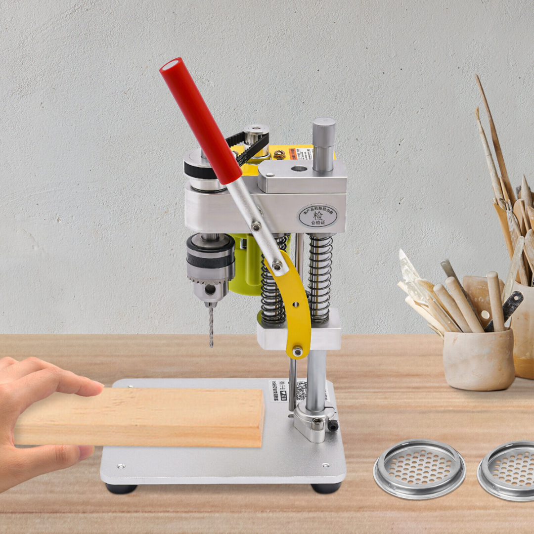
-
Great job! An interesting vessel and a model that is truly a work of art. By that I mean that it's details, particularly the figures, convey a sense of warmth and charm, a sense of "life," if you will, that doesn't seem possible to achieve with our highly accurate, but, frankly, "lifeless and antiseptic," "as built" technical modeling masterpieces. This model demonstrates how a viewer can indeed be "drawn into the reality" of a ship; by viewing a model of it. This isn't a criticism of technical "as built" models at all. They are a different thing entirely and magnificent in their own right. This model, though, really exemplifies that quality that distinguishes art from craftsmanship in ship modeling, two equally respectable qualities, which I've tried with only limited success to explain to others from time to time. What I'm talking about here is exemplified by the photo below. Nobody who's ever been to sea can fail to recall the feeling of facing into the wind that this tableau conveys:

- 330 replies
-
- 11
-

-

-
Yes he is. An SL or DB (same thing, different model numbers.)
-
Pulled the Trigger == Lathe coming
Bob Cleek replied to kgstakes's topic in Modeling tools and Workshop Equipment
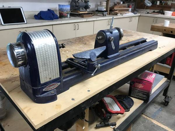
Being that a machinist's lathe is about the most versatile machine there is, there's a tremendous amount that can be learned about operating one. As a self-teaching lathe operator who has only scratched the surface of what can be known, the best advice anyone ever gave me about leaning to run my 12" Atlas-Craftsman lathe was to get a copy of The Manual of Lathe Operation & Machinists Tables published by the Atlas Press Co., maker of the Atlas-Craftsman lathes. It is not only specific to the Atlas-Craftsman lathes, but to all machinist's lathes in general and has all the information one could need. Fortunately, the 23rd Edition (which I think was the last) published in 1967 is available as a free PDF download from VintageMachinery.org. See: Atlas Press Co. - Publication Reprints - Manual of Lathe Operation & Machinists Tables (MOLO) 23rd Edition | VintageMachinery.org Just below the lower left hand corner of th picture of the front of the book ("Publication Preview") is a link: "View PDF" in blue printing. Click on that and the whole book should come up on your screen. It may take a few seconds because it's a long 273 page download. Scroll down to read it. There are also some excellent U.S. military training manuals which are available as free PDF's you can google up. I found those very helpful because the military does an excellent job of teaching the average idiot like me who knows nothing about a subject how to do highly technical things. -
In the United States, you have a 12" lathe. Hereabouts, lathes are described in terms of their "swing." "Swing" is the largest diameter that the lathe will hold and turn. It's not an exact measurement, but rather is usually rounded off to the nearest inch. On the other hand, if you were in the UK or Europe, lathes there are described in terms of their "centre height," this being the measurement between the ways and the center of the spindle or "half the swing." Your lathe is a 6" lathe on the other side of the Pond and a 12" lathe in the U.S. The babitt bearings on the Atlas 12" lathes have shims in place which are intended to be removed over time to compensate for bearing wear. Your lathe probably doesn't have enough "miles" on it to need the babbit bearings re-poured. There are Atlas 12" instruction manuals all over the internet that you should check out, including the manuals for the older machines. See: https://www.hobby-machinist.com/ They have an active forum section on the Atlas/Craftsman lathes and seem very helpful and welcoming to novice owners of these lathes. They also have an extensive library of manuals and parts diagrams in PDF format. (I believe you have to register to download them.) The Tubal Cain / Mr.Pete222 YouTube video I posted above in post #21 shows how to engage the back gear on the Atlas 12". Watch the video. The procedure is not particularly intuitive. Pay attention to all the cautions about setting pins in the headstock gearing and how easy it is to break them if you aren't careful which he mentions in that video as well. It bears mentioning that machinists' lathes are one of the most dangerous stationary power tools of all and should not be approached by anyone who has not at least thoroughly read the operator's manual for the particular lathe they are dealing with and familiarized themselves with its operation. We all have "oops moments" now and again. The problem with a machinists' lathe of any size is that just about any "oops moment" can risk the total destruction of the lathe or its operator! There are all sorts of copies of the manuals and parts lists for the Atlas Craftsman lathes. http://vintagemachinery.org is a valuable resource. They have an extensive collection of manuals in PDF format and, as far as I know, they are accessible for downloading and printing without cost. (Many of the internet manual services charge for manual downloads.) Here's the link to download the 1937 edition of the classic Atlas Manual of Lathe Operation. (A "bible" of the trade often referred to by its initials as "MOLO.") This book tells you how to operate and maintain your Atlas/Craftsman lathe. Please read it and consult it before you have another "oops moment!" http://www.vintagemachinery.org/pubs/51/18169.pdf Groups.io also has a specific Atlas/Craftsman lathe group that is worth checking out: https://groups.io/g/atlas-craftsman As mentioned, it is a 12" lathe here in the U.S. Atlas also made a small 6" lathe which is a different machine. It appears that you looked up the Morse taper sizes for an Atlas 6" lathe. The 12" inch lathe takes a #3 MT in the headstock and (I presume) a #2 in the tail stock. Watch the Tubal Cain video I posted above. He goes over the 12" headstock in detail. Staying clear of the chuck is a good thing! A smaller chuck provides more room to work closer to the chuck. That said, a smaller chuck is no substitute for being careful. If you are turning wood, you don't need a chuck at all. Simply using a drive spur and live center on a suitably sized MT post and you're good to go. Wood turning is done at relatively high speeds, and you are in contact with the workpiece through the cutting tool held in your hand. Far better to avoid a chuck in any event. Moreover, a proper wood lathe chuck is a different animal from a metal lathe chuck. The wood lathe chuck generally doesn't have protruding jaws like the metal lathe chucks do so there is much less risk of contact with spinning jaws. Certainly, you can use a metal lathe chuck for turning, but it's another example of not using the right tool for the job posing certain increased risks. Wood turning chuck: Spur drives and live center for wood turning: Using a machinist's lathe to turn wood can be done, but if you are going to do a lot of it, I would suggest you consider getting a dedicated wood turning lathe and leave your Atlas 12" for metal and plastics work. If one takes a pass on all the questionably necessary electronic bells and whistles, a wood turning lathe need not be expensive to acquire and there is much less need for tooling and accessories for a wood turning lathe, as well. A little Grizzly 8"X13" tabletop "pen turner" bench top wood lathe can be had for as little as $118 if you shop around online. 8" x 13" Variable-Speed Benchtop Wood Lathe at Grizzly.com A larger basic Grizzly 12"X18" variable speed benchtop wood lathe with drive spurs and live center can be had for less than $400 new. (For another $100, a 22" bed extension is available for it.) 10" x 18" Variable-Speed Benchtop Wood Lathe at Grizzly.com Then also, small wood lathes seem to be one of those items that people buy with grand intentions and then, for whatever reason, lose interest in it. There are lots of wood lathes for sale in the local online "garage sale" sites like Craigslist. A decent used wood lathe isn't hard to come by at all and most are very reasonably priced. The "bulletproof" full-size bench top 1950's cast iron Craftsman wood lathes are fairly plentiful and run around $100 to $300 with the sears motor. Again, in comparison to a machinists lathe, there's very little that a user can do to hurt a wood lathe. (Although the wood lathe can still do a pretty good job of hurting you!) Having a dedicated wood lathe would probably make your life a whole lot less complicated. 1950's cast iron wood turning lathe:


-
The early ones did. They were first made in the early 1930's and were in production into the late '70's or early '80's. While they remained the same basic machine, they evolved in various ways during the span of their production. I believe that only the early pre-War models had the poured babbit bearings. Thereafter, the headstock bearings were bronze Timkin roller bearings.
-
Agreed! A smaller lathe would be a more convenient option for doing a lot of small part modeling work, as I discussed in my post above, although the cost of buying and tooling up two different sized lathes which couldn't share at least some of their tooling may make a second lathe an unaffordable luxury. Unfortunately, in terms of the advantages of collets you mentioned, the 12" Atlas/Craftsman lathes do have a #3 Morse taper headstock spindle which of course will accept smaller MT sizes with an adapter sleeve, but the spindle won't handle anything larger than a 3AT collet or the equivalent in the collet chuck designed for it because the chuck draw bar that runs through the spindle is limited by the size of the spindle hole, so the far more common and much less expensive (for the "bargain models at least) 5C collets won't work in the 12" Atlas/Craftsman lathes. I suppose one could devise a collet chuck that screwed onto the spindle or could be mounted on a #3 or #2 MT, but if one were going to want to use a wide range of small diameter collets, my guess is that they could probably buy one of the Chinese made Sieg "7 bys" and a set of small Chinese made collets for it with the savings realized from not having to buy 3AT collets at $35 or $40 bucks a pop for the Atlas/Craftsman draw bar collet holder! Proprietary collets are very expensive. The Unimat has a screw-on collet chuck which takes hard to find collets. A "basic" set of perhaps a dozen collets and the chuck for the Unimat SL/DBs runs between $1,000 and $1,500 used on eBay if you can find one! I agree about turning wood on a metal working lathe. When I have occasion to do so, which isn't often, I wrap my Atlas/Craftsman (and my Unimat, for that matter) up tightly as you describes with aluminum foil and masking tape. I do the same when I am working with any sort of abrasives such as my tool post grinder. It's not a big job to "gift wrap" it, considering how much work it is to break it down for a thorough cleaning when it's full of solidly packed oil soaked sawdust!
-
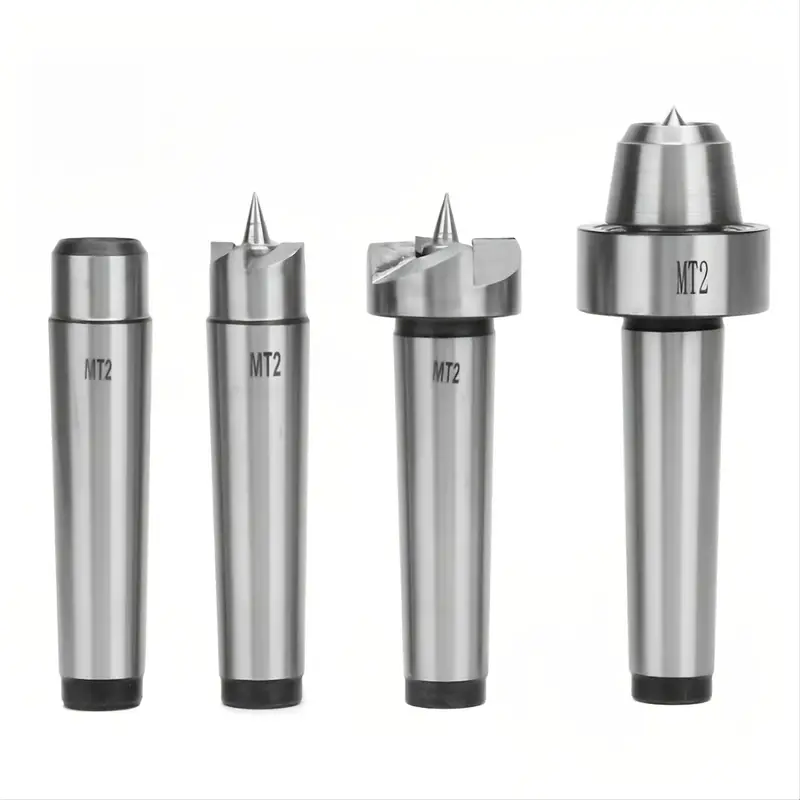
Note that Sherline is selling these chucks with back plates to fit Unimat DB/SL spindles that are 12mm in diameter x 1mm threading (or 14mm x 1mm for the Unimat 3) or "1/2" by 20 TPI for "old 6" Sears lathes." Sears sold lathes in a variety of sizes. The smallest was a 6" lathe (capable of handling material up to 6" in diameter,) there was a 9" model, and the 12" model made by Atlas. I've never seen a 6" Craftsman lathe in the flesh, but the 9" Craftsman lathe was a nice little lathe. Back in the day, "Craftsman" was Sears' middle of the line "house brand" for tools while "Craftsman Professional" or "Craftsman Industrial" were the top of the line and "Dunlop" was Sears' lowest quality - lowest priced line of tools (which were later called "Sears," then "Companion," and are now called "Evolv.") It's only been in recent decades as Sears began its long decline into oblivion that Craftsman tools began to be sold anywhere other than in Sears stores or mail order from their catalog. Stanley-Black and Decker bought the Craftsman brand in 2017 with Sears holding a license to use the Craftsman brand name without paying royalties to Stanley-Black and Decker for 15 years, so now you can buy Craftsman tools at a Sears store (if you can still find one, there's only 13 Sears stores left) or one of the many other stores now supplied by Stanley-Black and Decker. The various old Craftsman stationary power tools were made by leading U.S. stationary power tool manufacturers of the day such as Atlas Press, Co. (in later years bought out by Clausing lathe company), King-Seeley, and Double A Products. These Craftsman tools were identical to the models made and sold by their manufacturers, save for the "Craftsman" label badges and model numbers attached to the tools made for sale by Sears, Roebuck, and Co. This was basically the same business model as Costco uses today with its "Kirkland" house brand. (Interestingly, the "Dunlop" line was named in honor of the man who was Sears' West Coast hardware manager who, in 1937, came up with the idea of making the Craftsman line of hand tools polished chrome plated and rust proof which resulted in a six-fold increase in sales the following year.) The 12" Atlas Craftsman lathes have a spindle with an outside diameter of an inch and a half with eight threads per inch. This is a fairly standard spindle size and threading and there are all sorts of chucks that can be purchased with backing plates that have an inside diameter of 1.5" X 8 TPI, so you should have no problem finding a chuck in the size you desire. In passing, I'll mention that you may want to give some thought to investing in a four-jaw chuck instead of a three-jaw one since the four-jaw chuck is more versatile and accurate than the three-jaw. Four-jaw chucks come in "self-centering" and "independently adjustable jaw" types. For modeling work, you won't need the "watchmaker" tolerances of a Sherline chuck. One of the half-way decent Chinese imports will probably serve just fine. Here's a YouTube video from Mr.Pete22 / "Tubal Cain" on the 12" Atlas Craftsman headstock and spindle that you might find helpful.
-
I couldn't say offhand, but, as I recall, the Atlas/Craftsman 12" lathe has a standard 1.5" spindle with a standard thread, so a whole lot of chucks should fit it and there's no trouble finding one. That spindle is a lot larger than the Sherline lathes would have, so I'd be surprised if Sherline were selling chucks with spindle sizes that large. However, the way lathe chucks are often sold, the chuck itself is a "one size fits all" sort of item in different chuck sizes. The chucks are sold with "backing plates" which are bolted to the back of the chuck itself. The backing plates have differently sized threaded "necks" on them to fit a wide range of spindle sizes. It is possible that Sherline is selling a small three-jaw chuck and that chuck manufacturer (which isn't necessarily Sherline) also offers a 1.5" backing plate that will fit on the Atlas/Craftsman spindle.
-
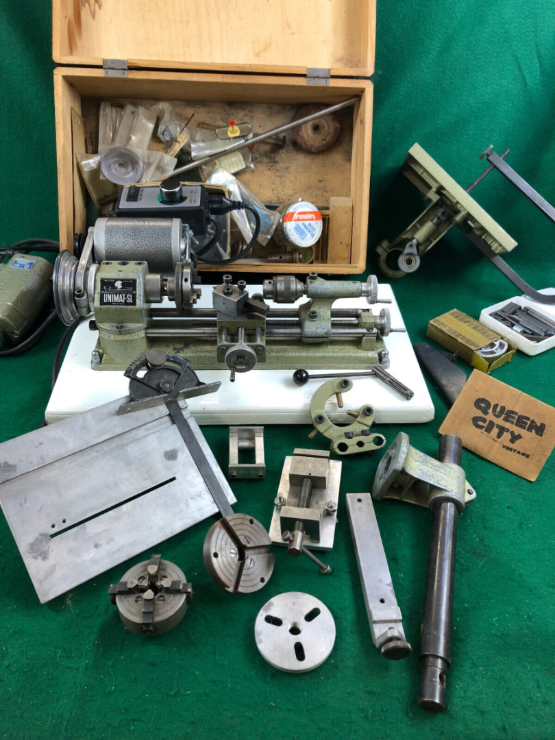
Yes, what you have there is an Atlas, or an "Atlas/Craftsman" (Atlas badged by Sear, Roebuck, and Co.) 12"X42"16-speed Standard model machinist's lathe. That model was, as near as I can tell from the photo, the introduced in 1939 and continued in production throughout the War and up to the late '40's or early '50's. (You can look up the serial number online someplace and get the actual manufacture date.) There were reportedly a very large number of them manufactured during the War to be used for "piecework" war parts production by home shop machinists. There are still many around in the various configurations in which they were made. Early Craftsman Metalcraft & Metalmaster 9" and 12" Lathes and Atlas - 12-inch Lathe (Late Models including the Craftsman) Manual & Data Pack | store.lathes.co.uk at Lathes.co.uk . I have a Unimat DB modeling lathe, a 1950 Craftsman wood lathe, and one of the Craftsman/Atlas 12"X42" machinist's lathes (which I believe were also made in a 36" bed version.) The metal lathes are fine for turning wood. Tool rests which mount on the cross-slide of metal lathes for wood turning are common accessories for metal lathes. I use my metal lathes interchangeably for wood and metal work and they handle it just as well as my woodworking lathe. The woodworking lathe does have the advantages of being less complicated, handling larger work pieces for the price, and being a lot less expensive to buy over the machinist's lathes, but it won't turn metal and it isn't capable of the high accuracy tolerances the machinist's lathes are. The one drawback with using a machinist's lathe for wood turning, is that unless care is taken to cover the lathe machinery as well as possible when turning wood, the huge amount of sawdust and shavings created by turning wood will end up clogging everything on the oil-covered machinery of the machinist's lathes and require serious cleaning and re-lubrication on a regular basis if they are used primarily for turning wood. I find liberal amounts of tinfoil and masking tape greatly minimizes the problem. The little Unimat is good for turning small parts, drilling, and milling. It's easily moved around and can be operated sitting down at a table. It was given to me for nothing, and I rebuilt it, but just about had to take out a second mortgage to pay for the parts and proprietary tooling necessary to do basic turning and milling work on it. There's an active second-hand parts and accessories market for all things Unimat, primarily on eBay, since they've developed a cult following, but the various attachments and accessories for which the Unimats are so famous are now high-priced collectables. The Unimat SL1000/DB200 (same machine, different model numbers) and Unimat 3 are excellent little machines, but only capable of relatively light weight work in softer metals, plastics, and wood. There are a multitude of YouTube videos and websites dedicated to the Unimat machines. For all their "charisma," I have to say without hesitation that anyone looking for a very small light duty lathe today would be far better off in terms of both price and parts and tooling availability buying a Sherline or Taig mini-lathe or, actually, one of the ubiquitous Chinese Sieg-manufactured "7"by" mini-lathes, making sure it came from one of the top of the line retailers such as Grizzly, who import those machines manufactured to the highest quality control standards. (This is why there is such a large difference between what Grizzly or MicroMark charge for the "7 bys" and what Harbor Freight sells them for.) The "7bys" are very common, their numbers support a huge after-market tooling selection as well as keeping prices low, they are sufficiently powerful to handle machining iron and steel easily, and they have the greatest weight by far of all the small lathes. The single most determinative factor in any machine tool's accuracy is its mass or weight. It's certainly a matter of opinion, but I think it's better to opt for the largest and most powerful lathe one can afford because, as mentioned above already, how much you can do with a lathe is only limited by its weight, working capacity, and power. Within reason, a large lathe can make small stuff, but a small lathe can't make big stuff. As has been said about other tools, when it comes to lathes "size matters." (See: Emco Unimat lathes) BELOW: Very nice Unimat DB200 with basic turning, drilling, and milling tooling, upgraded variable speed continuous duty motor, and table saw and scroll saw accessories at a very reasonable price. A decent basic lathe without tooling and the original intermittent duty motor will run around US $750.00. Vintage Unimat SL miniature/jewelers lathe DB 200 w/case, attachments Austria | eBay Several years ago, I was very fortunate to be able to obtain an Atlas/Craftsman 12"X42" lathe very similar to the one pictured in the post above, in very good shape, along with a huge number of attachments and tooling, from a retired master machinist's widow. It had been her husband's personal home machine, and he'd pampered it since it was new in the early 'fifties. It does not have the "quick change gearbox" attachment evident on some later models, so in order to cut any thread known to man or beast requires manually configuring the gear ratios, but that's a minor consideration unless you plan to do a lot of specialty threading of obscure thread types and sizes. It does have an aftermarket reverse rotation switch which is very handy for threading, but which can be a mixed blessing, since an inadvertent change in the rotation direction can cause a 20 pound-plus chuck to unscrew itself from the headstock spindle at speed! These Atlas/Craftsman lathes are highly desirable for home hobby use and there is a fair amount of aftermarket parts and accessory manufacturing ongoing even though the machines are long out of production. As happens with popular models of old machine tools these days, when one wears out, it inevitably is cannibalized by the used parts cottage industry and ends up for sale in bits and pieces on eBay, so you can pretty much find any part you need there. (See: Craftsman Atlas 12" lathe for sale | eBay) As with so much "old 'arn," these Atlas/Craftsman lathes are "oldies but goodies." Mind you, they are somewhat light weight for their capacity, but that's a relative concept and they aren't slouches in the power department. They get some criticism for their flat ways vis-a-vis rigidity, but I've never had any problems with that. If I had the option of a South Bend in the same size category with all the tooling I've got for the Atlas/Craftsman, sure, I'd take the South Bend which was the "Cadillac" to Atlas' "Chevy," but there are a lot more Atlas/Craftsman lathes out there and they're still "takin' a lickin' and keepin' on tickin'." My lathe certainly can do a whole lot more than I'll ever figure out how to do on it, so I'm not complaining. The internet is full of information on the Atlas/Craftsman 12" lathes. All of the original manufacturer's literature is still available, such as maintenance and operation instruction manuals as well as a ton of after-market publications. YouTube is full of videos on the subject. The well-known YouTube retired shop teacher and machining instructor "Tubal Cain" AKA "Mrpete222" has many very helpful videos on these lathes specifically, as well as on machinist work generally and is a very valuable resource. (See (12) Mr. Pete 222 + atlas lathes - YouTube) Hell yes! Your Atlas/Craftsman 12"X42" lathe is worth restoring! It's a real gem that a lot of guys would give their back teeth for. From your description, I'd say it probably needs routine maintenance rather than "restoration." The threading dial gears apparently wear out and are regularly available on eBay. (See: Atlas Craftsman 10" 12" Lathe Thread Dial Indicator 9-63 | eBay ) You should check out your spindle bearings if you have play in the spindle. There are two types of spindle bearings on the Atlas 12's, old school poured babbit bearings and modern Timkin roller bearings. If your babbit spindle bearings are worn (which I've read does occur, but I'm no expert on the subject) you'll have to pour new babbit bearings and that's something I'd find some old school machinist to show you how to do, or perhaps, if possible, you can retrofit your lathe to use the Timkin roller bearings, which are readily available generic parts. It is indeed unfortunate that you didn't have your father-in-law work it over for you before he passed away. I think most of us have one of those sorts of stories in our past! I hope you have a lot of tooling with your lathe. If not, fortunately unlike the Unimats and a lot of other lathes, there's plenty of Atlas/Craftsman 12" tooling around as well as lots of generic tooling that will fit it perfectly since it's all standard U.S. threading and Imperial measurements. The cost of tooling is always a big consideration in choosing a lathe. The rule of thumb is that basic tooling alone will run about as much as the cost of the basic lathe when new. If you have a lathe that can use the inexpensive tooling that's imported from China and India and you don't need the close tolerances of the super-expensive highly accurate U.S. and European tooling, you can save a bundle. There are a few specialty attachments you may want to acquire for your Atlas/Craftsman 12" when you have some "mad money." I would consider a decent collet holder and collet set and the proprietary Atlas 12" milling attachment that permits using your lathe as a milling machine as near "must haves," with the Atlas 12" tapering attachment bringing up a close second. Your Atlas 12" is a "medium" sized lathe that will allow you to do anything you would want to do on any of the smaller lathes while at the same time permit you to do anything larger up to what would fit into its theoretical "capacity envelope" of a 12" by 42" cylinder shape. It's definitely a "keeper" unless for some as yet undiagnosed reason it has some fatal defect that renders it unusable and is too expensive to make repair worthwhile. Should that occur, you probably will have little problem "parting it out" and making enough selling the parts on eBay to buy a new Sherline!
-
Funny coincidence. I happened to see this book listed in the WoodenBoat Store book section: Crash Boat published in 2021. It apparently recounts the exploits of the ASR's in the South Pacific. I thought it might be of interest to you if you haven't come across it in your research as yet. See: Crash Boat: Rescue and Peril in the Pacific During World War II: Jepson, George D.: 9781493059232: Amazon.com: Books (Shop around, it may be available for less elsewhere. Apparently available in both hardcover and paperback.)
-
Excellent advice about powered modeling tools! To this in fourth place after the above mentioned three, I'd add a quality stationary disk sander and I'd say move heaven and earth to buy one of the new Byrnes 4" variable speed disk sanders. There are lots of cheaper alternatives on the market, but the mass of the disk and the variable speed set the Byrnes variable speed model light years ahead of the rest. If that's just too costly, you should at least get the regular Byrnes 5" fixed speed disk sanders. Nobody I know of makes a better fence and table system on a disk sander than Byrnes.
-
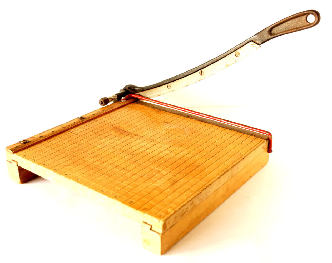
Easier still is a method I've used with satisfaction: Laminate "Hahn style" frame shapes (and whatever else desired) with PVA glue using birch tongue depressors sold in quantity dirt cheap at craft supply stores. These can be neatly "chopped" at angles using a standard "classroom" paper cutter, which, BTW, is also a very handy ship modeling tool.

-
Before anybody buys an airbrushing rig, I strongly suggest they read the thread linked below. Pay particular attention to Kurt Van Dahm's comments at post #7. Kurt is MSW's airbrushing expert, as far as I'm concerned. (And it appears the Badger airbrush company shares my opinion!) I expect if you send Kurt a PM, he will be able to recommend something that best meets your needs at your chosen price-point. Note also that I believe the MSW sponsor, USA AIRBRUSH SUPPLY, offers discounts to MSW members. Your 85' ASR build looks like it's coming along very well. I have a bit of first-hand familiarity with this family of "crash boat" vessels. There were several around San Francisco Bay "back when" and at least one of the 85 footers is still afloat and operational on the S.F. Bay and Delta waters. See: Testimonials (homesteadcloud.com) They were quite popular with the Sea Scouts, who apparently were at one time able to get them for nothing as government surplus. A friend of mine's father skippered the Air Force ASR stationed at Hamilton AFB in Novato, CA on S.F. Bay as recently as the late 'sixties or early 'seventies. The widespread misconception that the hulls of the PT's, ASR's, and similar small craft built in WWII were built of plywood deserves to be dispelled. Plywood was used in the construction of flat surfaces in these boats, such as decks and bulkheads, but not in their curved hull surfaces because their hull forms contained compound curves (where curves go in more than one direction at a time in the same piece of material.) Because the plies of plywood are laid in different directions, plywood can only be bent in one direction and is not suitable for developing compound curved shapes. The wooden hulls of the WWII production small craft in question were built with multiple layers of traditionally spiled planking fastened together with glue and mechanical fasteners, the compound curved shapes being developed in the lay-up of the planking layers. This is a much more involved construction process than simply nailing sheets of prefabricated plywood to a frame. All of the 85 foot ASR's were double-planked with a layer of canvas laid in waterproof adhesive between the planking layers. The inner cedar planking was hung at 45 degrees to the diagonal, 1/2" thick below the chine and 7/16" thick above the chine. The Honduras mahogany outer planking was hung horizontally and was 3/4" thick below the chine and 9/16" thick above the chine. The inner planking was fastened to the longitudinal timbers with bronze screws and to the frames with copper nails. The outer planking was fastened through the inner planking into the frames with bronze screws. The inner planking was then fastened to the outer planking with bronze screws from the inside. The decks were 3/4" fir plywood, fastened with Monel ring-necked nails to the deck beams and with bronze screws to the shelf and clamp. The decks were canvas laid over white lead paste. The 85 footers were decidedly not planked with plywood because their hull shapes included compound curves which are not possible to develop. The planking was finished "fair" (smooth) as might be expected, so planking and filling your model hull with a sanding filler and then painting will permit you to use wider planking stock as you have used on the bottom, but I would expect that the graceful curves of the bows will be more easily developed with narrower planks than you were able to use below the chine. If you haven't come across it already, you will find the "U.S. Crash Boats" website a goldmine of information on the entire "crash boat" and "Air-Sea Rescue" class with specific information on the 85' ASR's. This site provides more information than I've ever seen on this type of site. It has PDF's of all the applicable manuals, design and construction details, and even extensive crew lists for all of the crash boats. See: 85 ft. Army Air Force Rescue Boat (uscrashboats.org) See also for a large number of interior and exterior detail photos highly useful for scratch modeling: Boats: Crash Boat, Aviation | Flickr .
-
Growing up, we lived in a house with hardwood floors that required regular waxing with one of those "iron holystones," too. When I got old enough, that job fell to me. I was greatly relieved when Bissell came out with an electric floor waxer for home use! I have no idea whatever happened to that old hand buffer that I had to swing back and forth. It'd be good for a "What is this tool?" contest these days.


