
HOLIDAY DONATION DRIVE - SUPPORT MSW - DO YOUR PART TO KEEP THIS GREAT FORUM GOING! (89 donations so far out of 49,000 members - C'mon guys!)
×


Pirate adam
-
Posts
242 -
Joined
-
Last visited
Content Type
Profiles
Forums
Gallery
Events
Everything posted by Pirate adam
-
I love the colors of the wood. It is a really cool look. Adam
-
I’m not sure I would buy an airbrush just for wood ship modeling, but they are certainly a wonderful tool, especially for painting on metal and plastic. My go to is an Iwata from Hobby Lobby combined with a regular garage air compressor equipped with a proper pressure regulator and moisture trap. I concur with Kurt that it is worth using the thinner recommended by the manufacturer despite the myriad other options people recommend. I agree with Kurt that they provide opportunities for effects that are very difficult to replicate any other way. There is a bit of a learning curve, but lots of videos on YouTube, etc. Adam
-
Kevin, I love every time you say “I just need to build the skill.” It is a great reminder that one of the cool things about this hobby is it involves mastery of so many different skills and almost all of them are pretty manageable with enough practice. Adam
-
Siggi, It looks amazing. I’m glad you were able to get it the way you want it. There is no point having a little detail that will make you dissatisfied whenever you look at the model. I love the colors. Adam
-
Nate's PANDORA in 3D
Pirate adam replied to 3DShipWright's topic in CAD and 3D Modelling/Drafting Plans with Software
Nate, The first thing that I came across was the number of transoms. The Anatomy of the Ship book shows 5 transoms. My shear plan of Crocodile shows 4 transoms. All of the other Porcupine class ship drawings I have seen also show 4 transoms. This is consistent with my interpretation of the tables in Shipbuilders Repository. The other point was the big difference between the various disposition of frames drawings I could find for ships in the class. The disposition of frames drawings for the Porcupine class do clearly show the diminishing timbers. I made the assumption based on the disposition of frame drawings that the frame bends had air spaces separated by chocks vs the Anatomy of the Ship book which shows the bends as adjoining frames. I will add this is a very interesting discussion. I don't have much to add in terms of debate. I am surely not an expert in naval architecture. It is clear we both started with a different set of assumptions going in which results in a different result in the end. As I said in my original post the fact is no one knows for sure. The most important thing is your 3d model is awesome, and I really enjoy every post. Adam -
Nate's PANDORA in 3D
Pirate adam replied to 3DShipWright's topic in CAD and 3D Modelling/Drafting Plans with Software
Nate, This is a topic I spent a lot of time agonizing over for my Crocodile build. I was planning to use the framing pattern straight out of the Pandora book but quickly found some discrepancies with the shear plan I have of Crocodile from the National Maritime Museum. Added to that the framing plan in the Pandora book just doesn’t make a whole lot of sense from an engineering perspective. Parts of the ship seem hopelessly compromised in terms of strength for no apparent reason. The NMM has partial framing plans for several of the other Porcupine class ships. Some show a number of cast frames and some use shifted frames. None look anything like the framing in the Pandora book. Interesting the NMM doesn’t seem to have any drawings of the actual Pandora. I would recommend looking up some of those plans for guidance or as a pretty good approximation the framing diagram available for HMS Sphinx. It is a very similar size and shape of ship. On the other hand your 3D model is already pretty awesome. It all comes down to whether you are striving for historical accuracy or creating a cool model of what is in the book. The fact is no one alive really knows what the framing looked like and it may have changed some in the major retrofit of the ship. Adam -
Alan, There is loads of info on painting really tiny figures online especially from the wargaming guys. I am not especially good at it, but I have found some of the videos super helpful for painting pilots for plastic airplanes. Some of their tips aren’t always especially obvious to me especially when it comes to order of painting colors etc. I’m sure you will end up with a cool 1/64th version of yourself. Adam
-
This is exactly how I felt as an American posting a Spitfire build on the Britmodeller site, lol! I’m sure you would do an amazing Constitution, but do agree it has already kind of been done to death. Adam
-
Kenny yours really looks like it has spent a lot more time in the weight room than the kit version 😀
-
USS Constitution by mtbediz - 1:76
Pirate adam replied to mtbediz's topic in - Build logs for subjects built 1751 - 1800
The ship is really starting to come to life with the addition of the smaller details. Beautiful build. It really makes me want to try to visit the real ship in Boston. Adam -
Looking very sharp. Adam
-
It will be fine in the end, but if you managed to do that without absolutely pealing the paint with a profanity laced tirade you are a better man than me 🙂. I’m glad the hull wasn’t damaged at least.
- 257 replies
-
- 1
-

-
- pegasus
- Swan-class
- (and 1 more)
-
Walmart.com has telescoping square mailing tubes as singles or packs of 6 Adam
-
Chuck, I actually looked into AI for STl files after reading one of your other posts a few days ago. It seems there is almost no end to what is possible with really sharp pictures from the historic (or modern) models. Another thing that is becoming commonly available is handheld 3D scanners. Even huge things are now being scanned with LIDAR scanners. Of course this requires more access than most of us will ever have but I can see the museums being open to scanning things over time for archival purposes. I used to have second thoughts about the role of 3D printing stuff like carvings and small parts, but I have really come around to the benefit of allowing those of us that are pretty crafty but not necessarily artistic to take on models of almost any subject. I think it is an amazing enabler for the hobby. I love what you are doing. Adam
-
Johann, I continue to be amazed by the detail of your research combined with the level of craftsmanship on your model. It is inspiring how much work you have put into answering questions related to details most people would just skip over. I hope you realize your build log is surely becoming one of the most valuable resources related to rigging in this period available on the internet. Thank you very much for sharing. Adam
-
Chuck, This is a cool idea for hopefully making the hobby a lot more accessible for people just getting started or who don’t have the tools to scratch build a lot of the tiny bits. It is amazing seeing the possibilities being unlocked by laser cutting, computer aided machining, and 3D printing. I am blown away by the quality of the latest things I am seeing with 3D printed carvings, figures, and bits like your capstan base that would normally take a ton of work in metal. Adam
-
Thank you Druxey. I think I will do that for the other side. I was weirdly nervous about making the holes too big, but making them in advance will save some risk later. I bought some sanding cord that I will use to make the existing holes bigger to where I get my little needle files in. Adam
-
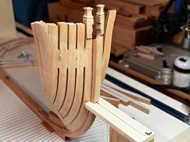
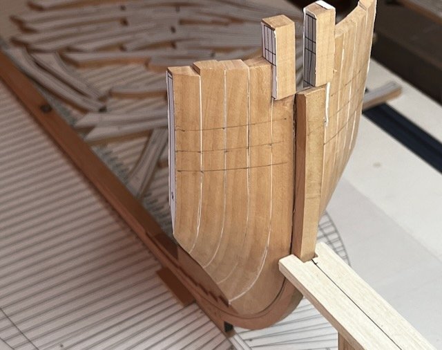
I finally got a chance to start assembling the bow section. One side complete. This was very satisfying after wrestling with the hawse timbers for weeks. I will be very happy when this part is done and I can move on to the remaining cant frames and finally the square frames.
-
The blocks look really good. I like the color. They look like ancient wood. They also look fun as an army of blue droids.
-
Looking good. I love the shape of the French frames with the extreme tumblehome. Adam
-
Looking amazing. The milling is tricky and you made it look easy. Adam
-
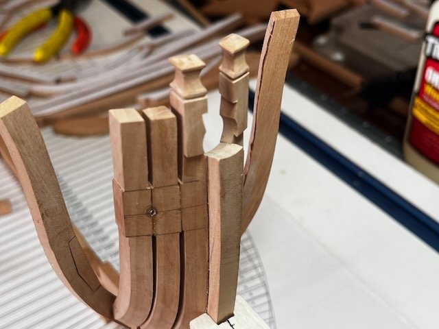
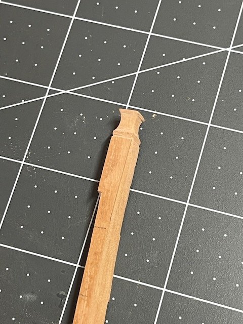
I formed the knight heads on the top of the bollard timbers. I just used chisels, files, etc. The shape on my admiralty draught was relatively easy to form. Next step will be to file in the opening for the bowsprit and its chock. I hope not to encounter another piece on the ship as complicated as the bollards. Adam

-
I then removed the frames from the model and pulled them apart. This was super easy due to label paper on the frames. I then cut down each frame using the mill to create the air gaps. I won't even get into how many hawse timbers I made to get to this point before everything looked right and fits properly with the first cant frame. Next I will file in the hawse holes per the instructions in the Swan practicum. I also still need to do a bit of shaping of the bollards to get them to fit properly on the tapered stem, and then I will try to shape the knight heads. Adam
-
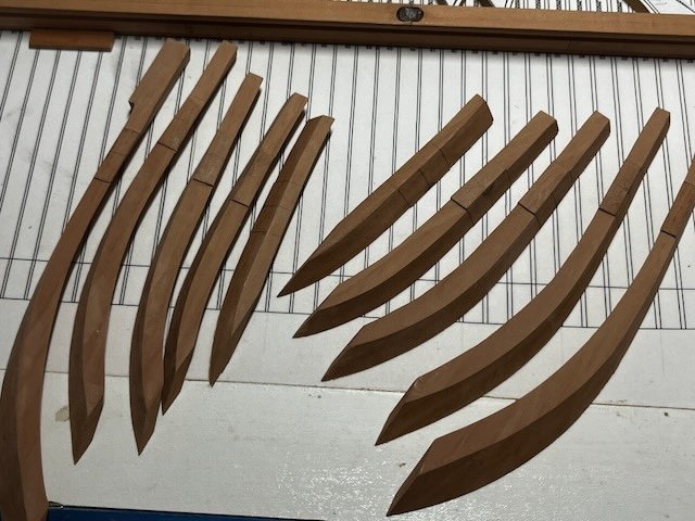
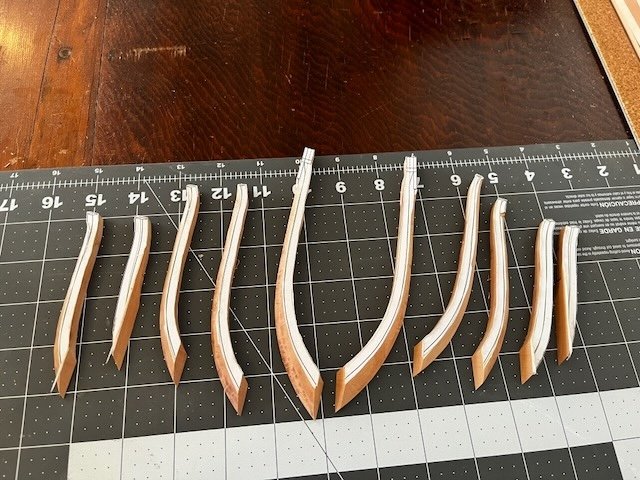
Finally some progress on the pointy end. I cut out the frames in the usual manner. I printed out an extra set of frame drawing, so I could add them to both sides of the frames. I did some pre-beveling, and then glued all the frames together into 2 stacks (not shown). I then did some shaping on the inside and outside of the frames before temporarily attaching to the stem. I marked the heights for the hawse holes and the level of the material that will remain when I cut the air gaps.
-
Pear, boxwood, and holly would all work great depending on the look you are going for. I would recommend looking through the various build logs and seeing if there is a certain look you like more than others. I would probably go with wipe on poly vs tung for some of the lighter woods, as it can give a bit of an orangish hue over time that probably isn’t what you are going for. I definitely love the look of tung oil on pear or cherry. Adam


