
HOLIDAY DONATION DRIVE - SUPPORT MSW - DO YOUR PART TO KEEP THIS GREAT FORUM GOING! (Only 69 donations so far out of 49,000 members - Can we at least get 100? C'mon guys!)
×


Pirate adam
-
Posts
241 -
Joined
-
Last visited
Content Type
Profiles
Forums
Gallery
Events
Everything posted by Pirate adam
-
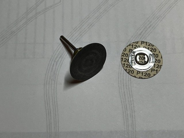
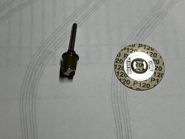
This is the attachment I like. It attaches with a spring loaded clip on the shaft so no hole or fitting on the front of the sanding disk. They use the same attachment for some of the polishing wheels .
-
Alan, It looks great. I hope you chose enjoy summer! Adam
-
I just went through this process on my Crocodile build and will start with the bow cants soon. I used just about every tool imaginable. I will ask Druxey to close his ears when I say I did a ton of the fairing with a sanding disc tool (one that attaches perpendicular to the shaft via a clip on the back - not the drum shaped sander which guarantees disaster) on a Dremel tool equipped with a right angle attachment. Using a 120 grit disk at low speed allows to remove material at a reasonable pace without too much risk of disaster. Keep in mind I left a full 2mm inside the lines of the frames so plenty of wood to work with. You do have to be careful so not to ruin frames. Then I switch to hand sanding with sandpaper glued to various pieces of plywood, thin battens, etc. it is something best done a little at a time over the course of days. I will still need to do some thinning of the frames later which I I’ll do entirely with hand sanding. It is a bit shocking to see how thin the frames are when you get to the prototype thickness which is 5.5” at the heads for my model. The tiny size of the timber heads is one of the first things that jumped out seeing some of the dockyard models in person at the navy academy museum. Adam
-
Dale, Below are a couple pictures of rope displays I have been lucky enough to come across. The first is from the ropery at Chatham dockyard. The second is from Mystic Seaport. They show that even in new rope there is a pretty wide variety of colors that would change over time. The ropes in the Chatham display are from left to right hemp, Manilla, coir, sisal, and synthetic. The ropes from Mystic are labelled. Some of the hemp ropes from Mystic are tarred as well. If you are interested in rope making I would recommend doing a google search for the ropery at Chatham Historic Dockyard. It is super interesting and there are lots of pictures of the process. They continue to make and sell rope in the same facility used to make ropes for the Royal Navy in the age of sail. Adam
.jpeg.470fc2171e3cffc4e1531eb9ac733381.jpeg)

-
My main advice especially on this portion of the ship is to make sure to leave plenty of wood for fairing once the frames are in place. It isn’t all that much fun to remove later, but it is tons easier and will look nicer than if you need to add shims later. It is SO easy to accidentally take too much off when you cut the bevels off the model. Adam
-
There is a good planking diagram for a 74 if you search for Berwick 1775. I look at the Arrogant and Elizabeth drawings a lot, as I am looking at Edgar 1779 as a possible one-day "ultimate model". Adam
-
That is awesome. Adam
-
Alan, Of course starting something new is just another part of the learning process, especially for a project as ambitious as this. The good thing is the risk of destroying the work you have already done is low. I am really looking forward to following the progress on the wales. It will make an already epic model even better vs settling on straight planks. Then the rest of us will be asking you for help! Adam
-
Kevin, I agree with Paul. Thank you for doing the podcast. What I loved about the podcast and all of your videos is the level of honesty regarding mistakes and how often you have to re-do parts, etc. I think that is super important for both newcomers and not-so-newcomers to the hobby to hear. I also loved your matter of fact comment that while you don’t currently have the right skill level to work with brass, you will of course have that in time. I think sometimes people forget that guys like David took a long time to master the various crafts in this hobby no matter how skilled they are. Looking forward to seeing Ulysses and of course the rest of Thorn. Adam
-
Siggi that turned out incredible! Very unique and beautiful. Adam
-
I think the red is the way to go. It looks good and seems more logical. Adam
-
I have had success in a similar situation using the cans of compressed gas used to clean computer keyboards. Stubborn bits can be brushed off with a soft paintbrush. Adam
-
Very cool model and nicely done. Adam
-
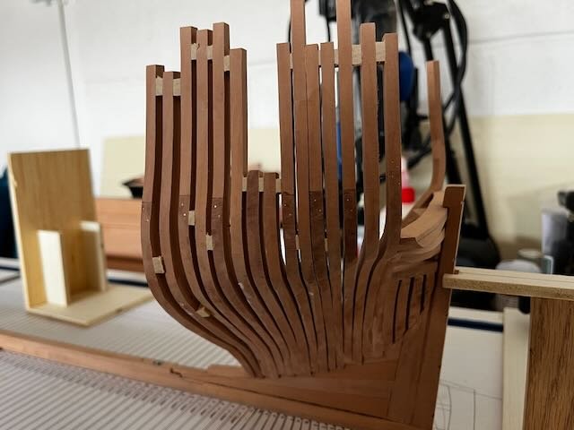
Stern cant frames all installed. Working on some progressive fairing and then on to the bow.

-
If it were me, I would go with what is shown in the planking expansion for HMS Sphynx. I have been working on the drawings for my HMS Crocodile, and I am constantly going back and forth between what is shown in the Pandora book and other sources. I think the Pandora book is a fantastic reference, but there are a few things that make me pretty skeptical about some of the drawings. The main thing is the authors make heavy use of inputs from a large variety of plans and models of ships other than Pandora or even ships drawn to the same lines. In some cases from much larger ships. It is a reality that this is necessary for some of the types for which less drawings are available, so don’t take that as a criticism of the authors or the quality of the drawings. There are sadly things that have been lost to history, but we are lucky a lot of great drawings are available for the Sphynx which is one of the closest siblings to your ship. Adam
-
Port side aft cant frames complete. On to the other side. Adam
-
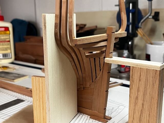
Slowly but surely moving ahead with stern cant frames. I'm doing a bit of progressive fairing as I go while trying not to go too crazy. I'm pretty happy with the look of the chocks. Just a tiny bit of contrast due to the grain direction, but still pretty subtle. Adam
-
I've started attaching the aft cant frames. No more until I add some basswood spacers at the top of the frames. Soon I will also start fairing the internal part of the stern before too much more gets in the way. Adam
-
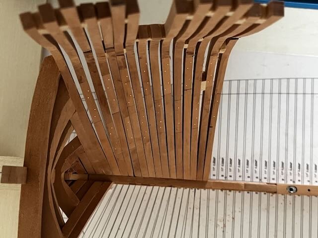
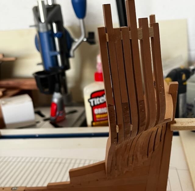
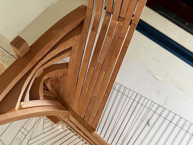
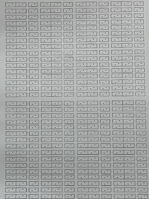
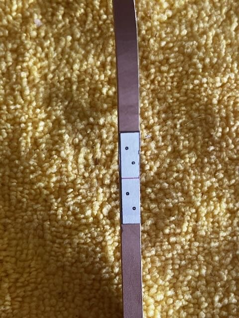
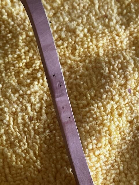
I finished gluing up the aft cant frames. My plan is to simulate the frame bolts with copper wire and blacken any exposed bolts on the model with liver of sulfur after fairing. I used wire labeled 0.019" diameter to simulate scale bolts 7/8" diameter. There are 2 types of joints on the cant frames. One type uses chocks and the other a simple scarph joint. I wanted to save some time laying out the bolt patterns on the frames, so I printed up some guides on label paper. I found that to work great. I drilled the holes using a micro drilling accessory on the Sherline lathe. I broke my last drill bit, so no more holes until I find some more. Adam
-
Yet Another Pandora 3D build
Pirate adam replied to herask's topic in CAD and 3D Modelling/Drafting Plans with Software
This is so much fun to watch. It really makes you feel like you are at the actual shipyard. Amazing work. Adam -
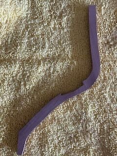
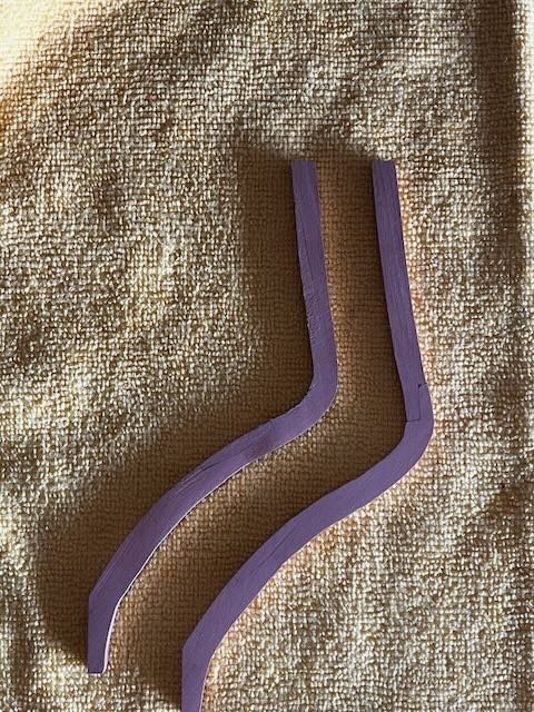
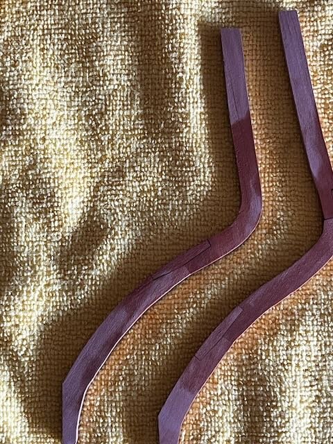
Cutting of frames for the chocks. I cut these using the Sherline mill. I simplified the chocks a bit by not beveling them. I only cut to the depth of what would be the shallower side so as to not expose the nose of the chock when the frames are faired. The chocks are a bit funny looking now due to the excess wood outside the actual frame lines. One side of the chock will be a bit off after fairing, but I don't think they will be especially visible when the frames are glued up anyway. I used regular scarph joints for the top timbers. I will pin them later with copper wire to simulate bolts. Here are two sample frames. With a bit of alcohol just to highlight the joints. I'm pretty happy with the look so far. There are 117 frames to do in total counting the hawse timbers, but the nice thing is they are a great project to work on just a bit a day after work. Adam
-
Wow that looks amazing Mark! Great work. Very impressive actually painting it on. Adam
-
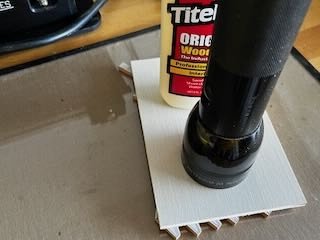
I forgot to show my high tech gluing setup. I glue them on a small plate of glass and weigh them down with a flashlight.
-
Picture with a bit more resolution.
.jpeg.002827fc6cb97213a0818b06bdfc6b4c.jpeg)


