


Glenn-UK
-
Posts
3,004 -
Joined
-
Last visited
Content Type
Profiles
Forums
Gallery
Events
Posts posted by Glenn-UK
-
-
-
-
-
-
-
-
58 minutes ago, Ryland Craze said:
Congratulations on finishing this beautiful model. I have enjoyed following your build log.
Many thanks. I am glad you've enjoyed the build log.
- mtaylor and Ryland Craze
-
 2
2
-
-
-
-
-
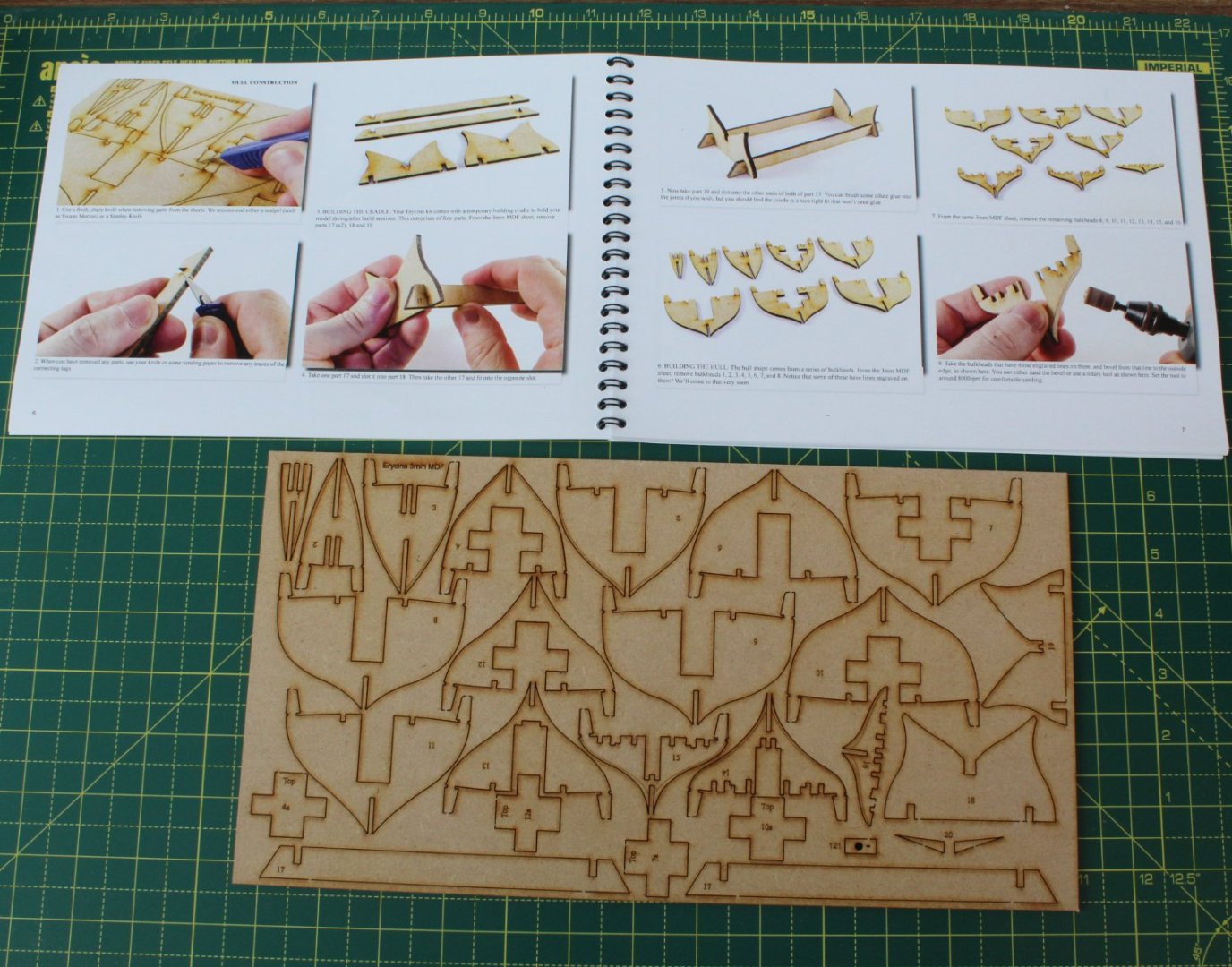
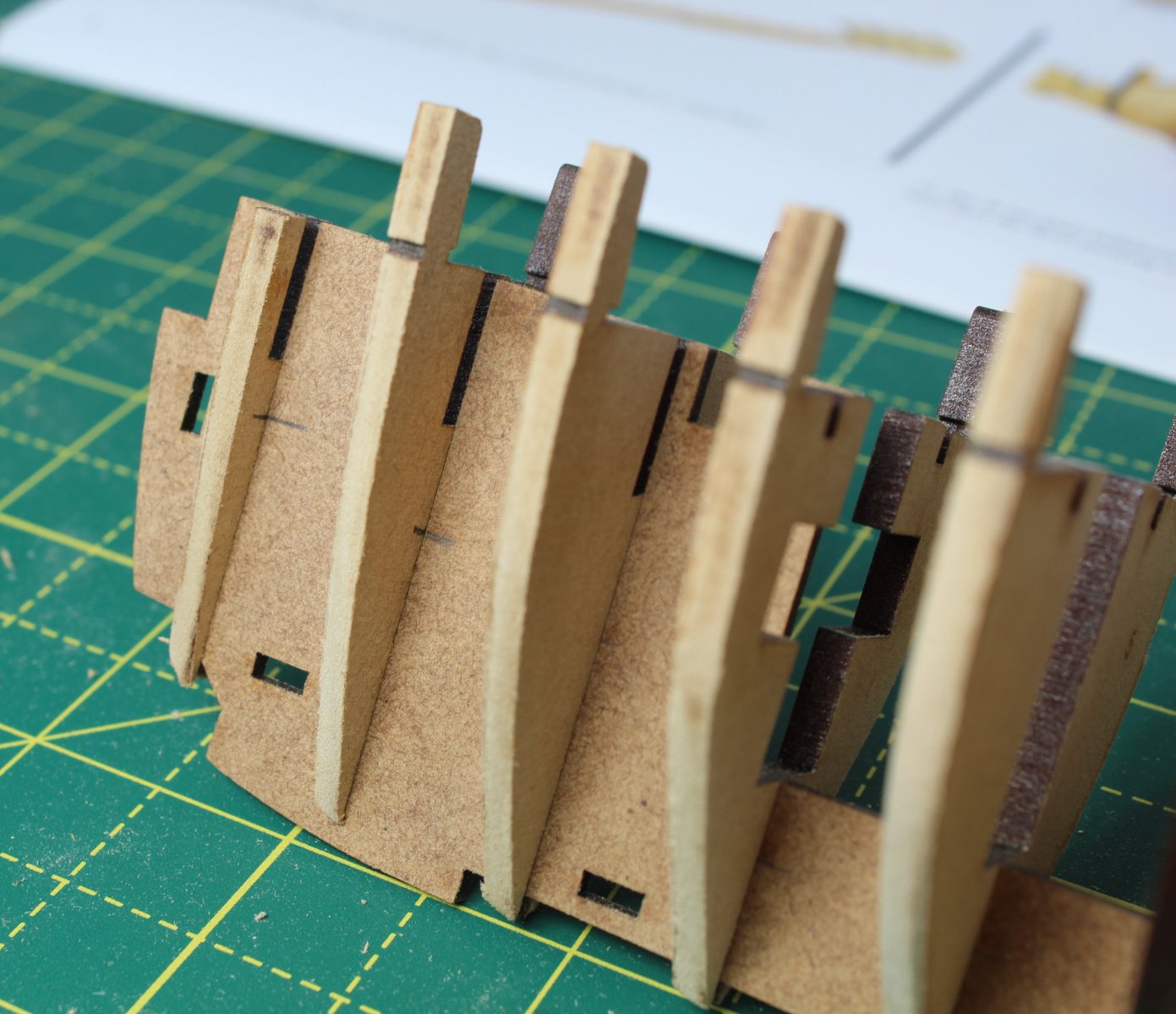
001 - Hull Construction Part 1
There is not going to be much of a description in this post as I have simply been following the build manual instructions verbatim.
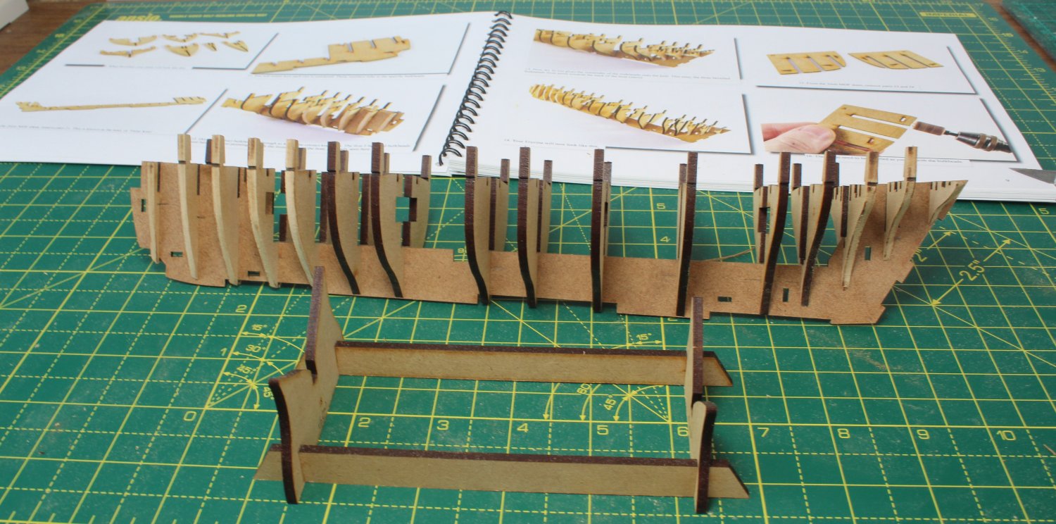
With the manual on the workbench along with the first MDF sheet I am now ready to make a start.
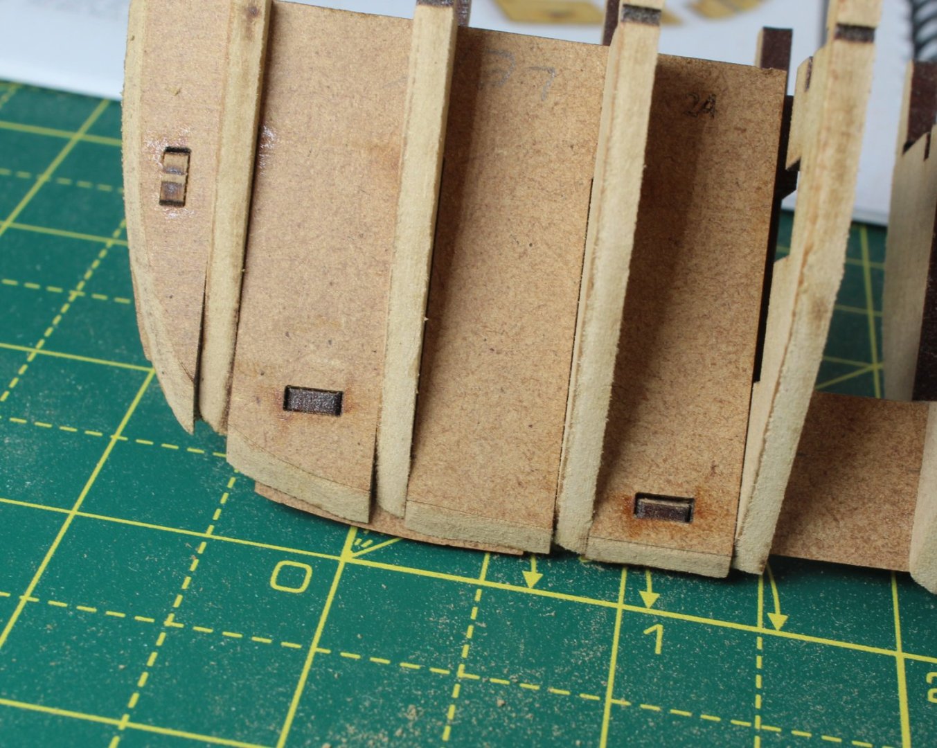
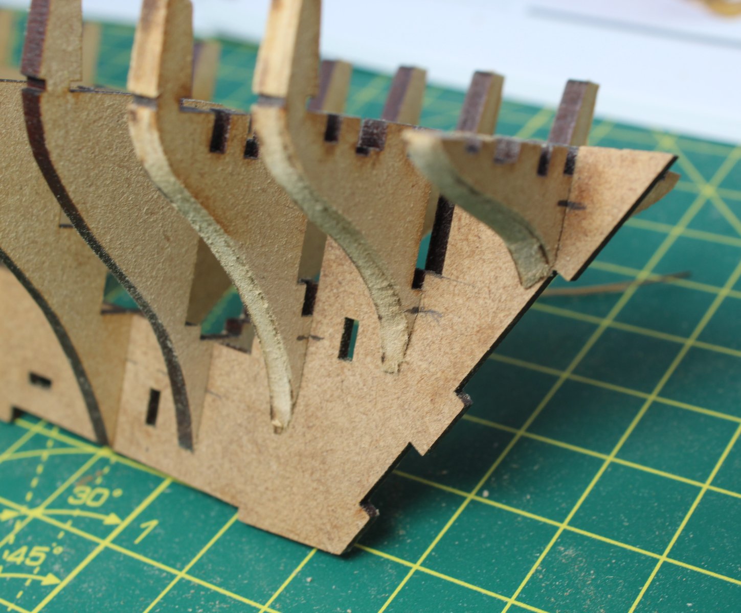
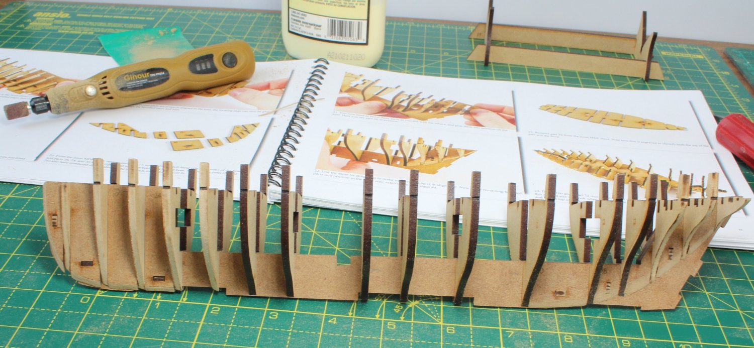
Using my rotary tool, the initial fairing of the first 5 bulkheads to the guideline was carried out. When I started on bulkhead 5, I had a senior moment started to apply a reverse camphor. I marked out the required sanding line on the other side of bulkhead 5 and carried on. Not a great start and I hope it is not a bad omen.

Next the camphor's were added the last three bulkheads. You will note, both on the previous photo and the photo below, that I have added some pencil marks on the bulkheads and keel. These marks indicate the bottom the locating slots. When the pencil marks are aligned, I know the parts are fully engaged.

Stage 1 completed

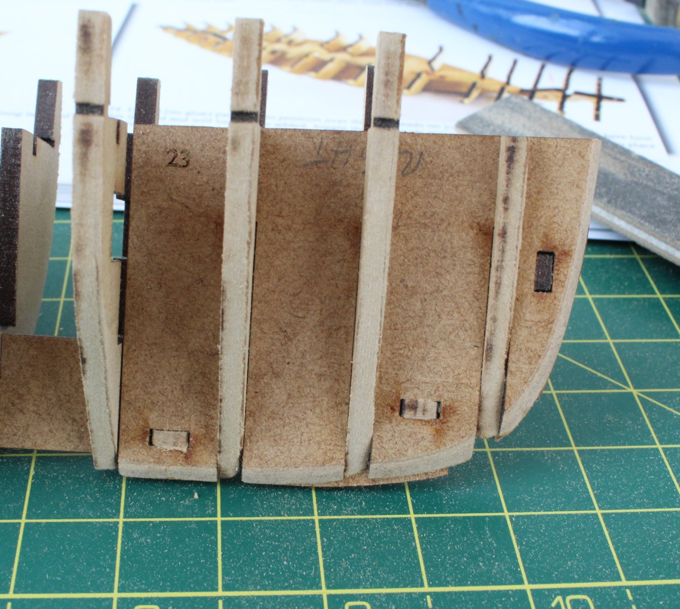
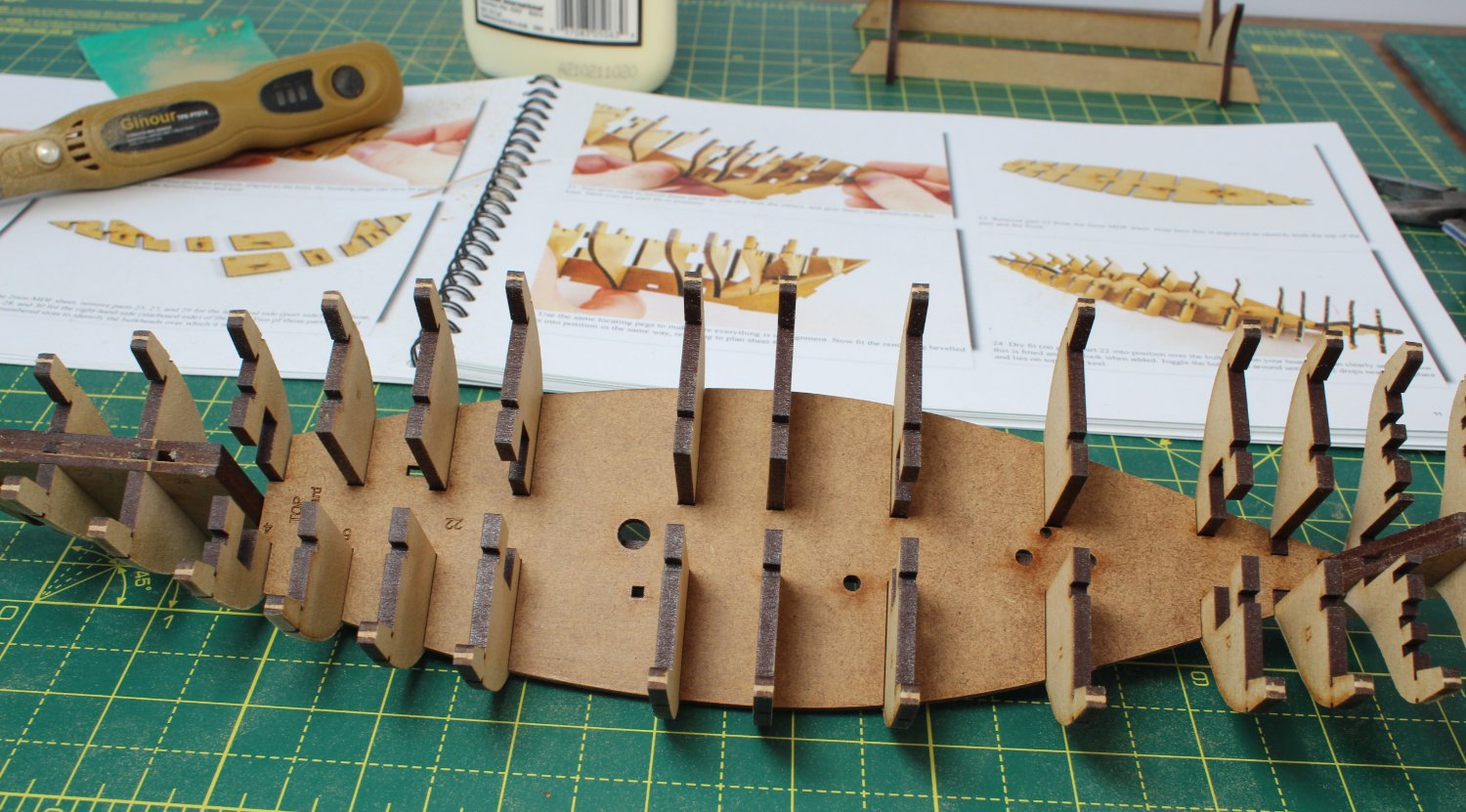
Next up was camphor and add the filler pieces. I need to review some other build logs to check the bow filler pieces camphor's along the keel edge with the bulkheads. There is plenty of material to sand in order to get a smooth line, or I can fill the gaps with some offcuts.


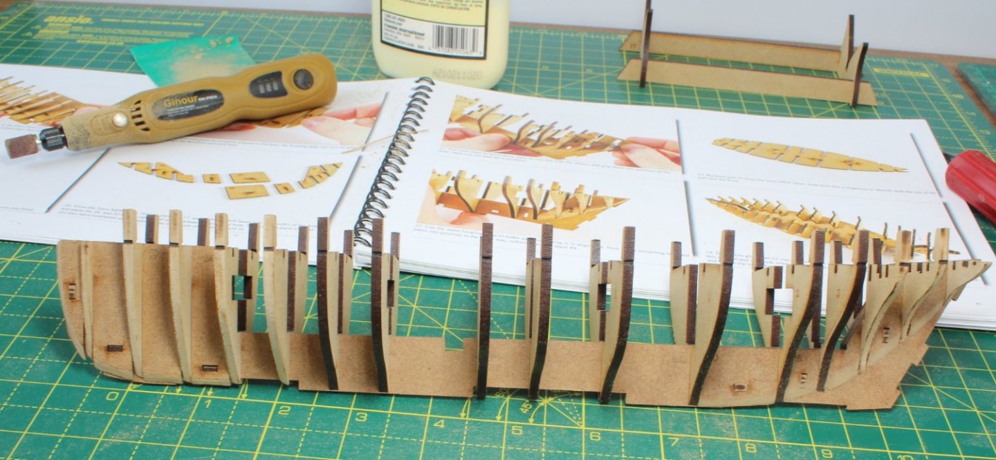
With all the bulkheads and filler pieces in place it was time to add the deck. Apart from the filler pieces, which were glued in place (as per the instructions), everything is still a dry fit.

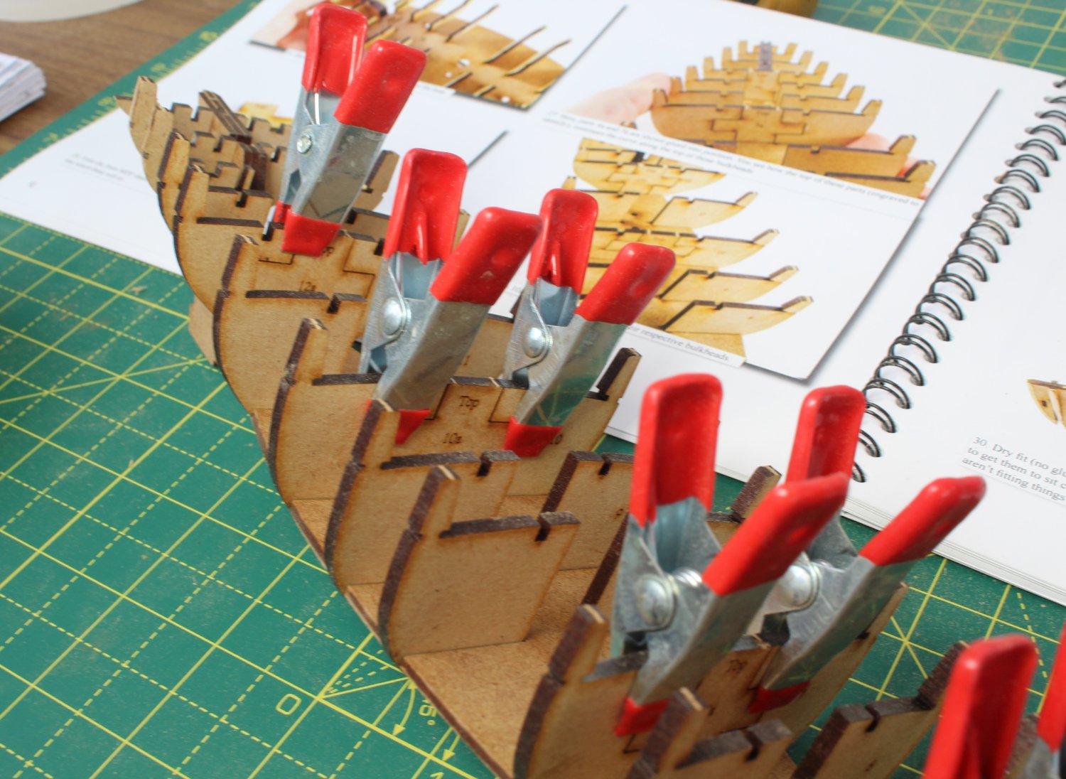
Bulkheads 12, 10, 7 and 4 require a cross piece to be glued in place. With the pieces in place, I used some clamps to hold the parts in place as the glue gripped.

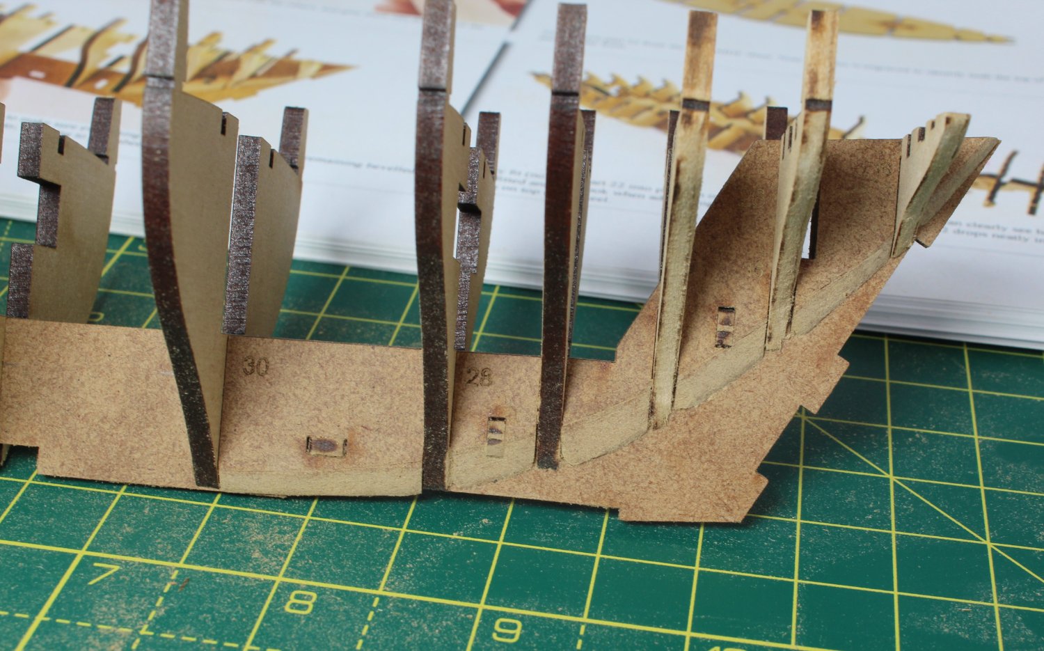
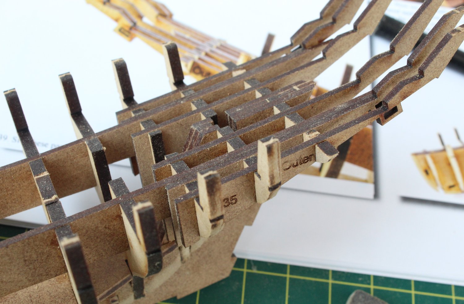
The two longitudinal hull brace patterns were slotted into place followed by the 2 sets of stern frames (inner, middle and outer).

With everything looking good I mixed up a diluted titebond solution and brushed it in between all the joints. The hull will now be left overnight to fully cure before I move on to the next build phase.
-
-
-
-
-
30 minutes ago, schooner said:
Absolutely stunning work! I'm bookmarking this log as a reference for all future sailing ship builds.
Congratulations and thanks for all the work in putting this build log together.
Glad you enjoyed the build log
- mtaylor and Ryland Craze
-
2
-
1 hour ago, James H said:
Doesn't it feel great to have finished something as complex as Sphinx!
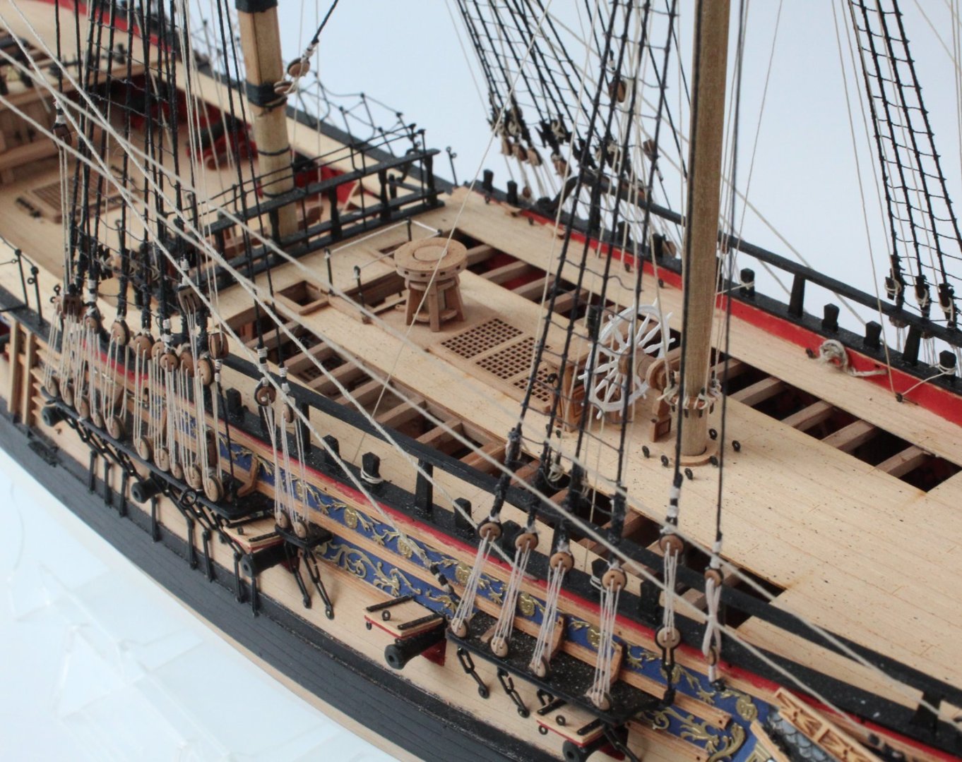
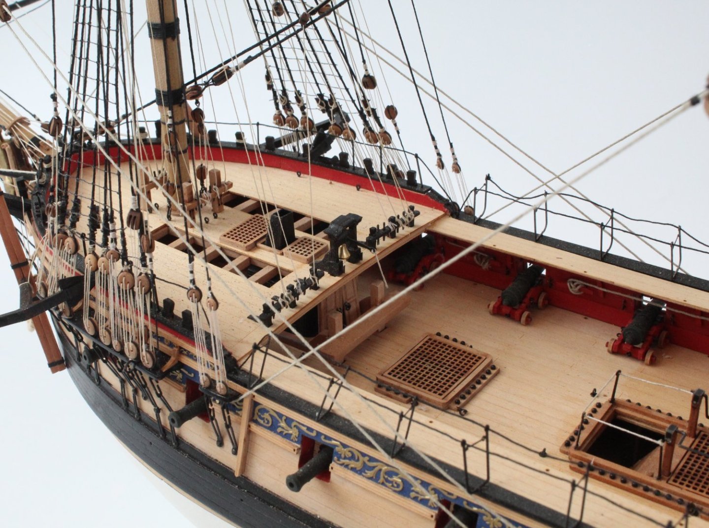
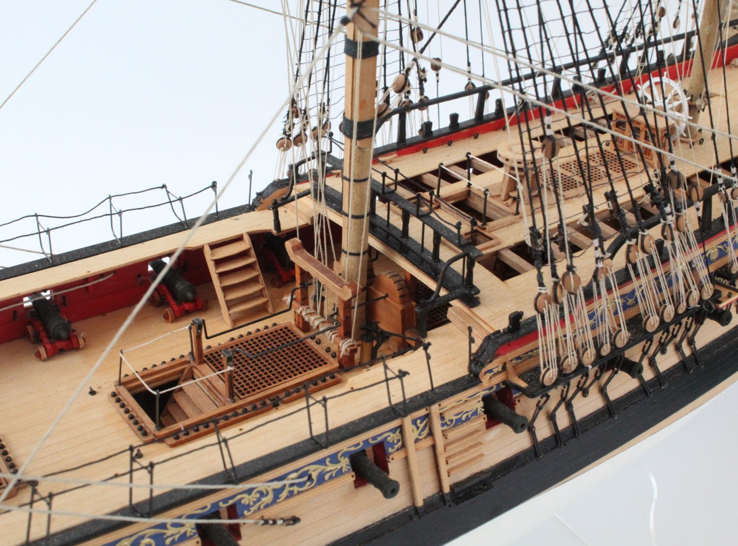
Well done, and it was definitely a nice move in starting over too. If I have one suggestion it would be to re-angle and tidy up the hammock cranes and rope along the gangways. ✌️
Many thanks James
It was a moment of great relief and happiness once I had added the two anchors yesterday afternoon.
I did manage to dislodge the seating (broke the glue seal) of the hammock cranes along the gangways during the rigging process which is why they are at a funny angle at the moment. I totally agree I should fix them back to the correct position again. I did keep pushing them back to the right position every now and then as I was rigging, but I did not reglue them to keep them secure as I knew I would keep knocking them with my big hands.
- hollowneck, mtaylor, James H and 1 other
-
4
-
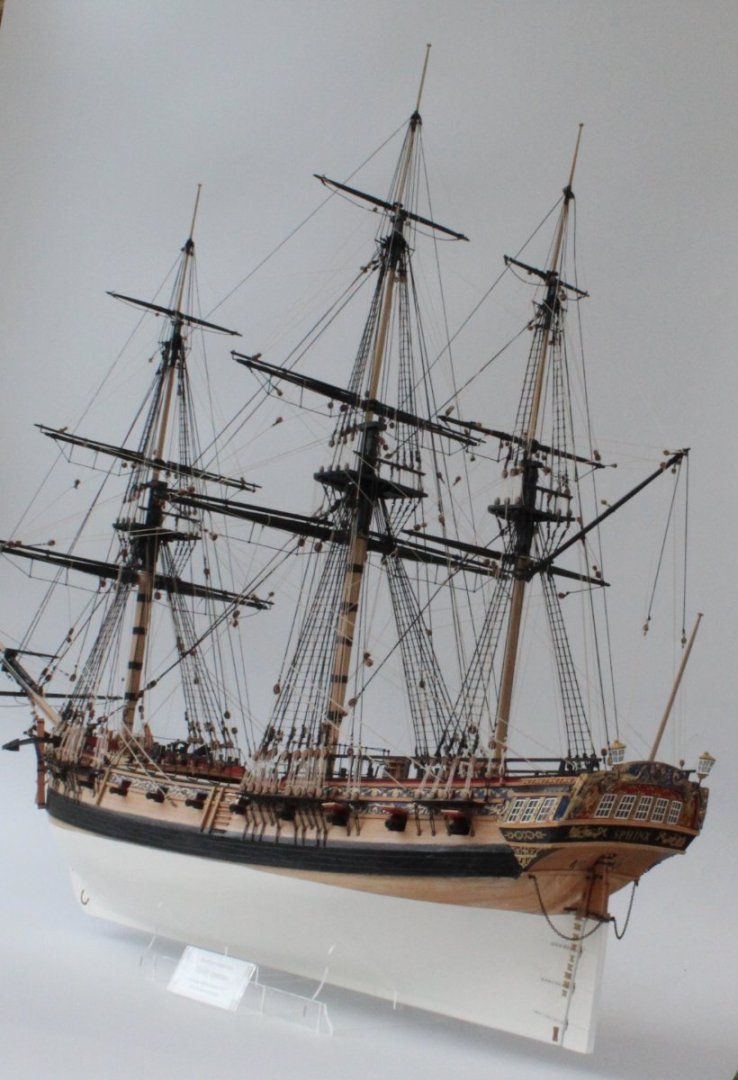
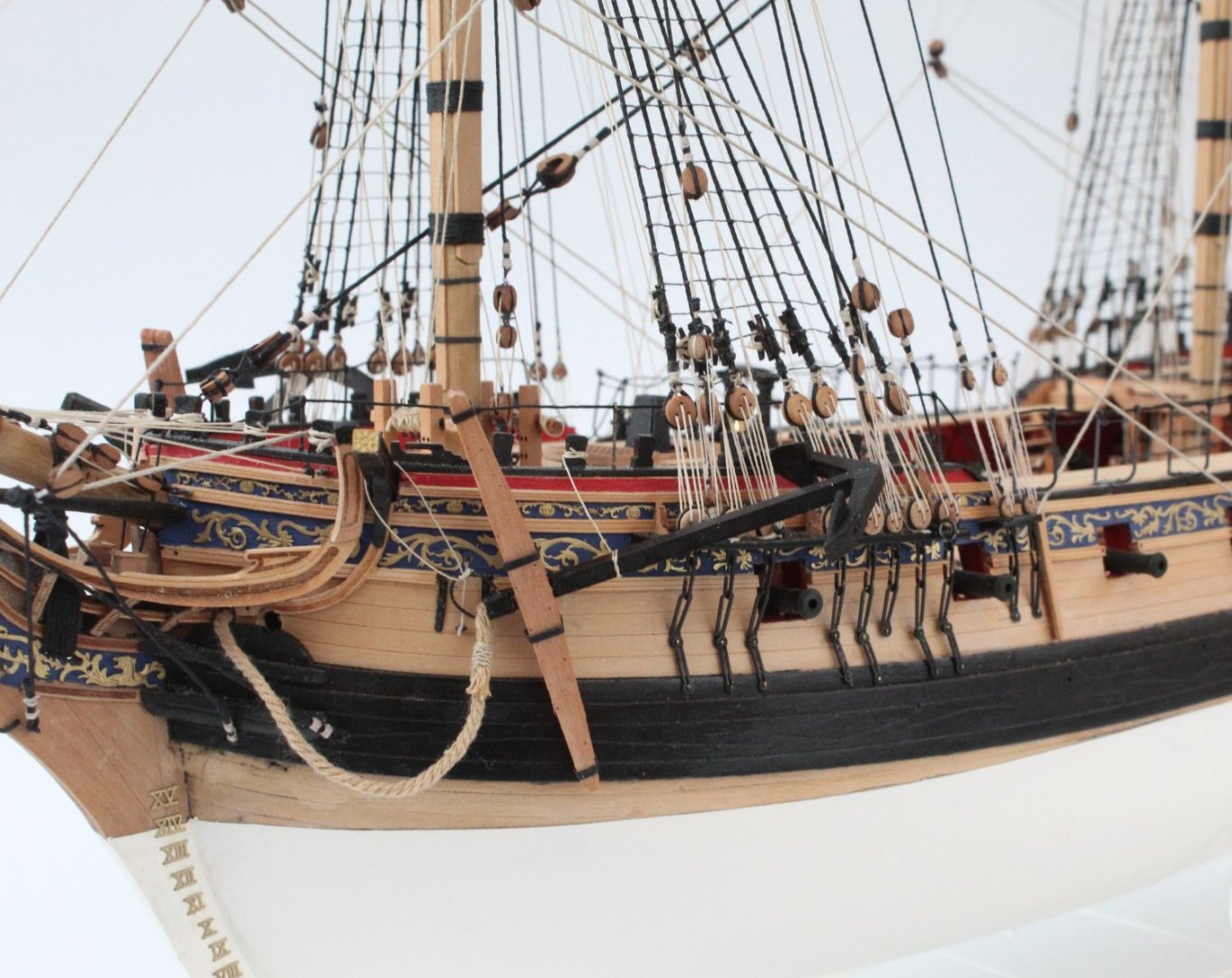
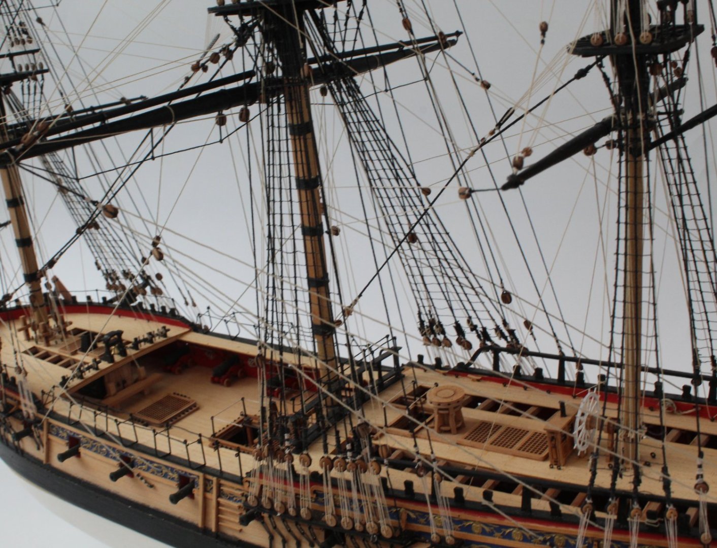
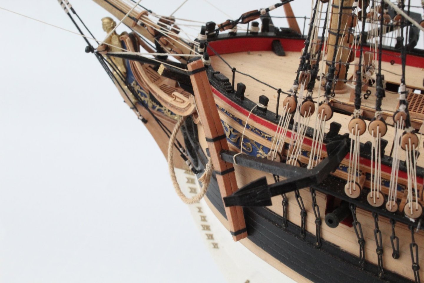
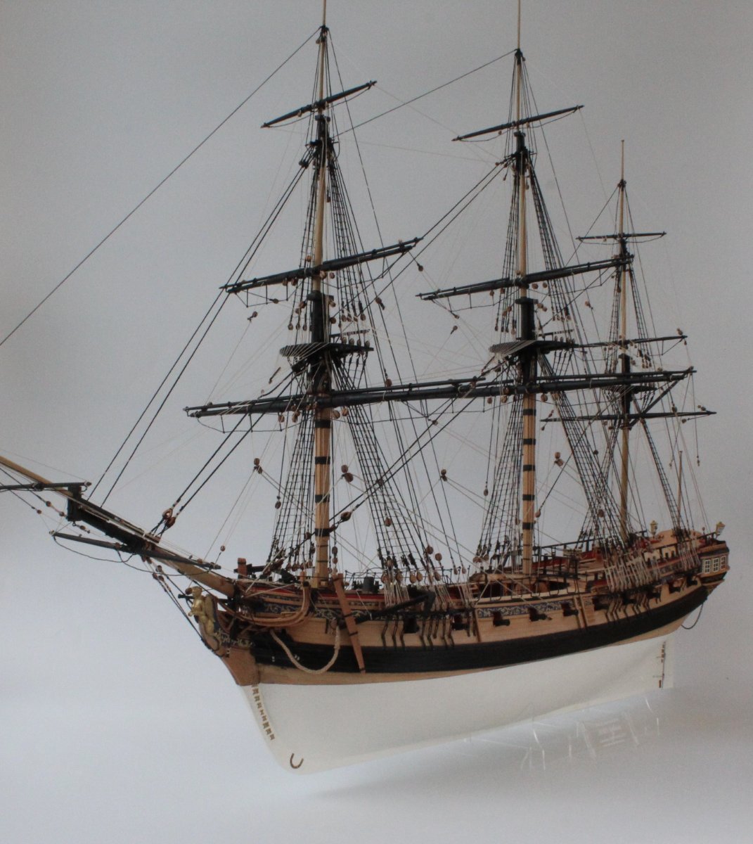
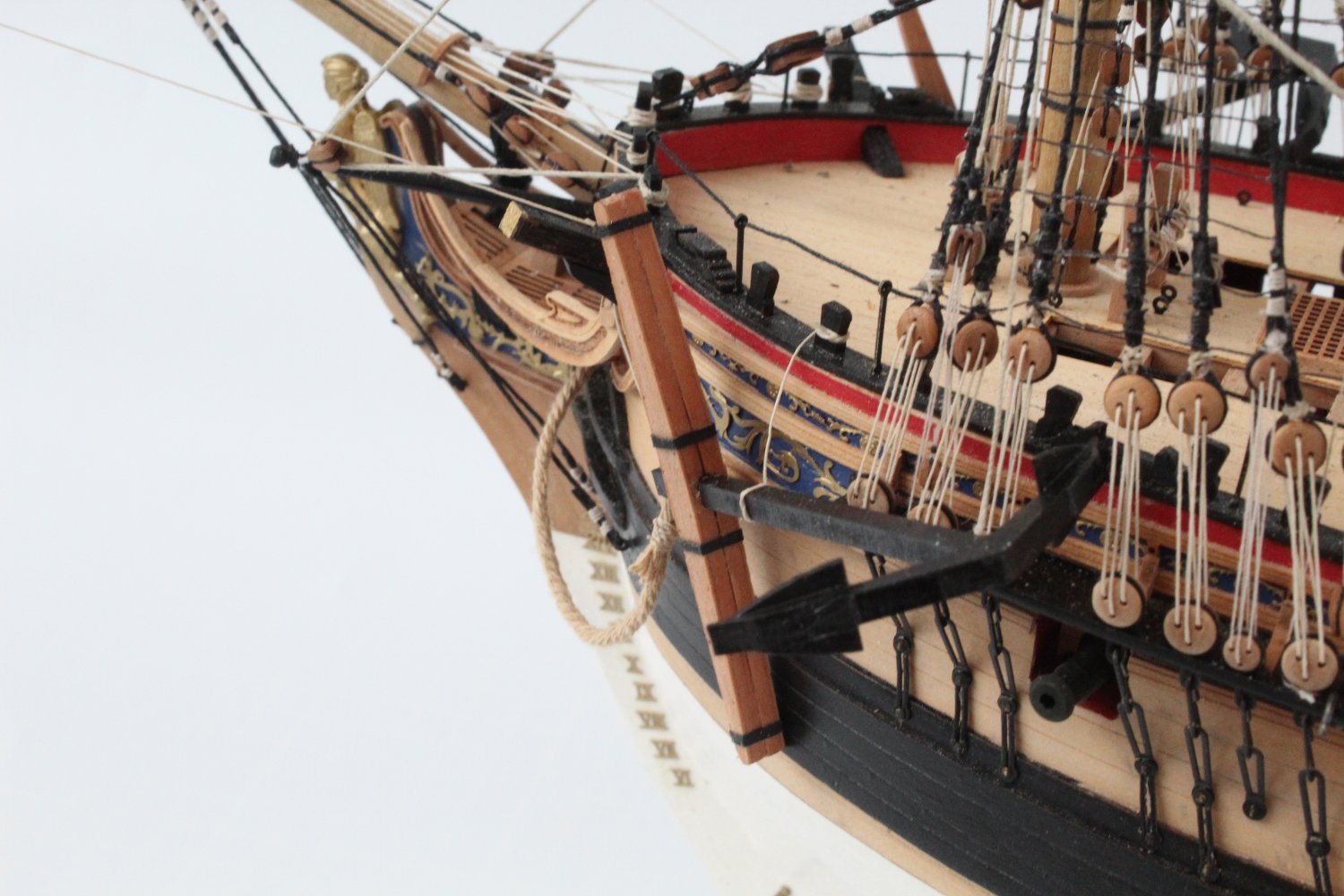
Build Completed
The final task was to assemble and add the anchors to the hull. I did build the 4 off supplied anchor assemblies, but I decided to only fit the two leading ones for this build.
I have really enjoyed building the Sphinx and I have learnt a lot of new skills during the construction of this beautifully designed model. Many thanks to @chris watton and @James H for their invaluable support and advice during this project. I have also really appreciated the support, comments, advice, etc. from everyone who has been following my progress, so many thanks to you also.
I have now cleaned the shipyard and will be starting another build very soon. This will be the Erycina. I have created a build log for this (Erycina Build Log) to record by progress.
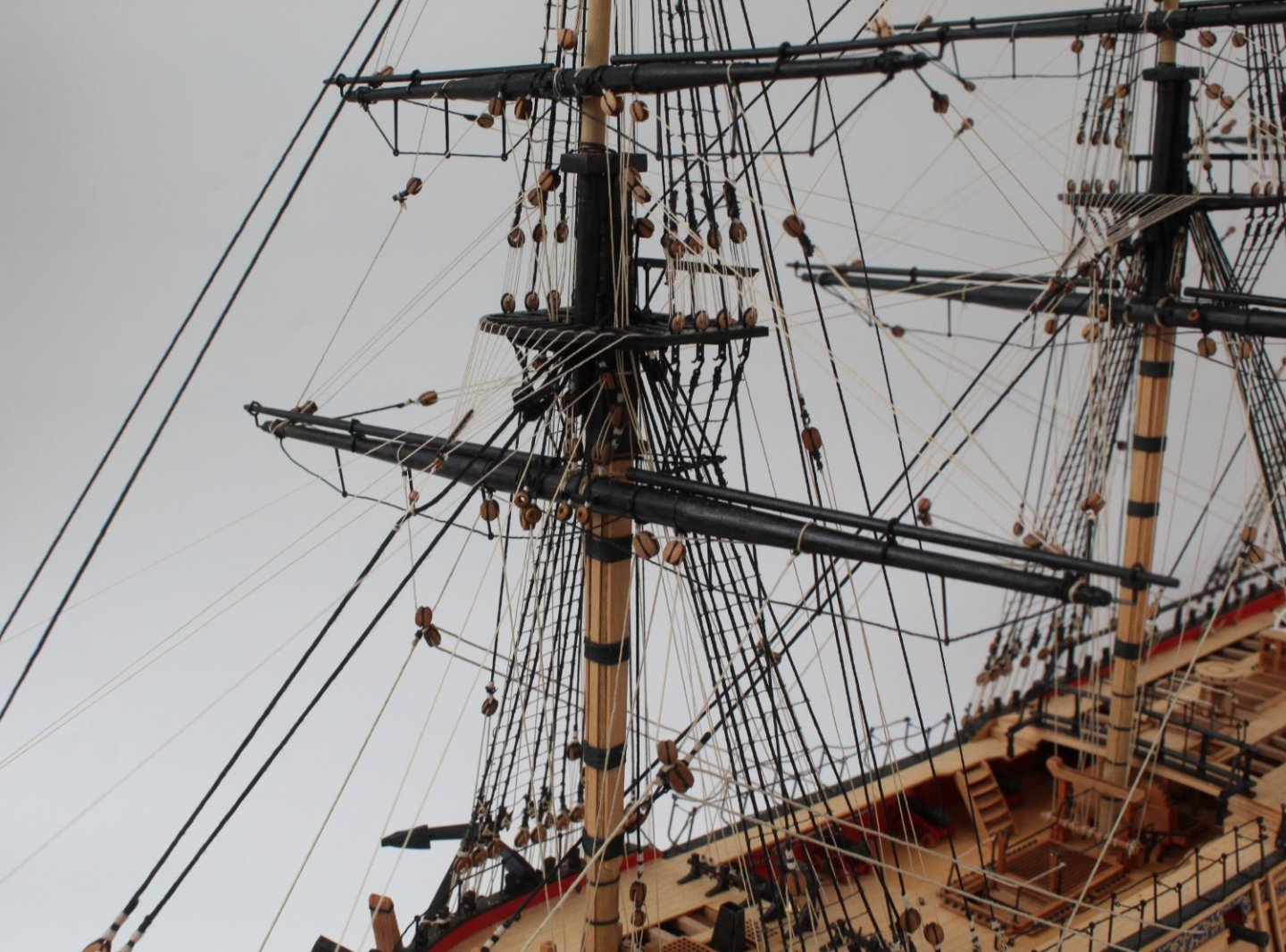
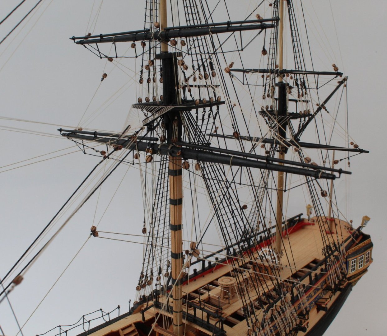
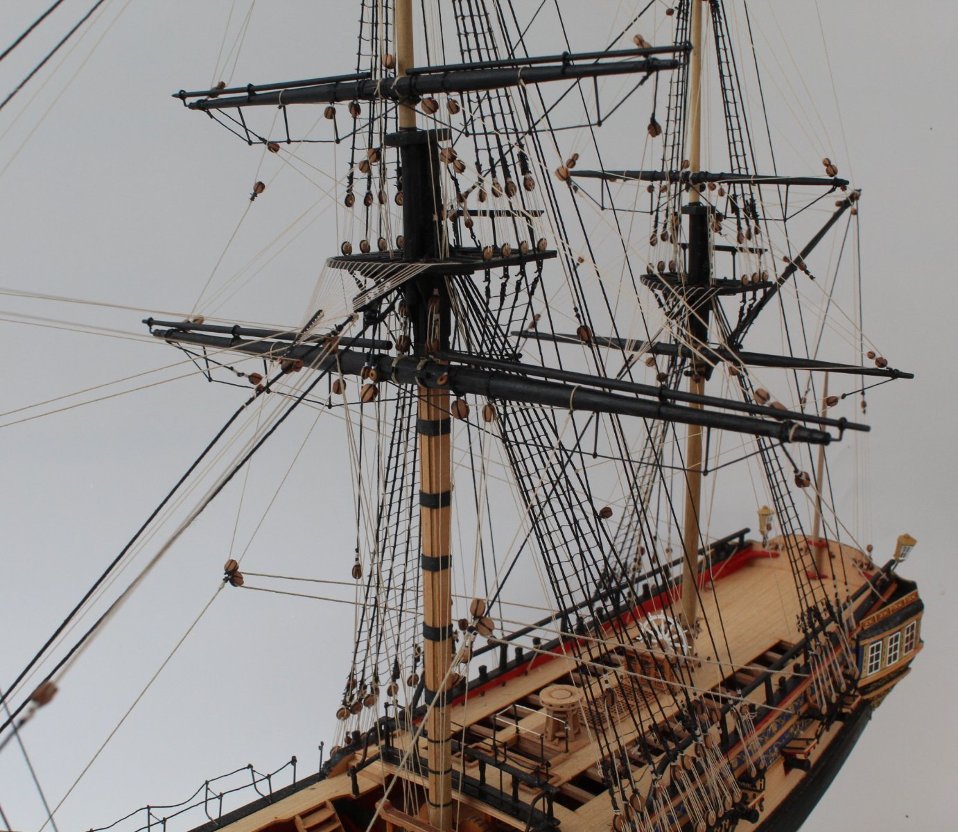
In no particular order I have taken a few photos of the completed Sphinx for you all to enjoy.


-
I am ready to start work on building the Erycina. I am really looking forward to this build project, which will be my 6th Vanguard Models kit build.
I will post regular updates showing my progress, along with photos. I will also detail some of the build processes I normally use to complete the more complex constructional aspects.
-
I use a 50 / 50 mix of white spirit and ronseal clear poly matt varnish. This is wiped on with a cotton cloth.
You've done a great job on the mast and yards, etc.
-
-
-


HMS Sphinx 1775 by Glenn-UK - FINISHED - Vanguard Models - 1:64 - V2 Kit by Glenn Shelton
in - Kit build logs for subjects built from 1751 - 1800
Posted
Thanks