


Glenn-UK
-
Posts
3,004 -
Joined
-
Last visited
Content Type
Profiles
Forums
Gallery
Events
Posts posted by Glenn-UK
-
-
-
Main Yard
I have made quite a bit of progress with the main yard manufacture over the last couple of days. With the help of the proxxon mini lathe chisel set it was a much quicker process to shape the main yard. I was very happy with the end result. I even managed to make the central section octagonal


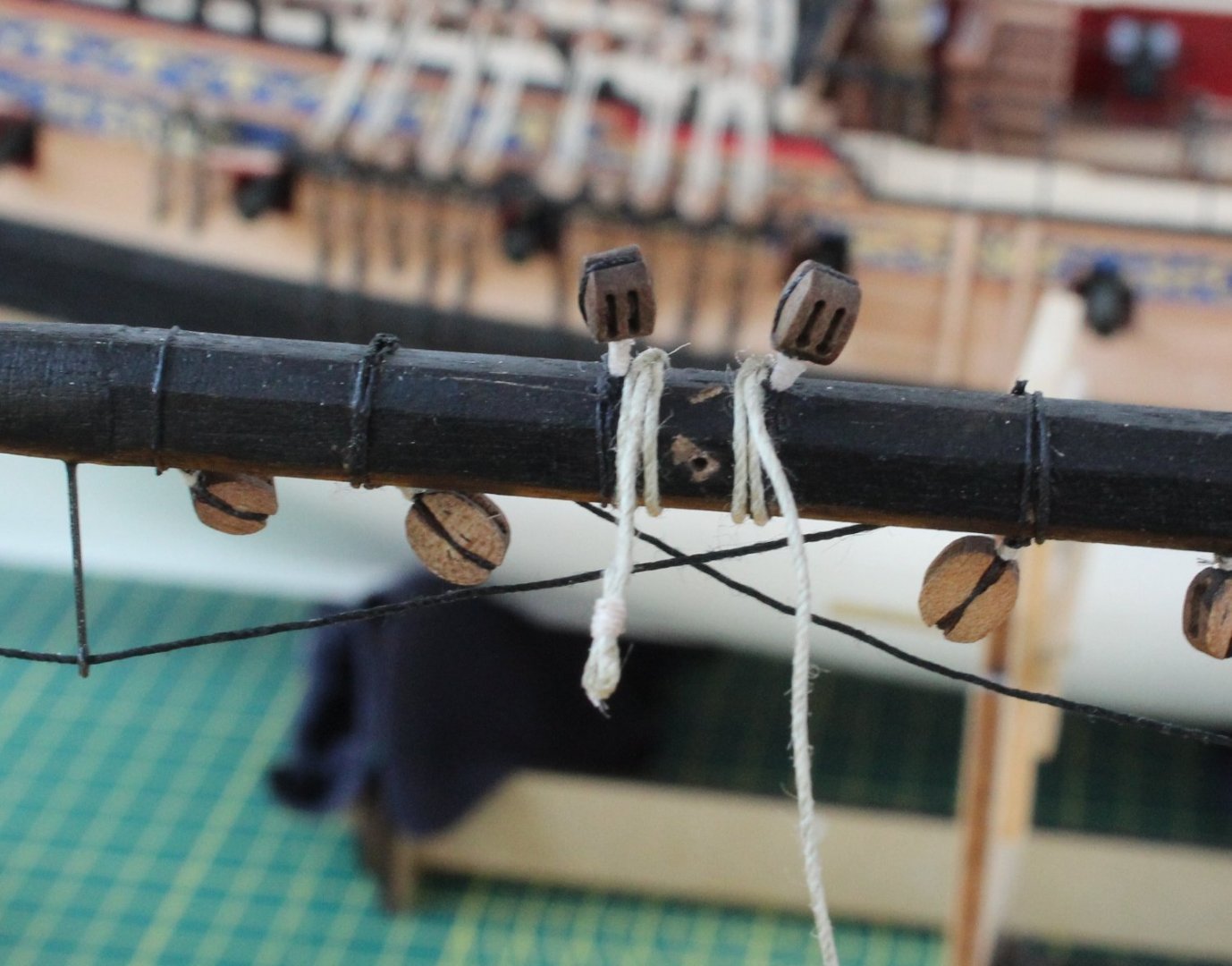
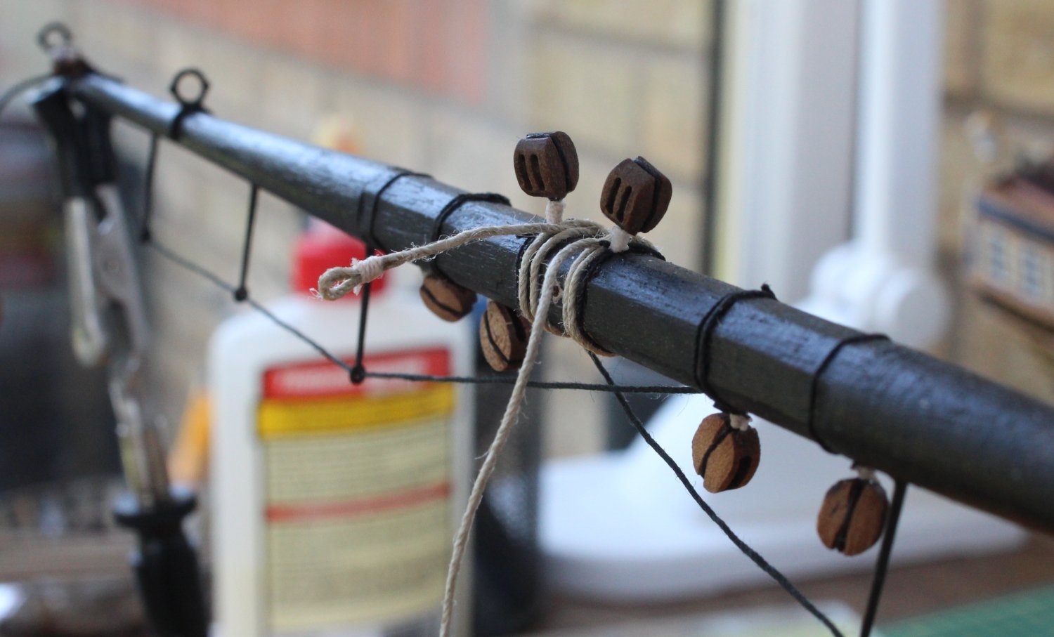
The next task is to add the various blocks for the jeers, tacks & sheets and braces. I have assembled the various blocks which are now ready and waiting to be seized.
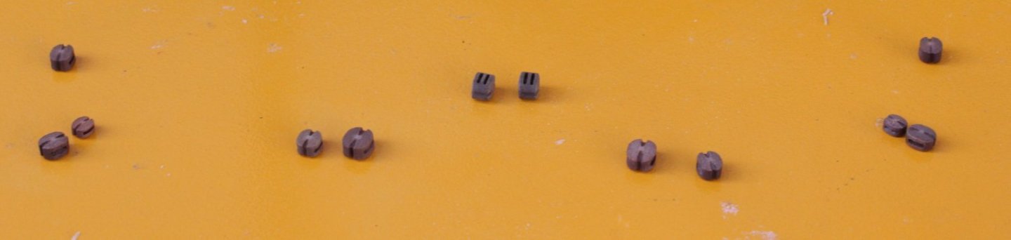
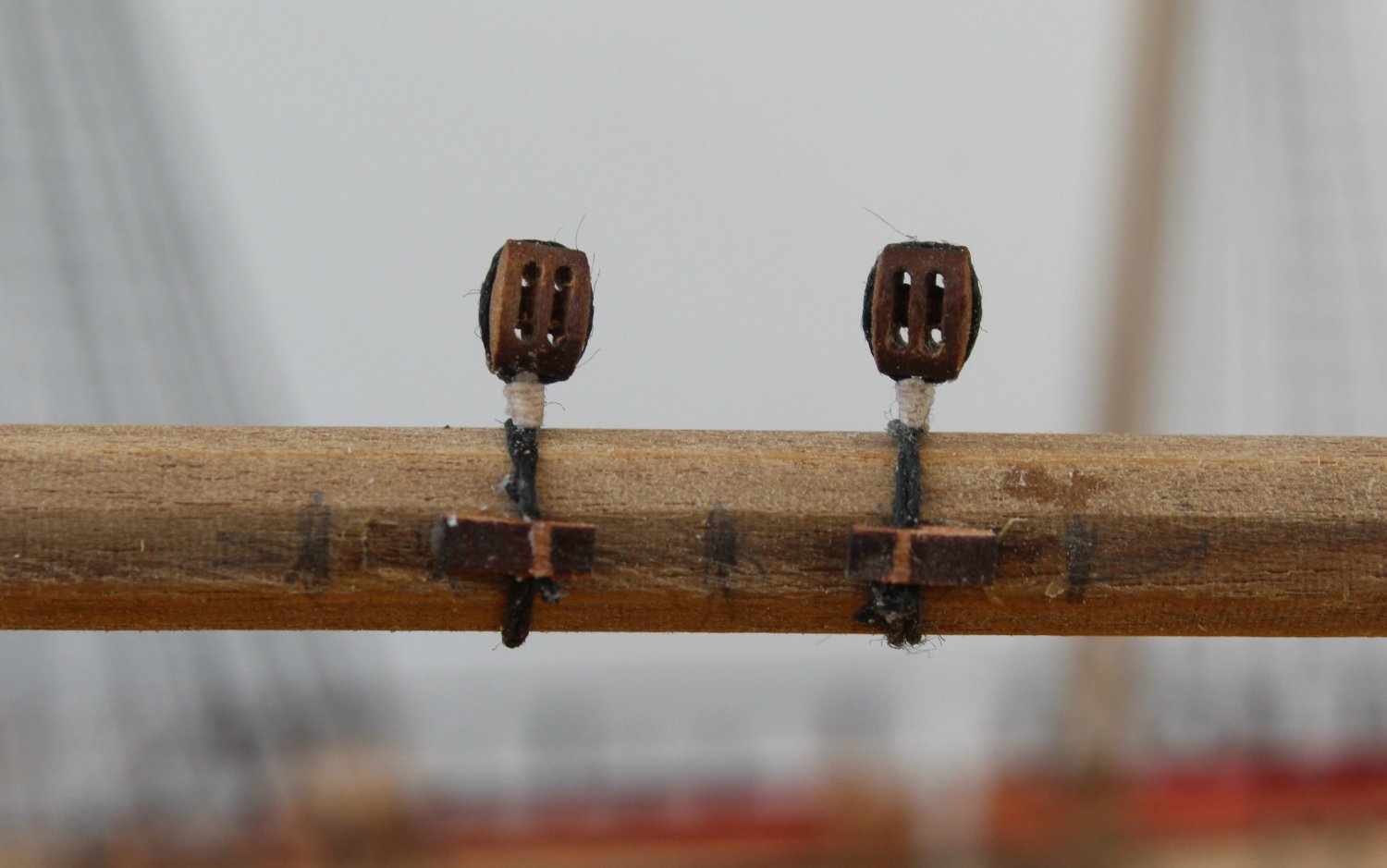
I started with the jeers, noting there are two parts per side. These comprise 5mm double blocks and the completed jeer sets are shown below.
I decided to add the 2 jeers blocks to the yard before moving on to the next set of blocks.

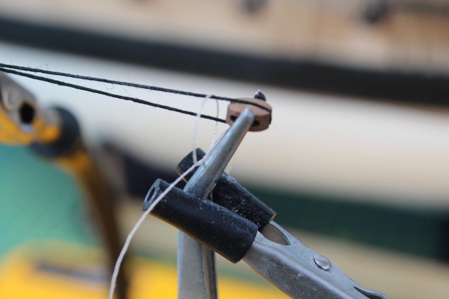
The quad hands are a really useful tool to support the yard as the blocks are being added, as shown below.
There are three block sets, per side for the sheets and tacks. I am using the bottom / top arrangement of half hitch knots for seizing the blocks. With the block held in the quad hands I start by adding a bottom half hitch knot, as shown below.
With the bottom half hitch in place I repeat the process by adding a top half hitch knot.
For most blocks I add a total of 6 bottom and 6 top half hitch knots and the seizing can be easily adjusted so it sits tight up to the block before the ends are secured with ca gel and trimmed. In the next picture the seizing is ready to be trimmed.

The finished block is shown next.
When there is a double block arrangement I will only add three top and bottom half hitches to the first block. The picture below shows the arrangement I use with the quad hands when adding the second block.
And the next photo is the end result.
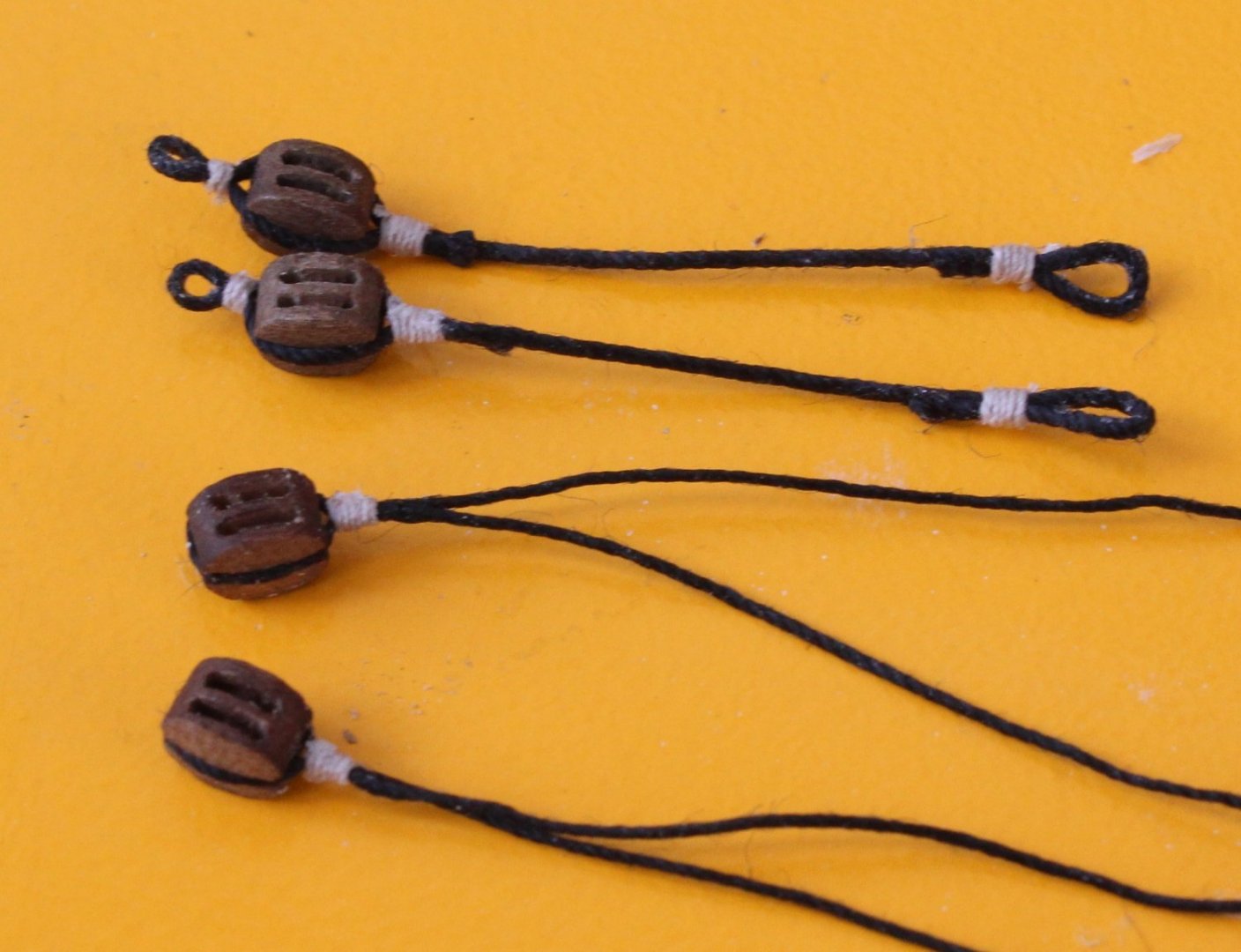
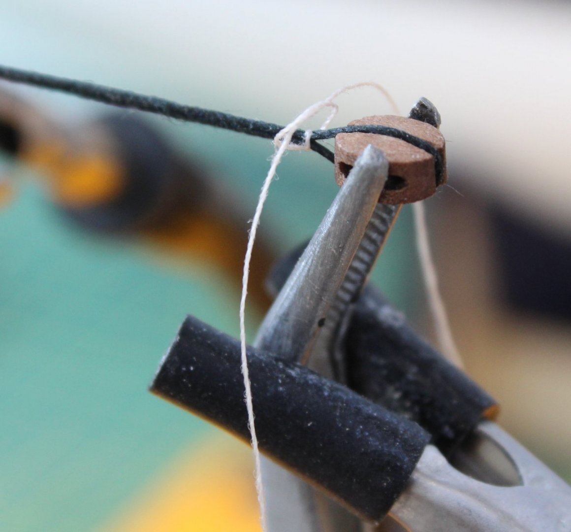
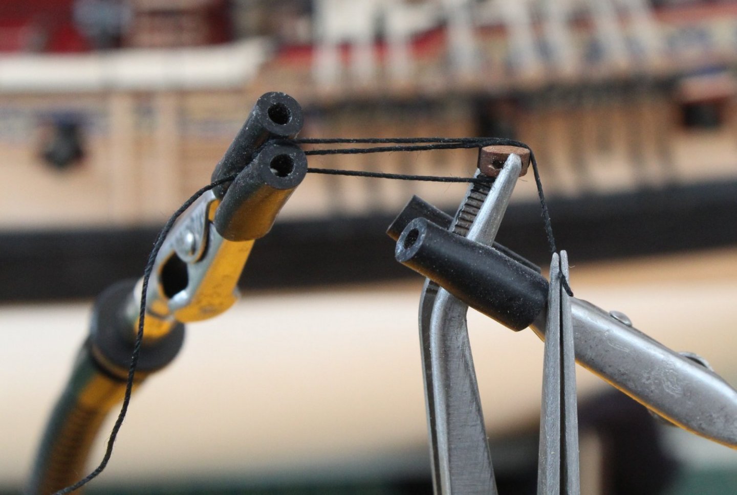
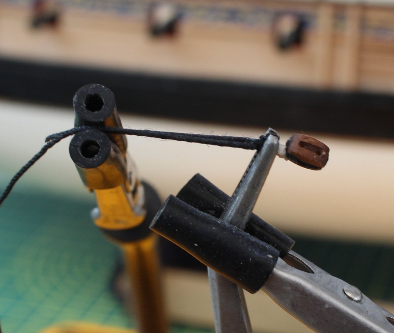
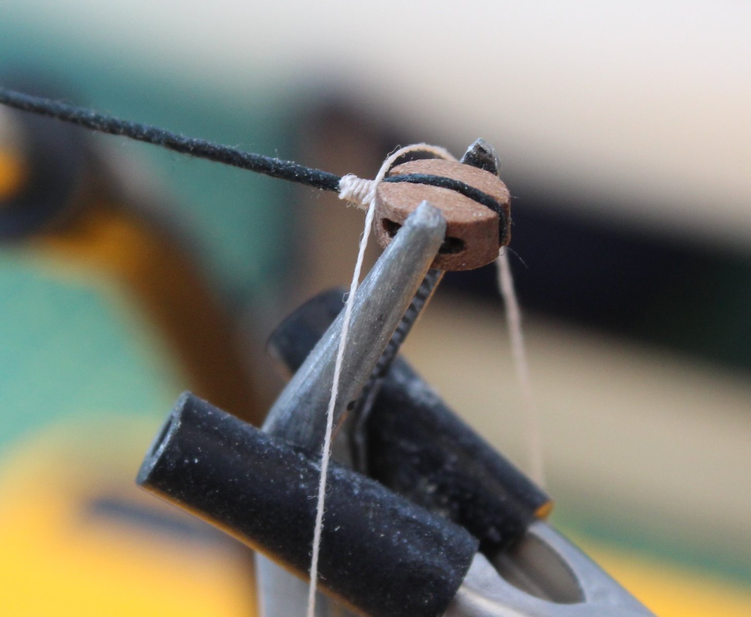
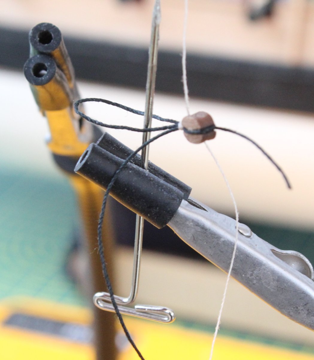
The final task is to seize the two brace blocks which, according to the plans, requires a thimble (eyelet). After a little bit of thought I have refined the process I use to create the required thimble. I start by positioning the block in the quad hands as normal. I then take one free end of the thread back over the block which is held in place with my reverse action tweezers. The next picture shows this arrangement.
After the seizing has been added the looped end is place over a suitable round object, in my case a metal pin, as shown below.
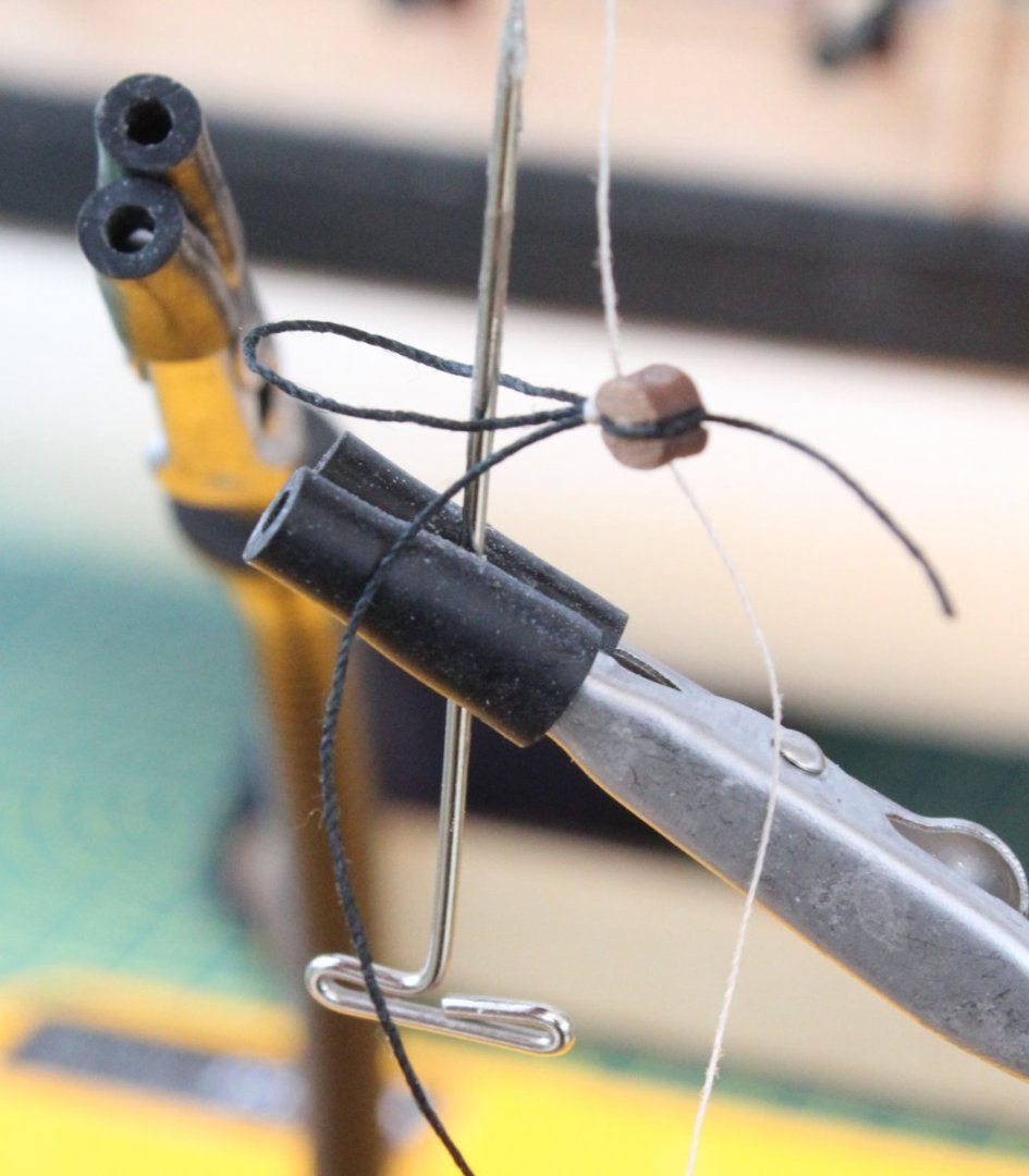
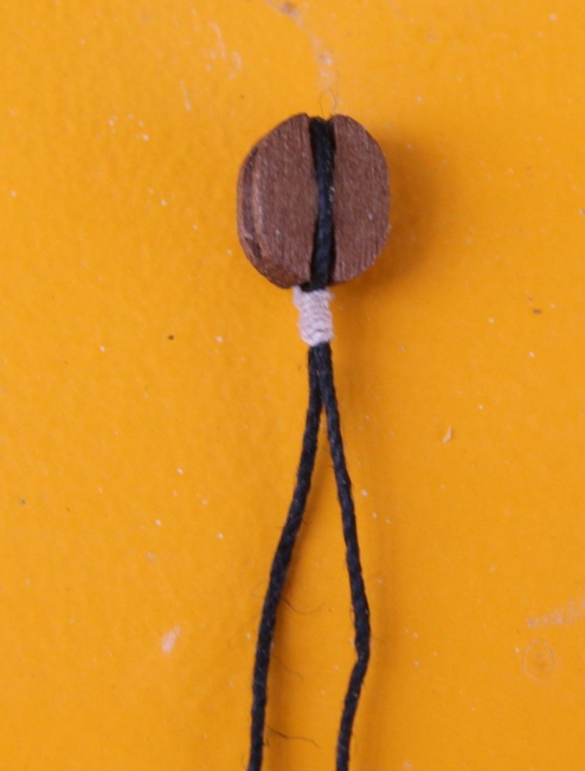
The looped end can then be pull tight over the round pin before the seizing is secured with a touch of ca gel and the excess seizing thread is removed. The block has been gently lifted off the metal pin in the picture below.

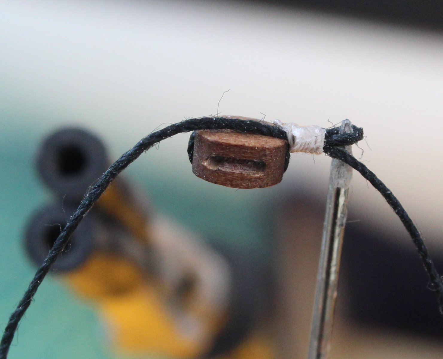
The remaining free ends of thread can be trimmed as required to end up with a nice looking block complete with a thimble eyelet.
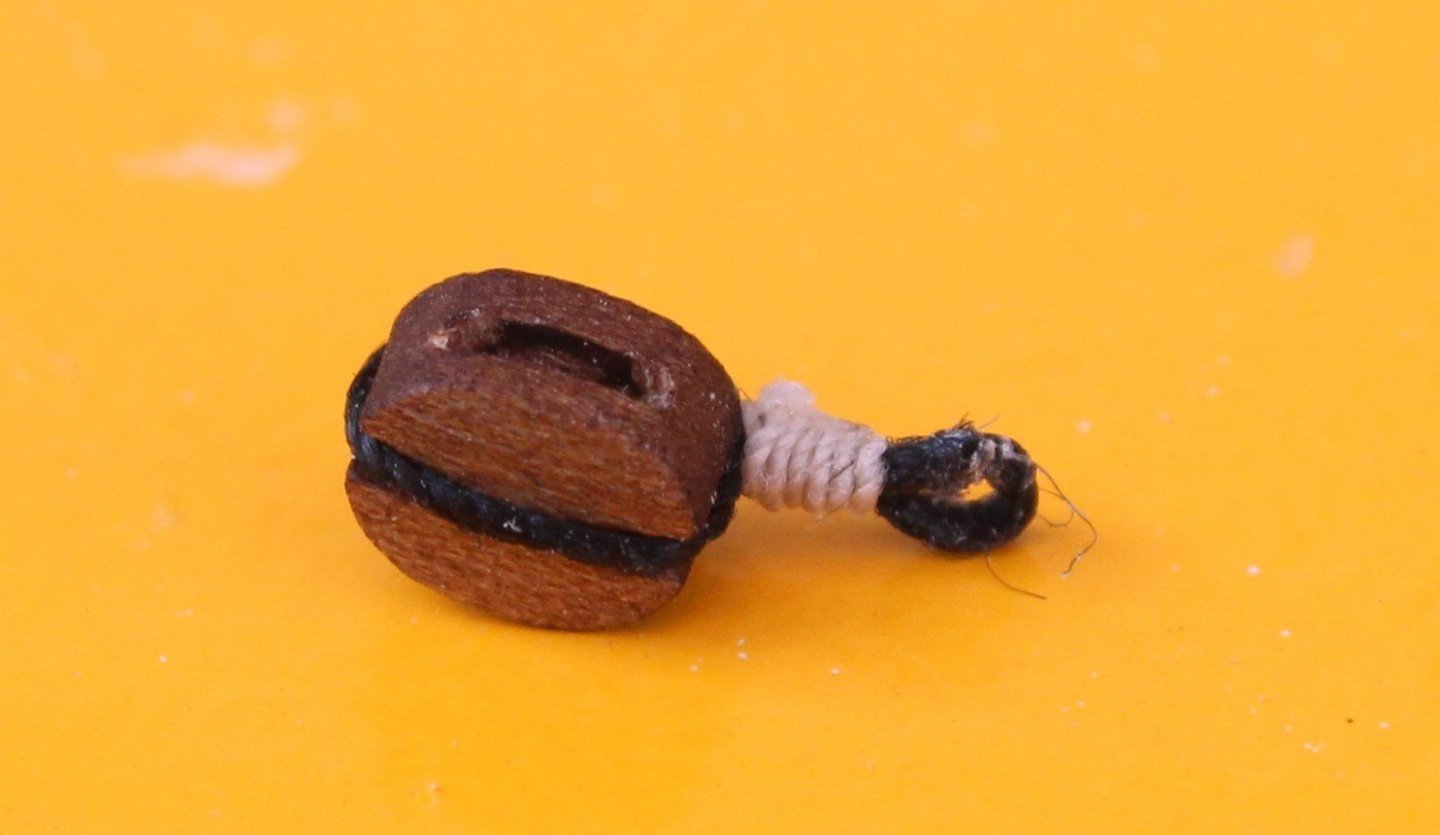
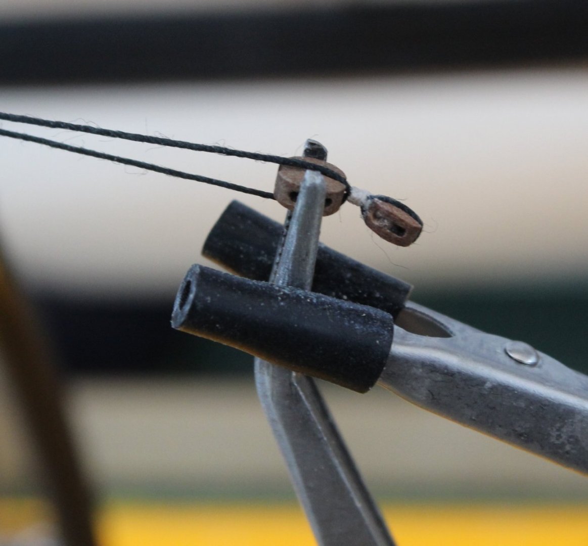
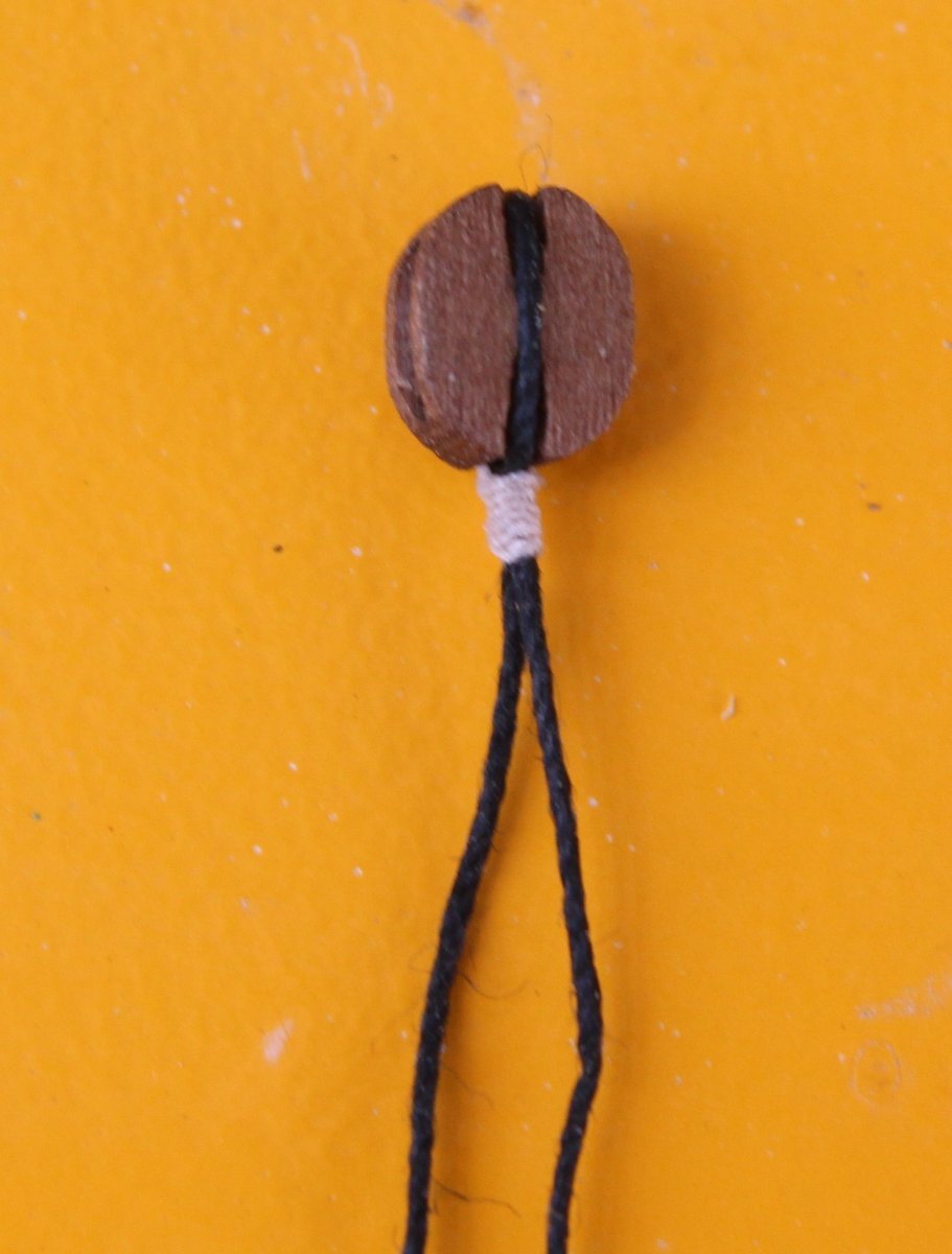
To complete the brace block a length of 0.75mm black thread is fed through the thimble and is then placed in the quad hands ready to be seized. This is shown in the next photo.
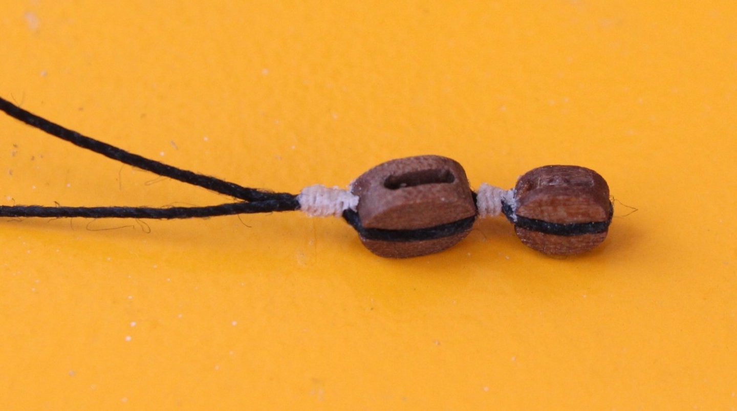
One of the two completed block for the braces is shown below.
With all the blocks seized they are now ready to be added to the main yard.
-
Due to the really nice weather for the last two days I have been outside doing some gardening and sunbathing.
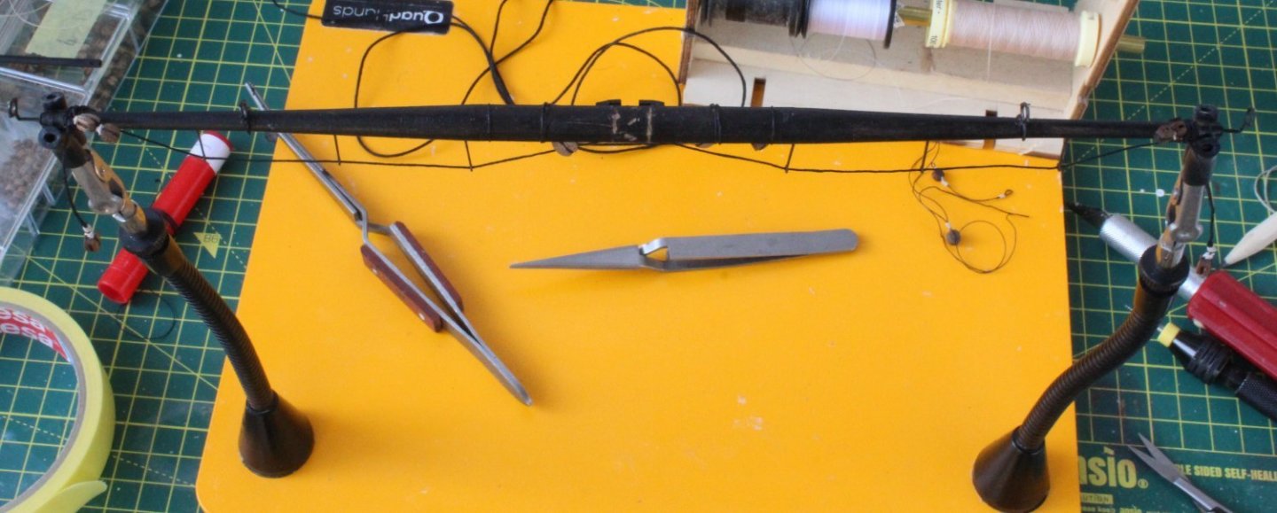
Today I received a new set of tools which will complement my Proxxon mini lathe.
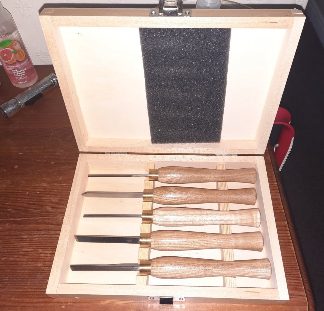
I plan to try them out tomorrow, unless its another hot 🌞 day. I think these will help me tremendously with manufacturing masts and yards.
- Rustyj, Dave_E, GrandpaPhil and 2 others
-
 5
5
-
Looks like you're doing a great job on your build.
- Dave_E, usedtosail and Keith Black
-
3
-
I have has a look at my completed build and the my mizzen mast rake angle looks good and as far as I can tell it matches what is shown in the manual and plan sheets.
- Keith Black and DocRob
-
1
-
 1
1
-
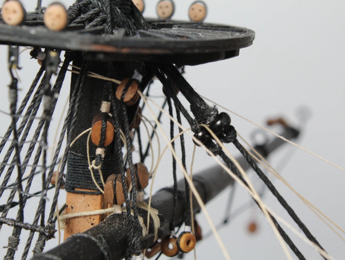
Crows Feet - Foremast
I experimented this morning with trying to secure the free end of thread using a knot which could be positioned uptight to the underside base of the platform. I was using a basic half hitch but after several attempts I decided it was an impossible task and I was ready to ask for help.
It then occurred to me there must be another way to do it such as using a slip knot. After a quick lesson (via the internet) on how to tie a slip knot I tried one on my test arrangement which was simply a spare platform part held in my quad hands. Once I had mastered how to tie the knot it became apparent I would be able to adjust its position to the underside of the platform base.
Turning my attention to the free end of thread from the foremast crows feet rigging I tied a slip knot. Next I adjusted the tension in the crows feet rigging lines and once I was happy with how it was looking I was able to move the slip note into the required position. I then applied a touch of ca gel to the knot and cut away the excess thread.

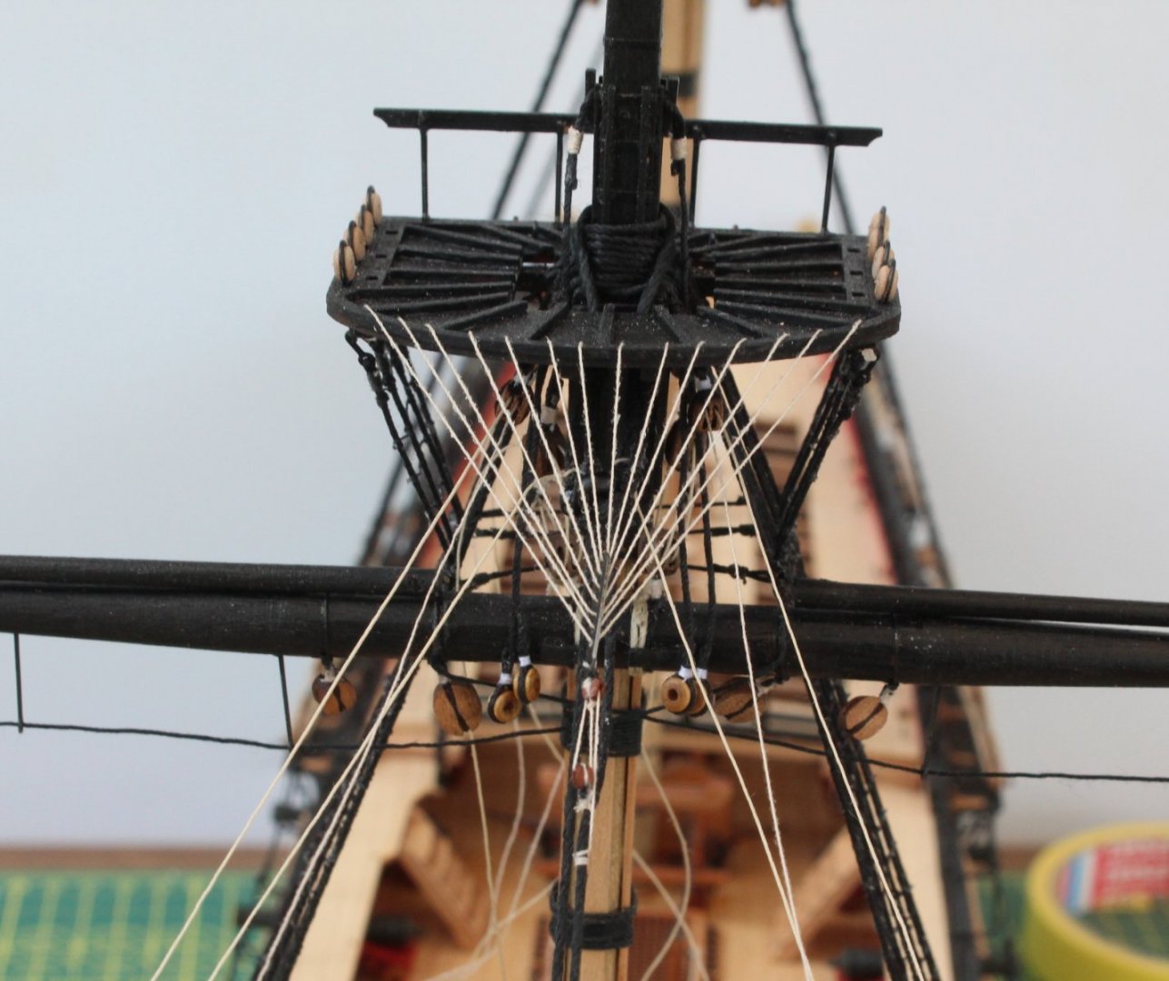
Using the same test set up I added a belying pin to the platform and I was able to replicate securing a free end of thread to a belaying pin. Of course it is much easier to do when there is nothing in the way to hinder access. That said I have found a method which seems to work and looks good.
- mtaylor, BenD, Blue Ensign and 7 others
-
10
-
Planning Next Stage
With the fore stay and preventor rigged the next logical task would be to add the main yard and then the main stay. I have not, as yet manufactured the main yard.
The main yard is 295mm long and made from a 8mm dowel. The central section of 76mm is octagonal in shape. The yard is then tapered down to 3.5mm over the remaining 105.5mm per side. For simplicity I plan to taper only the last 100mm per side, i.e. 8mm down to 6.9mm for the first 25mm then from 6.9mm down to 5.8mm over the next 25mm, down to 4.7 over the next 25mm and finally down to 3.5mm over the final 25mm.
Up and till now I have been using my proxxon mini lathe with 80 to 120 grit sandpaper to add the tapers. This does produce the desired results but can be quite time consuming, especially when tapering a 8mm dowel down to 3.5mm. I have been contemplating buying some proper wood turning tools for some time as I believe I can achieve much better results and should also speed the process up somewhat.
As I have £75 of unused Amazon vouchers I decided to bit the bullet so today I purchased a set of proxxon tools for turning (27023). The set comprises a 3mm spindle gouge, 6.5mm square and round end scrapers, 6.5mm skew chisel and a parting tool with a blade with of 2.3mm. These are being shipped to the UK from mainland Europe so will take a few days to arrive. I will use these tools to shape the remaining yards for the Sphinx. I do have some spare material available to experiment with the tools before I start work on the tapering the actual yards.
While I wait for the delivery I have been pondering what I can do. There are a couple of techniques I wish to get better, such as securing a free thread end to a belaying pin. Currently I have 6 free ends which require belaying which I would like to get done ASAP. I plan to construct a test bitt rack complete with some belaying pins and I can then spend some time trying to perfect the method before I belay the free thread ends on the Sphinx.
With my previous builds with crows feet I have never been able to get the final knot tight under the platform and have resorted to using ca gel to hold the thread in place. As I have some spare platforms left over from my aborted V1 build I will try work out a method to pull the final knot tight. I am not sure if there is a special knot I need other than a standard half hitch.
I am also tempted to fit the fore topmast and to then rig the shrouds and ratlines.
-
Foremast Crows Feet Rigging
The repairs to the bowsprit rigging were made yesterday. I inadvertently sniped one of the undamaged spritsail top braces threads during the repair process which also had to be replaced.
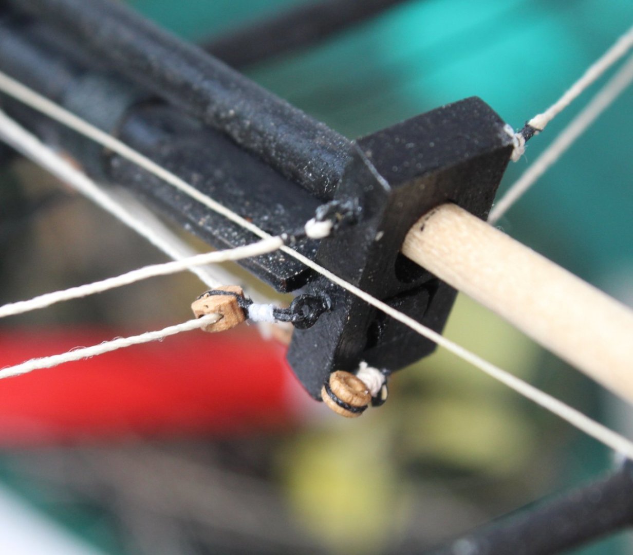
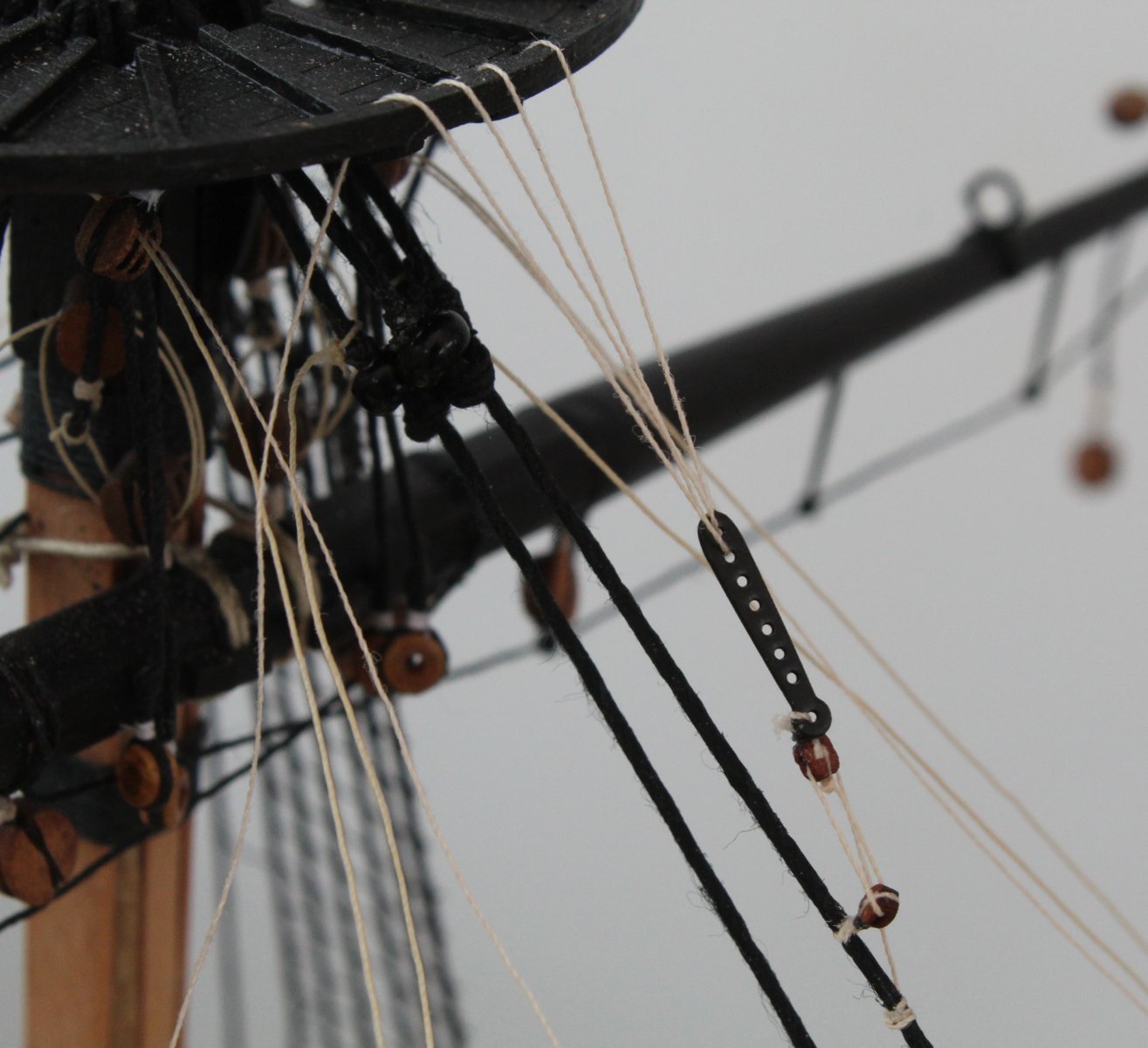
Today I was able to start work on the foremast crows feet rigging. I seized some 0.1mm natural thread to 2 x 2mm single blocks along. I then seized the foremast euphroe block to one of the 2mm blocks. Next I checked that it would be possible to feed some 0.1mm natural thread through the 2mm blocks, as can be seen in the photo below.
With reference to the rigging plans I attached the first 2mm block to the fore preventor stay. It was very fiddly work for my big hands but it only took a few minutes work to complete. I am aware the lines look fluffy. I did not apply beeswax to the lines beforehand. The fluffy nature of the lines is only really noticeable (in my view) when taking close up pictures.
A longer distance view of the first 2mm single block in place on the preventor stay.

I then added the rigging between the two blocks and the free end was secured to the fore preventor stay. Again this was fiddly work.
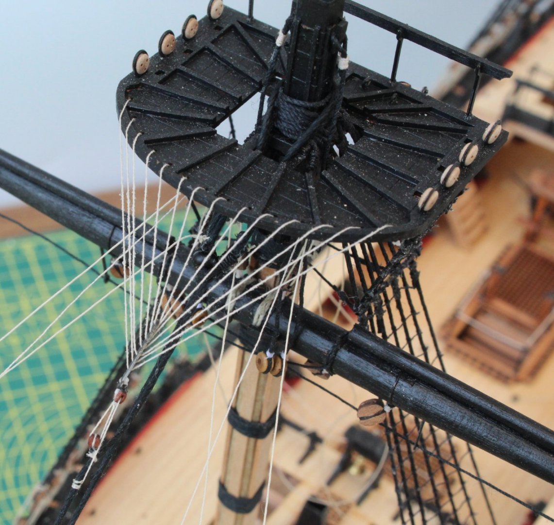
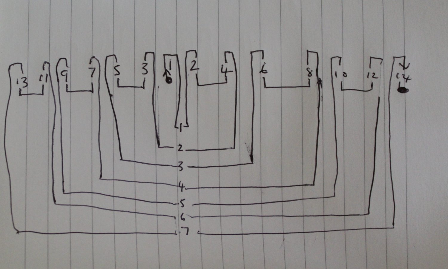
It was now time to add the crows feet rigging. Just to make sure of the sequence I drew a rough sketch which shows the 14 holes on the platform and the 7 holes of the euphroe block. It is just a simple case of starting at position 1 on the platform and tracing a route until the line has passed through all the holes. The following photo shows my rough sketch
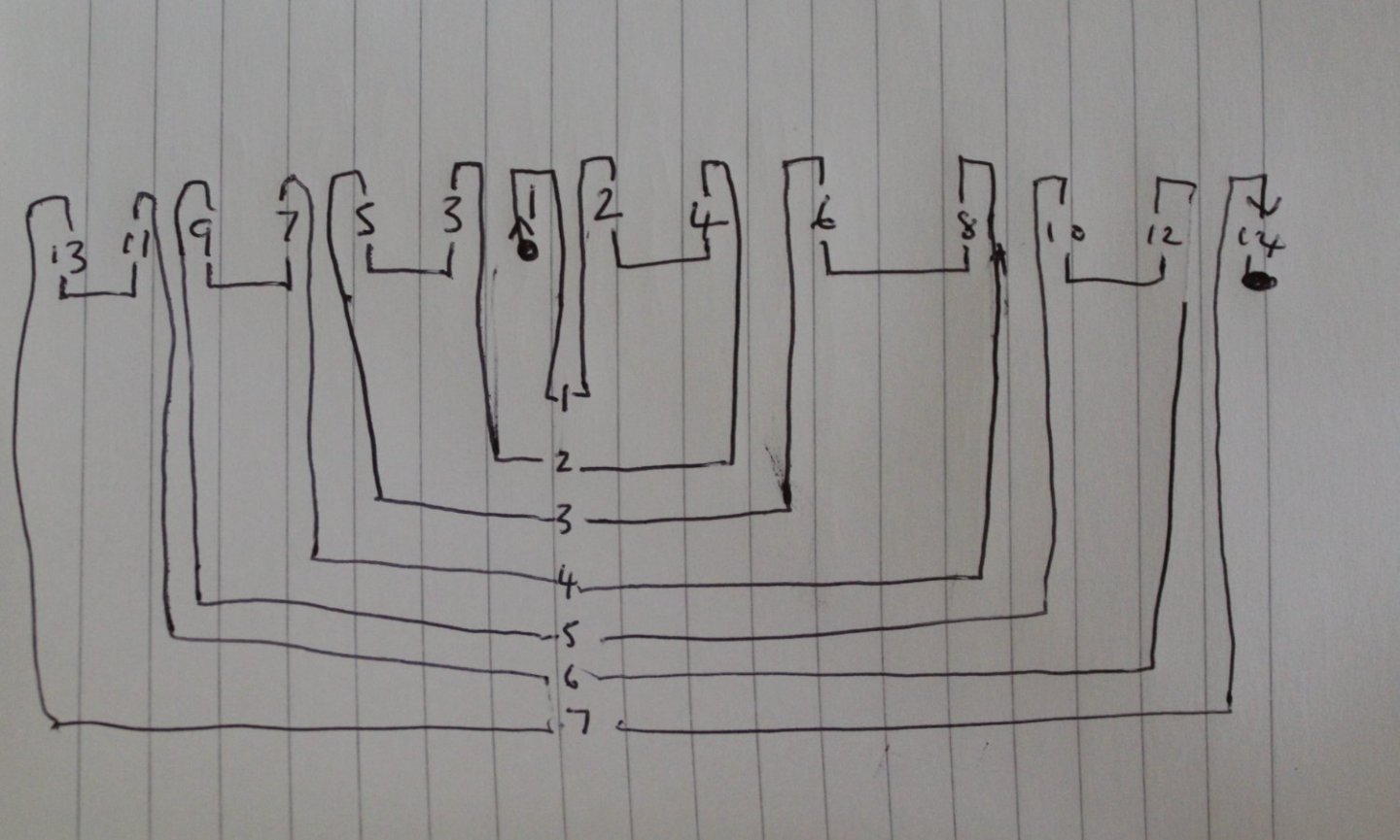
The distance between the euphroe block and the platform is around 6cm on average and there would be 14 runs required between them. This equates to a total run length of 0.84m. I therefore decided to cut a 1m length of 0.1mm natural thread just to be on the safe side. With a knot added to one end I started to feed the thread, as shown in the photo below.
I am not totally happy with how the euphroe block looks. It is to tight with the 2mm block (and not very flexible) so I may decide rework it but I would prefer not to so for the time being I will leave it as is.
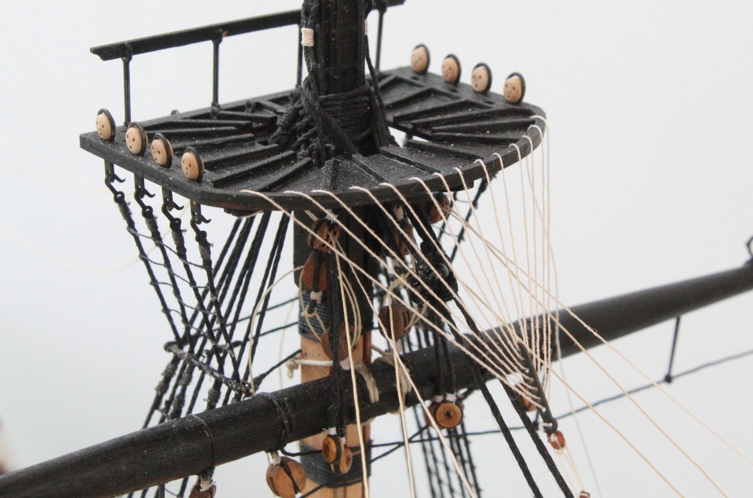
I did find it tricky feeding the thread through the platform hole from the underside but with a steady hand, good eye / hand coordination and a bucket load of patience I did manage to do it. Sometimes it took me a few goes (<10) and sometimes it took me several goes (>20). On a couple of occasions, when the free end became a bit bending, I found it necessary to trim and to then reapply some ca gel to stiffen the end back up again.
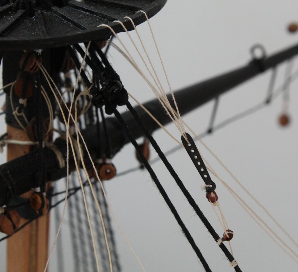
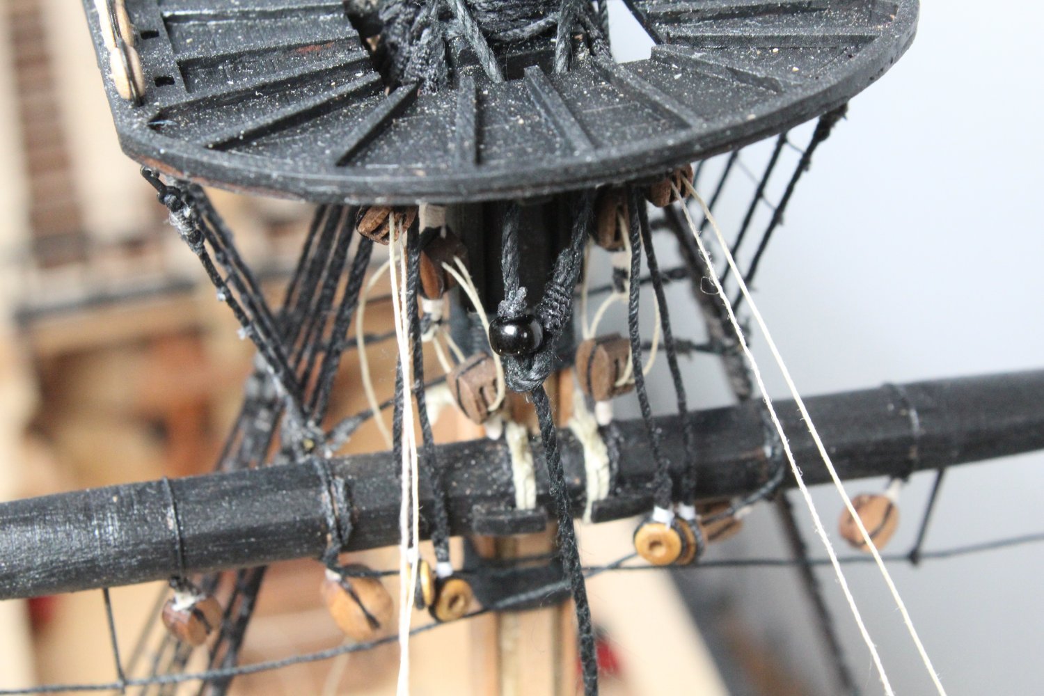
The crows feet is now fully rigged. I will spend a bit of time adjusting the tension in the lines before I tied off the free end which I can do a later stage. The euphroe block is not perfect but I think I will leave it as is.

- scrubbyj427, GrandpaPhil, Thukydides and 9 others
-
10
-
 2
2
-
In my last post I indicated that I made a repair to a block fastened to an eyelet on the bowsprit end cap. Sadly my repair failed when I noticed there was no tension in the rigging line. On closer inspection the block was no longer attached to the eyelet. I have therefore removed the rigging and will redo it again.
Also I made a fatal error when trimming the spritsail braces which meant they had to be removed and will be redone.
- mtaylor, Theodosius, Dave_E and 1 other
-
4
-
Fore Stay and Preventor
It has been a productive morning. I noticed one of the blocks that had been rigged to the bowsprit endcap eyebolt had become detached. My first thought was I would had to derig the line and redo. On closer inspection I decided there was a simple work around solution which after about 5 minutes work meant the block was securely retied to the eyelet. Using a needle I was able to pass some new thread through the gap between the seizing and the end of the block. The new thread was then fed through the eyelet of the endcap and tied off.
The photo below shows the good side, which did not need the repair.
The next photo shows the other side where the repair was made. It will take an eagle eye to spot this on bodge job repair once the ship is fully rigged.

Once the repair was complete I added the 6mm closed heart block to the fore stay. As I started to add the lanyard I noticed the seizing on one side of the forestay open heart block on the bowsprit had started to unravel. I knew it would be a major job to remove and re rig as it would also affect the bowsprit shroud rigging. With some gentle cutting I was able to remove the thread that had worked lose. I was then able to apply some new seizing. Once again it is not a perfect repair but it will be had to detect once the ship is fully rigged.
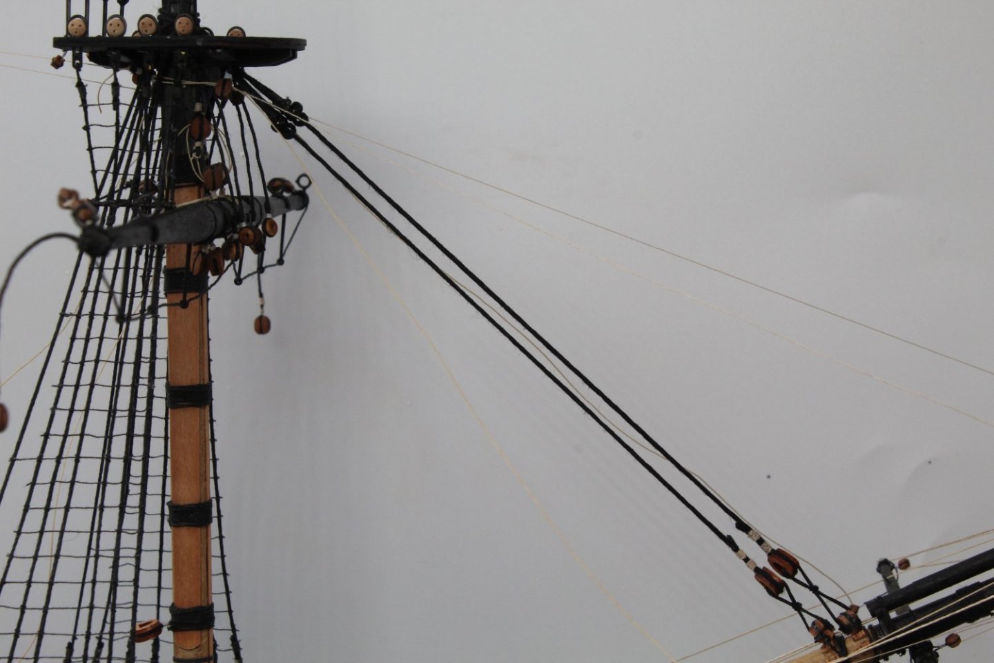
With the open heart block repaired I then added the lanyards for the fore stay which is shown in the picture below.
The following is a picture of the competed forestay.
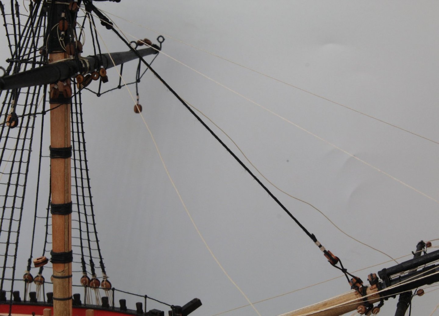
With no more repairs required I added the closed heart block the fore stay preventor followed by the lanyards. The next picture shows the completed rigging for the forestay and preventor.
A close up of the forestay and preventor lanyards is shown below.
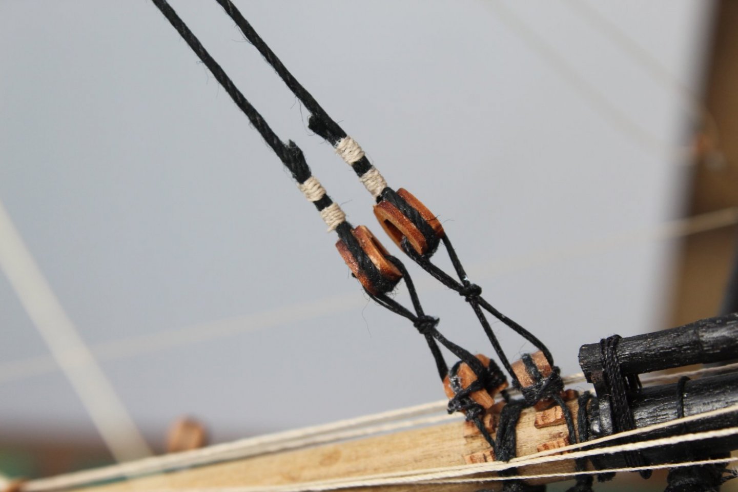
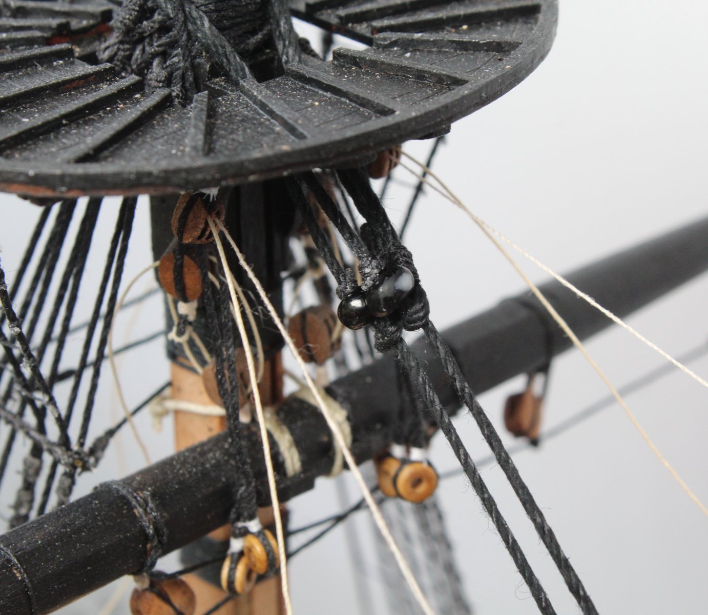
The mouse arrangement for both the forestay and preventor is shown below

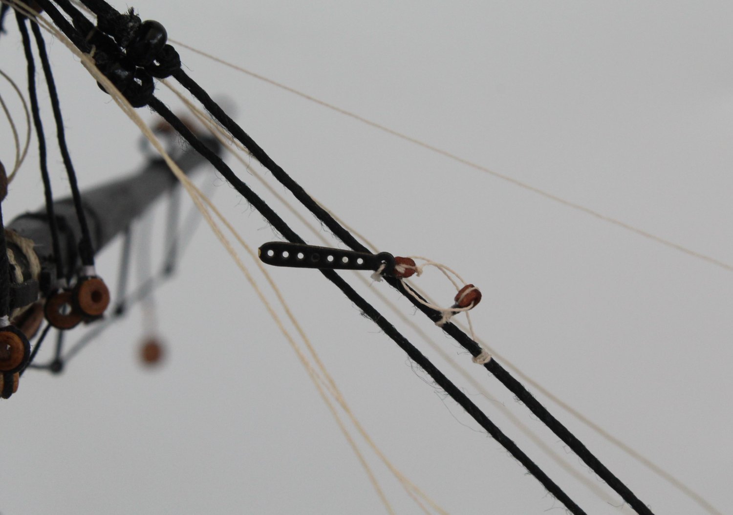
On final task was to feed the spritsail yard braces thread free ends over the foremast stay, above the mouse. If you look closely at the picture below you will notice the natural thread that is sitting on top of the lower mouse which is now waiting to be tied off.
I am now debating the next step and I leaning toward adding the foremast crows feet rigging next.
- Theodosius, DelF, mtaylor and 5 others
-
8
-
Foremast Take 2 - Update
Before I took the decision to remove the foreyard, due to the error I made in fitting the wrong sized double blocks for the jeers, I had tied off the brace threads to the spritsail top yard. I have not tied off the other end of these threads to their respective belaying point which will be done once the fore and preventor stays have been added. In the picture below I have used my reverse action tweezers to simulate tension on these braces.
With the truss pendants and jeer double blocks removed the foreyard is supported by the quad hands ready for the replacement truss pendants and jeer blocks to be added. I have also removed the pin as I wish to fit a slightly longer pin.
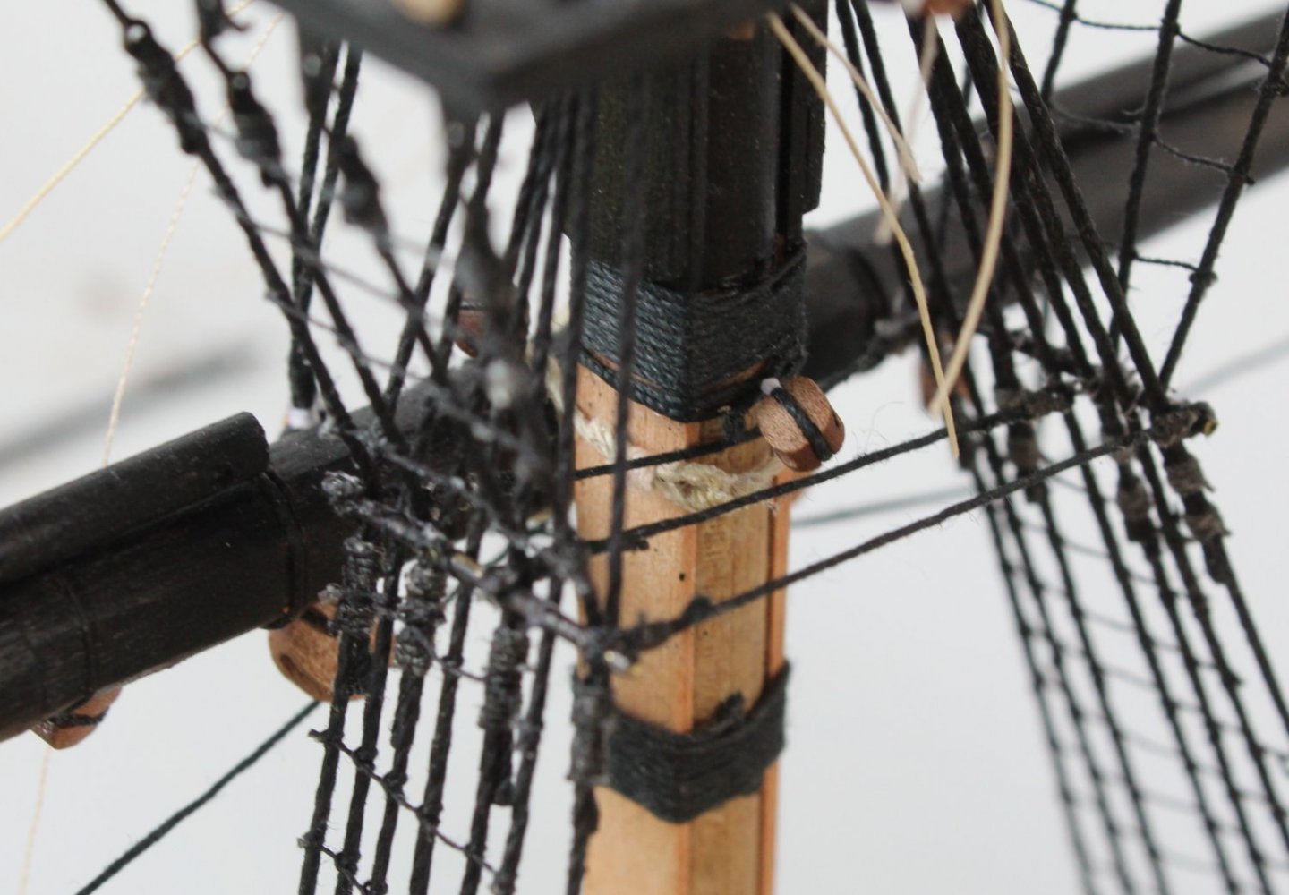
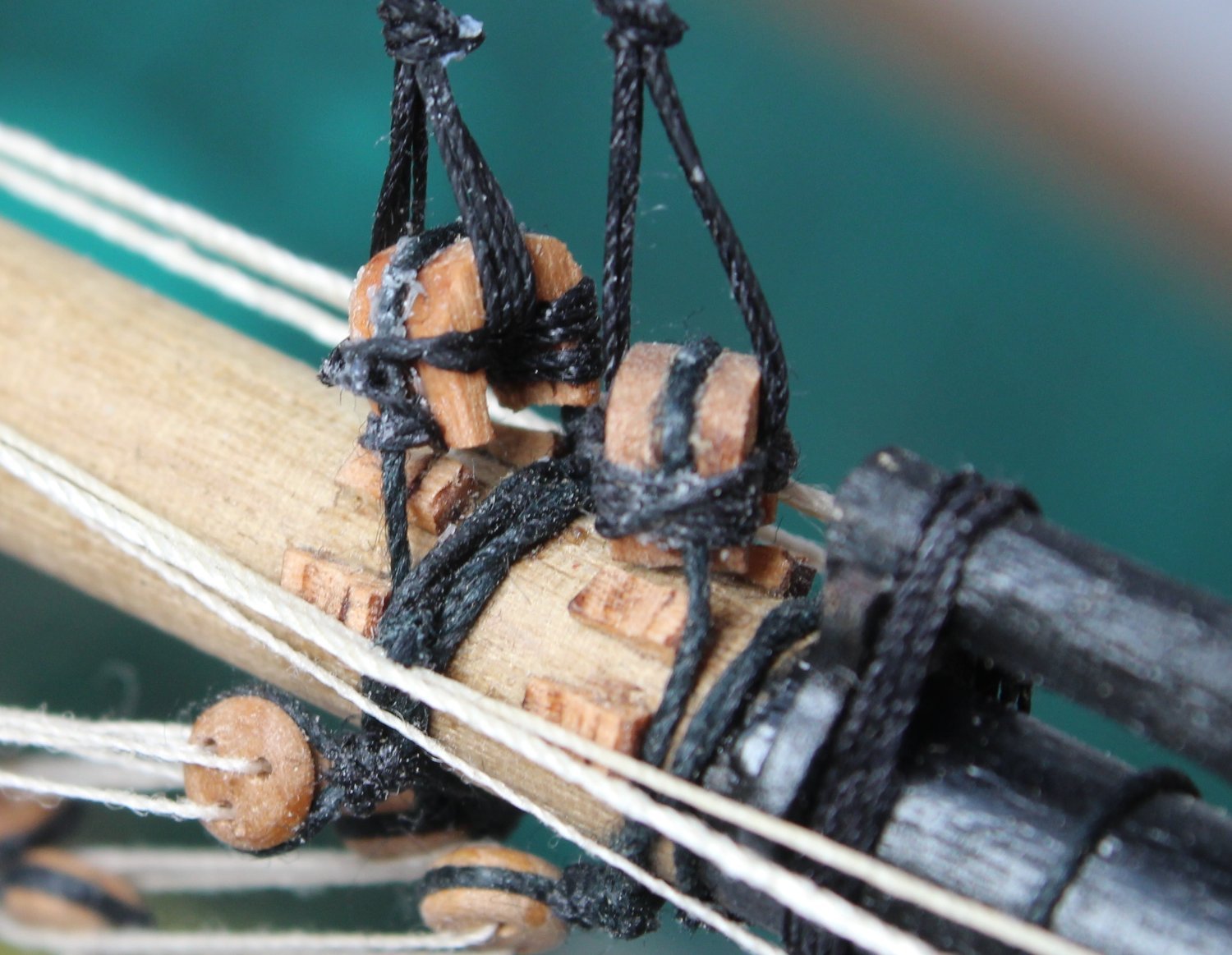
It did not take too long to fit the new jeer blocks and truss pendants. Once again I used clove hitch knots to secure the truss pendants.
The next picture gives a better idea of the truss pendant arrangement. One pendant is a short length with a thimble (eyelet) at the end. The other truss pendant the free end. Once the yard is pinned to the mast the free end is passed through the thimble and once pull tight to keep the yard in place it can then tied off using a simple half hitch knot. The knot is then secured with a touch of ca gel as I did not think it was feasible for me to add a proper seizing.

The foreyard (take 2) in place on the mast and looks good to my (wonky) eye. The foreyard booms have been removed for the time being.
Next I added the jeer rigging. It was so much easier with the right size blocks fitted to the foreyard and I am reasonably happy with how this looks. The free ends have been taken down to the deck but have not be tied off to their respective belaying points. I will adjust and tension the jeer rigging as necessary when it is time to belay the free ends.
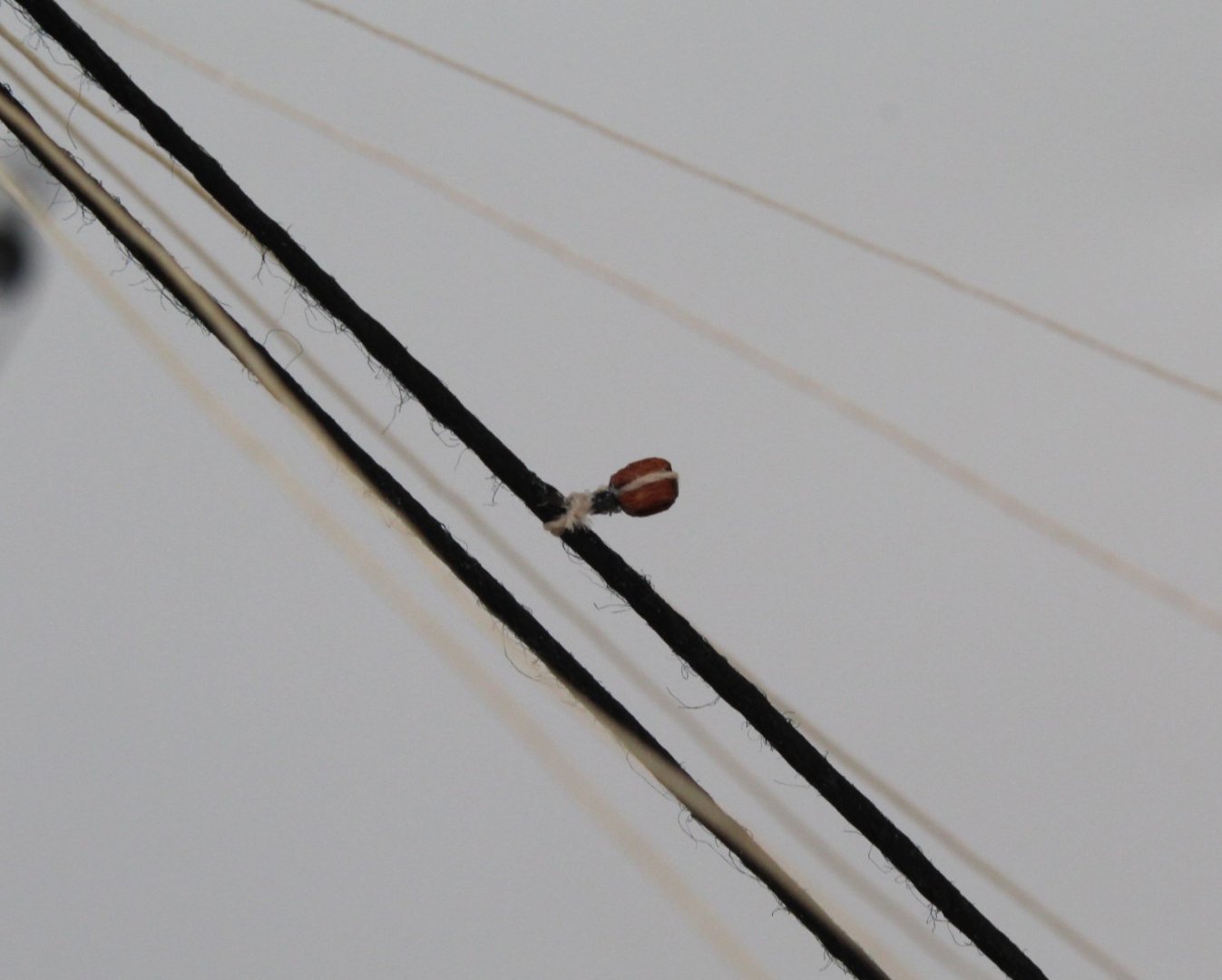
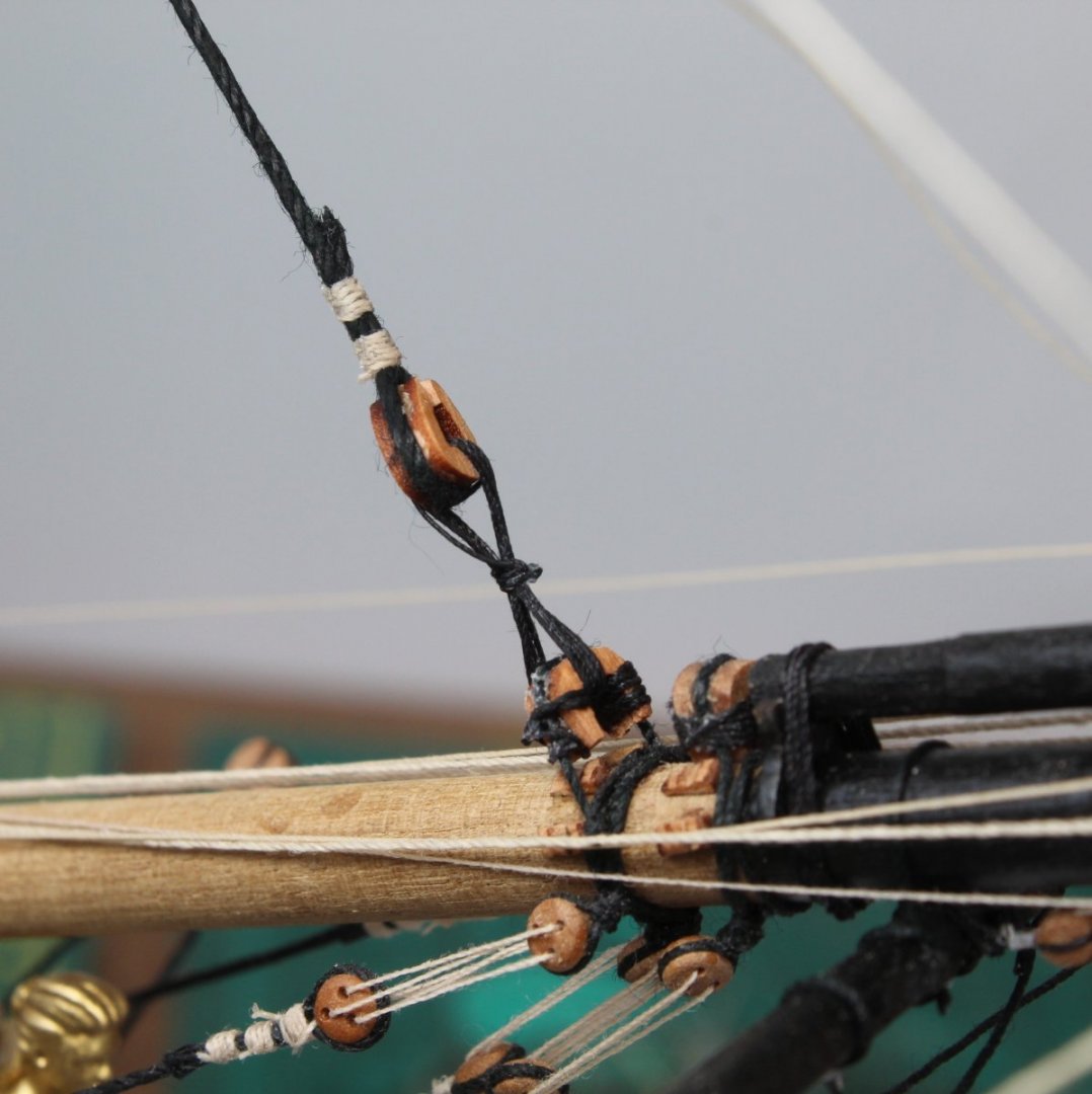
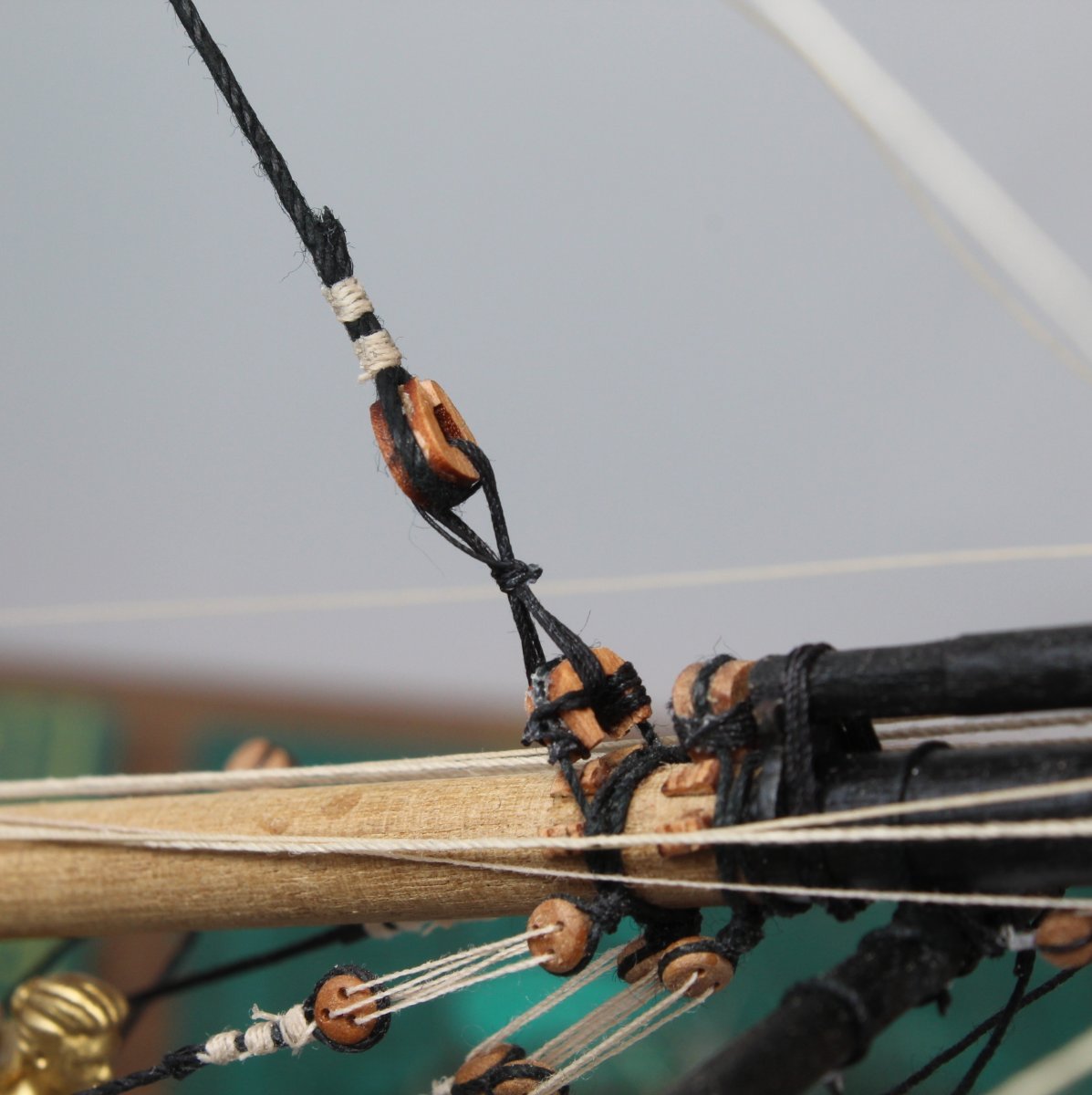
Finally I made a start on adding the fore and preventor stays. After making a thimble on one end of the fore stay thread I did a trial fit and decided that the mouse needed to be position approx 8cm from the thimble. I added knotted thread on the stay at the 8cm point which will stop the mouse moving any close to the mast. The following picture shows this arrangement. Tomorrow I plan to add a 6mm closed heart block to the other end of the fore stay so it can be linked with the open heart of the bowsprit. I will then repeat the process for the preventor stay. I have not used a open / closed heart arrangement before as my previous builds have used deadeyes. I am not sure, as yet, how I can ensure the stays are tensioned when the lanyards are added but I am sure I will figure it out.
-
One step forward and two steps back with the foreyard
After fitting the foreyard to the mast I noted I had incorrectly fitted 4mm double blocks for the jeers instead of using the 5mm double blocks shown on the plan sheets. Initially I thought I could get away with it as I was able to fed some 0.25mm thread through the 4mm double block holes when I tried on a spare block, noting I did find it necessary to run a micro drill through the block holes to slightly enlarge them.
However when I then tried to rig the actual jeers in situ it proved much more difficult and I was not very happy with how the jeer rigging was looking. Therefore I took the sensible decision (time will tell) to remove the foreyard from the mast and to replace the 4mm double jeer blocks with 5mm double blocks.
Thankfully the foreyard was easy to remove from the mast once I cut and removed the truss pendant thread. I was then able to remove the 4mm double blocks from the foreyard without any problems.
- Oldsalt1950, mtaylor and Dave_E
-
3
-
48 minutes ago, Oldsalt1950 said:
Very effective work around, and one would have to really look and know what the rigging is supposed to look like.
It looks good to me so I am happy. When looking at the jeer rigging I have realised I made an error when rigging the foreyard as I used 4mm double blocks instead of 5mm double blocks shown on the plans. It is not practical for me to change them as I would have to remove the yard which I do not wish to do. I have checked that the required 0.25mm natural thread can be fed through the 4mm double block holes so all is good to go. I will have to add the stays to the mast before the jeers are rigged before I hook the upper jeer blooks over the cleats on the mast. The stays can then be moved out of the way whilst I rig the jeers then the stays are then rigged to the bowsprit open heart blocks.
- Oldsalt1950, Dave_E and mtaylor
-
3
-
Foreyard Secured to Foremast
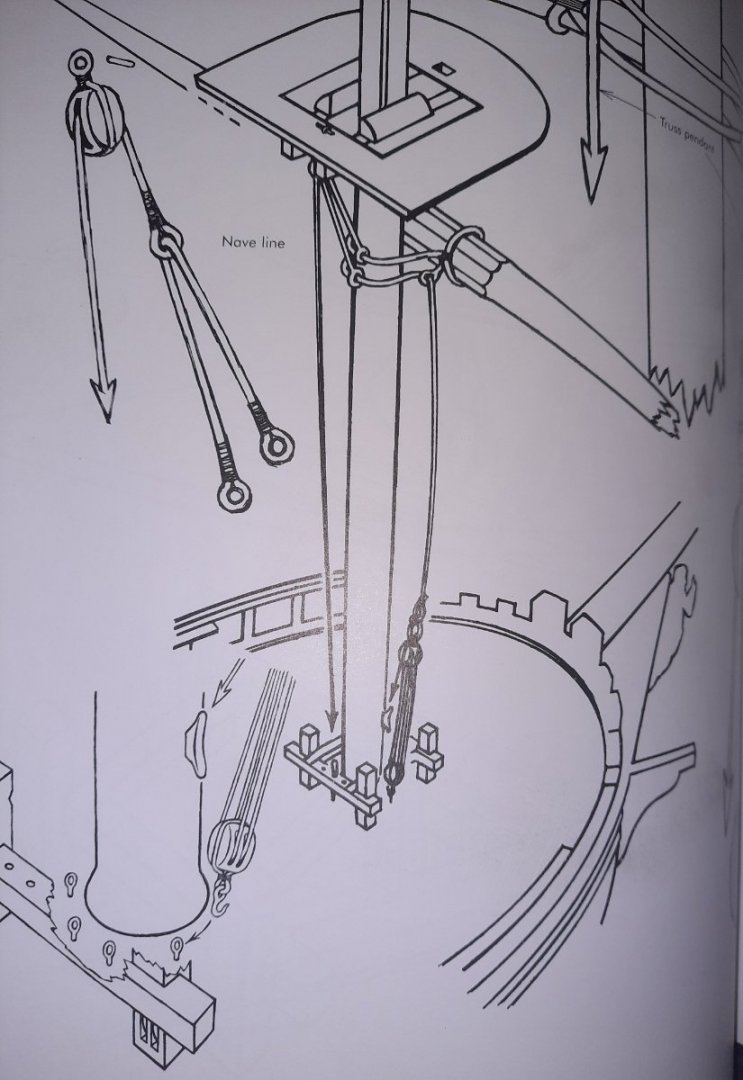
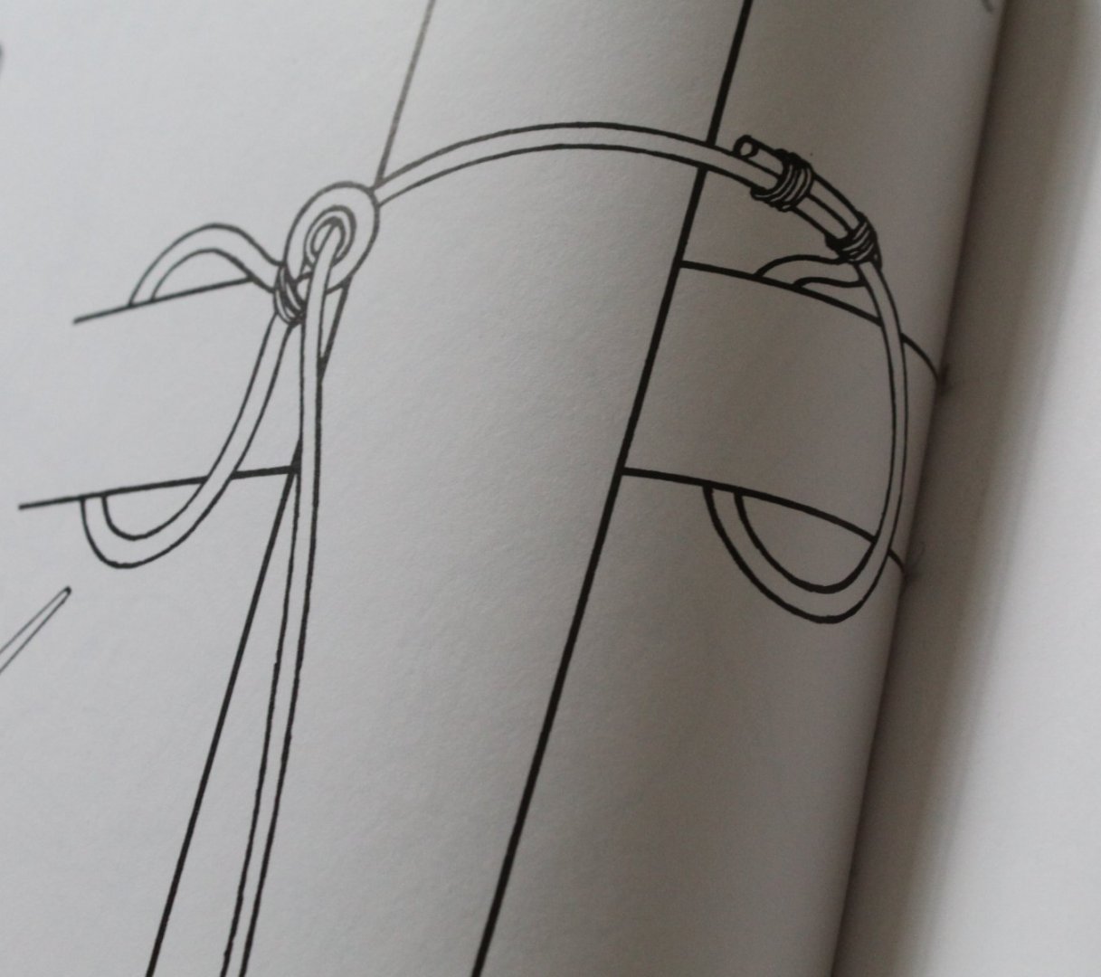
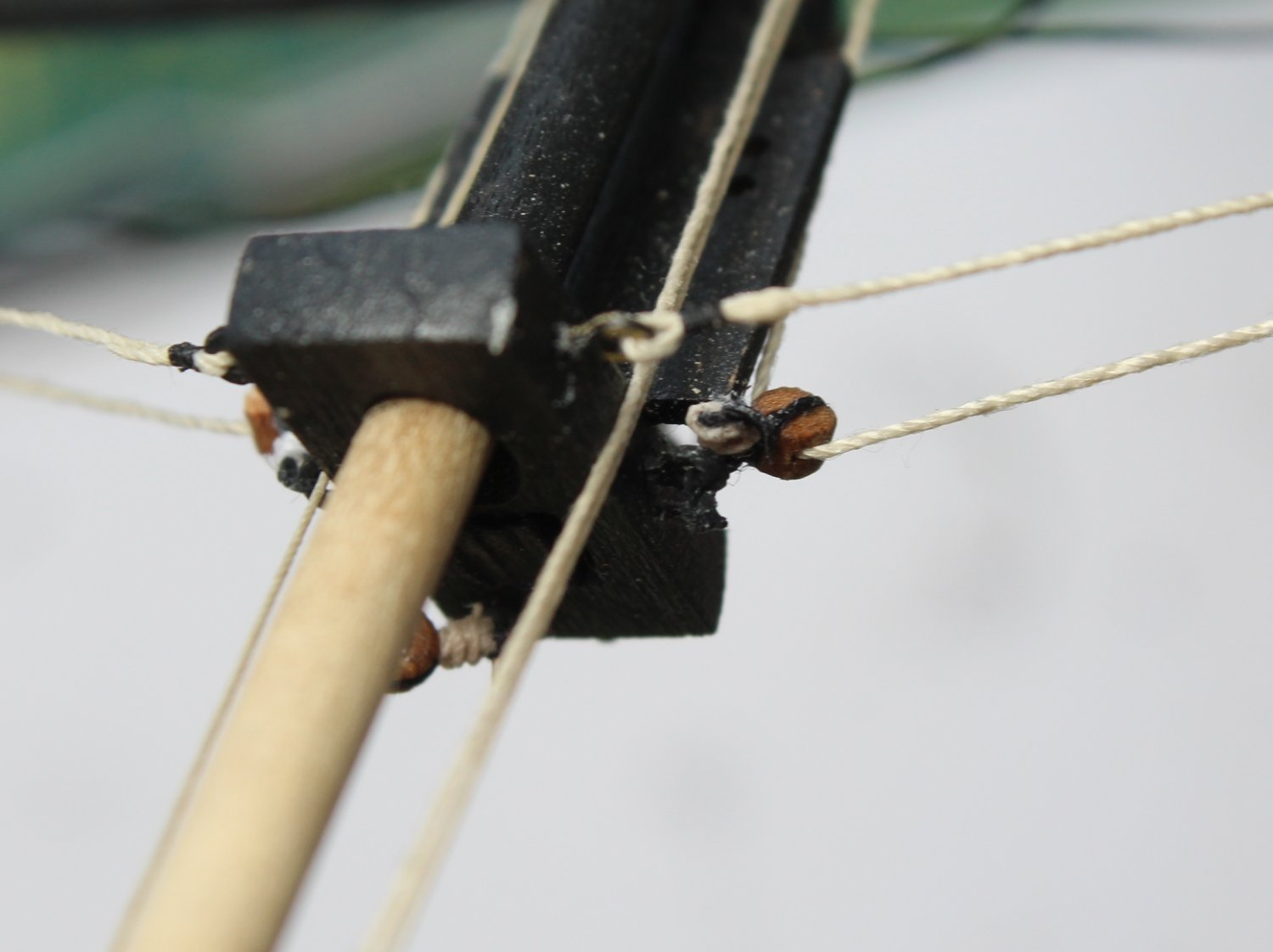
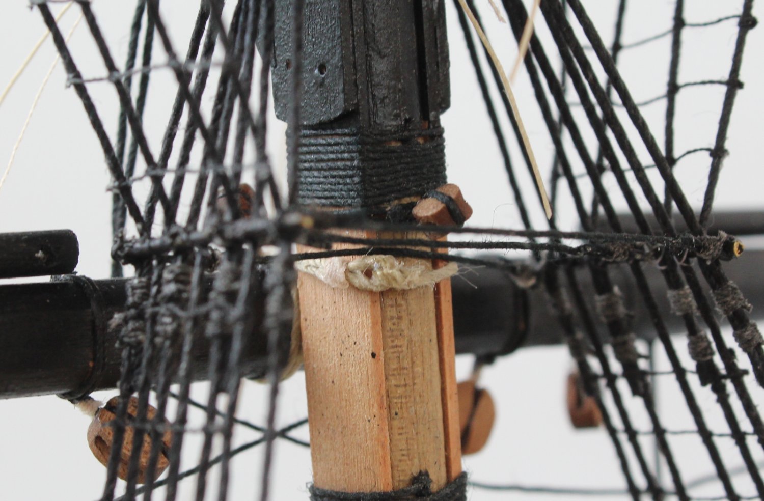
I had been debating the best method to secure the foreyard to the foremast over the last couple of days. After some research and advice from James H and MSW members I opted for a slightly modified version of the method detail in Lennarth's Petersson's book. See the picture below for Lennarth's method.

Lennarth's method seemed easy to do and it was similar to the method shown in Lee's book on Masting and Rigging (page 67). I did not think it was necessary to take the free end down to the deck for belaying (as shown in both reference books) and I agreed with Glenn (USA) that the free end of the pendant should be tied off at the mast. James H also confirmed he secured the yard to mast without the need to take a line down to the deck. I also thought the jeers, halliards and lifts would keep the yard firmly in play once they were rigged.
Using a simple clove hitch knot the truss pendants were added to the yard prior to fixing to the mast. The starboard side provided the free end and the port side provided the thimble which the free end would need to pass through before it was tied off. I had already added a pin to the yard and this was used to locate the yard on mast, with a touch a ca gel on the pin and a touch a wood glue on the yard, either side of the pin. The next picture shows the yard in place and, as can be seen, I positioned the clove hitch knots used to secure the truss pendants on top of the yard.

With the yard in place I was then able to feed the free end through the thimble and tied it off, as can be seen in the next couple of pictures.
Finally I have added a couple of pictures of the completed yard in place, I quite like the view shown in the first picture
Before moving on to adding the fore and fore preventer stays I think it may be an idea to rig the foreyard jeers and halliards for ease of access. I can also complete the partially rigged spritsail top yard braces. Once the fore and fore preventer stays have been added I can then complete the partially rigged spritsail yard braces which need to be tied off on the fore stay above the mouse.
- Oldsalt1950, BenD, scrubbyj427 and 8 others
-
11
-
-
1 hour ago, DocRob said:
Thank you very much Glenn, for explaining your methods of rigging ratlines and others. This will be a great help for my very first rigging on my Duchess of Kingston, same scale, same knots. I hope, I will learn from your experiences and don't ruin my nerves and yours along, when I bombard you with questions.
Cheers Rob
Hi Rob
I'm no expert but I'm to share my methods and ideas so feel free to ask away.
-
1 hour ago, glbarlow said:
I think it’s ok to pin the yard to the mast with a cut off nail. That way you’re not fully dependent on rigging to keep it in place. It’s completely in visible once done and with rigging in place. Your second diagram down is my vote except I’d tie it off to the mast, I’ve never run that rope down to belay, seems unlikely there would be two ropes running down. There should be a yard lift that raised and lowered it to be added later. That said I’ll defer to our maritime experts that I’m sure will offer an opinion.
Thanks, so many options to consider. I think I will try Lennarth's method (2nd picture) as that looks the easiest method. I will tie off on mast.
-
-
31 minutes ago, Oldsalt1950 said:
Glenn, was looking at your dilemma. Lee's book on Masting and Rigging page 67 has your answer. You will make two lines with eyelets /thimbles in the end, loop the line around the yard on each side of the mast them take the free end and pass it through the eyelet/thimble on the opposite side. These lines then run down to a block with a hook and attach to an eye fastened to the deck near the base of the mast.
I don't have Lee's book. Lennarth's book has a similar picture
- Dave_E, BenD, chris watton and 2 others
-
5
-
Foremast Yard - How To Secure To The Foremast?
I have completed all the work on the foremast yard and it is ready to be secured to the foremast. This post is a request for help as I'm unsure how to go about this task. I have detailed on possible method which I think can work but I would really appreciate any ideas / help in this respective.
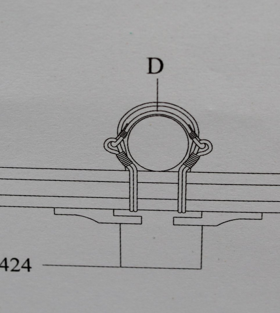
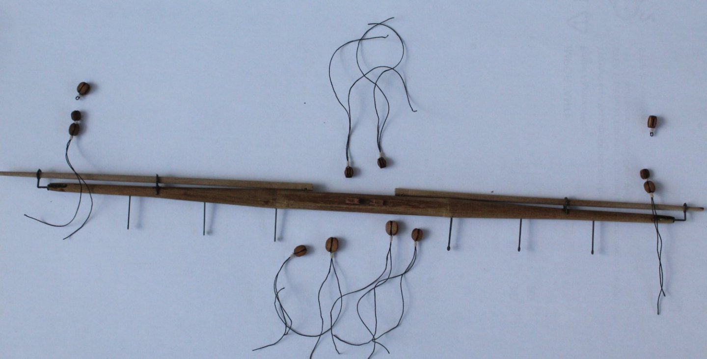
The photo below shows the plan sheet. It shows a small length of thread which is used to hold the yard to the foremast which is fed through and then seized to the some thread eyelets. There appears to be a second thread holding the yard to mast.
Next I looked at Lennarth Petersson's book, which showed something similar, but the linking thread is taken down to a belaying pin possibly via a block and tackle arrangement and maybe to a eyelet on the foremast channel.
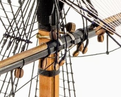
Finally I looked through Jim's excellent build log and found the following photo, but it was difficult to work out the method used.
Based on the above research I have come up with one possible method which I have trialled, as detailed below.
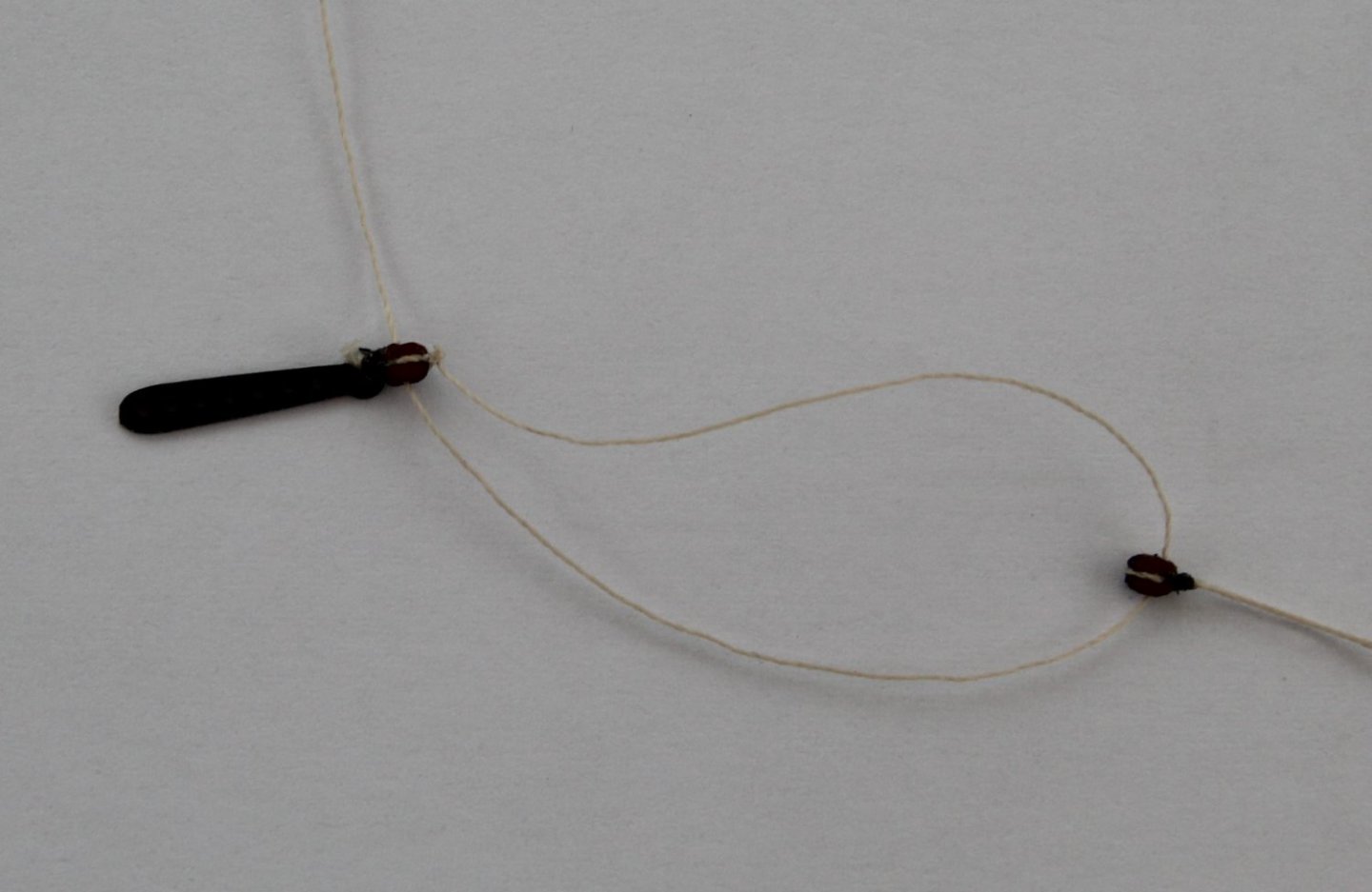
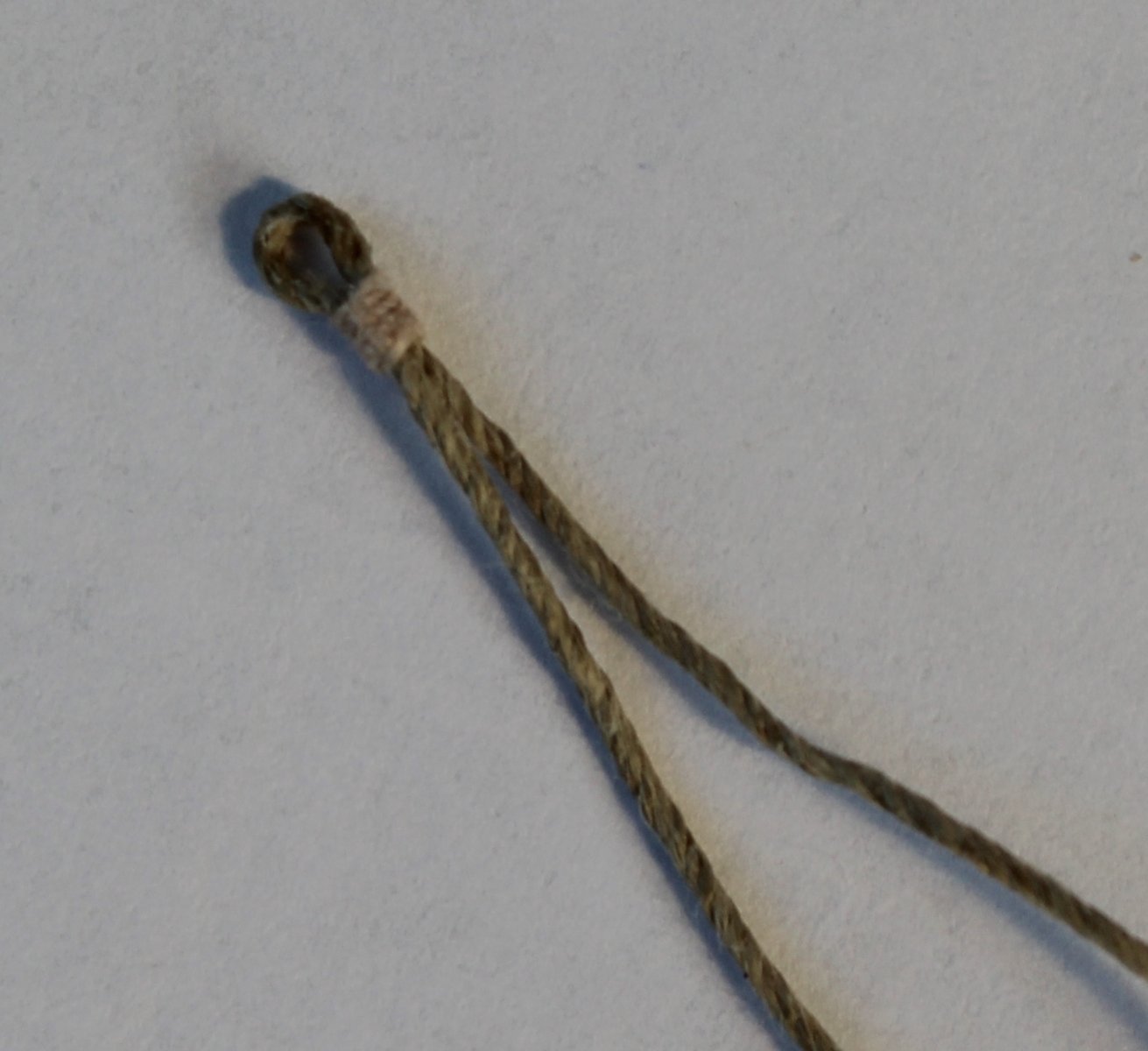
Stage 1 - Make a Eyelet
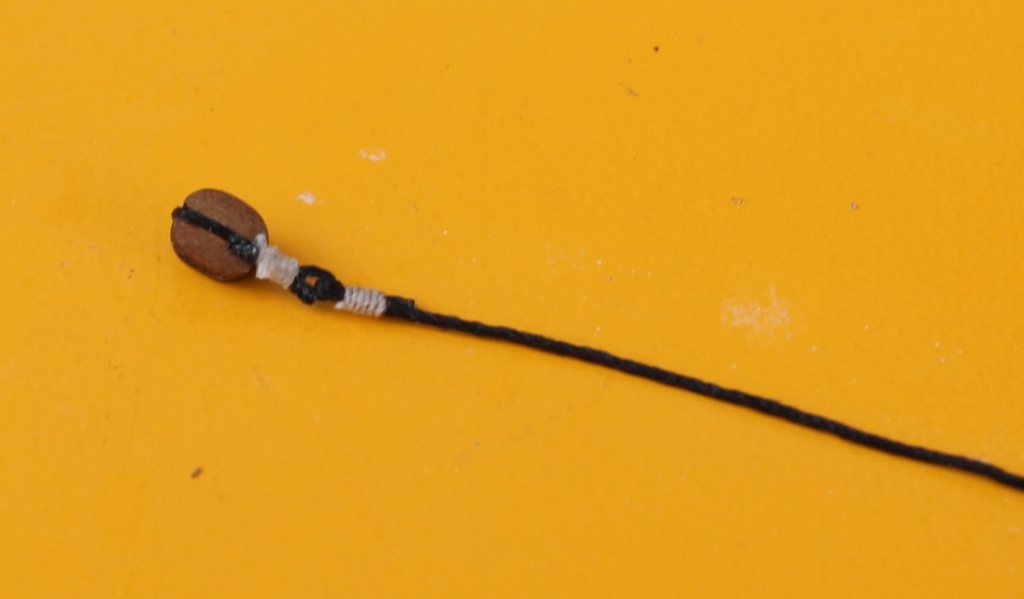
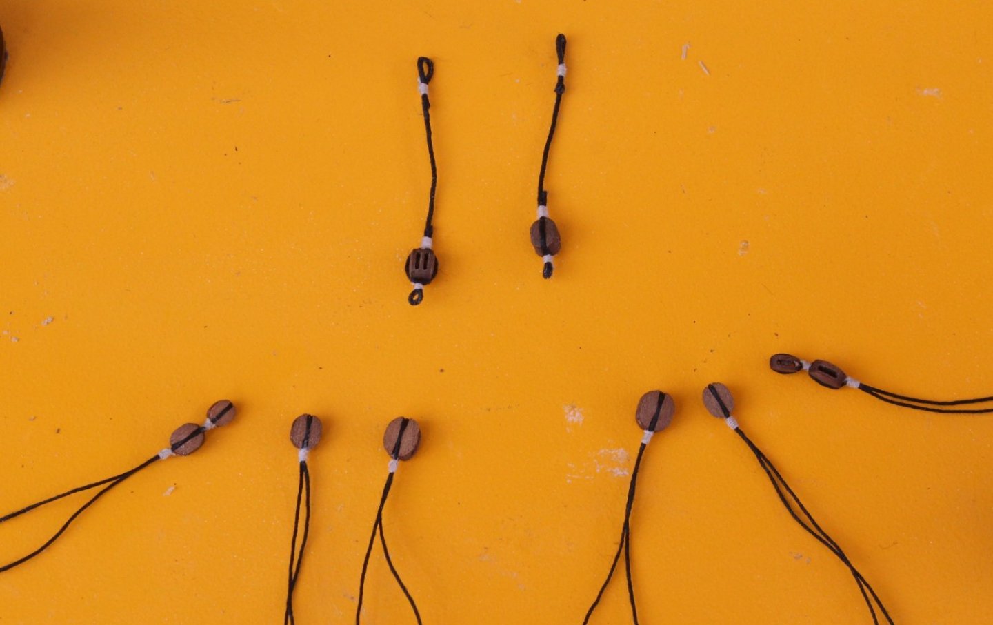
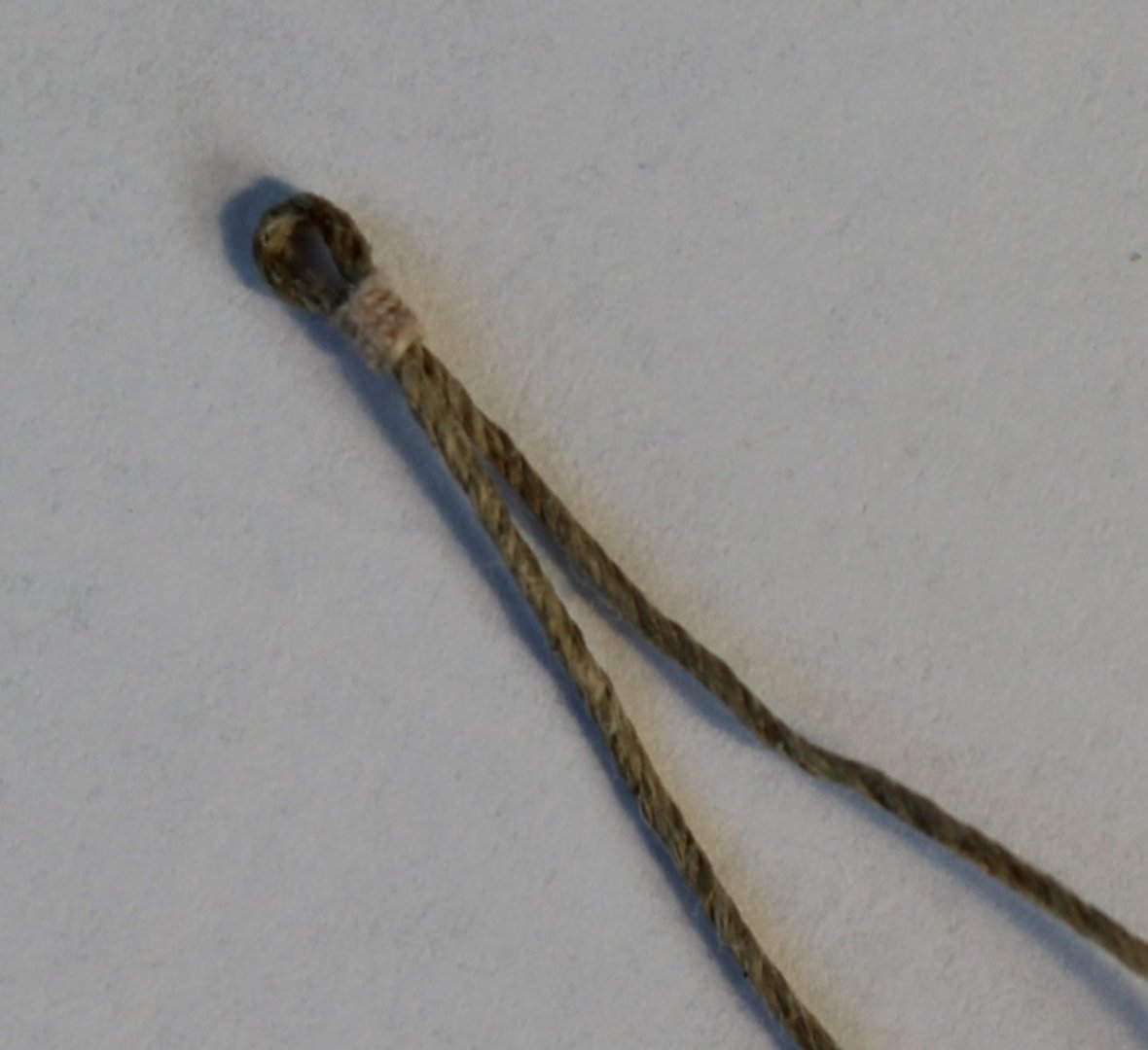
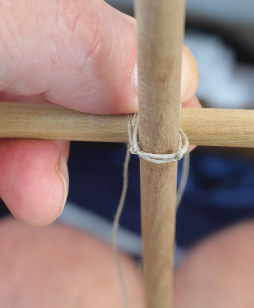
I took a length of 0.75mm natural thread and using some 0.1mm natural thread I added 5 seizing's coils to make an eyelet. It was important to ensure there were two equal lengths of the thread coming from the eyelet as can be seen in the photo below. This process was repeated to make a second eyelet again with two equal lengths of thread.
Stage 2 - Secure the eyelet thread to the yard
Taking one end of the first eyelet's thread I secured it to the yard using a simple clove hitch knot. To test the process I used a spare piece of 8mm dowel, noting the actual yard is octagonal with cleats to hold the thread in place.
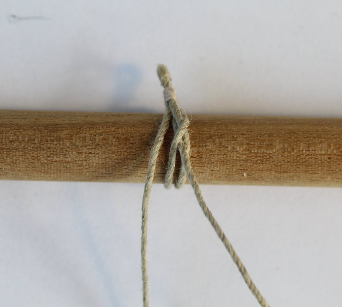
I have not applied any ca gel or trimmed the excess thread away on the test build once the knot was tightened as I intend to use these threads on the actual yards.
The second eyelet thread was also secured to the test yard, again using a clove hitch knot.
Stage 3 - Securing to the mast
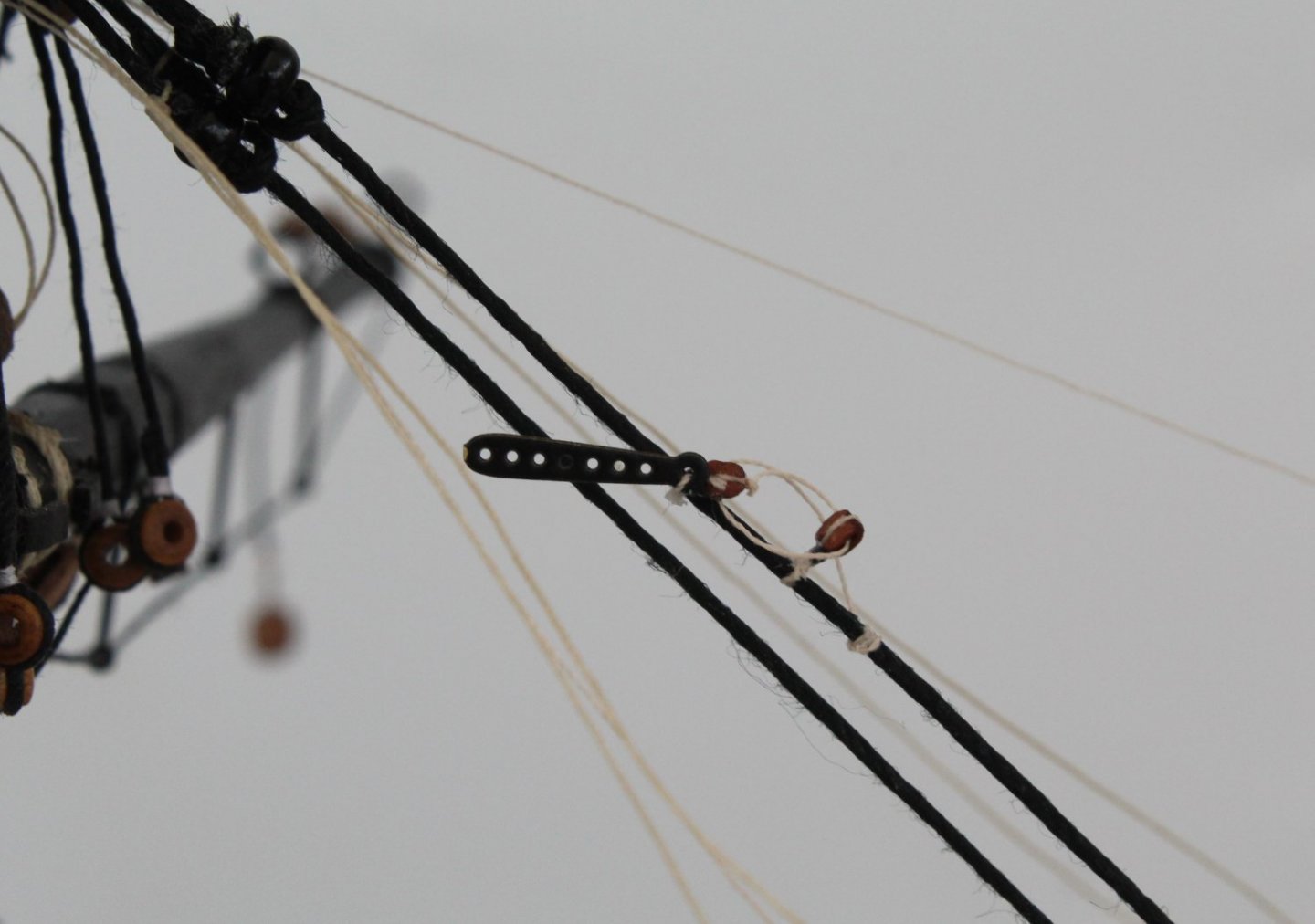
The next stage is to take one of the threaded eyelet ends and to pass it behind the yard before passing it through the opposite eyelet where it would then be seized.
The next step is to take the other eyelets thread end and to pass it behind the yard before threading through the opposite eyelet where it would then be seized.
I have not added the seizing in the photos below where the test yard has been secure to a test mast. The first photo shows the clove hitch knots and I am just holding the unseized ends in place so these threads can be used on the actual yards and mast. The clove hitch needs to be rotated by 180 degrees so it not visible.
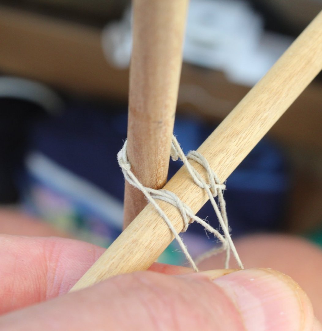
The next photo shows how the threads will hold the yard to the mast with the threads fed through their opposite eyelets.
Assuming there is room to add the seizing's on the actual model I think this method will work. I also need to check I can hold the thread in place under tension while the seizing is added.
As I said at the beginning of this post I am looking for help, suggestions on how to tackle this task.
-
Foremast Yard - Production
Yesterday I started work on the foremast yard. Firstly I made the 2 off stunsail booms. Each comprised a length of 3mm dowel which was tapered to 1.5mm along its length using my proxxon mini lathe. A 0.8mm hole was also drilled in each one, as shown on the plan sheet.
Next I moved on the main foremast yard. This was slightly more complicated and started life as a length of 8mm dowel. Leaving the middle section (66mm wide) at 8mm for the time being each end of the dowel was tapered down to 3.5mm on the mini lathe. During the tapering process I made sure the 2 x stunsail support brackets would fit. Once I was happy with the tapering the middle section was shaped (very badly) as an octogen and once that was complete the two cleats were glued in place. Next I added the stunsail end irons and hooks and completed the process by drilling the yard for the yard footrope stirrups.
Today I moved on the various blocks and spent a couple of hours seizing thread to the various blocks. A couple of blocks required eyelets and there were a couple of double block seizing required. With this task complete the next task will be to add them to the main yard and to rig the footrope stirrup's. Once that is done I can secure the stunsail booms in place and paint the completed yard assembly black.
The follow photo shows the current progress, the stunsail booms and footrope stirrup's are only dry fitted.
-
16 minutes ago, glbarlow said:
I run one color highlighter over every tenth row line on the card and a different color over the fifth row between those, helps to keep track. I learned that trick from someone here on the forum.
That is a good idea, I could do something similar when I print out the template. That said my pencil annotations X, 0, 1 and 2 works OK also.
-
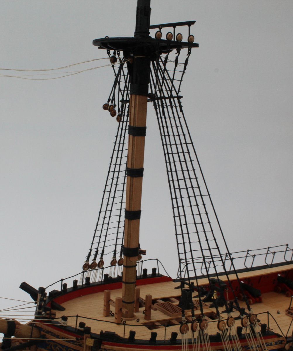
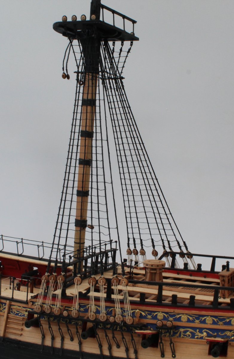
Lower Ratlines Completed
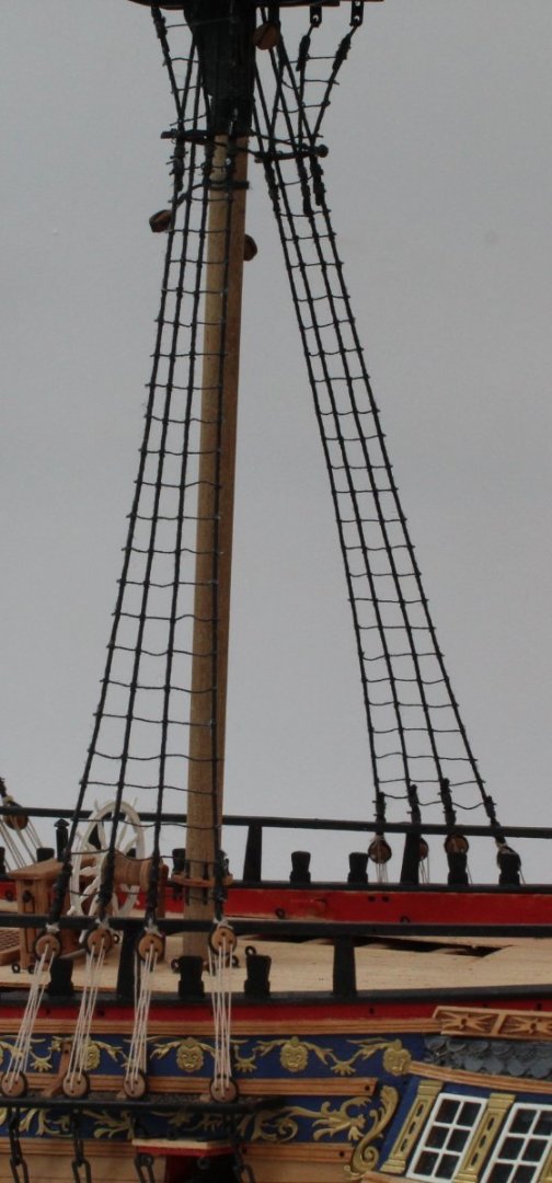
I had a really good day in the shipyard today and managed to complete the ratlines for the lower masts, approx. 1000 clove hitch knots tied. I am reasonably happy with the end result as they look much better than any of my previous builds.
I now need to manufacture the Fore Yard, Main Yard and Crossjack Yard and associated Stunsail Booms. Once complete they will be added to their respective masts before I can start work on adding the stays.


- DelF, PhillH, KARAVOKIRIS and 9 others
-
12
-


HMS Sphinx 1775 by Glenn-UK - FINISHED - Vanguard Models - 1:64 - V2 Kit by Glenn Shelton
in - Kit build logs for subjects built from 1751 - 1800
Posted
Foreyard - Completed
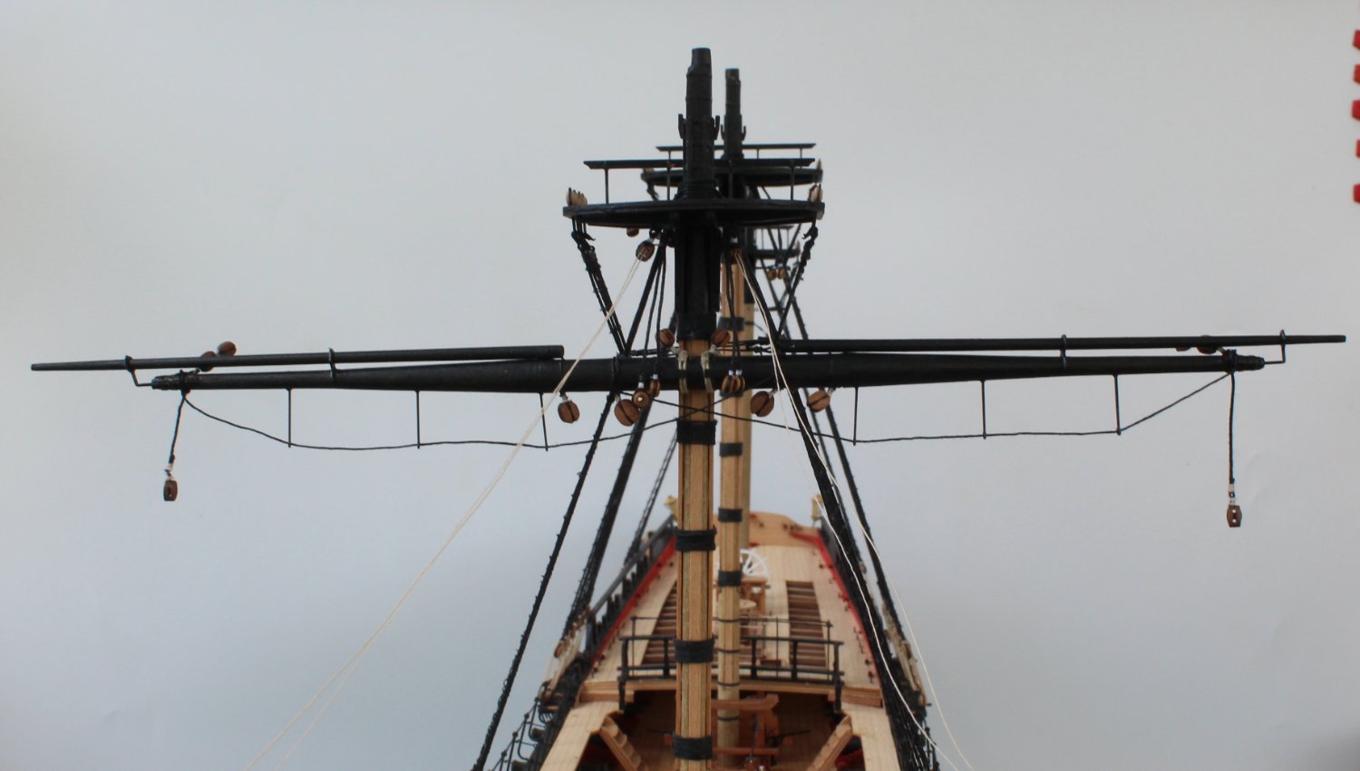
I have now completed the work on the foreyard and it has been secured to the foremast. I might try to remove the braces as I not totally happy with their position because they need to be aft facing when rigged but they are hanging down on the bow side of the yard at the moment. It may be OK when the braces are rigged, time will tell.
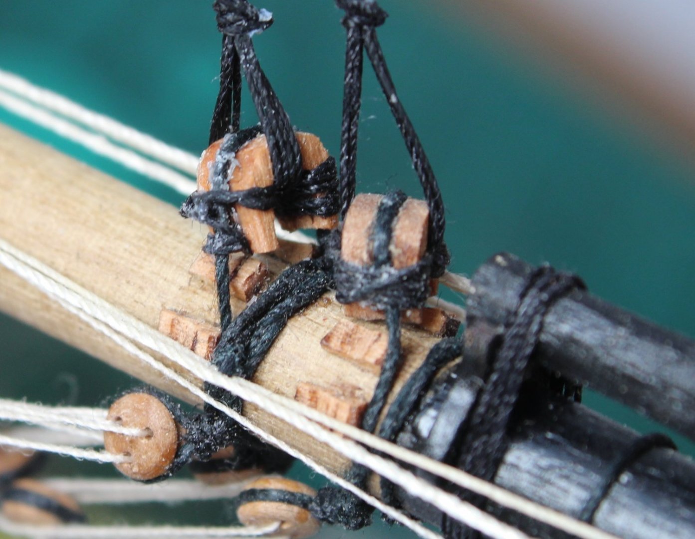
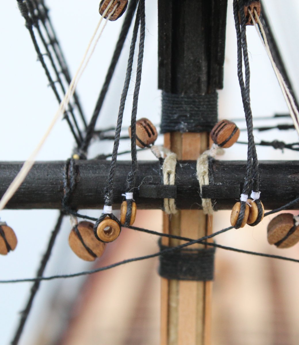
This is a close up of the jeers and truss pendants. The truss pendants have not been belayed as yet.
When looking at rigging plan sheet 3 it appeared to me that the belaying point was on the chain pump assembly as can be seen below.
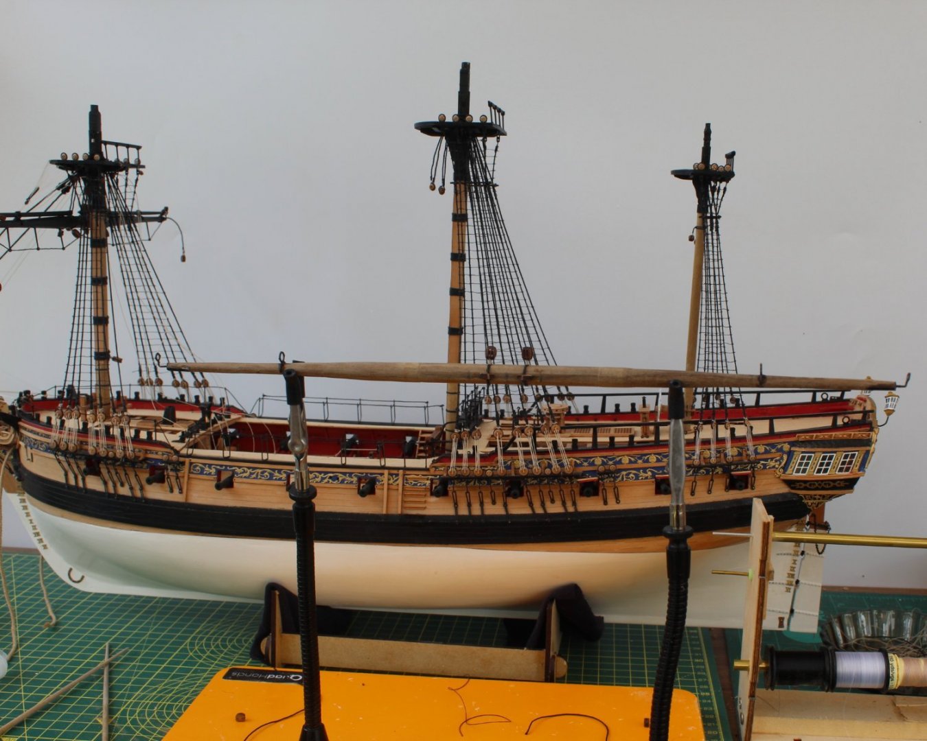
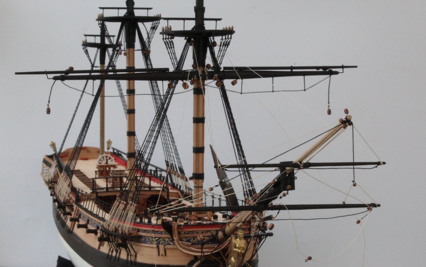
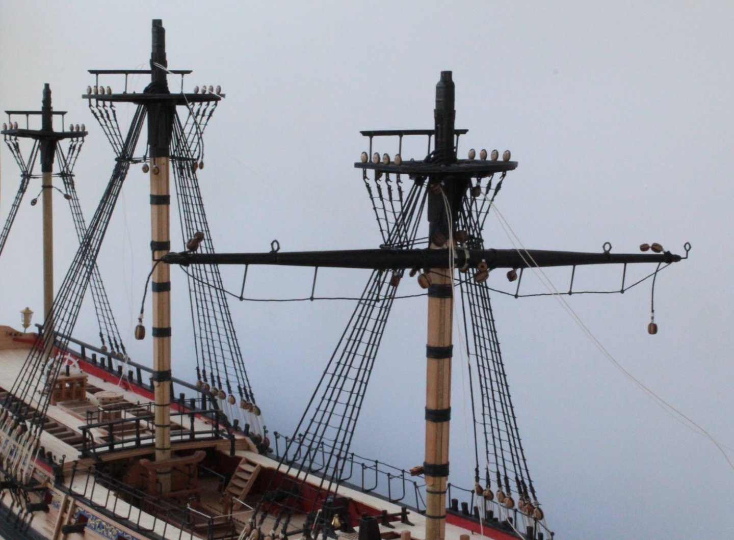
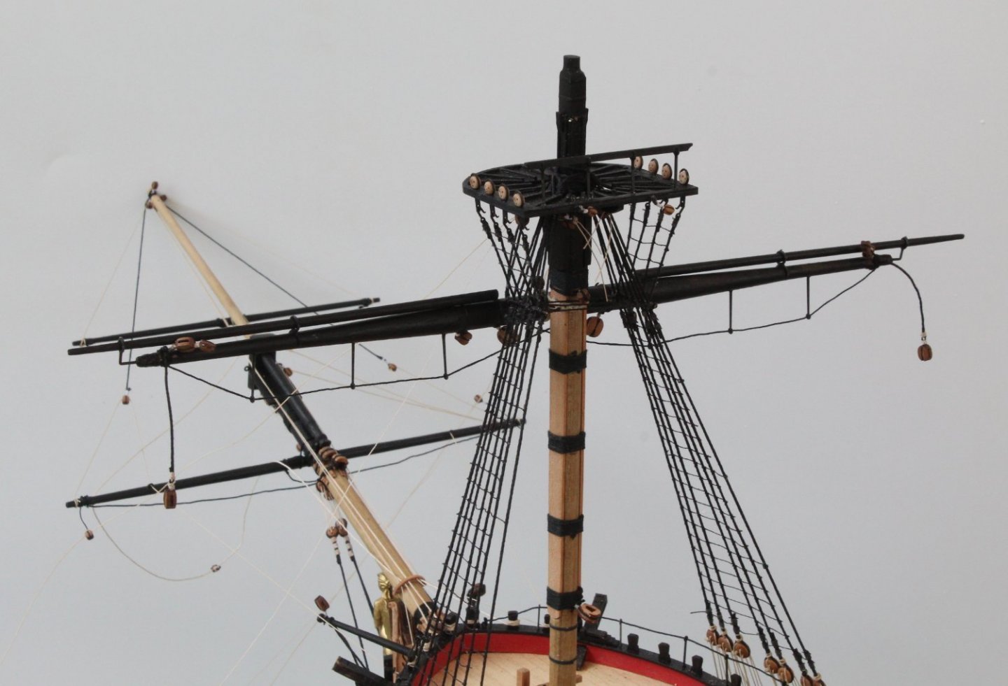
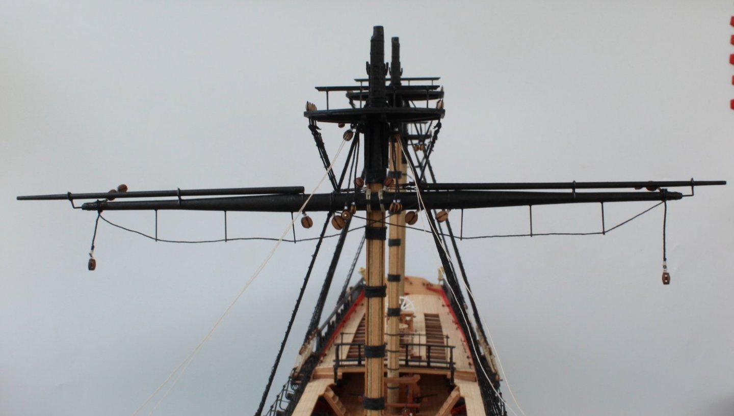
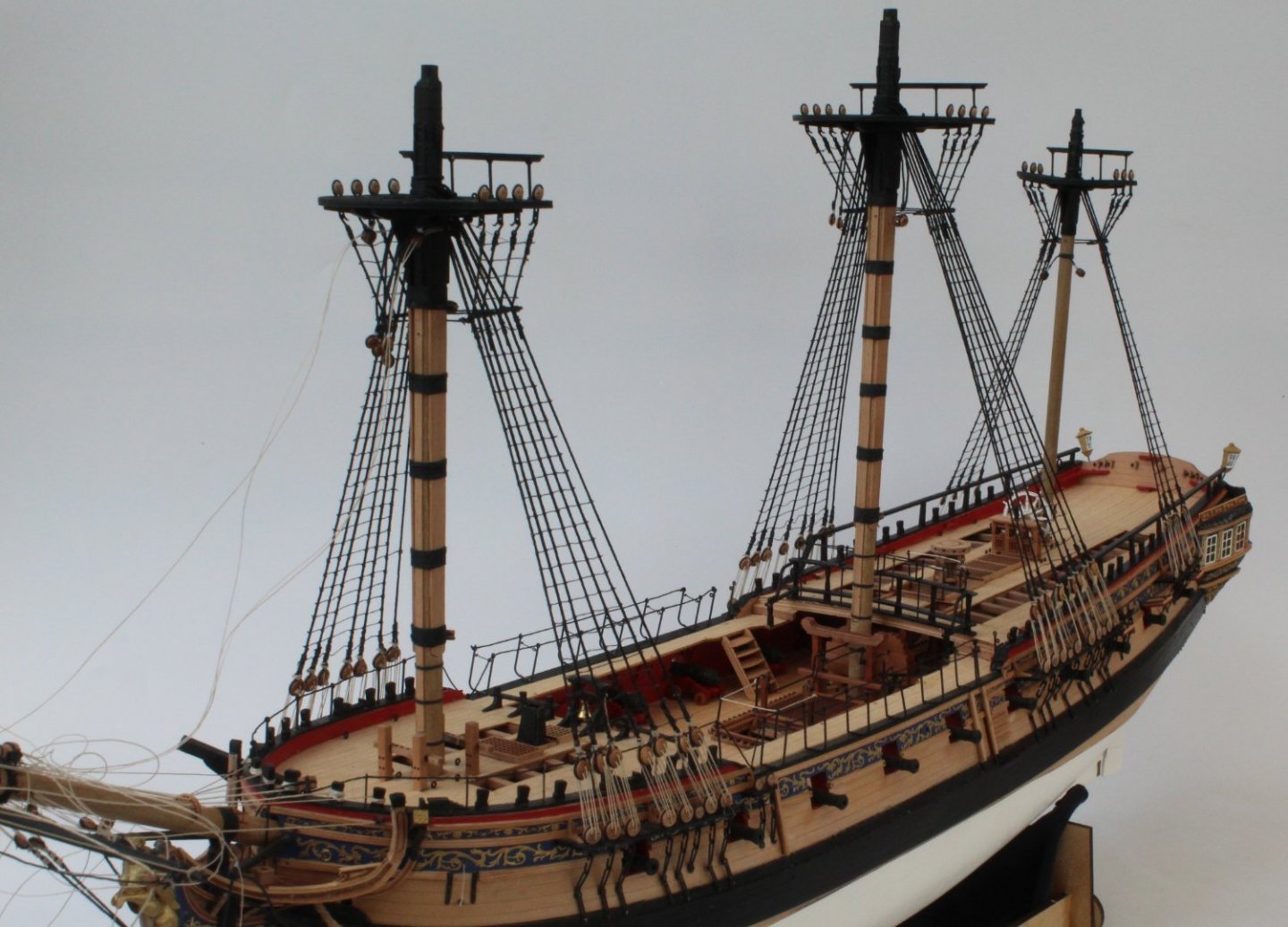
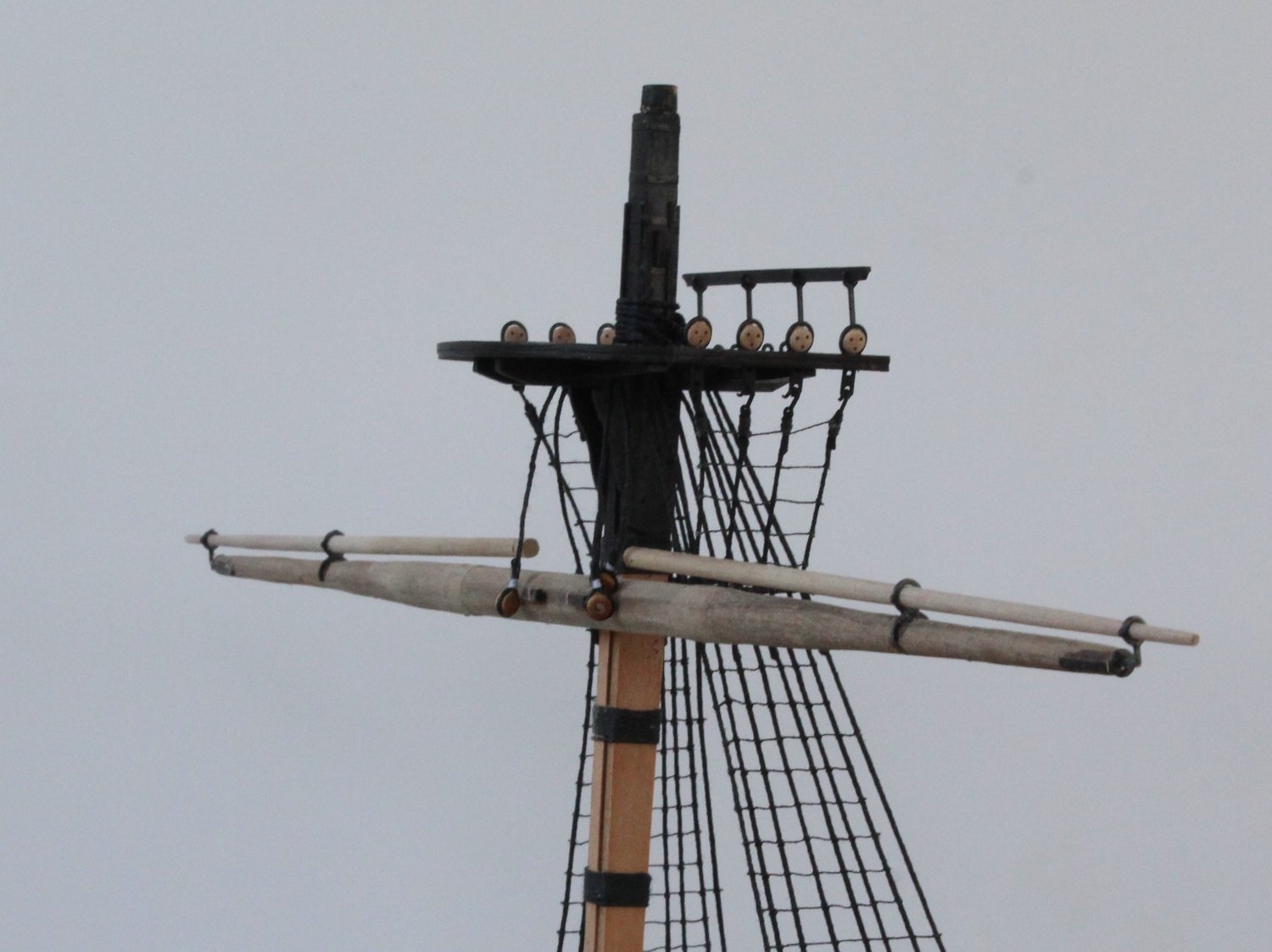
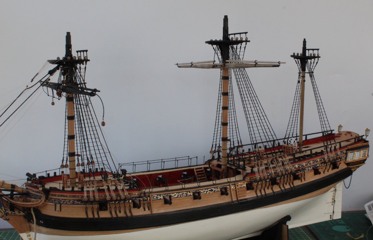
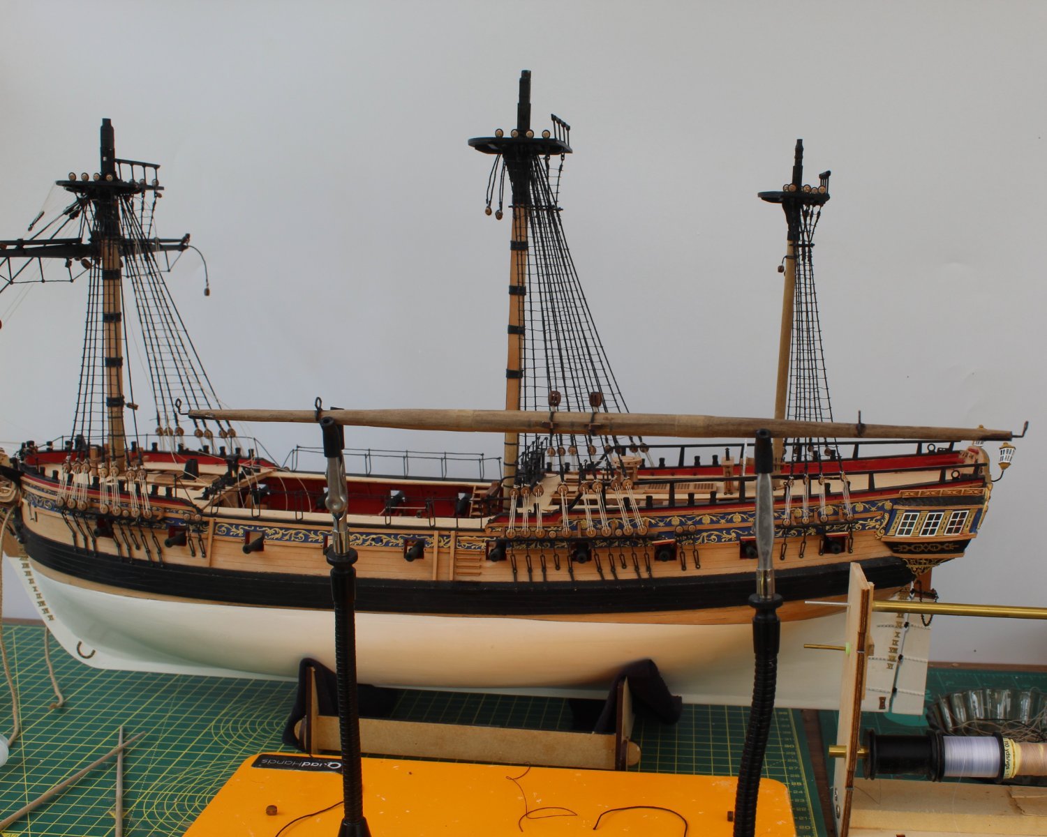
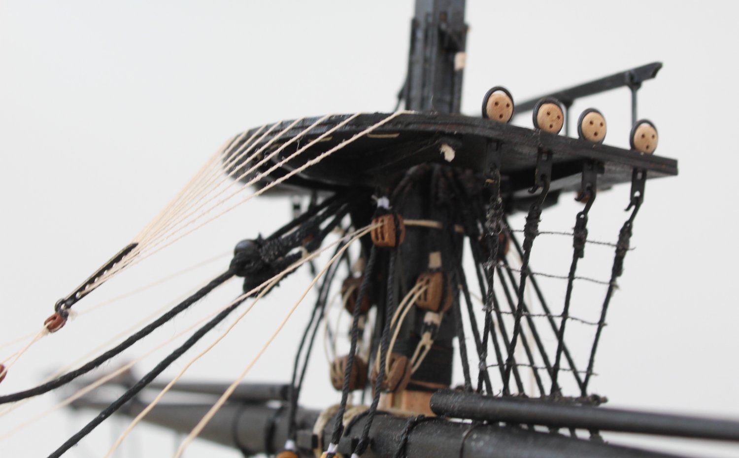
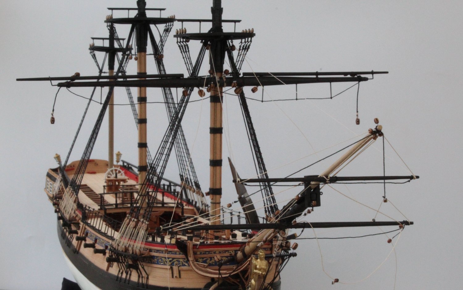
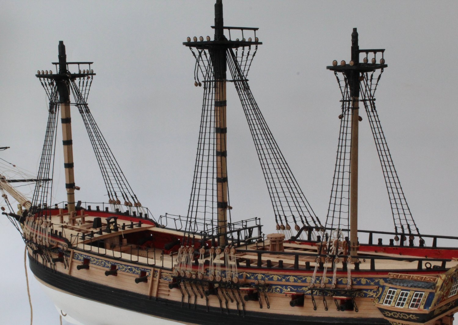
The next photo shows a nice view of the fore and main masts complete with the yards.
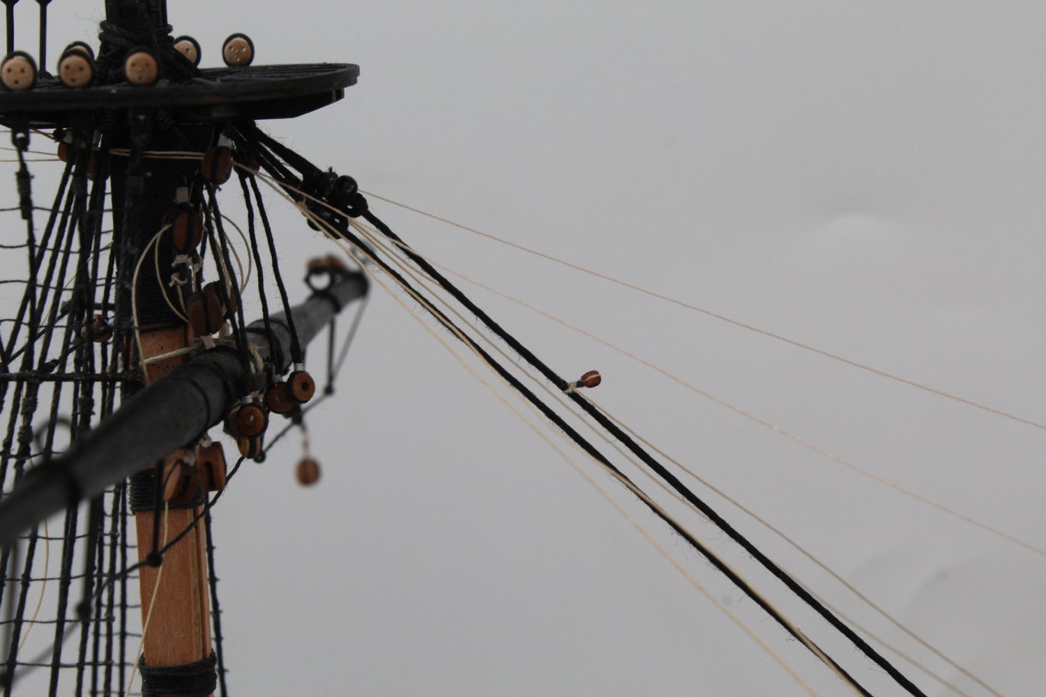
I have added the closed heart blocks to the main and preventor stays but I have not added the lanyards. I have used a couple of reverse action tweezers to show these stays in position.