archjofo
-
Posts
1,501 -
Joined
-
Last visited


-
 Thukydides reacted to a post in a topic:
La Créole 1827 by archjofo - Scale 1/48 - French corvette
Thukydides reacted to a post in a topic:
La Créole 1827 by archjofo - Scale 1/48 - French corvette
-
 Knocklouder reacted to a post in a topic:
La Créole 1827 by archjofo - Scale 1/48 - French corvette
Knocklouder reacted to a post in a topic:
La Créole 1827 by archjofo - Scale 1/48 - French corvette
-
dvm27 reacted to a post in a topic:
La Créole 1827 by archjofo - Scale 1/48 - French corvette
-
dvm27 reacted to a post in a topic:
La Créole 1827 by archjofo - Scale 1/48 - French corvette
-
rybakov reacted to a post in a topic:
La Créole 1827 by archjofo - Scale 1/48 - French corvette
-
Tigersteve reacted to a post in a topic:
La Créole 1827 by archjofo - Scale 1/48 - French corvette
-
tlevine reacted to a post in a topic:
La Créole 1827 by archjofo - Scale 1/48 - French corvette
-
davyboy reacted to a post in a topic:
La Créole 1827 by archjofo - Scale 1/48 - French corvette
-
Dr PR reacted to a post in a topic:
La Créole 1827 by archjofo - Scale 1/48 - French corvette
-
pjofc4 reacted to a post in a topic:
La Créole 1827 by archjofo - Scale 1/48 - French corvette
-
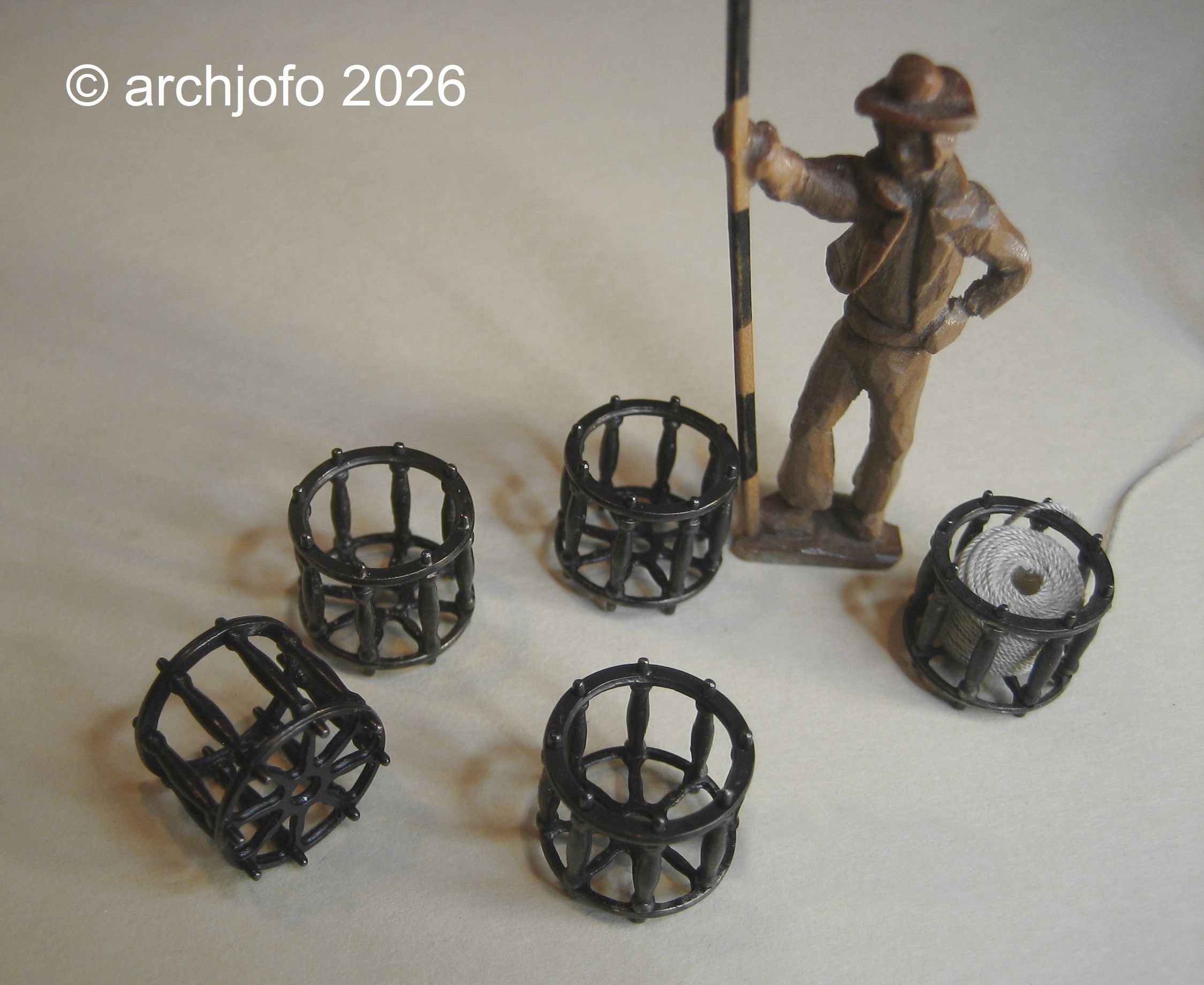
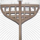
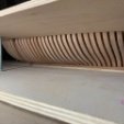
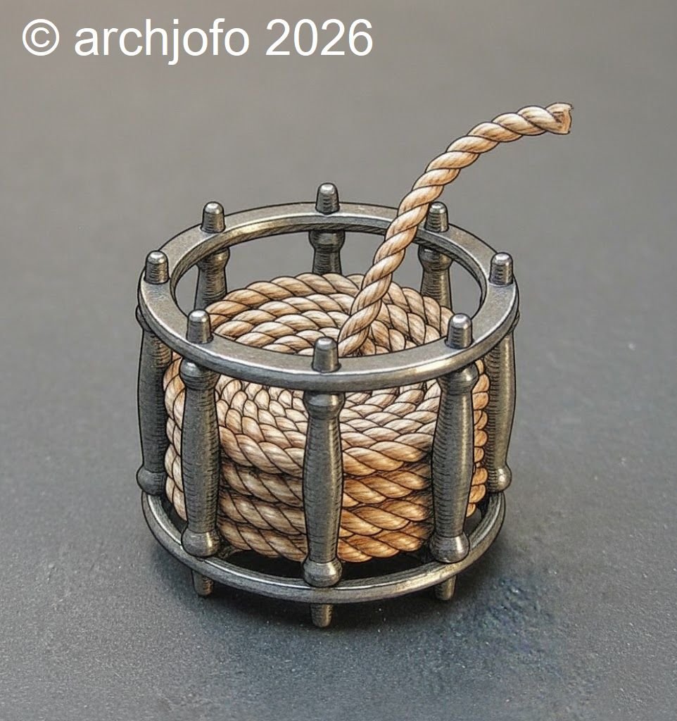
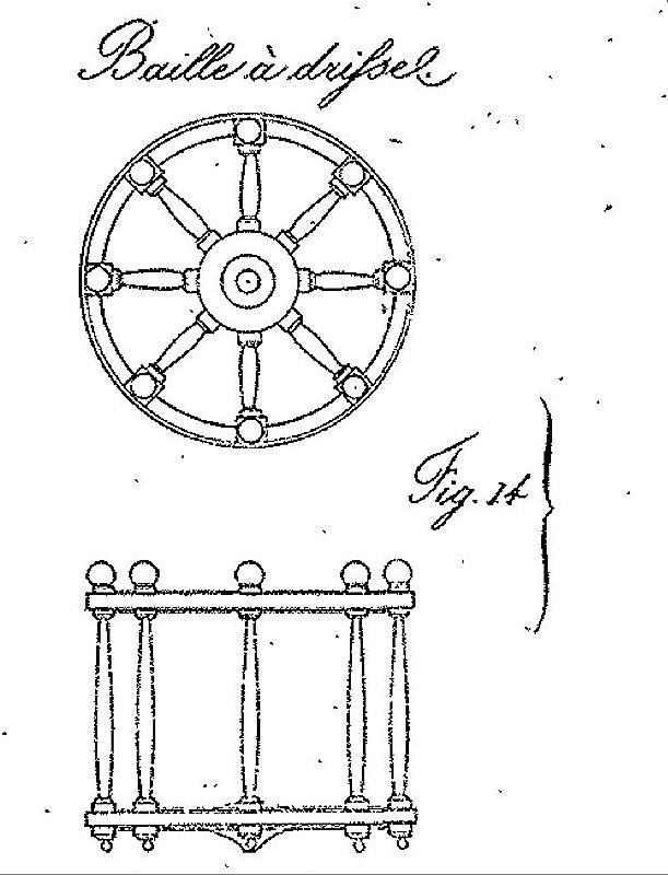
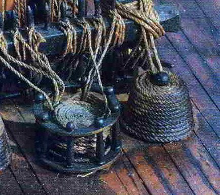
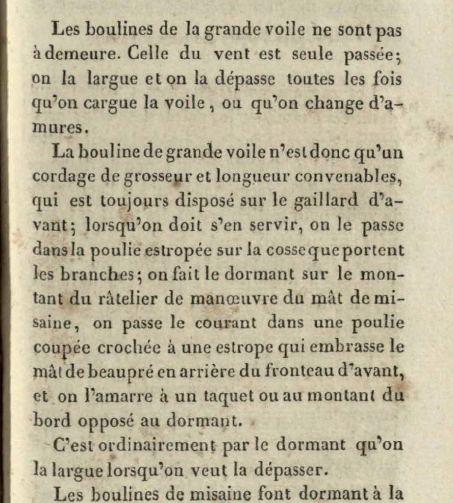
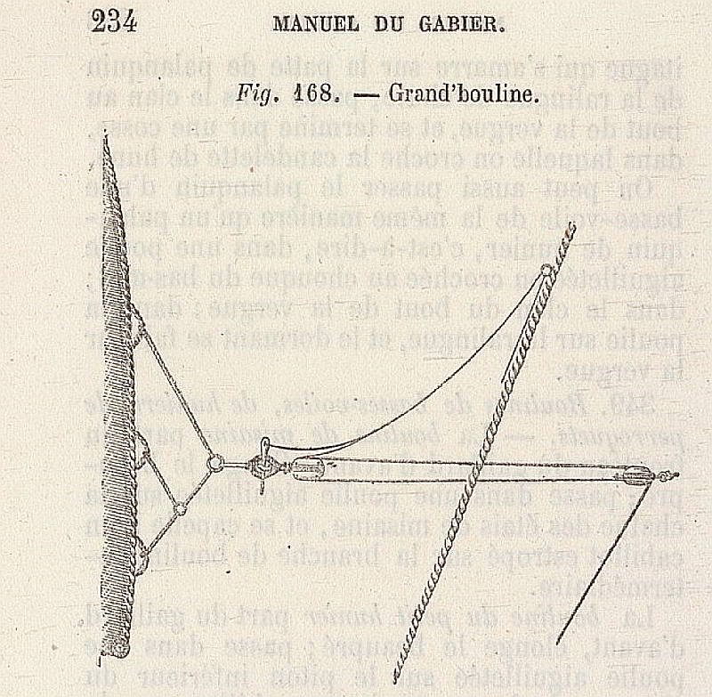
 @jdbondy Thank you so much for your kind comment, and thank you to everyone else for the likes. Rope tubs for halyards and sheets - Baille à drisse I am currently securing the running rigging of the foreyard at the appropriate points. In this context, the loose ends of the foreyard sheets also need to be stowed. On French ships of the first half of the 19th century, this was done in so-called bailles à drisse – roughly translated as rope tubs, in which the lines lay neatly coiled and ready. In Dr. Eduard Bobrik's "Allgemeinen nautischen Wörterbuch" of 1858, they are mentioned as follows: Contemporary handbooks clearly describe the function of these containers. In the Manuel du Gabier (1827), it states: "Les drisses doivent être lovées proprement et déposées dans la baille, afin qu’elle puissent filer sans embarras." (“The lines must be neatly coiled and placed in the container so they can run without snagging.”) The Manuel du Matelot (1811) adds: “ Les cordages de manœuvre sont rangés dans des bailles pour les préserver de l’humidité et du désordre. ” (“The maneuvering lines are stored in containers to protect them from moisture and disorder.”) This clearly defines their function: order, dryness, and free-running lines without dragging on the deck or becoming tangled. The Manuel du gréement – frégate de 44 canons (1828) describes, by way of example, how these containers were moved as needed when a free run had to be ensured when a rope was being let out. This prevented loops from forming or the rope from snagging on the deck. This source proves that the baille à drisse was an active piece of equipment, its position adjusted depending on the maneuver situation—not merely a static storage location. The shape of these containers is not described in detail in the texts, but the Atlas du Génie Maritime and several shipyard models in the Musée de la Marine (e.g., La Belle Poule) clearly show cylindrical, open baskets with vertical struts. Source: Atlas du Génie Maritime Source: Musée national de la Marine Some time ago, I made such baille baskets for my 1:48 scale La Créole and presented them in the construction report. For the construction of my baskets, I used a corresponding drawing from the Atlas du Génie Maritime as a guide. As with the historical shipyard model, I will install a total of five: two at the foremast, two at the mainmast, and one at the mizzenmast. In the French Navy of the early 19th century, bailles à drisses were mobile wooden containers used for both the organized storage and dry keeping of running rope, particularly halyards and sheets. 1. Safe, dry storage of rope Between maneuvers, the lines were neatly coiled and stored in these containers. This protected them from: • Dampness on the deck • Dirt • Tangles • Damage from chafing The containers were therefore located in close proximity to the respective rigging, usually at the base of the mast or where the lines led onto the deck. 2. Organized handling during maneuvers During sailing maneuvers, the containers served to neatly gather the running or hauled-in rope. They prevented: • lines from dragging across the deck • lines from wrapping around fittings or blocks • loops from forming • crew members from being hindered in their work 3. Situational Repositioning During Maneuvers The Manuel du gréement (1828) describes a specific case on page 234 in which the officer has the containers briefly moved aside to prevent loops from forming and snagging when a halyard runs out. This example demonstrates: • The containers are not permanently mounted • They are positioned according to the maneuver situation • They are an active tool, not just a storage location The described case is a practical example, but it confirms the fundamental function of these containers. The initial temporary placement of a rope tub on the foremast shows the direction things are headed. The design with small feet lifts the container slightly off the deck, thus reflecting the practical logic also mentioned in the Manuel du gréement of 1828. The final placement of all five rope tubs will only take place after the rigging of the running rigging is complete and the belaying points have been cleaned up. These will later receive their coils, so the overall appearance will only be complete once the final setup is finished. Until next time…
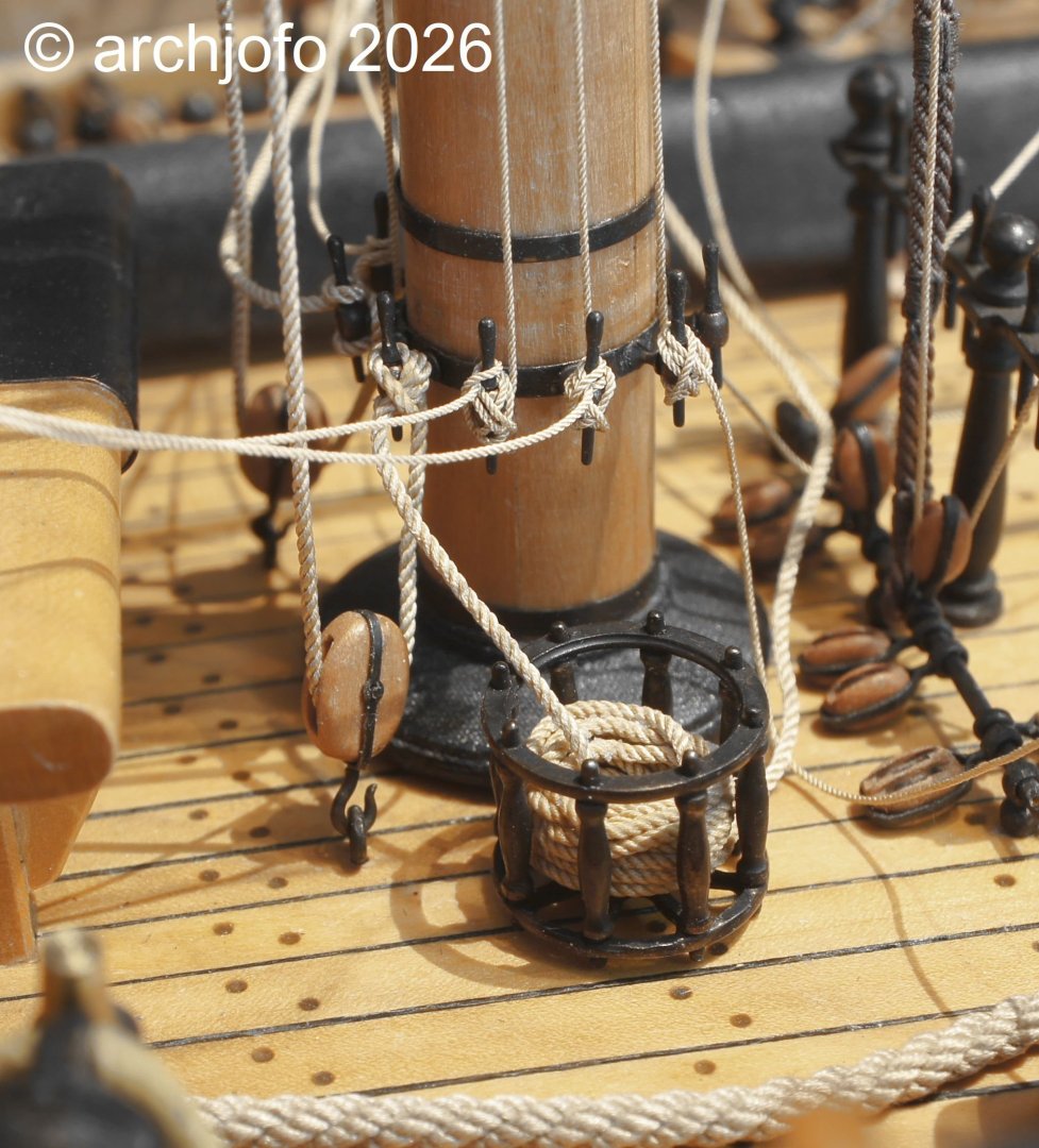


-
archjofo reacted to a post in a topic:
La Créole 1827 by archjofo - Scale 1/48 - French corvette
-
archjofo reacted to a post in a topic:
Columbia 1835 by Glen McGuire - 1/400 - BOTTLE - Steam Packet
-
archjofo reacted to a post in a topic:
Columbia 1835 by Glen McGuire - 1/400 - BOTTLE - Steam Packet
-
archjofo reacted to a post in a topic:
LA CREOLE/ LA GUADELOUPE by matiz - 1:48 - by Tiziano Mainardi from Boudriot plans
-
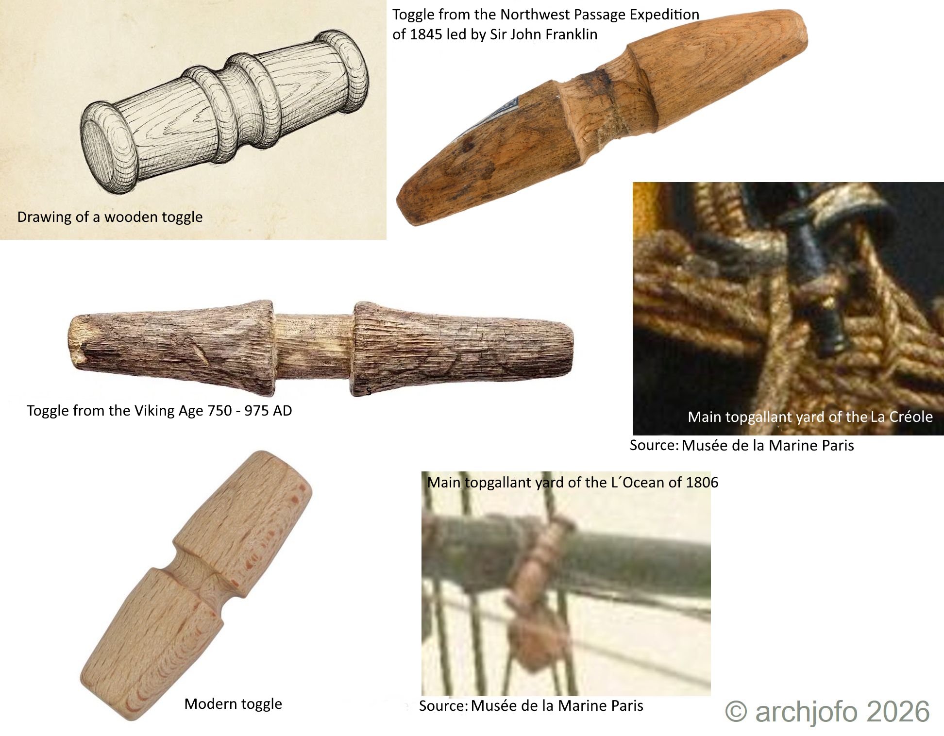
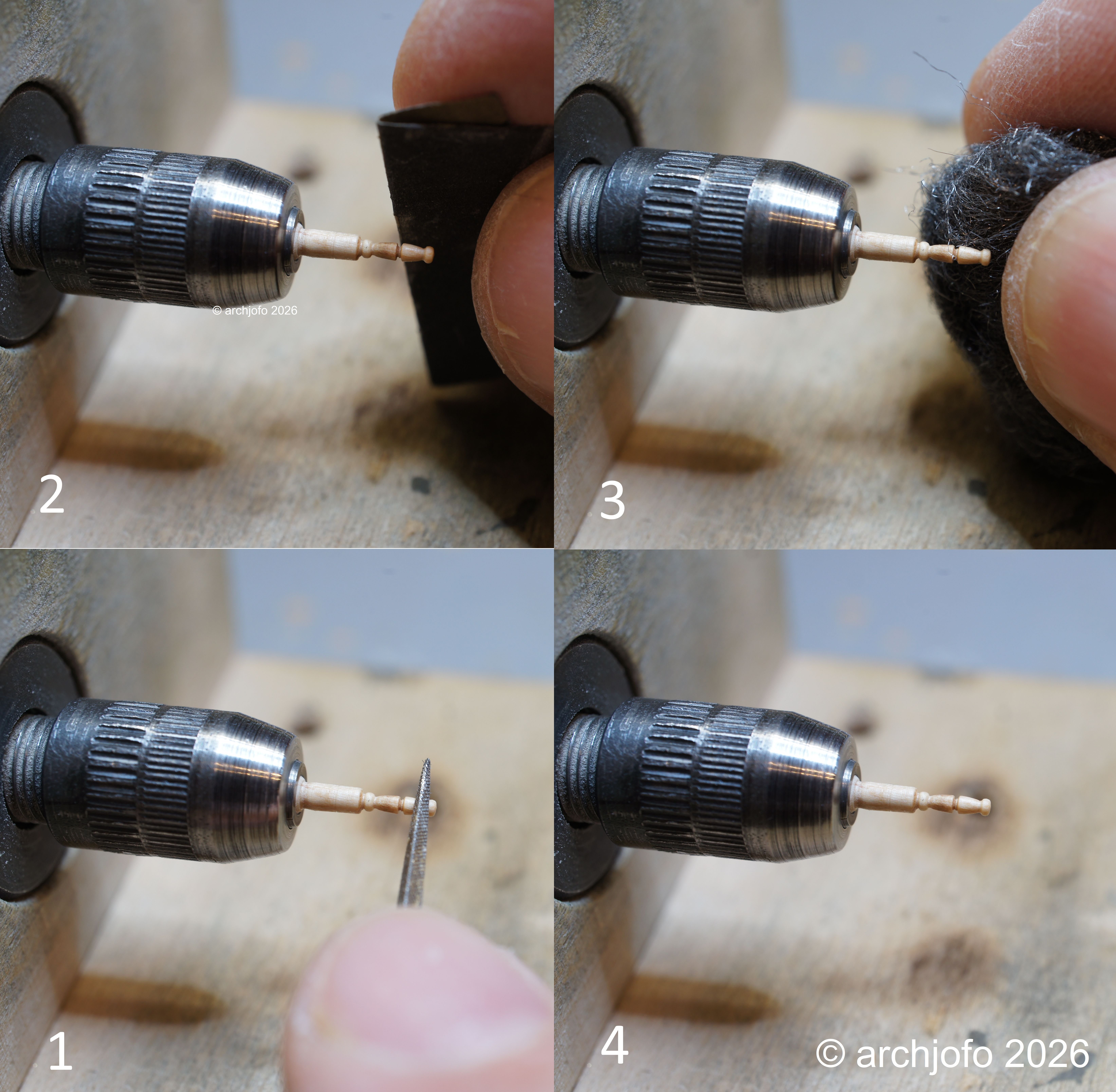
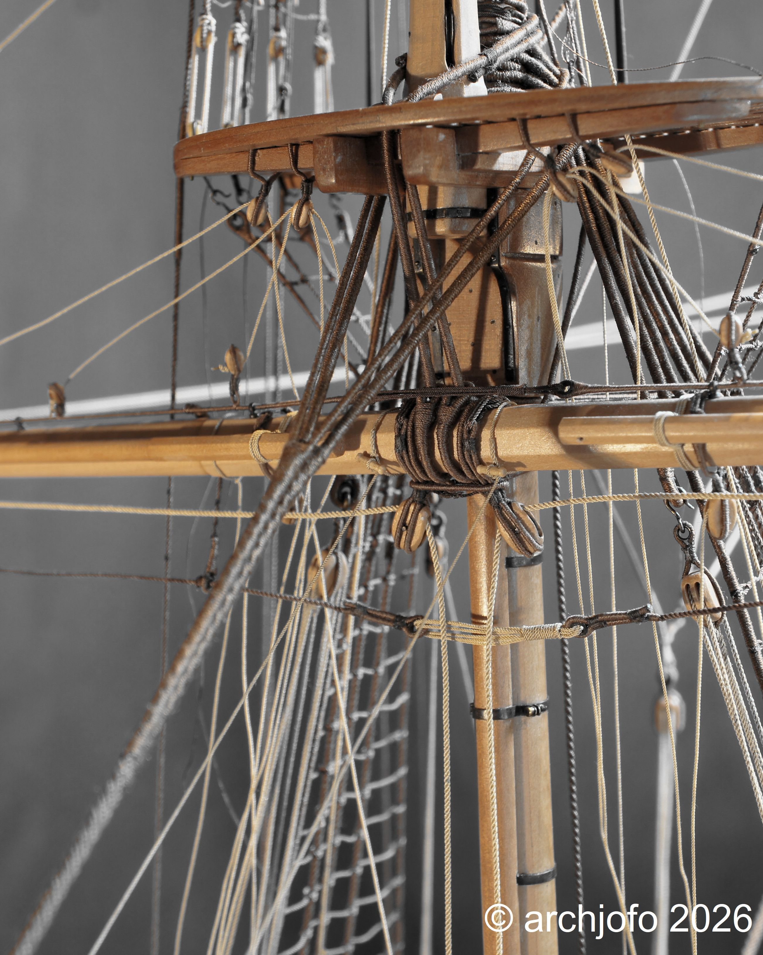
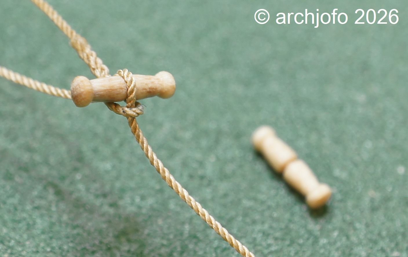
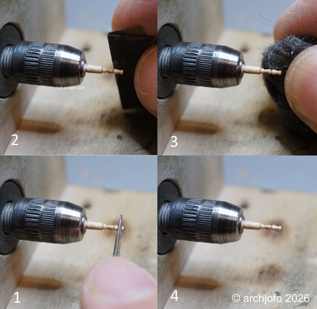
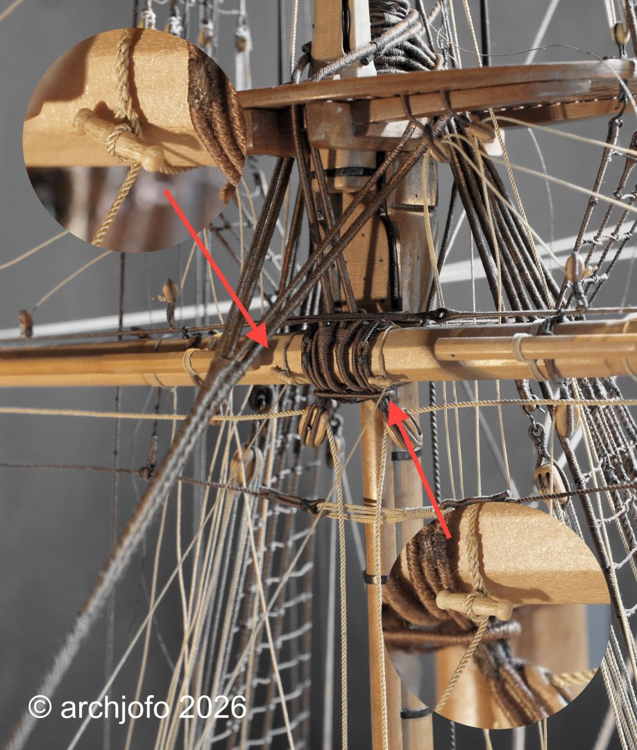
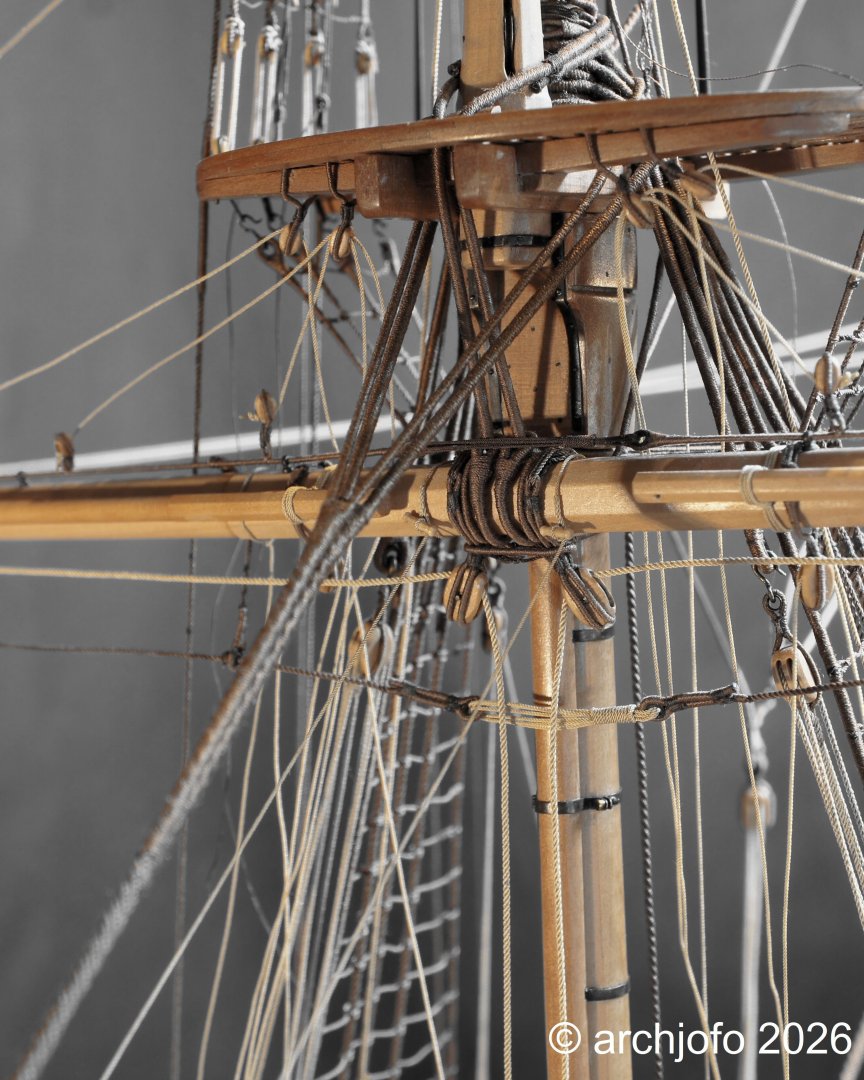
Continuation: Fore Yard Boulins – Boulines de la vergue de misaine After further research, I moved away from securing the boulins with the sails taken off in the way I had originally shown on the model. That earlier version followed English practice more closely: In the meantime, I have settled on the variant now implemented on the model, as it corresponds much more closely to French practice and is therefore historically more accurate. The following photos show the current arrangement on the fore yard in detail. Beforehand, during additional research, I systematically examined the shape and construction of the toggles. The compilation of different toggles illustrates the wide range of forms and manufacturing techniques — from simple wooden toggles of the Viking era to turned pieces from the 19th century. For the model of La Créole, however, the toggles documented on the models of L’Océan (1806) and La Créole in the Musée de la Marine are the most relevant. Both display a characteristic French design. The following images show how the toggles were made from dogwood. The wood is extremely hard and fine‑grained, making it ideal for these tiny pieces. The final close-up shows the toggle together with a rope that has been fitted with a fully scale‑accurate, real spliced eye — exactly as shown on the model. The splice ensures: clean load transfer without the bulk of a knot a scale‑appropriate appearance, since knots often look oversized on a model a historically correct connection, as can also be seen on the Paris museum model To be continued…


-
archjofo reacted to a post in a topic:
La Créole 1827 by archjofo - Scale 1/48 - French corvette
-
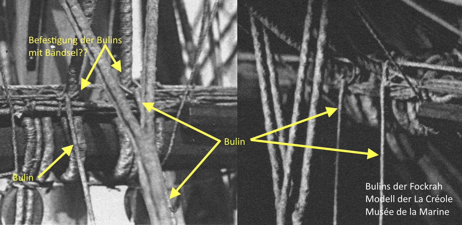
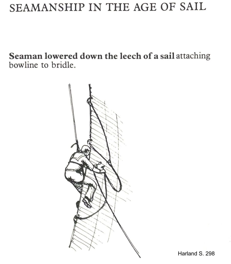
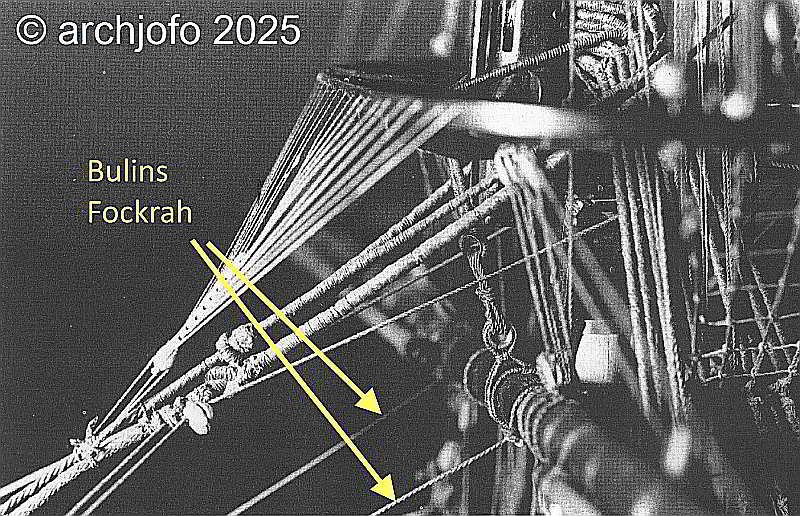
After a longer lull in my build log, the wind is finally picking up again – at least as much as a retiree’s heavily occupied schedule allows… 😁 Boulines on the Fore Yard – Bulins de la vergue de misaine The question of how the boulines were correctly attached to the fore yard – especially when the sails were furled – can, in my view, only be answered convincingly by considering several sources together. A helpful starting point is Harland’s illustration showing a seaman lowered along the leech of the sail in order to detach a bouline from the bridles. This scene makes clear how direct and practical these connections were in everyday use. On closer inspection, the bouline appears to be attached to the bridles by means of a toggle – a method frequently documented in early 19th‑century French rigging tradition, known for its quick handling and high reliability. A look at the museum model of La Créole in the Musée de la Marine is also instructive. There, the boulines on the fore yard are secured with simple seizings. Source: Musée de la Marine, Paris To me, however, this execution seems more like a modeller’s simplification. While many details of the model are rendered with great care and historical accuracy, the seizings in this particular spot appear to be a pragmatic choice by the model builder rather than a necessarily authentic representation of actual practice on board. That does not mean it could not have been done this way – only that it is not compelling evidence. A much clearer picture emerges from the main topgallant yard of L’Océan (1806). Here, the boulines are unmistakably secured to the sprits with toggles – an arrangement fully consistent with French tradition and entirely logical from a structural standpoint. Source: Musée de la Marine, Paris Interestingly, the model of L’Océan from 1806 shows both methods side by side: some boulines are clearly attached to the bridles with toggles, while others are simply looped around the yard with a fixed eye. The available sources do not offer a convincing explanation for this variation. Such inconsistencies are not unusual in historical rigging and likely reflect differing practical requirements or contemporary habits. A definitive interpretation is therefore not possible; the observation remains an intriguing but ultimately unresolved detail. For the fore yard of my model, these findings together form a coherent picture: attaching the boulines with toggles appears not only historically plausible but is supported by several independent sources. Moreover, the toggles on the bridles were present anyway when the sails were bent, so their use with furled sails seems entirely logical to me. For these reasons, I have chosen the toggle method, which aligns with both French practice and the technical logic of the rigging. As so often in historical rigging, a certain degree of ambiguity remains. My chosen solution therefore reflects my own source‑based interpretation without claiming to be the only possible one. Implementation on the model will follow shortly…


-
archjofo reacted to a post in a topic:
LA CREOLE/ LA GUADELOUPE by matiz - 1:48 - by Tiziano Mainardi from Boudriot plans
-
archjofo reacted to a post in a topic:
LA CREOLE/ LA GUADELOUPE by matiz - 1:48 - by Tiziano Mainardi from Boudriot plans
-
archjofo reacted to a post in a topic:
Brig Le FAVORI 1806 by KORTES - 1:55
-
archjofo reacted to a post in a topic:
Brig Le FAVORI 1806 by KORTES - 1:55
-
archjofo reacted to a post in a topic:
Brig Le FAVORI 1806 by KORTES - 1:55
-
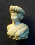
I wish you all a happy new year full of inspiration, patience, and joy in model making. May every project bring a piece of history to life. PS: The figurehead is, of course, hand-carved by me. Only the face… the Olympic god of beauty briefly intervened, because he thought my version was 'too realistic'…😁

-
Hello fellow model builders, Thank you so much for the likes and your kind Christmas wishes. I hope things will continue here soon.
-
@GeorgeKapas A beautiful model ship!
-
Hello, These are so-called timber hitches (see LINK ). A knot that was used in various rigging situations, including for temporarily securing the bowlines. However, this was primarily used in the British Navy, as already mentioned.
-
@Kenchington Hello Trevor, Thank you, very exciting that you experienced the Rose before her ‘career’ as Surprise. Your note on English practice complements the French sources wonderfully and makes the differences even clearer.
-
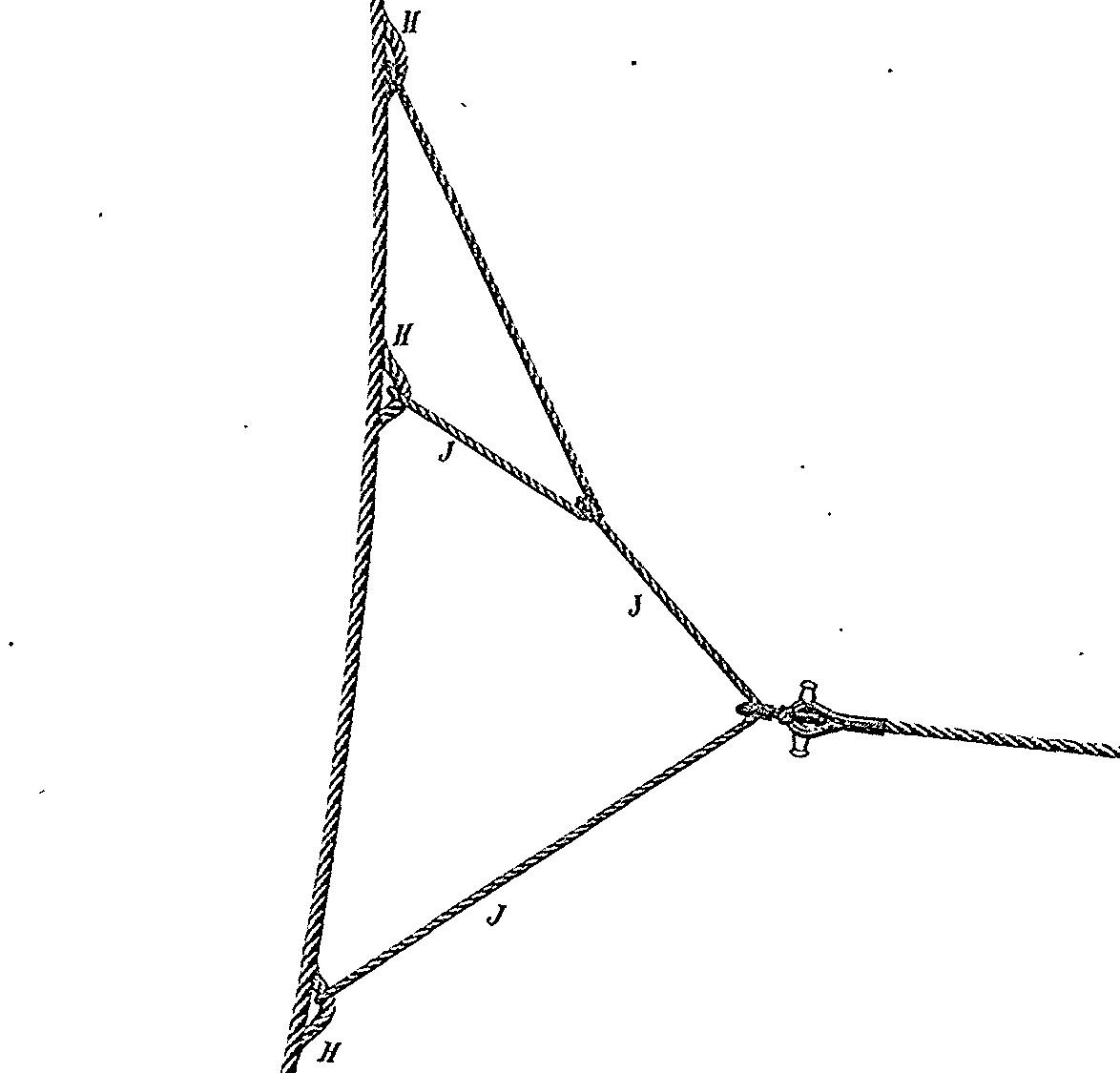
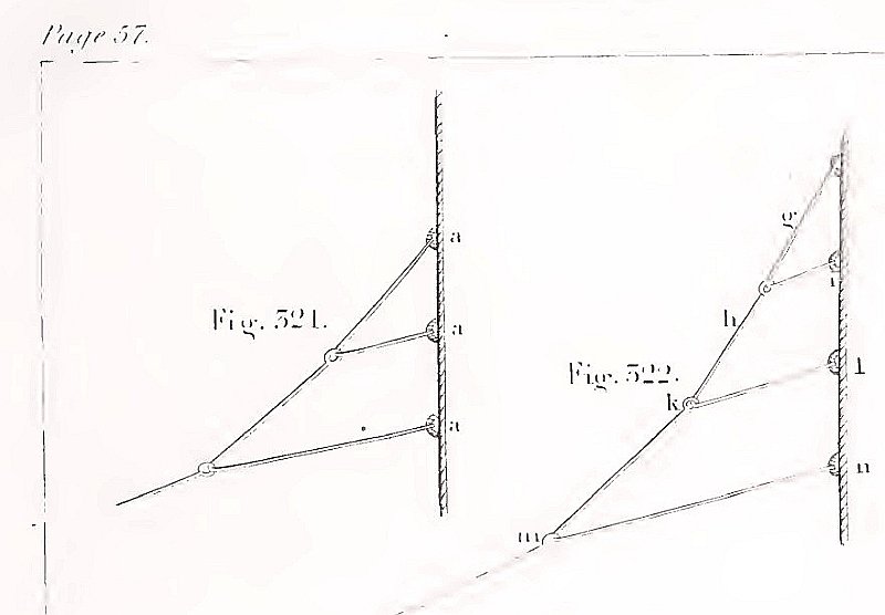
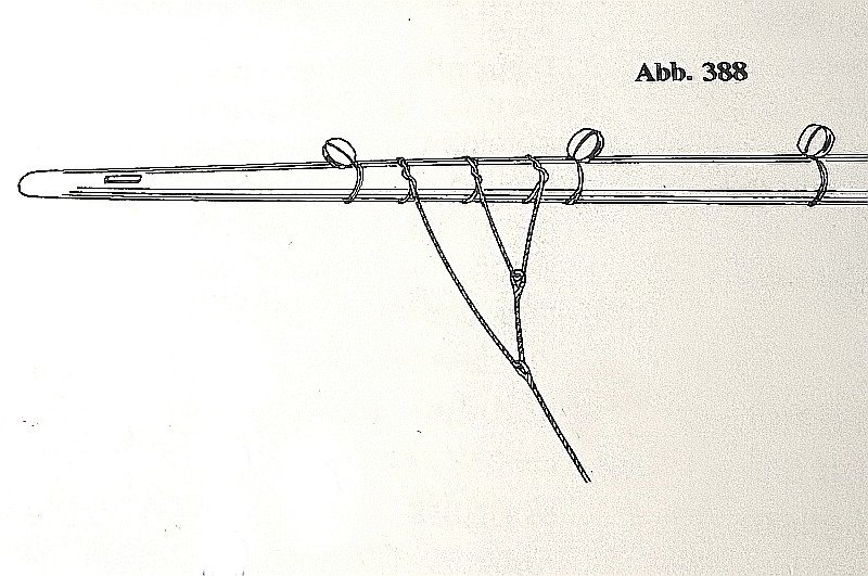
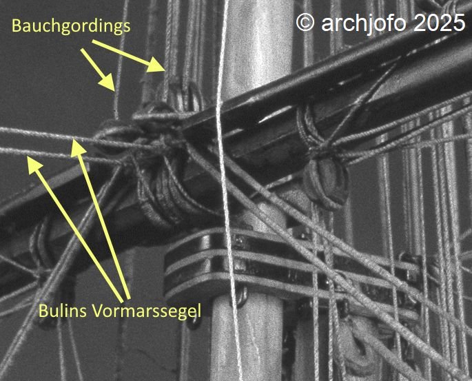
Bowlines and Bridles – Boulines et branches In continuing my research on the bowlines (boulines) for my French corvette, I came across an intriguing national distinction that manifests not only in theory but also in practical model execution. I have since identified a differing treatment of bowlines when sails are struck, between British and French practice. The aim of these measures was to prevent the lines from becoming entangled and to ensure immediate readiness when re-rigging. These differences are well documented in contemporary sources and observable in period models: a) British Practice: British manuals such as David Steel (1794), Darcy Lever (Sheet Anchor, 1808/1843), and Brady (The Kedge Anchor, 1841) depict bowlines fitted with spliced-in thimbles, through which the bridles were rove. Lever states explicitly: “The bowlines are rove through thimbles spliced into their ends, to which the bridles are attached.” Source: The Young Sea Officer’s Sheet Anchor, Darcy Lever, p. 57, 1843 Accordingly, the British rigged the bowlines together with the bridles to the outer yardarms. This arrangement was certainly robust, but less flexible when striking sails, as bowlines and bridles had to be handled as a single unit. Source: K. Schrage – Rundhölzer, Tauwerk und Segel, p. 144 b) French Practice: Baudin (Manuel du jeune marin, 1828) notes that bowlines were rolled up and secured to the mast or yard after the sails were furled — “roulées et assujetties au mât ou à la vergue.” He does not elaborate on the exact method of securing them to the yard. However, his description suggests that the bridles remained attached to the sail. This interpretation is supported by illustrations in the Atlas du Génie Maritime, where bowlines are shown fastened to the bridles using toggles. This solution facilitated rapid bending and unbending of the sails. The bowlines of the mainsails require separate consideration, as discussed in a previous contribution of mine. Source: Atlas du Génie Maritime On the period model of La Créole, as well as on numerous other models in the Musée national de la Marine, one can observe bowlines secured amidships on the yards, without bridles. In the case of La Créole, the bowlines in this example appear to be connected to the buntlines via eye splices or stopper knots, and thus stowed securely. Source: Detail from the original model of La Créole, Musée de la Marine, Paris Source: Detail from La Flore, Frégate de 18, Musée de la Marine, Paris, 1806 Personal Conclusion: The French employed toggles at the bridles and secured the running ends of the bowlines amidships on the yard, where possible, e.g., in conjunction with the buntlines — in my view, a practical solution that facilitated swift re-rigging. The British, by contrast, preferred spliced-in thimbles at the ends of the bowlines, through which the bridles were rove — a permanent and solid connection, but likely less flexible when striking sails. This reveals a clear national differentiation, as seen in many other rigging elements. As a result, I now need to revise the detail of the bowlines on the fore yard, which I had mistakenly and prematurely executed in analogy to British practice. It seems important to me that such details shouldn't be viewed too absolutely. Depending on the ship type, time period, or source, different solutions may have existed side by side—and therefore, variants that deviate from the "schema" are not automatically wrong. I welcome any feedback or additions — especially references to French sources that further illuminate the use of toggled connections.

-
@matiz These plans look familiar to me...😁
-
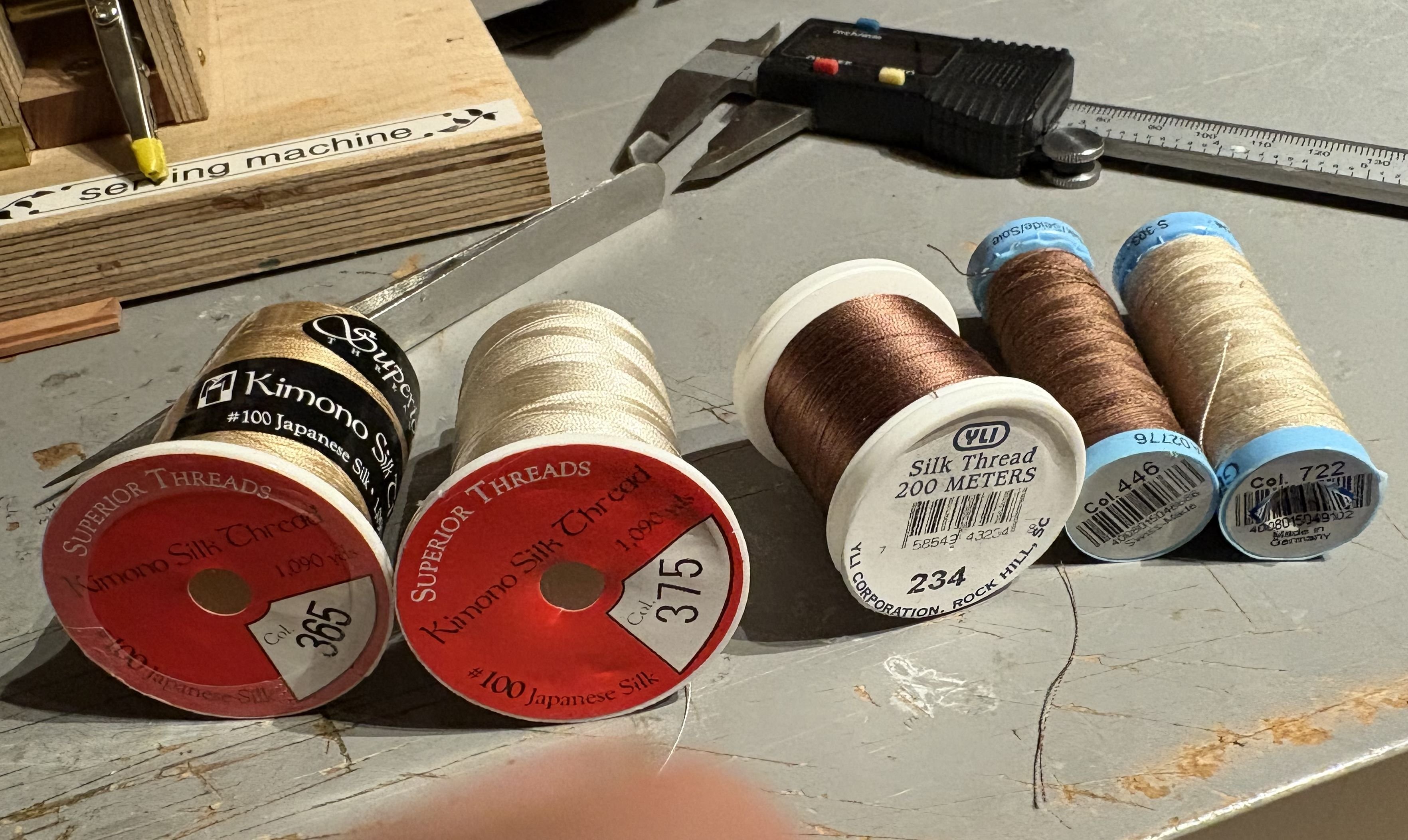
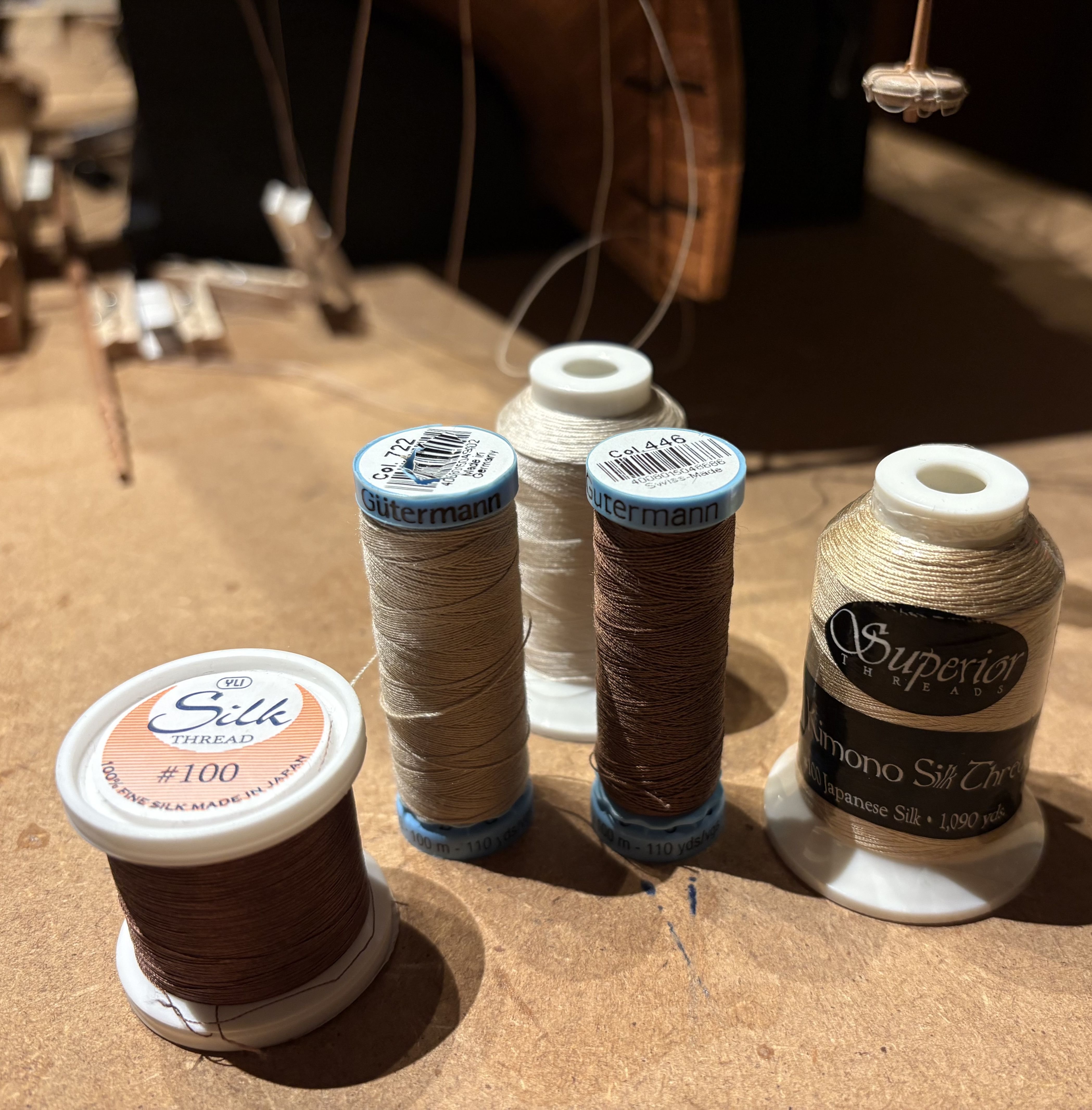
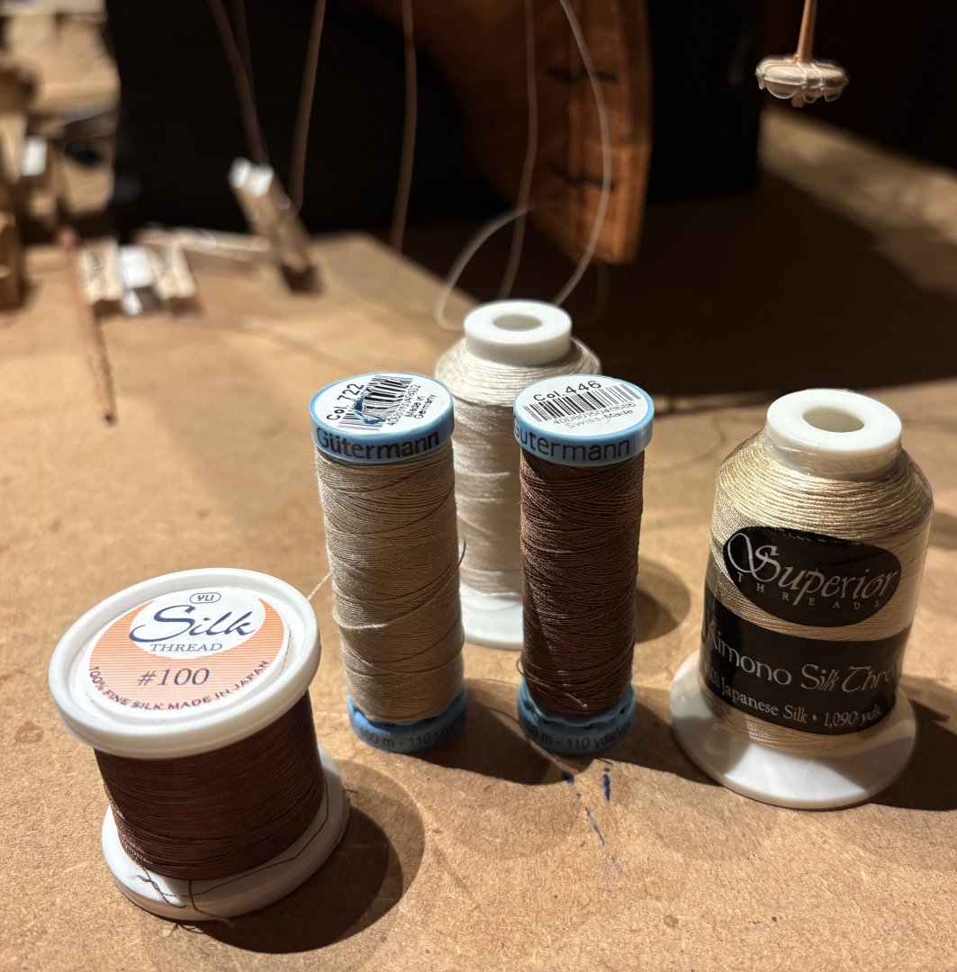
@Loracs Hello, No problem, of course I'll show you which yarns I use as the raw material for making my ropes. It's silk yarn, which isn't entirely undisputed in terms of durability. Nevertheless, I chose it because, in my opinion, it's the ideal raw material for model ropes. You can read an interesting post by Greg Herbert about the use of silk in model making and in general in my topic: LINK I use silk yarn from Gütermann, Ylk, and Kimono. The following pictures also show the color numbers used. If you have any further questions, please feel free to contact me.

-
@Pirate adam Hello, Thank you very much for your appreciative words—they truly mean a lot to me. Regarding your generous remark about this build log becoming a “valuable resource on rigging,” I’d like to add a small clarification: just as with ship construction, rigging practices must always be understood within their specific historical and geographical context. My research and conclusions are focused on the early to mid-19th century, particularly within the French naval tradition. Sharing these findings feels natural to me—especially since I continue to benefit greatly from the many outstanding build logs and discussions here on the forum.
-
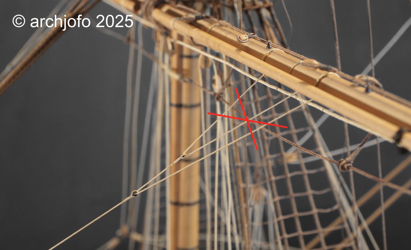
Rigging of the Mainsail Bowlines – Boulines de grande voile In the meantime, I have been able to clarify the principle of how the mainsail bowlines were rigged on my French corvette through the study of contemporary technical literature. It is important to maintain both the chronological and geographical context. My findings are consistent with the observations made on the period models in the Musée national de la Marine. The mainsail bowlines were led through snatch blocks (fr. poulie coupée), which were attached amidships on the deck abaft the foremast and belayed, for example, at the pin rail behind the foremast. Since the mainsail bowlines of larger ships required considerable force, they were usually double-purchased. Accordingly, blocks were fitted at the ends of the bowline bridles through which the bowlines were rove. Whenever the bowlines were not in use, they were unrove from the snatch blocks. Whether La Créole actually carried double-purchased bowlines could not be determined with certainty. What is decisive, however, is a finding from contemporary literature: The mainsail bowlines were not permanently rigged, in contrast to those of all the other sails. They were only bent on when actually needed; otherwise, they were kept ready for use on the foredeck. Source: Nouveau Manuel complet de Marine by M. Verdier, Capitaine de Corvette, Paris 1837, p. 175. This also explains why, on the period models (rigged without sails) in the Paris museum, bowlines are always to be seen on the other yards – but never on the main yard. The same applies to the original model of La Créole. For this reason, I will consequently not represent mainsail bowlines on my model. Nevertheless, for illustration, I show here how the rigging of the mainsail bowlines would have looked in principle: Source: Manuel du Gabier, Paris 1875.
-
@druxey @wefalck @JerryTodd Hello, I would like to expressly thank you for your precise and helpful contributions on the question of the routing of the mainsail bow lines. The different perspectives on historical practice, especially in the English context, as well as the technical information on possible interference with the headsail rigging, have greatly helped me to consider the issue in a more nuanced way. Your assessments contribute significantly to critically questioning the plausibility of the solution presented in Boudriot's monograph. I will incorporate the suggestions into my further planning and look forward to further discussions.