HOLIDAY DONATION DRIVE - SUPPORT MSW - DO YOUR PART TO KEEP THIS GREAT FORUM GOING! (Only 51 donations so far out of 49,000 members - C'mon guys!)
×


ianmajor
-
Posts
784 -
Joined
-
Last visited
Content Type
Profiles
Forums
Gallery
Events
Everything posted by ianmajor
-
 Mike, Good point about the gammoning. I had already cut the prow and assembled the structure around it to take two lots of gammoning before realising that it was wrong.
 -
Tadheus, Thanks for this. It looks very interesting. I have bookmarked the link so that I can look at it in more detail later.
-
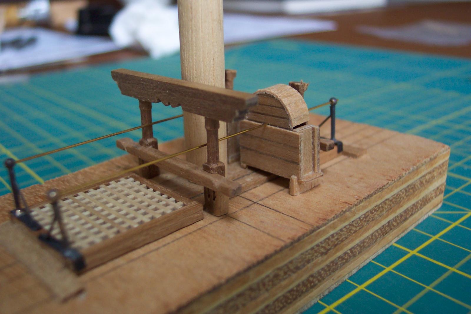
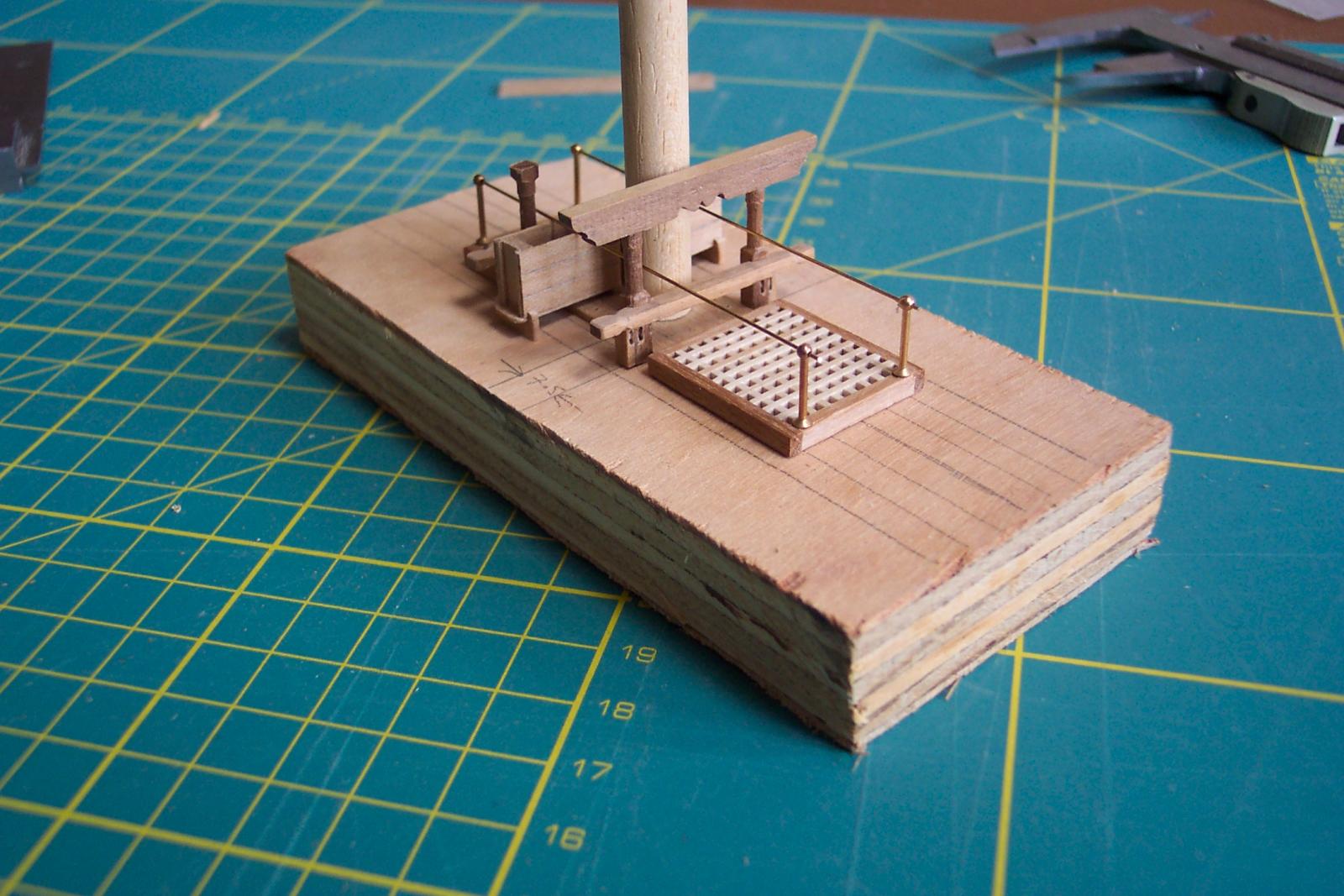
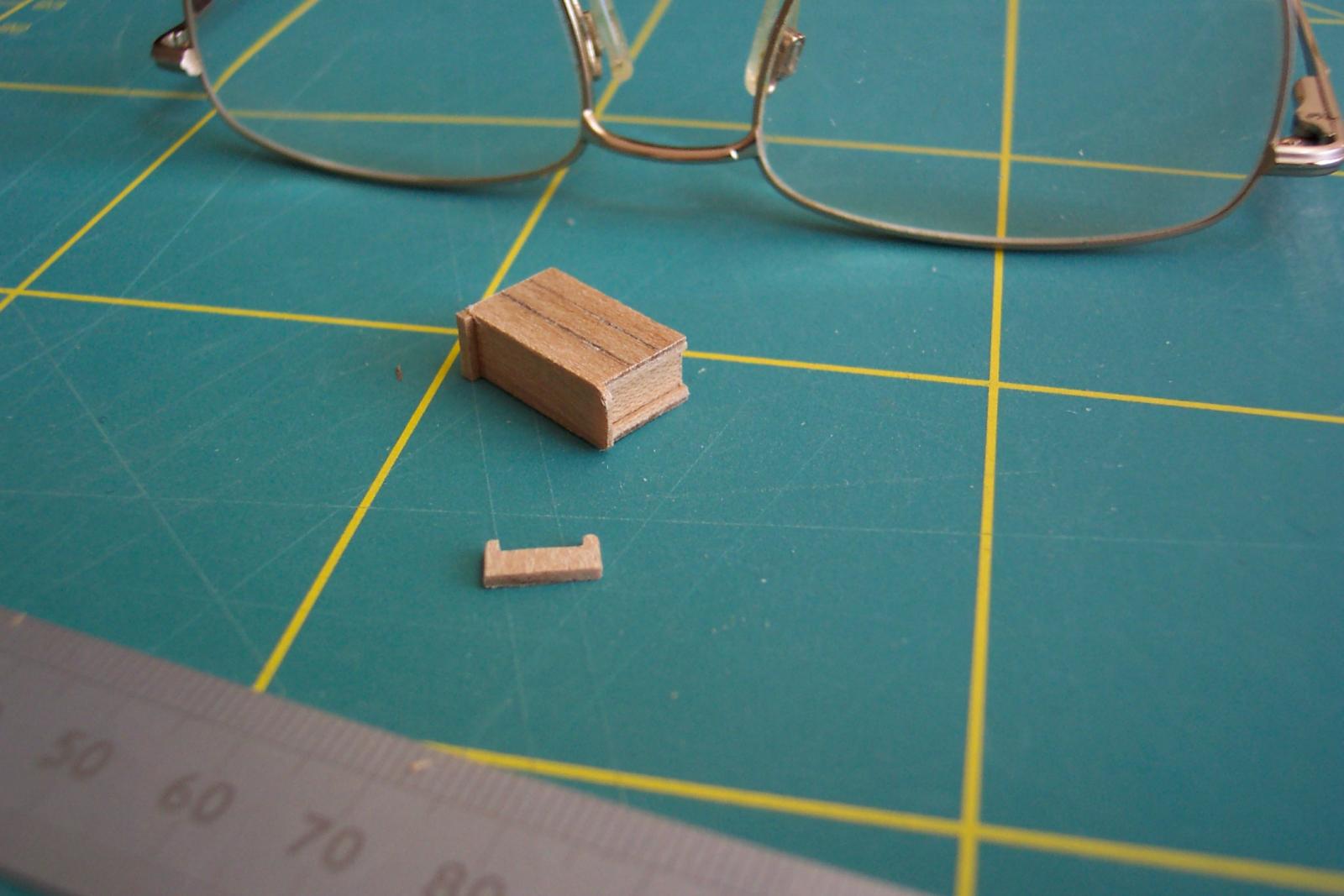
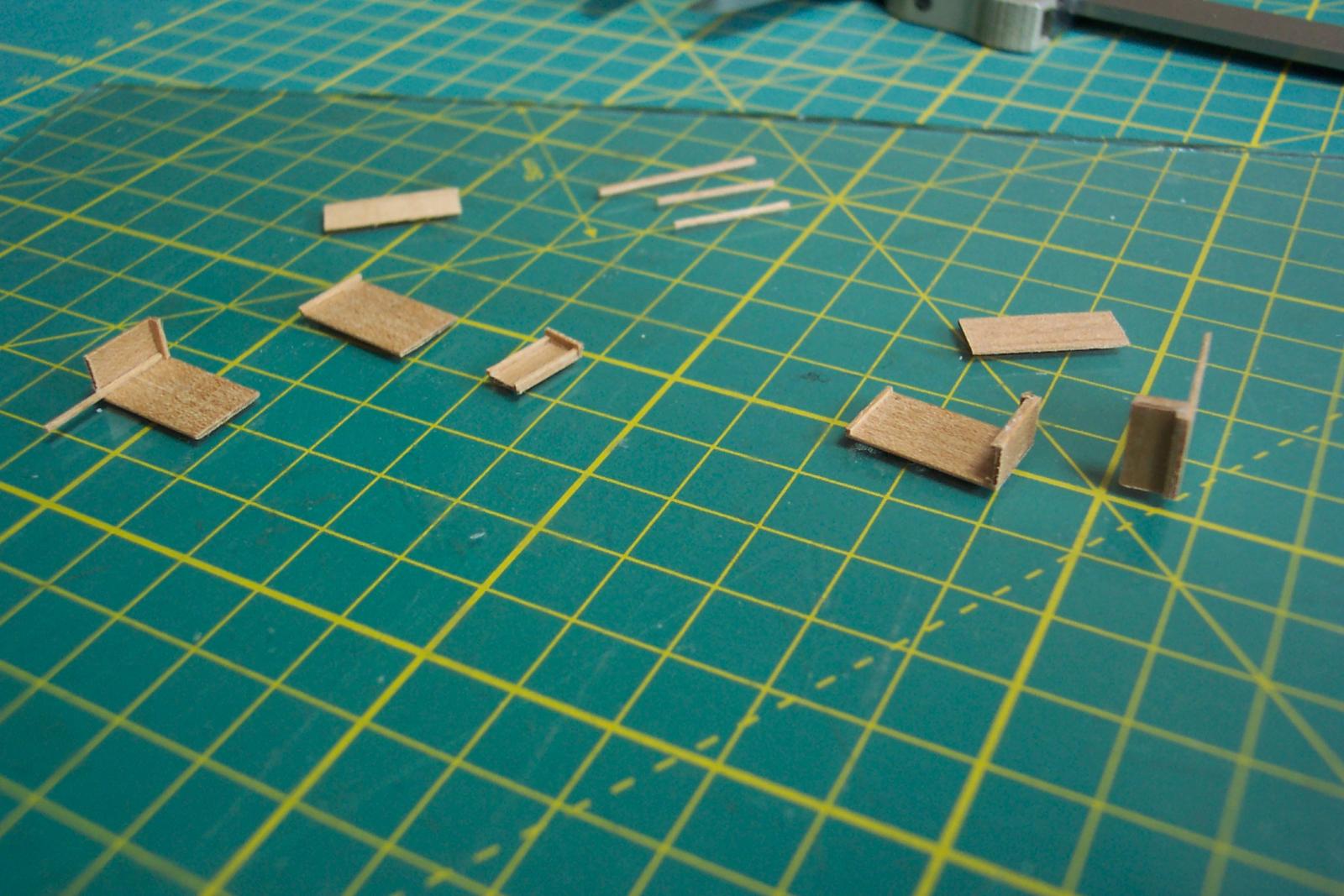
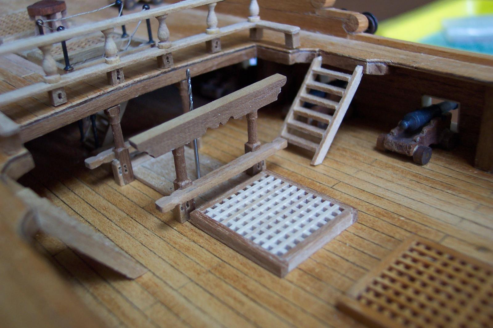
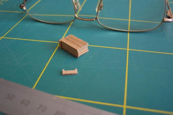
Then I tried the four braced stantions in place. They are blackened but need a polish up - they look rather uneven at the moment. Having got the centre line of the cranks established it was now time to check the lateral position of the pump cisterns. The easiest way was to make the hoods and use their centre lines when fitted to the cisterns. To make the hoods I cut the sides from 0.5mm thick walnut. The edge planking was 1.5mm wide strips of the same material.The sides were made so that they made a sliding fit inside the cisterns. The hoods when complete will rest on the edge planking. I milled a piece of scrap wood to be a snug fit inside the hoods to use as an assembly jig. This piece had a 0.7mm hole drilled in it so that the sides could be lined up using the 0.7mm drill bit. With the sides clamped to the jig I checked that it would still slide inside the cistern then I to planked around the edge. The first hood and a cistern were again tried for alignment. Once I am happy with the ride height of the hood I will fit a closure plank on the gap that still exists on both sides (the nearside gap is visible). Now it is time to make the second hood. I intend to have a pump with the chain and sprocket visible. Making two hoods means that if I make a complete pig's ear of the chain I can glue the two hoods on and pretend that that was what I intended to do all along!


-
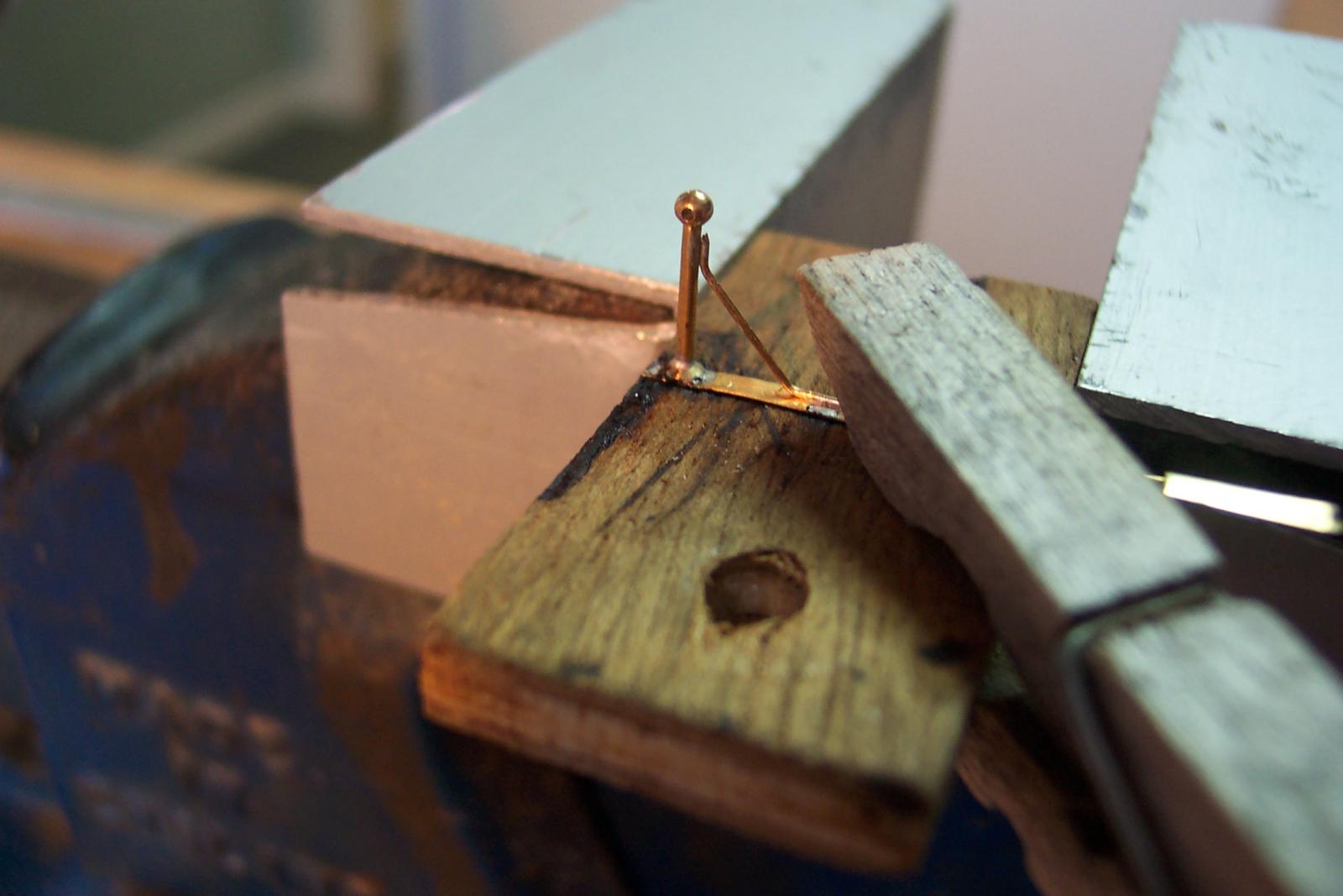
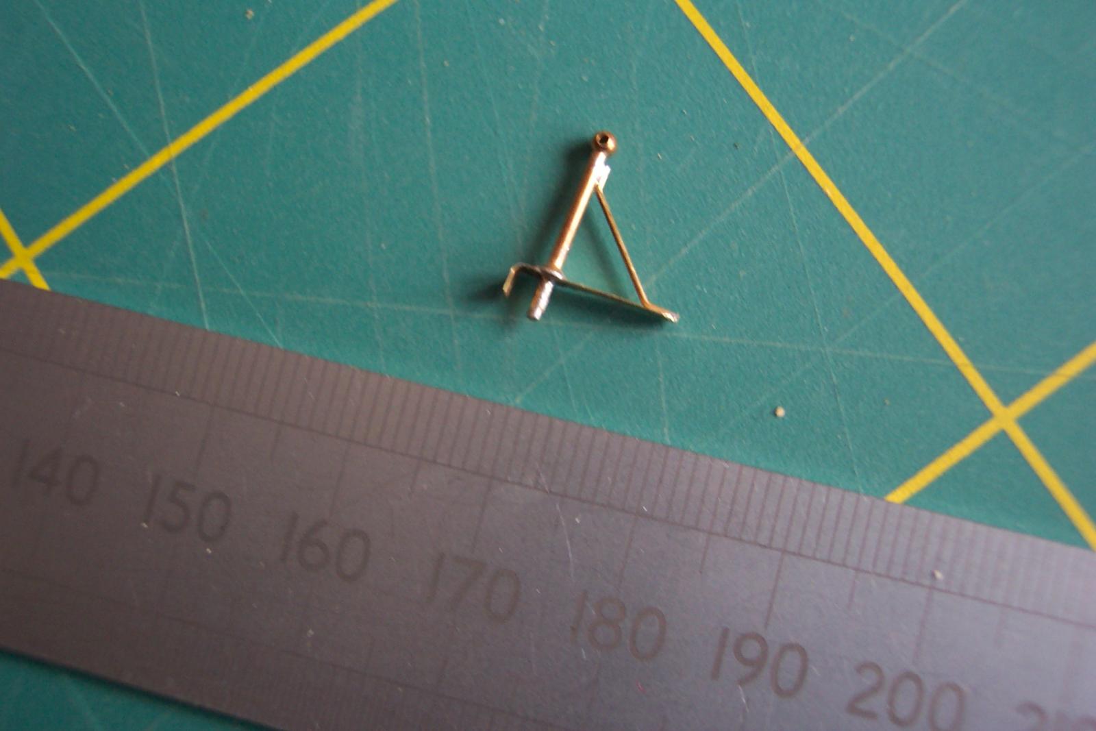
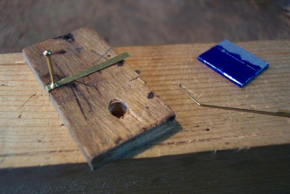
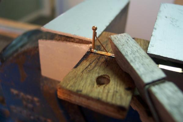
I am off to Edinburgh for a about 4 days with my wife and will not have Web access. So I thought a quick update was the order of the day. I am now the proud owner of a (second hand) copy of Lees. Now I will have to think up new excuses for getting the rigging wrong. For the end supports for the cranks I decided to use and modify four of the redundant stantions. First I drilled the end pieces of the gratings to take the stantion pins.Then I did a trial fit using temporary pieces of 5mm brass rod to ensure all would line up. In fact I had to slightly elongate the holes to achieve this. For the modification I cut a 2mm wide strip of brass shim to make the bases. For each base I drilled a 1mm hole 5mm from the end of the strip. I made a simple jig - a piece of plywood with a 1mm hole 2mm from the edge. The shim was trapped on to the jig using the stantion then the end of the shim bent over the edge of the jig. I made a second jig to bend the 0.5mm wire that would make the brace. This consisted of a piece of scrap aluminium with a hole drilled 9mm from one edge. The wire was insert in the hole, bent towards the edge of the aluminium then bent over the edge. Using a protractor as guide I set the two bends to 45 degrees. This jig ensured that all four braces were identical. At this stage I did not cut off the base or the brace from the source material - this made them easier to hold when soldering. Next up I clamped the wooden jig in the vise and soldered the stantion in to the base - making sure the hole was pointing in the right direction! Next using a clothes peg I clamped the brace in place. This only required a touch from the soldering iron to secure both ends. The base was then trimmed and its end rounded with a file.


-
Mike, Beautiful work. You will definitely need to rest your eyes after completing those decorations.
- 137 replies
-
- 2
-

-
- finished
- model shipways
- (and 1 more)
-
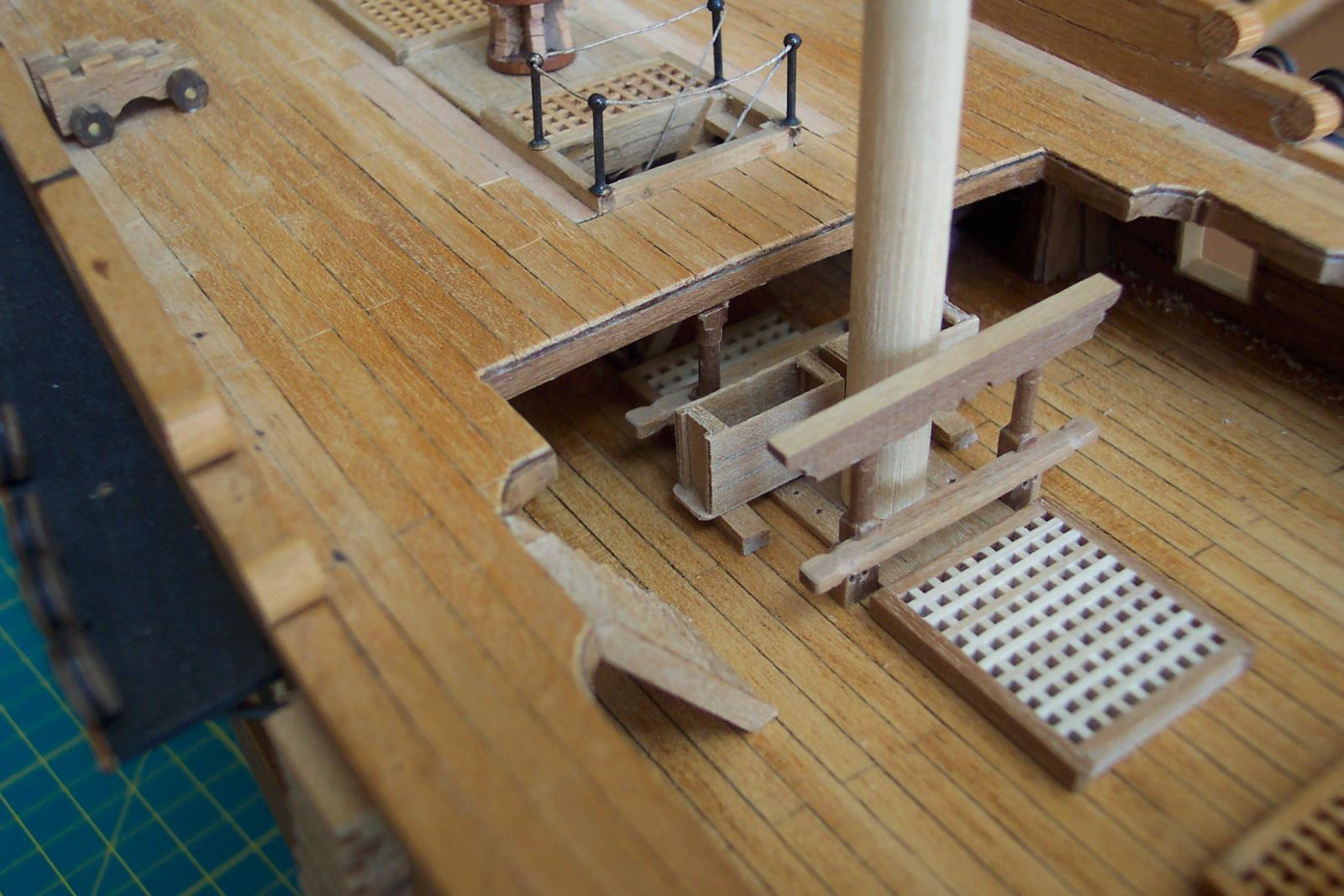
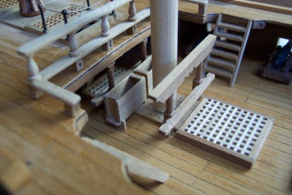
The outboard feet were then cut from 8.5 x 1.0mm walnut strip (the grain runs vertically). The feet were then glued to the cisterns. I will shape the bottom of the feet after I have varnished them. Then a family group photo. I put the cisterns with other bits in the waist to make sure they fit together and that the cisterns remained level. At this stage most of the deck furniture in the photo is still dry fixed.

-
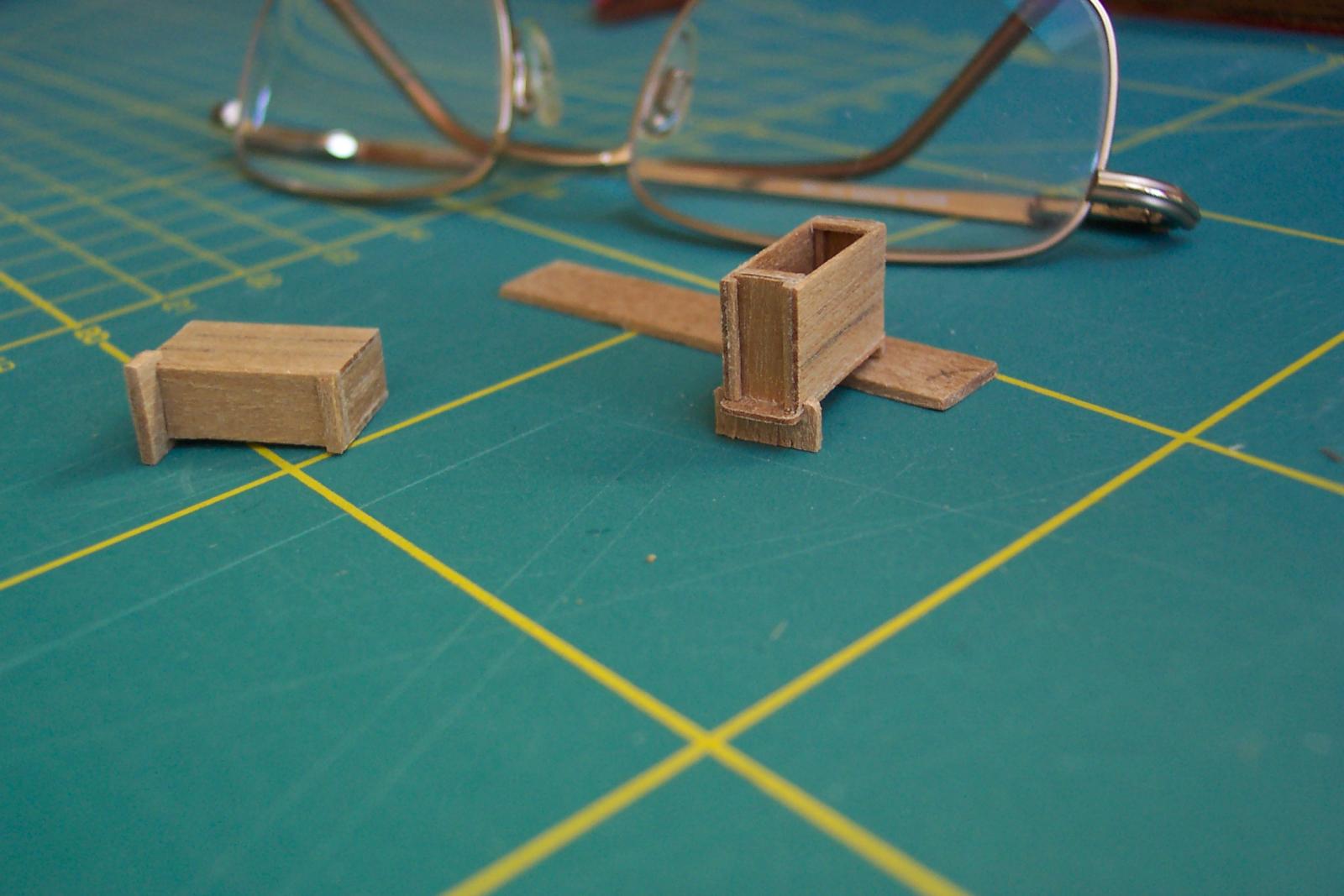
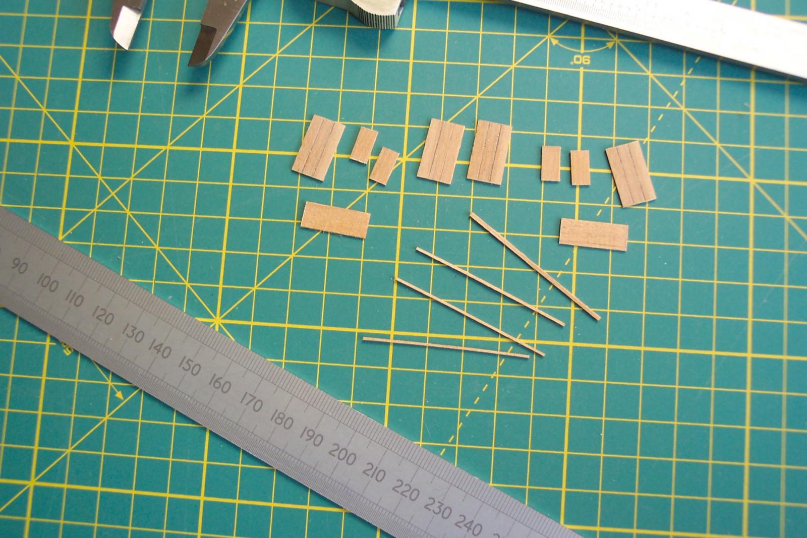
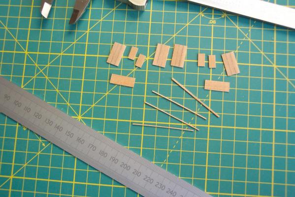
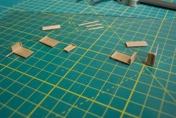
Thanks Joe. Nice to know my thinking is not totally off the rails. Time to get stuck in to the chain pumps - starting with the cisterns. I started by preparing some 0.5mm thick strip of walnut with my "contraption". For the sides I produced strip 10mm wide. Along this I scored two groves and rubbed pencil lead in the them. This was to represent the edges of the planking. The strip was then cut in to 17.5mm lengths to make the four sides. Similarly 4 off pieces 5.2mm by 10mm were cut from the ends (not from the same piece as the sides since the grain does not run in the same direction. Then 2 off pieces 6.5mm by 19mm for the bottoms. Actually I cut these slightly wide then trimmed them back when it was all glued together. Some other bits that I cut from this wood were 3 pieces 0.5mm square (to reinforce the corners and to make the slides into which the removable end fits) and one piece 0.5mm x 1.5mm to make the ledges on the top of the cistern at each end. Assembly was by fixing the slides to one end of each side. Next was the corner bracing to the two fixed ends along with a piece of 0.5 x 1.5 x 5.2mm to make the ledge. Each end was then fixed to one side. These parts were then glued together and the bottoms were glue on with one end protruding from under the removable end. When dry the bottoms were trimmed to the correct width and the protruding end rounded. For the inboard end of the cistern the feet were made from 6.5mm lengths of 1.0 x 1.0mm strip. These were glued across the width of the cistern (one per cistern). The cisterns were then placed in the waist area and the outboard ends were packed with scrap wood until the cisterns were level. Measuring the thickness of the packing gave me the depth of the outboard feet.
-
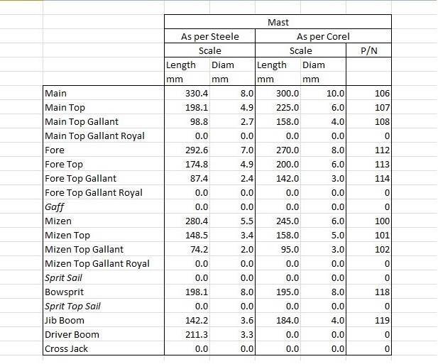
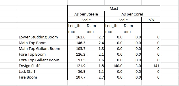
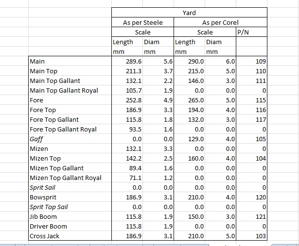
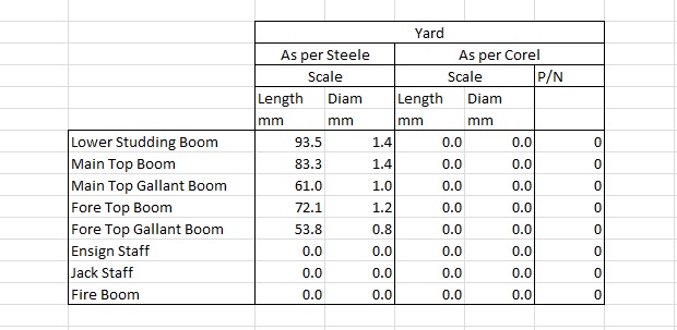
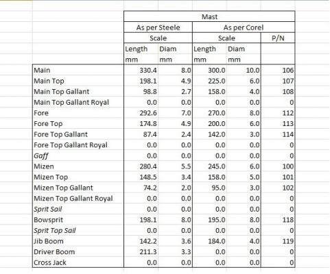
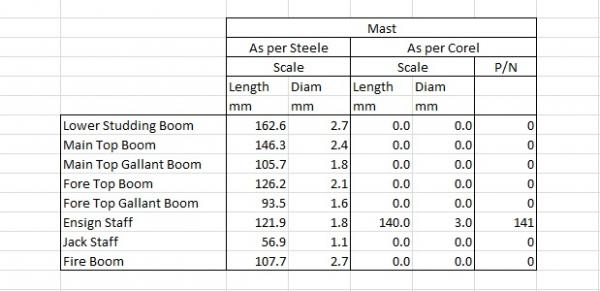
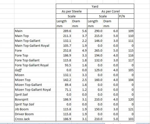
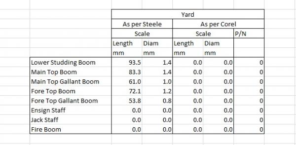
OK, Using Joe's idea here is an extract of the comparison table that I produced. One input was from a table in Steel that covered a 500 ton 28 gun frigate and the other input was from the Corel sheet that gives the dimensions of the masts and yards. This extract compares the Corel metric scale sizes with the metric scale sizes calculated from Steel. The P/Ns refer to the Corel part numbers in the plans. The Corel mast lengths will not include that part which extends below the upper deck, but even so there are a lot of differences. Anybody have any thoughts (apart from my sanity or lack of)? I want to get the lower parts of the masts made before finishing off the deck furniture to make sure it all fits together.
-
Mike, I have been revisiting (yet again) the Lyme plans. I see something extra every time. I now see that it shews the tiller above the quarter deck rather than between decks as depicted by Corel. That would be a really good feature and also another reason to ditch the flag lockers. Your Pegasus plans would help here though the Lyme appears to have a curved beam in front of the tiller to guide the rope (an illustration in Lavery shews how this works). Sadly, in my case, taking the rear end apart to add this feature is perhaps a step too far. It is sad the original Unicorn diagrams were "lost" - they would have had so much more detail than that produced by Chapman.
-
Joe, Thanks for the kind words. If my Unicorn comes out any where near as good as yours (and your Prince De Neufchatel) then I will be very happy. Re doing a screen capture - good thinking I will try that.
-
Mike, I think the Unicorn would still be a good step towards Pegasus. If you are (in the unlikely event) going to make mistakes would it not be better to make them on the Unicorn?
-
Mike, As you have probably now found the masts are only held in place by the holes in the quarter deck/fore deck piece. This allows a lot of "adjustment" in all sorts of directions. From your photos the bulkhead issue does seem to have been fixed in later versions of the kit. It certainly caused me pain - and was very much like Rafine's experience with his Essex. If you open up the waist in the same way that Joe did you will retain the original main mast hole. I cut the quarter deck to behind the main mast, so I had to re-establish a hole for the main mast on the upper (main gun) deck. This does drill in to the keel piece so care has to be exercised when drilling to stop the drill bit wandering down one side of the keel or the other. If you are going do do the same as me you could prepare for that now by cutting a slot in the keel piece and drilling a corresponding hole in the gun deck. The question is - what diameter hole? The mast diameters and lengths as per Corel are somewhat bigger than indicated by Steel. I am trying to work these out for my ship! Would have used Dan Vadas' spreadsheet (in the MSW downloads) to work this out but my Excel does not support the macros used in it. I will drop you with a PM in the next few days with the calculations that I have already done.
-
Mike, I agree with Joe on using just the fore deck and quarter deck part of the deck template. Two reasons. 1) The piece needs to sweep/curve upwards fore and aft but curve downwards from beam to beam (for the camber). This puts the centre line of the piece under compression and the side edges try to stretch. It doesn't work well. 2) As you noted you will get a thick piece of plywood showing under the gangplanks - which should be quite delicate looking. Since mine was already in place I chamfered the edges to hide this in the hope that nobody would notice (or were too polite to say anything). You can also have the gangplanks at a slightly lower level than the fore and quarter deck which seems to fit in with all the contemporary models. When I cut the middle out of mine I used the leading edge of the existing waist hole as a datum line across the ship, and made all my measurements back from there. This seemed to work OK. On the hull planking, as you say, the plans show the planking extending right back to the rudder. I think this is meant to simplify things ie avoiding a rebate/rabbet for one thing. Though my (ancient) kit supplied mahogany strip for the second planking and it was the devil's own job around the buttocks to get it to twist from near horizontal to vertical in the distance of an inch or less to achieve this. If you can fit a stern post it will look much more the part. I notice on some renditions of the Unicorn the builders have planked along the edge of the keel piece to hide the exposed plywood layers. Your proposal will fix this. ZyXuz's point about checking the fit of the bulkheads is a good one. Certainly if you look at the photos of mine you will see there is hardly any keel showing along the bottom below the planks. As a result I can't hold the hull in a clamp to work on it. Some of my bulkhead parts extended below the keel when the tops were lined up - this has hopefully been corrected in later kits since mine was one of the first batch. On the subject of bulkheads you will note the ones that extend above the front and sides of the fore deck curve quite sharply outwards towards the top. I am not convinced that this is right - but I might be wrong in that view. It certainly makes life very difficult in this area.
-
Mike, On my trip to the Manchester Central Library I spent a happy afternoon reading through Lavery. On the ship's boats ( page 231) he says that during the period in which this Unicorn existed a frigate of 28 to 36 guns would have had 3 boats being:- 1) 21 or 22ft longboat. 2) 28ft pinnace 3) 22 or 23ft yawl Some interesting stuff to scratch build there! As a subject close to my heart ( ) I also checked on the stove sizes. He has a table page 198 that gives the appropriate sizes for the different types of ships. For the 28 gun frigate the stove would be 4ft 6ins long and 5ft 3ins high (to the top of the hood). However yet another close examination of the Chapman diagram suggests the stove should be on the lower deck not the upper (main gun) deck ie totally out of sight. Oh well. If this was so it must have been dreadfully difficult for the cook with the very restricted lower deck headroom on the Lyme class.
-
Ah yes - I can see a lot of changes there. The waist is wider. The quarter deck rail is in front of the main mast. That along with the beams across the waist and the configuration of the rigging looks very like Petersson's description of frigate rigging (though there are differences on the rear edge of the fore deck). Nice view.
-
Mike, It is good to see other Unicorns making an appearance. Joe V's seem to have quite a few changes in the rigging. The waist area also looks to have been widened to allow ships boats to be fitted side by side. Looks good. I had followed Peter Visser's log, which contained some useful entries on the rigging, but sadly the log was lost with MSW 1.0. At least there are the photos in the gallery. My ancient version of the kit did not have enough belaying pins to cover the Corel rigging scheme. Even if it had there would be nowhere near enough to cover full rigging. The Corel scheme is rather simplified. I have been looking at the contemporary models and there seems to be a total abscence of belaying pins - the running rigging being (apparently) belayed on the rails of the open bulwarks. I going to have a look a Lees to see what his view is on this. In the middle of the 18th century there were a lot of changes. The Unicorn and the Lymm were first of their type - so who knows - they may have led in the "technology" changes.
-
Mike, If you get rid of the lockers you will have to modify the keel and the one bulk head. The stern end of the keel sticks up above the quarter deck line. The piece of ply used for the deck will be a little short - but that is no great shakes. The arched windows reach up in to the locker area so would definitely need replacing with square ones. Personally I think getting rid of the those lockers is a good move. You will then be able to add a couple of stern chaser ports.
-
Mike, Thanks for the offer. Actually I hardly use the Corel plans now I that the hull is complete - I am tending to use other sources. I will try not to confuse my railway literature with the ship stuff else I will end up with a very strange creature indeed!
-
Hello Mike, I am getting slow these days. I didn't notice that you had started the Unicorn log. Got my "follow" on so it is time for me to catch up. I notice the plans have been completely redrawn since my version of the kit was produced. The latter drawings are far better - for example there was no head on view of the bow structures which made life difficult. Looking forward to your progress on this build.
-
Wow ZyXuz, That is some great work. It is hard to believe that it is from the Corel kit! Good to hear that your father is better (and that you are still alive and kicking! )
-
Mike, You are producing a very nice model - excellent work. I was interested in your photo of an actual boat's frames and that they were very thin. I was in my local library looking at Lavery's "The Arming and Fitting of English Ships of War". On page 212 he refers to the two types of planking (if I understand correctly) as:- 1) "Clinker" is where the planks over lap. He states that in this case the planks were assembled on a mould and the frames were added after - the frames were very thin - as in your photo. 2) "Carvel" the planks did not overlap. In this type the frame was assembled first and the planks added. In this case the frames were thicker.
-
Peter, As with the Unicorn your rigging is fabulous. This is a lovely little model. You are getting close to completion, have you decided on the next project?
-
Thanks Mike, though I don't think mine is a hard act to follow! Hopefully I can demonstrate a few things that are or (more likely) are not possible on this beast. At least anyone deciding to do these modifications as the ship is built rather than carve in to old work will have a less stressful/traumatic time. I am keeping an eye out for the start of your Unicorn build log - now that IS going to be good.
-
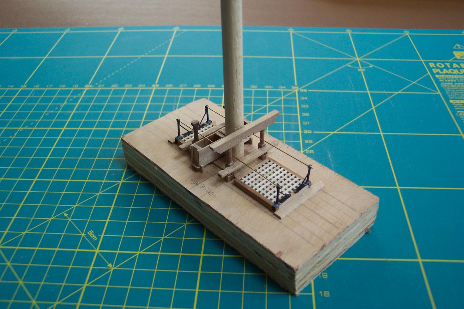
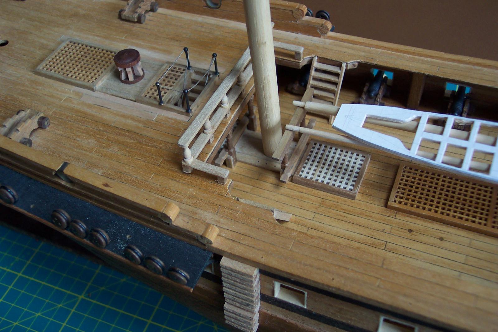
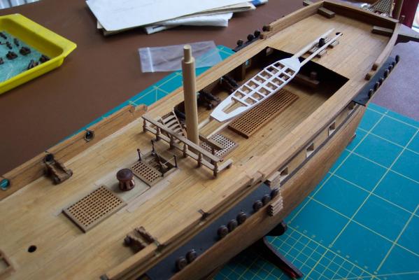
I turned a stub main mast to ensure it would clear the bits. I couldn't resist putting a couple of spars between the gallows and the fore deck with my card outline of a pinnace sat on them. Well yes - they should be spare top masts and the spars are too long. The gap behind the mast will be occupied by the two chain pumps. I also stepped back and took a more general view. It is at risk of looking like an actual model of a sailing ship. Swoon. The stub mast is balanced in the waist area. You will notice the top end is turned down to 5 mm diameter. This will go in to the deck once I open the hole out (bit by bit) from the current 1mm diameter. Before opening it out I will turn a stub fore and mizzen mast so I can look along the three masts to make sure they are in line. But first what should the diameter of the masts be.....? I have created a spreadsheet that compares the Coral mast and yard sizes with those calculated from Steel. Some parts match in size others are completely different. A possible partial explanation is that the actual Unicorn predates Steel by half a century - so masting standards may have changed in that time. I tried to upload the fruits of my labours - no joy in its current form. If I copy and paste from the spreadsheet in to the log the data appears in one long line, and the MSW tools do not allow uploading of spreadsheets in to the log (fair enough). I will have to find a better way of achieving this so that I can compare notes with fellow Unicorn builders Mike and ZyXux. I am also taking myself off tomorrow to the newly re-opened Manchester Central Library which holds reference copies of Lees' "The Masting and Rigging of English Ships of War" along with a copy of Lavery's "The Arming and Fitting of English Ships of War, 1600 - 1815". If nothing else it will keep me off the streets. I tried to use Danny Vadas' mast/yard calculator spreadsheet that is in the downloads section of MSW. Sadly it uses macros and my "as supplied with the pc" version of Excel Starter does not support them. This uses calculators from Lees. Let's see what tomorrow brings.

-
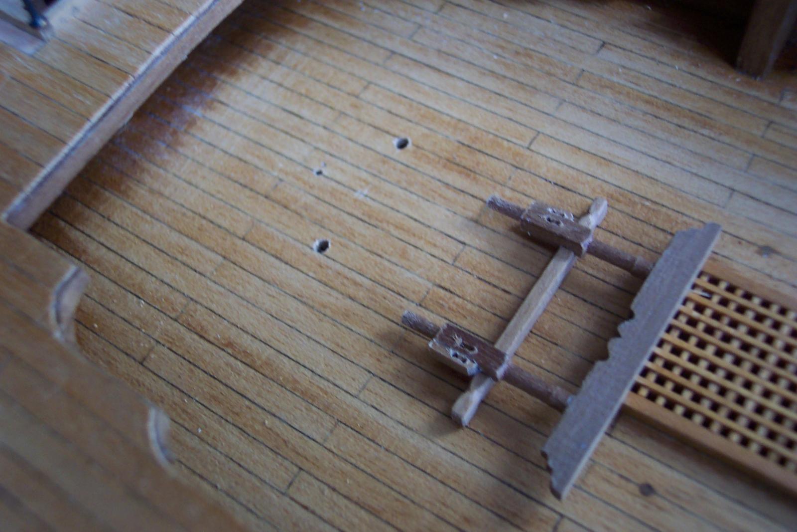
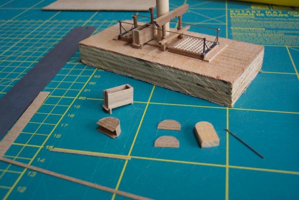
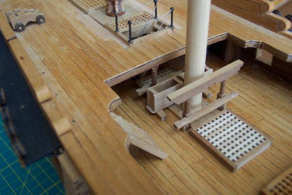
Before going too far I made sure that the sub assembly would line up with the existing parts of the model. To do this I had to drill the 2mm holes in the deck. The photo shews this done. The smaller hole in the deck is a 1mm pilot. There is another in the sub assembly base. I use these to align the sub assembly with the deck. When I am sure that all lines up I will open the pilot holes to take the lower end of the main mast. The parts in place with a 1mm drill bit used to align the sub assembly.