HOLIDAY DONATION DRIVE - SUPPORT MSW - DO YOUR PART TO KEEP THIS GREAT FORUM GOING! (Only 53 donations so far out of 49,000 members - C'mon guys!)
×


ianmajor
-
Posts
784 -
Joined
-
Last visited
Content Type
Profiles
Forums
Gallery
Events
Everything posted by ianmajor
-

Landlubber Mike's technique for furled sails
ianmajor replied to Landlubber Mike's topic in Masting, rigging and sails
I have dropped a PM to Jay to ask him if he would kindly reinstate the images - assuming he has kept copies. Edit update - my PM was bounced. I guess his allocated space is full. -
Mike, It is exciting what these plans reveal. The elevation plan of the stern shows the height and shape of the tiller nicely, along with the wheel behind the mizzen mast. Not to mention the companion way behind the capstan not in front as I did it. How I wish I had bought these plans last year. Nice to see the position of the 12 swivel gun mountings and the position of timberheads. There are several items that have me scratching my head so it is out with the magnifying glass and try to engage brain.
-
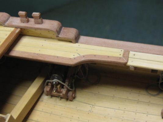
Piet, Your torpedo tube assemble is coming a long very nicely. Fantastic work. I am most impressed in your ability to shape small components with a hand held power tool. I have never managed to get that level of control so always use files. It is probably one of the reasons it takes me so long to make things!
-
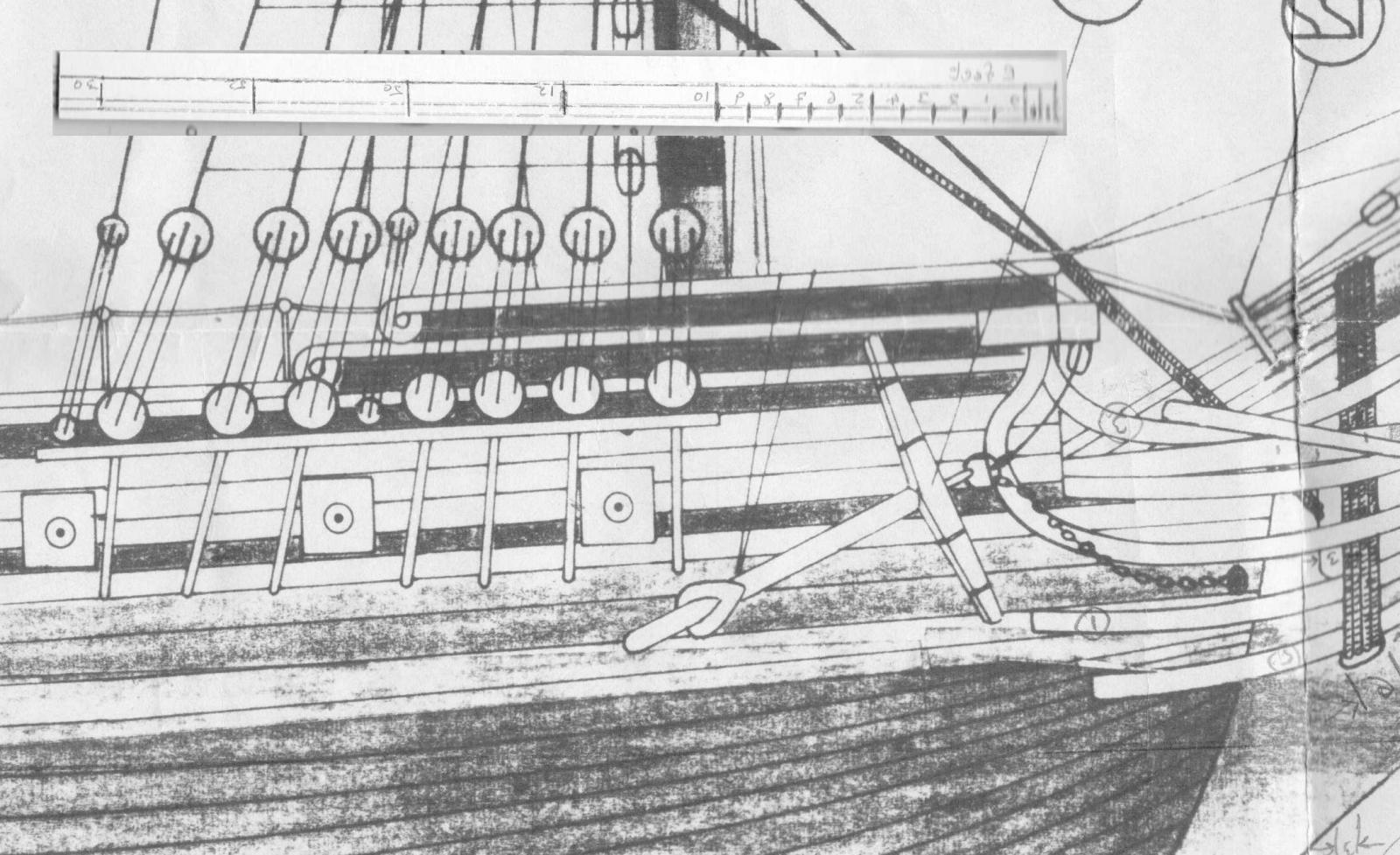
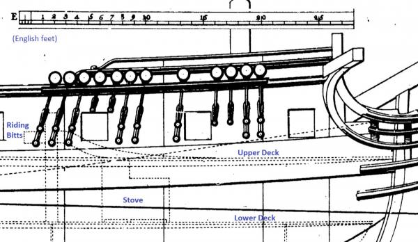
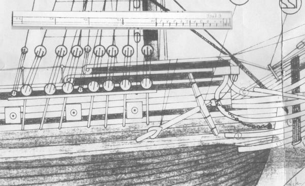
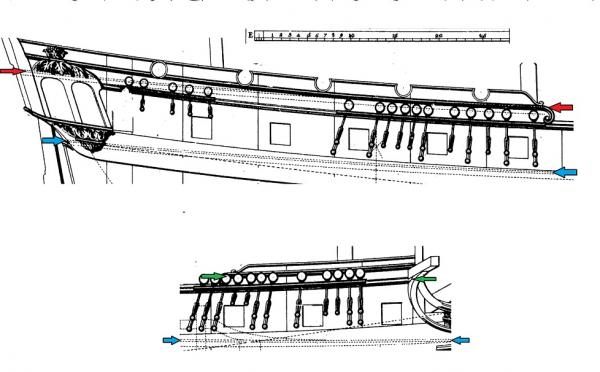
John, Found it. Between the rows of "+"s is the item. ************************************************************************** Below are 2 images, one each of the Corel and Chapman plan with included scale bar. I measured rearwards in scale feet using as a datum the front vertical face of (what is in the model) bulkhead 1. I got the following results (all in feet): --------------------------------------------------------------------------------------------------------- ............................................................. Chapman .... Corel ............................................................. ======== ... ===== Length to leading edge of port 1 ............... 2.5 .............. None ................ do ..................... 2 .............. 11.75 ............13.25 ................ do ..................... 3 .............. 20.5 ............. 22.5 ................ do ..................... 4 .............. 29.75 ........... 31.5 Length to centre line of fore mast .............. 9.0 ............11.6 Length to extreme rear of fore bulwark...... 23.75 ......... 24.75 Length to front of channel ........................ 6.75 ......... 11.0 Length of fore channel ............................ 19.75 ......... 22.25 Distance between centres of ports .............. 9.0 ........... 9.0 ----------------------------------------------------------------------------------------------------------- The distance between the ports matches but everything else on the Corel plan looks to be about 2 scale feet out. Also comparing the position of the fore channel it extends back further in to the waist area than Chapman. So I measured forward from bulkhead 1 and this gave: ----------------------------------------------------------------------------------------------------------- Length to front of hull planking ............. 4.5 ............. 6.75 ------------------------------------------------------------------------------------------------------------ This suggests bulkhead 1 on the Coral plan is too far back by a scale 2.25 ft. (about 9mm). That would be a big change. However, the foremast could be easily moved forward by 2 scale feet (about 8mm) which would pull the fore channels with it to clear the waist area. The foredeck is very cramped behind the foremast so this move would help improve that. This could make the area look too small in front of the fore mast though. ++++++++++++++++++++++++++++++++++++++++++++++++++++++++++++++++++++++++ Hope this makes sense. I am off for a week now but if anything is not clear I am sure Mike will advise. (Edit to correct images)
-
John, I am going to offer a view on the bowsprit that is totally unhelpful! I believe the bowsprit as per Corel and Chapman are more or less in the same position. (What?!!!) The difference is in the location of that first bulkhead. If you measure up the Corel plan versus the Chapman plan, Corel has it further back (it really cramps the foredeck). If you take your diagram 1 and draw the bulk head a couple of scale feet further forward you will end up with diagram 2(ish). In one of my discussions with Mike I put up a set of dimensions around this bulkhead - but I'm blowed if I can remember where I put them. I think the best course is to aim for the Corel alingment or else the bowsprit will probably sit too high.
-
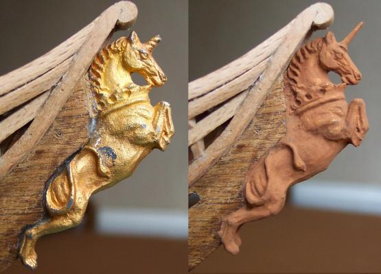
Mike, I will try some washes. Admitedly it has gone from peeling guild and corrosion look to a bit of plastic style.
-
In parallel with the construction work I am producing a belaying schedule. I need to do this now so that when I return to the deck furniture I know what rails, timberheads etc I need to add. The approach I am taking is to make a schedule from Lees p170 for the 1719 20 gun ship (being close in size to the Unicorn). Then to apply the rigging changes (Lees p158) that occured between 1719 and 1748 to (hopefully) get the rigging as the Unicorn was when it first sailed. I have also noted the changes up to 1771 to cover the rigging during its lifetime. It has thrown up some interesting points such as no slings before 1773. One item has disappointed me. The entry that says "1745 - introduction of gaffs on small ships". This knocks my idea of a lateen rigged mizen on the head - I thought it would look really good! Another interesting point is racks for pins. The models contemporary to Unicorn do not have pin racks so I am not using these. However, an entry for 1745 changes says "belaying pins used on racks on the shrouds of small ships". Lees 1719 deck layout shows pin racks in the mizen shrouds and timber heads on the mizen rail (6 per side) with a comment that suggest one or other would be used. Now assuming Unicorn was classed as a small ship I will have to work out how to firmly attach a rack to the mizzen shrouds. Anybody any thoughts on this?
-
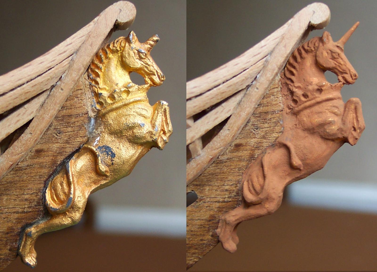
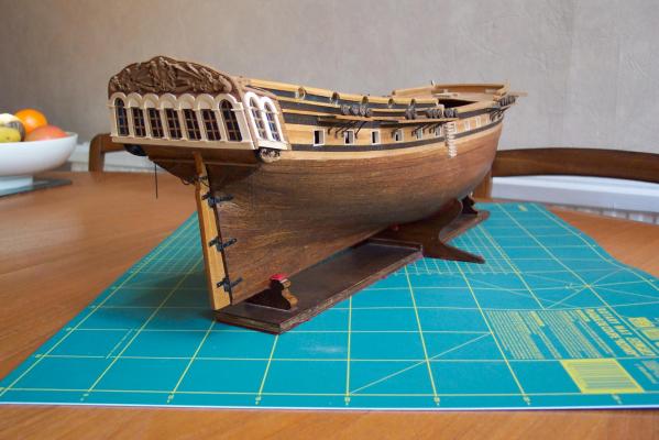
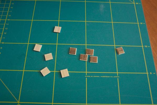
Going with the "boxwood" look the nearest paint that I had was Humbrol M62 which I believe is called leather. The matt finish gives the right effect but I would probably have been better using gloss paint with a matt varnish. The thinned and fettled transom casting was painted and refitted. I also painted the castings on the galleries to make them less garish. I think it looks much better. I am banking on the lime wood toning down in time to match the lime along the gun ports. It sticks out somewhat at the moment. It was also time to give the Unicorn a full horn. I turned a complete replacement from brass. It is 1.8mm diameter at the base and 7mm long with a 7 degree taper. I included a 1.6mm diameter parallel part on the base for fixing. I amputated the stump using a fine bladed piercing saw then drilled a 1.6mm hole in the Unicorn's head. The casting is white metal which has a nasty habit of binding on to small bits so that they won't go in or come out. This risks breaking some of the bit off in the hole which makes life very difficult. So I lubricate the bits well for white metal. The best lubricant - good old fashioned spit. The new horn was glued in and for the first time in 40 years it looked the part. I now have to make sure I don't impale myself on it. There follows a before and after shot, the paint job needs a bit of correction. The black marks in the before shot is corrosion. White metal has the habit of disintegrating into dust after a period of time (I have seen precious ancient railway locomotive models crumble - very sad.) A couple of items to do before returning to the waist. I am going to fit fenders on the side of the hull and lids on the rear three and first two gun ports. I need to make some hinges on the lids, no problem, but I also need to decide how to mount them securely. The lids them selves are one layer of lime strip and one layer of mahogany strip with their grain at right angles to each other.
-
Mike, BTW I am making my way through a rigging schedule for Unicorn (I will let you have a copy for comment, correction,use..whatever ). The approach I am using is to take the belaying plan of a 20 gun ship of 1719 from Lees (page 170) then applying the changes to rigging that occurred between 1719 and 1748 to get an as built view, then noting the changes from 1749 to 1771 to get a view of how the rigging may have looked during its time. In doing this I came across the entry: "1745 - Introduction of Gaffs on the mizen sail of small ships." So much for the lateen rigged mizen on Unicorn. Shame - I thought that it would look really good. No boom, though, until 1793.
-
Mike, To answer the "machine screws" conundrum have a look at http://en.wikipedia.org/wiki/Screw . It has descriptions of different types of screws, bolts, heads and (some but not all) thread types plus links to some standards pages. As it states there is no universally accepted definition of the difference between the types of fasteners known as screws and bolts! So it gives the (US) Machinery's Handbook definition viz:- "A bolt is an externally threaded fastener designed for insertion through holes in assembled parts, and is normally intended to be tightened or released by torquing a nut. A screw is an externally threaded fastener capable of being inserted into holes in assembled parts, of mating with a preformed internal thread or forming its own thread, and of being tightened or released by torquing the head. An externally threaded fastener which is prevented from being turned during assembly and which can be tightened or released only by torquing a nut is a bolt. (Example: round head bolts, track bolts, plow bolts.) An externally threaded fastener that has thread form which prohibits assembly with a nut having a straight thread of multiple pitch length is a screw. (Example: wood screws, tapping screws.)" It is worth noting the photos that show the first turn of thread on bolts is relieved. This gives a tidy start to the thread and helps to thread the bolt in the tapped hole/nut.
-
Mike, The hull is looking very good. As you say time spent at this stage is hugely rewarded at later stages of the build. I await with interest your decision on the Lyme/Unicorn question. Whichever way, we will see a far more accurate model emerging than the basic kit provides.
-
Freek, I can't wait to see it in action. It looks great.
-
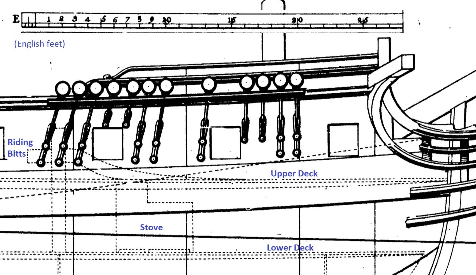
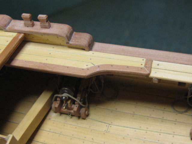
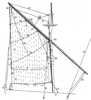
John, I have taken a couple of extracts from the Chapman diagram along with the English feet (E) scale bar (he also has French (F) and Stockholm (S) feet scale bars ). I have marked the quarter deck level with red arrows, the foredeck with green and the upper deck levels with blue arrows. The quarter deck level is clearly marked on the plan but the fore deck level isn't. Using the scale bar I measured the distance between decks as 7ft 6inches on this diagram. As you say 1:75 scale is 4.064mm to the foot so this gives a scale distance of 30.5mm. Now on my Unicorn my deck height is 26mm so if I were to be adding a false deck this would be a lift of 4.5mm. From the links that Mike supplied you will see that our discussions pointed to the fact that the Corel plan has the decks sweeping upwards towards the rear whereas the Chapman plan shows them remaining fairly level. So - IMHO - the false deck would be about 4 to 5mm above the original deck at the leading edge dropping to the same level at the rear. Another point in our discussions is that you will see that the Chapman plan has only solid bulwarks on the quarter deck. Now if you measure the height of the bulwark at the forward end it is only about 2ft high. So almost certainly there was an open rail above this. The height of this rail above the bulwark would decrease towards the rear. The supports for this rail would also have rigging mountings for any guns on the quarter deck. For the step up from the waist I think this photo shows what to aim for. I borrowed it from Dan Vadas' Vulture log (I hope he doesn't mind ) The detail on how he made his gangway can be see here http://modelshipworld.com/index.php?/topic/230-hms-vulture-by-dan-vadas-1776-148-scale-16-gun-swan-class-sloop-from-tffm-plans/?p=135946 His full log starts here http://modelshipworld.com/index.php?/topic/230-hms-vulture-by-dan-vadas-1776-148-scale-16-gun-swan-class-sloop-from-tffm-plans/ The problem with viewing Dan's log is that I look at his work, then my efforts and then weep.
-
Ian, Found a few links on this forum which may help http://modelshipworld.com/index.php?/topic/5479-which-lathe-to-buy/ http://modelshipworld.com/index.php?/topic/4925-proxxon-fd150e-metal-lathe-review/ http://modelshipworld.com/index.php?/topic/1242-cool-tool-lathe-unimat-moved-by-admin/ In the downloads section of this forum there are some good articles in the tools and materials section. A particularly good one is: http://modelshipworldforum.com/resources/materials_and_tools/LatheWork1.pdf . It is by Eric Tilley and contains some very helpful info - including DO's and DO'NTs. Well worth reading for anyone new to lathes. When I first started with lathes I bought myself a book titled Introducing the Lathe by Stan Bray. It cost £5 and still sits next to my workbench.
-
Ian, When pricing the lathe up you need to take in to account that the lathe (probably) not come with any tools. I think there is a least one other thread on this forum that discusses lathes. I will try to ID it/them.
-
Now if you doooo want to change the title, then I believe it is go to entry one and hit edit.............
-
IR3, Thanks. That is some model! I look forward to the next installment.
-
IR3, This a beautiful neat build. I am struggling to visualize the size of the model. I can get some idea of the compartment sizes from the size of the electronic components but not the over all size. Your thought process in fixing the problems is also very interesting. Keep up the good work (when the TMAX returns).
-
Mike, Hum well spotted - just had another look at Chapman and it does,'t show an open bulwark (Lyme does). Doh. I think there should be an open rail there - he has left it off IMHO. My reason for thinking this is that if you follow the quarter deck line to the foremost circular port then measure from the deck to the top of the bulwark shown, I make it 2ft tall. At that height we would have the risk of the officers falling over board. The foremost circular ports opening to free space is a bit unlikely as well.
-
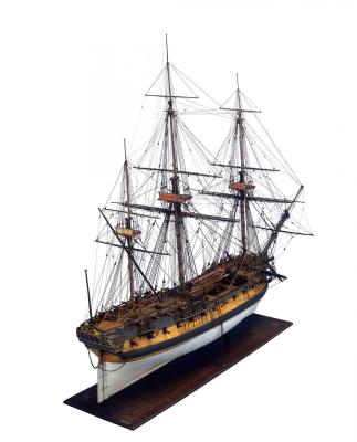
Mike, Just had a look around a few models. The NMM held model of Lowestoft has the open bulwark all around the quarter deck. You can just make it out if the blow the attached picture up a bit.
-
Mike, Both Lyme class frigates had open bulwarks around the quarter deck, these extended down both sides and around the rear. The port holes are shown as complete circles but if you look at the stump of the mizzen mast it should show below the rail (it certainly does on the Chapman plans) which indicates an open bulwark.
-
Mike, I think another item on Unicorn/Lyme that would give variety from your Pegasus is the mizzen mast. During the period of the Lyme class the mizzen was lateen rigged. However if I understand correctly from Lees the sail on the mizzen yard was laced to the mizzen mast. Thus ships in the Lyme period were a half way house between the true lateen rigging and the later gaff based versions. I don't know where I found this photo - I think it was on MSW 1 - but it illustrates what I mean.
-
Mike, I like the idea. When I saw the contemporary plans available for Lyme I did think "If I was starting again I might be tempted to build the Lyme". I believe the Unicorn was just about unique. The later developments of the frigates seem to have been based primarily on the Lyme. This makes Unicorn an interesting ship to model - the significance of this would be lost on most observers I fear. However on the other side of the coin there are plenty of models Unicorn but I have not seen many (any?) of the Lyme. So this makes for a unique model. It would certainly overcome the problem of the first bulkhead being too far back! The Lyme diagrams are better than the Chapman ones, particularly around the layout of the upper deck. If you decide to go that way I think it could be an exciting project. Apart from the beakhead versus round bow the main external differences noted are: 1) the galleries on Unicorn have two windows each side, Lyme has three 2) Lyme has an extra pair of round ports on the quarter deck than Unicorn. Getting to see the higher detail from full size copies of the actual plans may reveal more items of change. If you decide to get a set of Lyme plans let me know the reference numbers and I will send for a set as well. I will be able to compare notes with you (including how to frame them and hang them on the wall )
-
Mike, I would have been tempted to convert to the Lyme but the Unicorn was pretty well unique which makes makes for interest. I better not put any more Unicorn thoughts here since this is supposed to be Pegasus!