HOLIDAY DONATION DRIVE - SUPPORT MSW - DO YOUR PART TO KEEP THIS GREAT FORUM GOING! (Only 53 donations so far out of 49,000 members - C'mon guys!)
×


ianmajor
-
Posts
784 -
Joined
-
Last visited
Content Type
Profiles
Forums
Gallery
Events
Everything posted by ianmajor
-
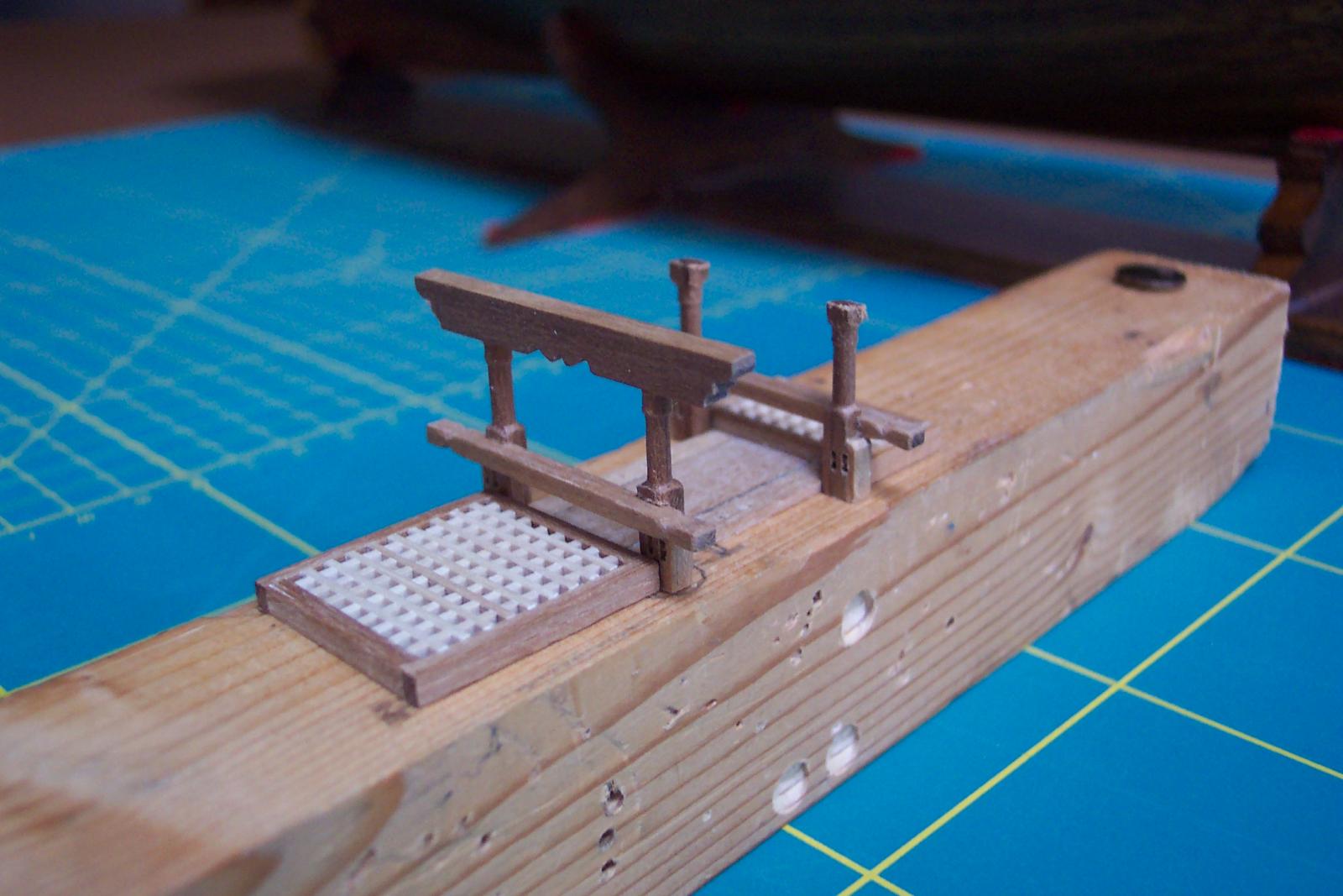
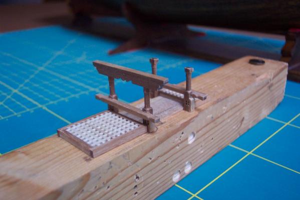
 Thanks all for the likes. BE thanks for the compliment. I am starting preparations for making the masts so I have been looking at your log - particularly relating to Steel. He and Corel don't seem to match. I know which I believe! Well I started work in earnest on the cluster of deck furniture around the main mast. I am assembling this group as a complete sub unit. The first photo shews the components I made for the main topsail sheet bits, main jeer bits, and the gallows crosspiece. My last delivery of walnut was rather grainy and much prone to splitting compared with previous lots. So before turning and milling the uprights I gave the pieces a coat of varnish which seemed to hold it together. Where they are to be glued the machining removed the coat of varnish - so that was OK. My last delivery also had a piece of 5 x 5mm walnut strip that was badly split over about a third of its length. I cut a section of the split part off and ran it through my milling contraption (see previous part of log). This gave me a nice sound piece of 3 x 5 for the crosspiece. I turned the main topsail sheet bit uprights with 2mm diameter extensions top and bottom. These fit in to 2mm diameter holes in the deck and the underside of the crosspiece. For assembling the sub unit I used a jig - simply a bit of wood with holes drilled in the appropriate places. The next photo shews the start of the assembly process. As more parts are made and added I will use this to ensure everything fits together before committing it to the main model.
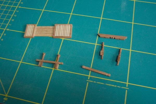
-
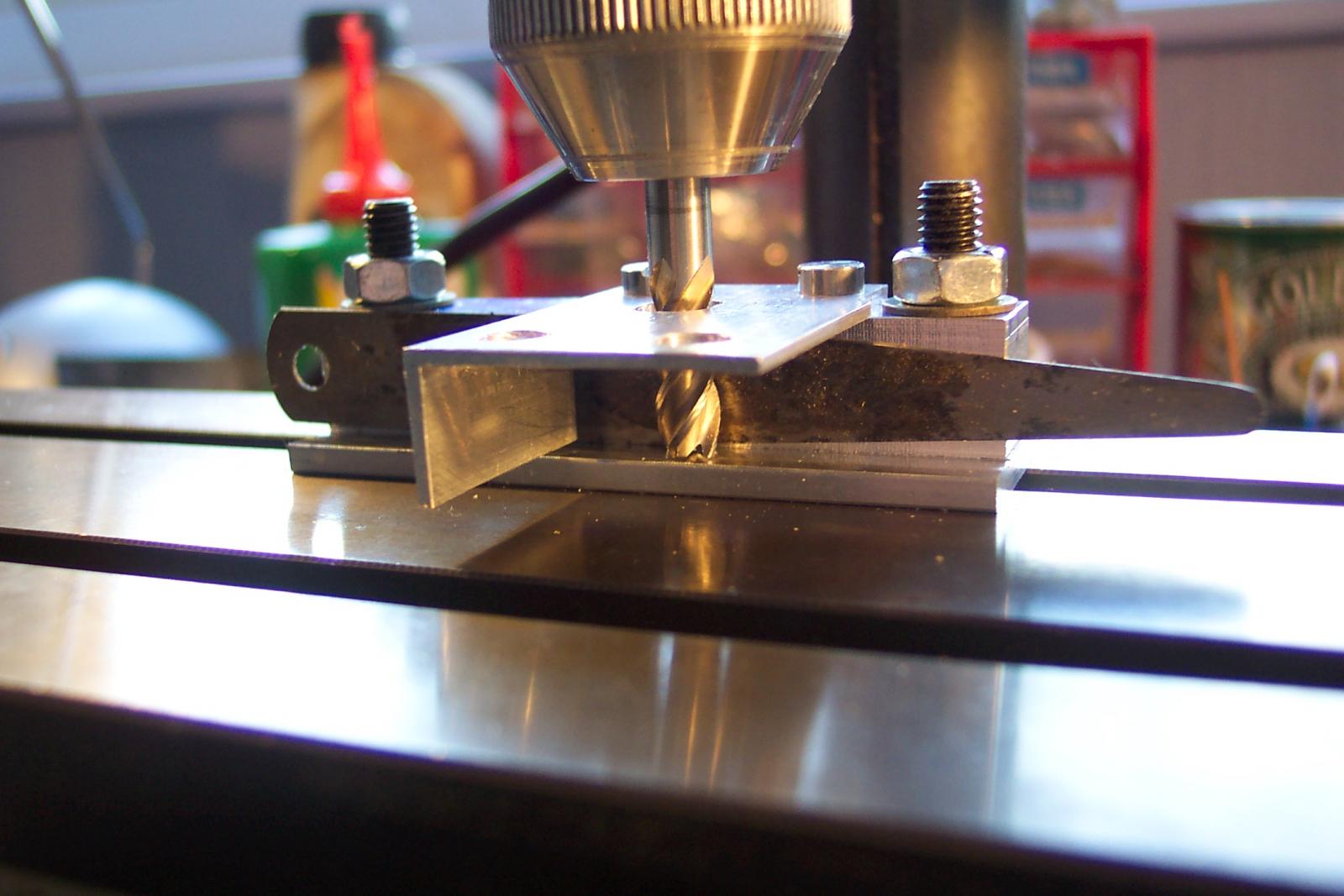
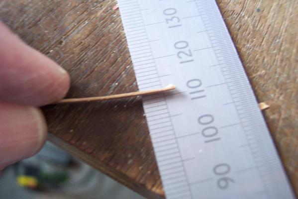
Then I fed some scrap bits of 1mm wallnut in to the device. I experimented with various settings. First I had the bit running at high speed. This grabbed the wood and fired it across the workshop. Failure. Then I used a much lower speed. This was much better. I still had to grasp the wood firmly to stop it shooting through the device but I ended up with some 0.5mm thick wood. Some wood of this thickness produced this way was used in flue lining. After more experimentation I decided the best approach was to to reduce the thickness of the wood by small amounts using several passes - adjust the device to reduce the gap between each pass. It was less violent, Produced smoother results and reduced the risk of tearing the wood. It is not ideal but it allows me, safely, to plane wood up to 10mm wide down to 0.5mm (or less thick). Modeler12 has come up with some interesting mill attachments (see for example here). They are considerably better constructed than mine!

-
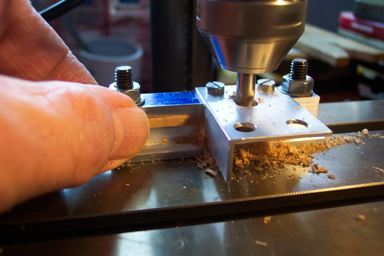
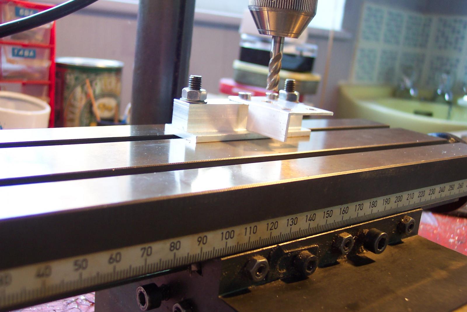
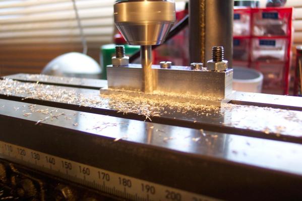
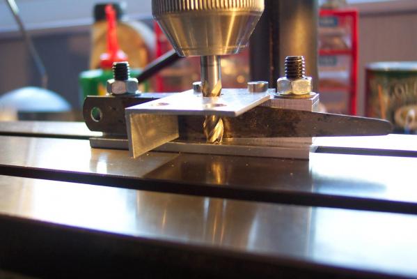
Most of the measurements on this attachment can be plus or minus a hammer head's width. The exception is the face of the block that will be next to the mill bit when wood is being planed. It is important that the side of the mill bit is vertically parallel to the side of the block else the result is wood with a tapered cross section. So to ensure this I removed the guard, fitted the block and base to the mill table and took a skim off the face of the block. Even after the attachment is removed and refitted the mill bit will remain parallel to the block's face. Now it was time to try it out. I refitted the guard and lined up the mill bit with the centre of the oval hole then locked the 'X' (side to side) co-ordinate control. Then I lowered the bit until it was just short of the base and locked the 'Z' (vertical) control. Using the 'Y' co-ordinate control I moved the mill bit towards the block and used a 0.5mm feeler gauge to set the gap.

-
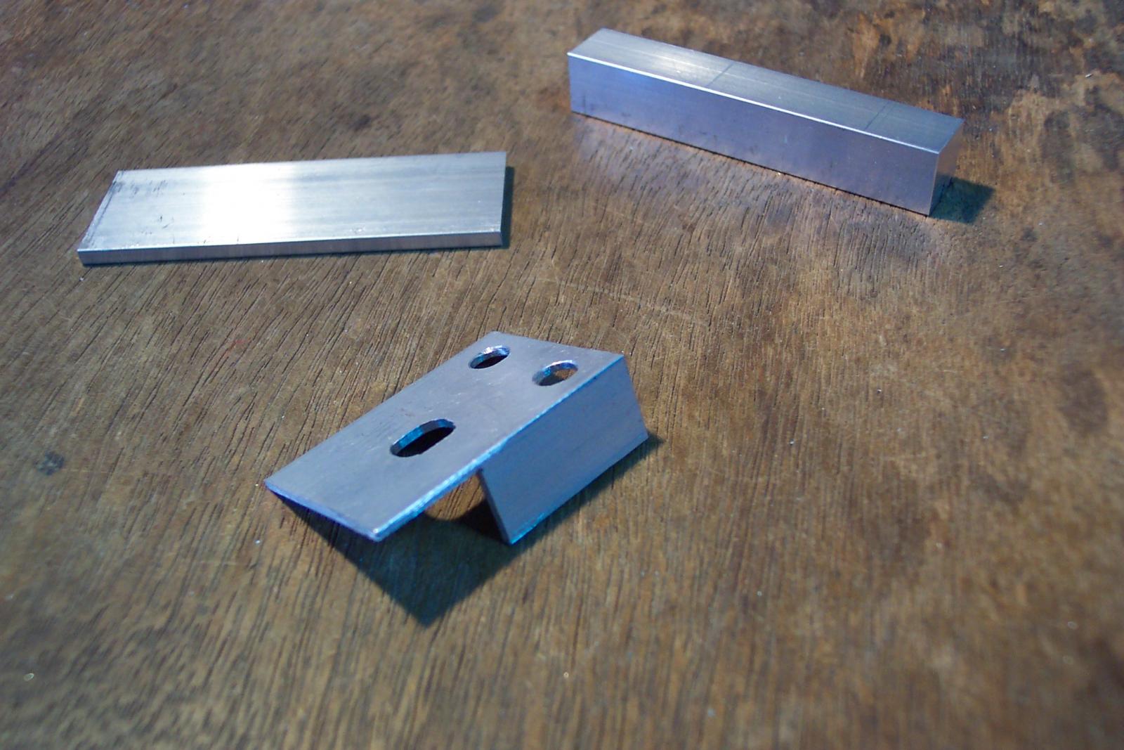
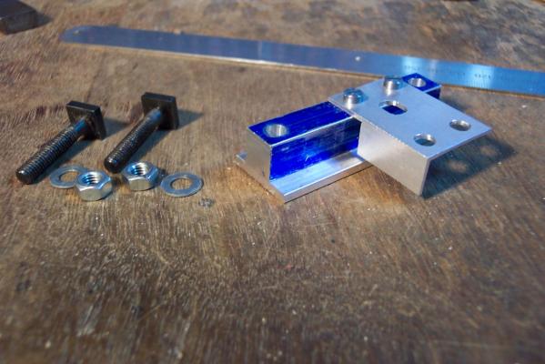
Hello John, Mike and ZyXuz . Thanks for the comments. A thanks all for the likes. I don't think I am brave. My wife thinks that I am certifiable. When I lined the hole in the deck through which the flue passes I decided to use 0.5mm thick walnut. The thinnest walnut that I could get was 1.2mm. I will require 0.5mm material when I make the bodies of the pumps, the binnacle and also planking for ship's boat(s). I don't possess one of those nice wood planing machines and can't justify the cost of getting one. Also my attempts to use a hand plane produce inconsistent results. So I knocked up an attachment out of some bits of aluminium to fit on my micro miller. The principle is to have a block of aluminium clamped to the mill table, bring the milling bit up to and alongside the block, then to feed the wood through the gap. The width of the gap between the block and the bit determining the resultant thickness of the wood. Simple but rather dangerous. My milling bits have steep spiral side cutting edges designed for metal. They tend to grab the wood and pull it through sharply - which could pull my fingers in with it. Nasty. So I produced something slightly more complex with a safety guard on it. I started with three bits of aluminium. 1) A block with a square cross section to act as the fence. 2) A wider piece of aluminium strip to act a as a base and to protect the miller table. 3) A piece of aluminium angle to act as a finger guard. The angle in the photo has one side cut back. The wood will feed through here. There is also an oval hole in the middle through which the milling bit will pass. It is oval to allow the bit to be moved towards or away from the fence to give different thicknesses of wood. The other two holes are decoration only (I reused a piece of angle which already had the holes in it). Next I clamped the base under the block and drilled clearance holes through each end to take a pair of T bolts. Then I clamped the angle on top and drilled 2 holes right through. These were tapping size (in my case for 4BA thread). I removed the angle and opened the two holes in it to clearance size. The block and the base were then threaded with a tap. The three parts could then bolted together.

-
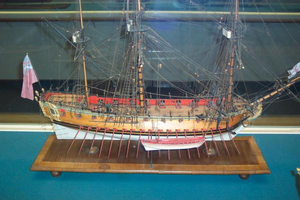
Hamilton, On my recent visit to the NMM I photographed the model of the ship ship with sweeps. I was intrigued that it is displayed with one of the ship's boats resting on the sweeps. I could imagine the crew manning those sweeps complaining about the extra weight and the crew in the boat wondering why they were going up and down and backwards and forwards! The boat also has the lifting gear from it up to the fore and main yards.
-
Hum.....I am not so sure about that. Mistakes tend not to scale down. If anything they stick out like a sore thumb on smaller scale models. The quality of your model is purely down to your excellent skill - not hard to see mistakes.
-
Piet, Fabulous work - and ever more great information emerging on subs in your log. Not only did I not consider that subs might have had dinghies but that they might trap air when submerged. All obvious really - but only when someone points it out! I can't wait for the next installment.
-
I have also reinstated the missing images in this post (about 20 of them).
-
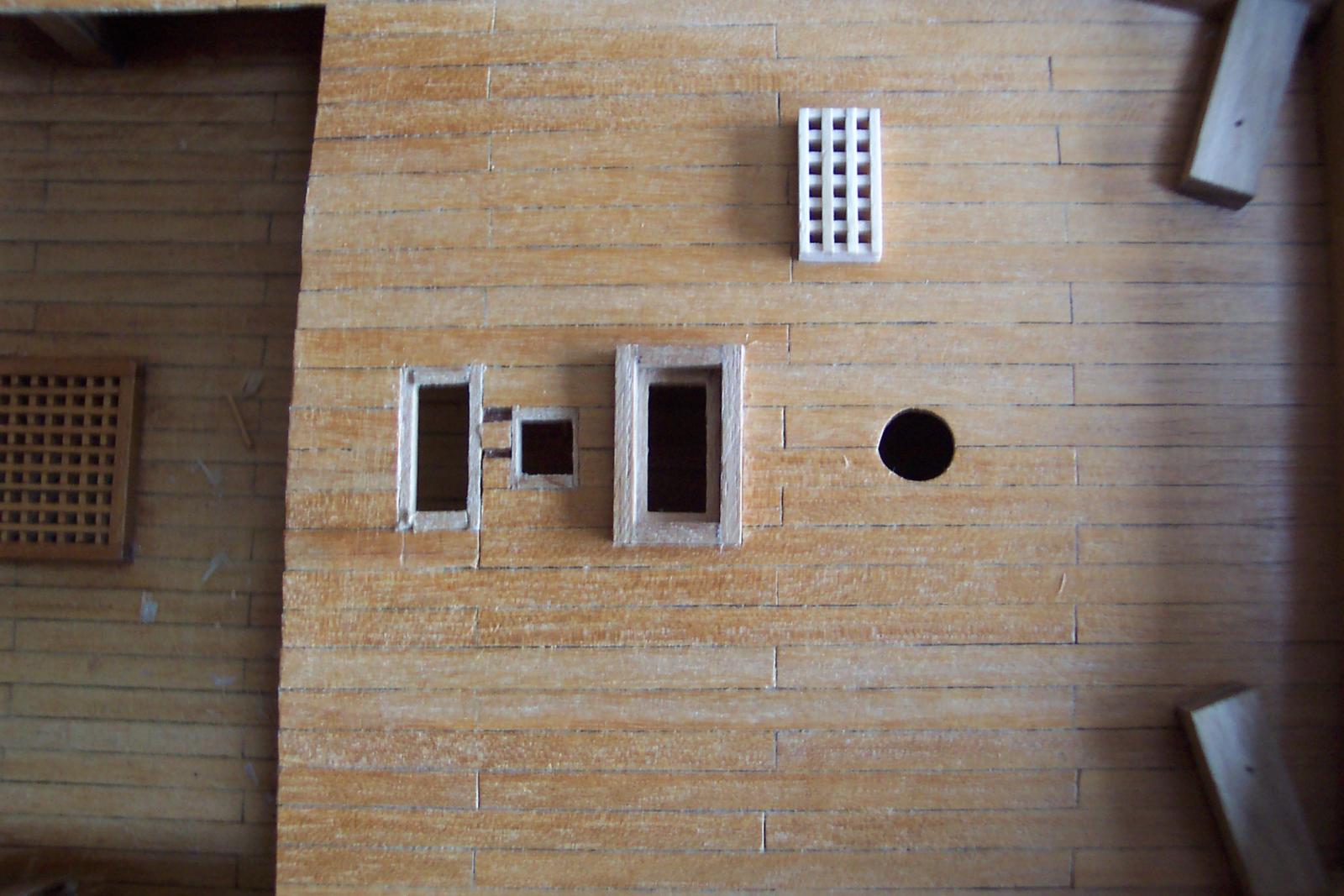
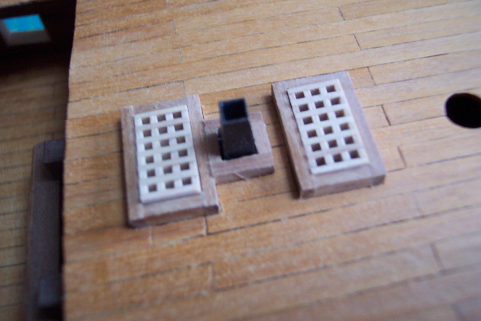
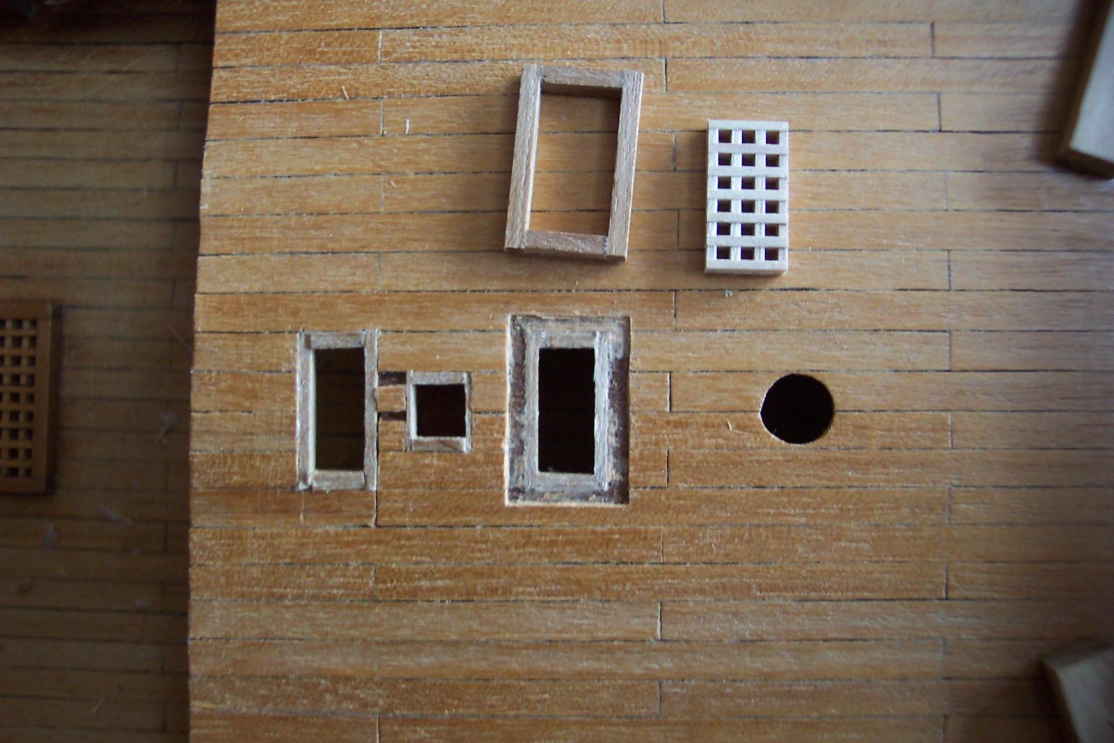
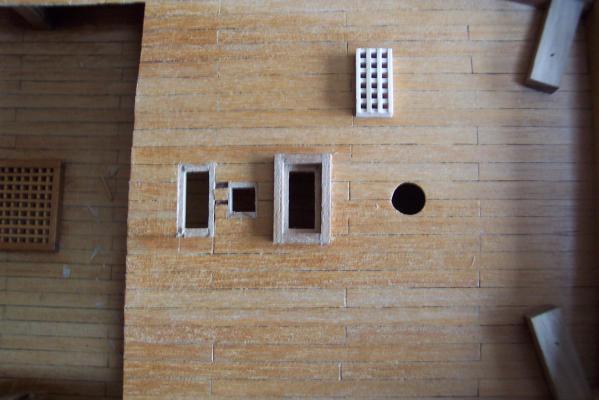
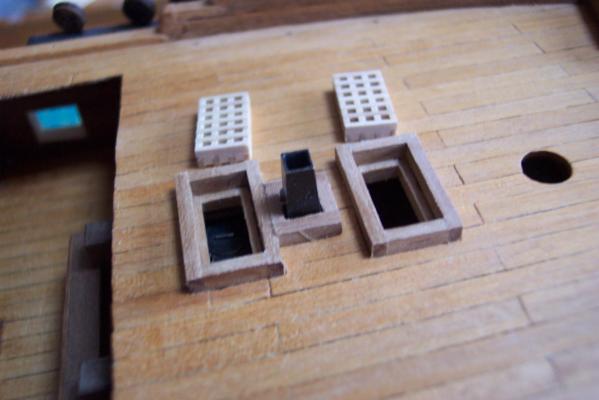
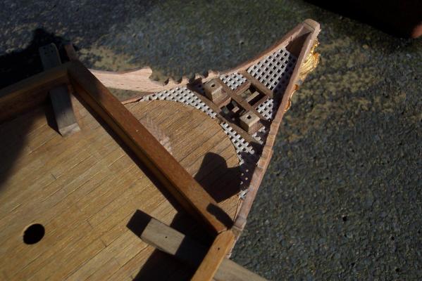
The frames were then fitted around the lined holes. Once the frames were glued in to place I did a test fitting of the stove and its flue. Then the gratings were tried for fit. The gratings should be curved to match the camber of the deck but I left them flat to match the existing gratings. The frames are also rather too thick in cross section but again this matches the existing fittings. Then I had a Homer moment. I looked at Dan Vadas' Vulture and realised the lip supporting the gratings should only go across the ends not down the sides. I should have used thinner lining down the sides. Doh!

-
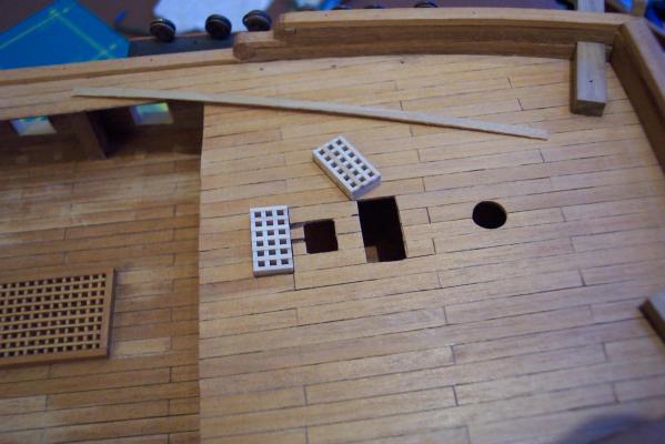
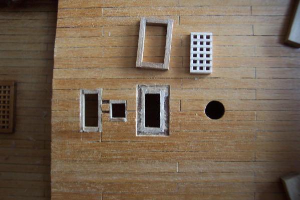
Hamilton and BE thanks for the comments, and thanks to the others for the likes. Whenever I walk down into the village I pass the sign outside our local "lifestyle boutique". For some reason it always makes me think of model ship building. Well I managed to finish the gratings on the foredeck. I wanted them to be removable so that the stove colud be seen. The technique I used had to be such that my poor woodworking skills could cope. So the first step was to make two gratings - making sure that they were both square and the same size so that they could be fitted any way around and be interchangeable. This was quite easy using the Mantua grating. The next step was to cut and file up holes in the foredeck that allowed these gratings to just pass through. Then I lined the holes with 3 x 2mm walnut strip to make a ledge for the gratings to rest on, and also to give the impression that there were beams on the underside of the deck. I also cut and lined the hole for the stove flue to pass through. Next I made frames from 3 x 2mm walnut that were a nice sliding fit around the gratings. To make sure the ends were identical in length I cut 6 pieces slightly over length, glued them together then filed them to size. This also makes it easier to file them square. The parts of the frames were glued together using the gratings as assembly jigs. To fit these I cut the deck planking away around the hole and trimed the top of the lining to allow the frame to sit snugly in to the deck

-
Outside, at the rear of the museum, is a model ship in a bottle which is claimed to be the largest in the world. I couldn't resist adding a photo of it. The sails have pretty patterns on them reminiscent of curtain material! All in all it was a very interesting and useful trip. I thoroughly recommend a visit. It is also one of the most pleasant parts of London as can be seen from the next photo. This was taken from the top of the hill in Greenwich Park near the Observatory. The old Naval College is dead ahead, the NMM is hidden in the trees on the left, the masts of Cutty Sark can be seen above these trees and across the river in the background is the familiar skyline of Canary Wharf. Having been inspired it is now time to get back to some more modelling.


-
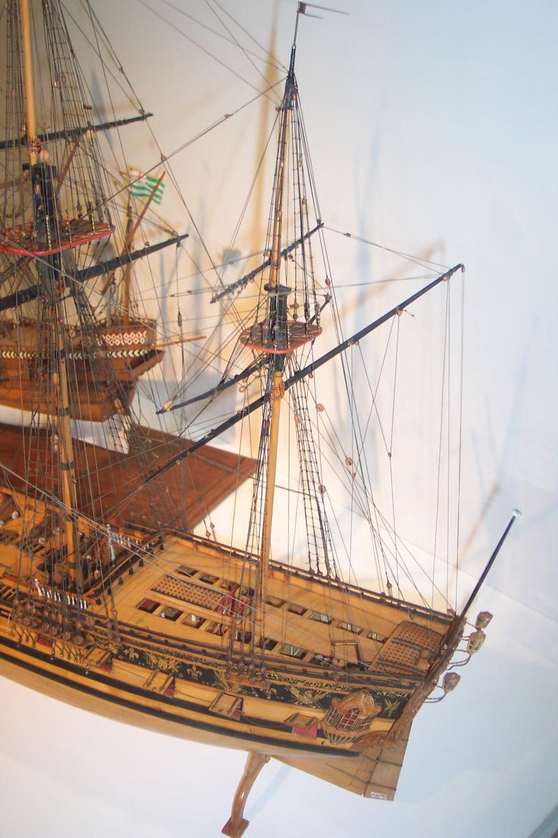
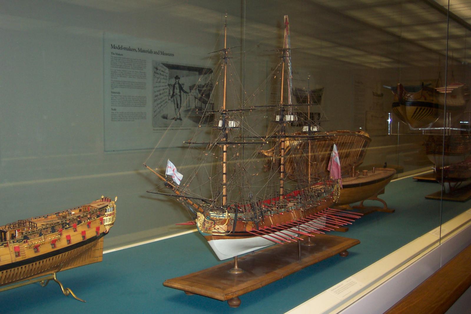
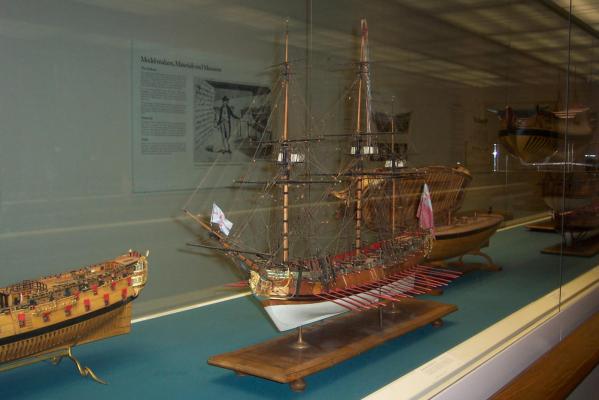
Many thanks for the likes they are most apreciated. Gianni, the main advantage of this extra grating is that it hides some of my poor work around the bow! Well - I am back from an enjoyable trip to the NMM during which time I had no access to the Web. So I will add a slight digression off topic. On arriving I got my first view of the Cutty Sark. My wife and I walked around the adjacent old Naval College then in to the nearby NMM building. Much of our time in the museum was spent looking at the paintings in the "Turner and The Sea" exhibition. After some of the comment on MSW I was not expecting to see many of the old models on display. I was, therefore, pleasantly surprised that there were about 40 sailing ship models to be seen. A few were in the children's section on the top floor of the west wing, the rest were in two large glass cases in the next room. I took a few photos of them - in particular I was interested in the early 18th century rigging. All the models from this period had lateen rigged mizzen masts - this conforms to the way I wish to go with the Unicorn. The next photo is one of those that I took and which I will use to guide my rigging efforts. It is of one of the models in the children's section. It shews the mizzen mast of a ship dated 1710. In the background is an English galleon of 1588. I was trying to see how the running rigging was belayed since there are no belaying pin racks to be seen. I need to understand this better before finishing the deck fittings. In some of the models there were belaying pins fitted in to the top rail of the open bulwarks, others the rope was wrapped around the bulwark rail. In some of the models the rigging appeared to be simplified with, for example, rope passing in to a block with it apparently glued in to the block then cut off at this point - presumably the result of a repair at some time. I will have to consult a copy of Lees. I have added a general view of one of the main glass cases.


-
Mike, Well done. You have produced a lovely model. When you begin applying this standard of work to the Unicorn I think I will have to hide mine away!
- 153 replies
-
- 1
-

-
- badger
- caldercraft
- (and 1 more)
-
Daniel, A fine collection of models - and great to see your creations deservedly amongst them.
-
Hello ZyXuz, The blocks that I am referring to are the ones I need for rigging the cannon. The two blocks on the bow are euphemistically known as the seats of leisure. None of this is covered by the Corel kit.
-
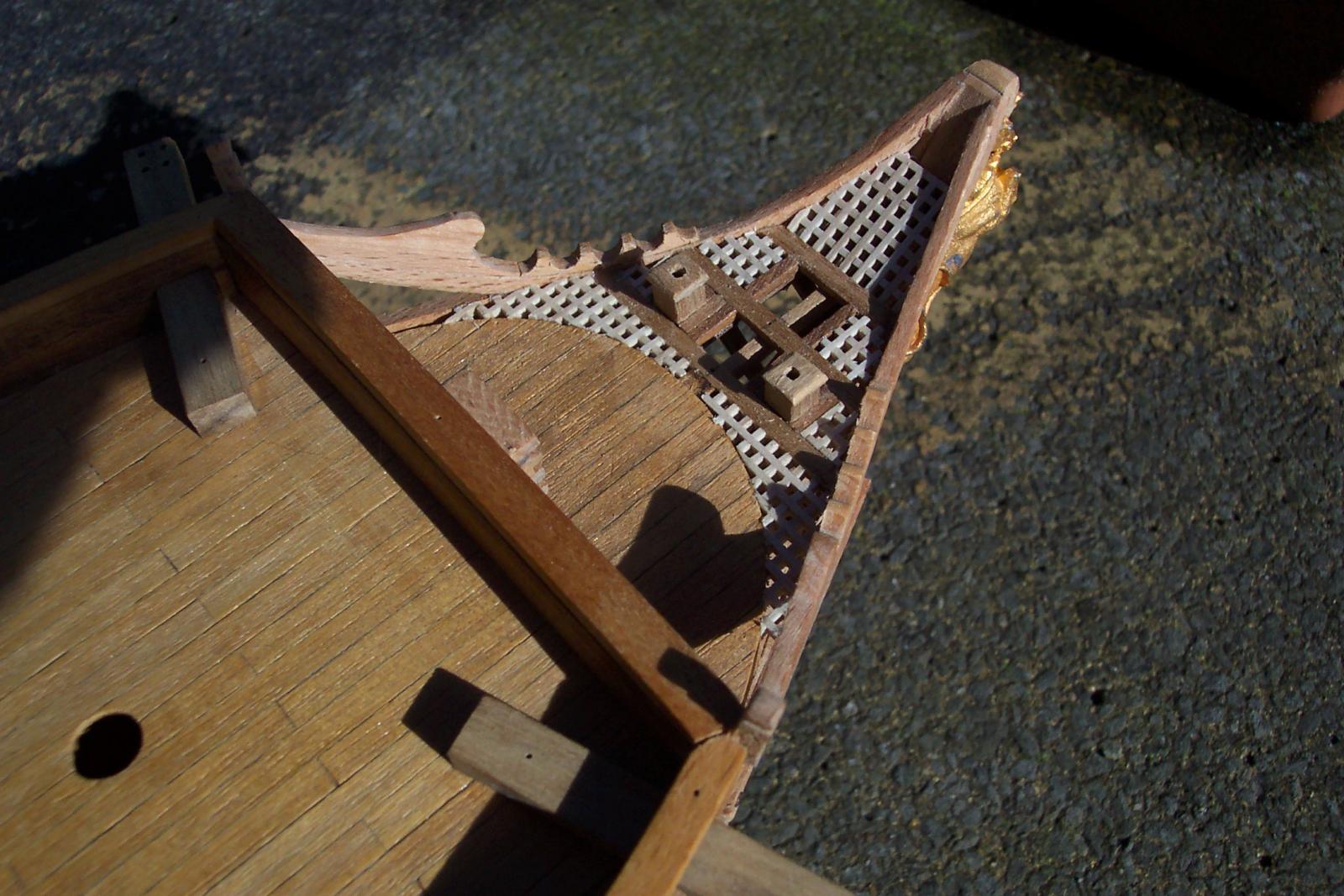
I have been away from the workshop for much of the last 6 weeks so progress has been rather steady. I had intended to start rigging the cannon but discovered I had only ordered sufficient 2mm blocks to do one third of them. So before putting in a fresh order to Cornwall models I decided to get a few other jobs done to see if I needed any other items. My main work was fitting gratings around the bow area of the ship. I had previously ordered some Mantua 1.5mm beech grating for the cluster around the main mast. I had been unable to source the Corel variety. When I received the Mantua gratings I was very pleased with the quality. It is much less fragile than the Corel offering. The question was - did I have enough to do all the gratings including those in the bow? The gratings took a lot of fitting to get them in to place. I don't think the Corel grating would have stayed in one piece with all the sanding and filing that I did. The bow on my Unicorn is distinctly asymmetric so I had to be careful that the lines of the grating didn't accentuate this. I think I managed reasonably well. The foremost grating inclines upwards, which it probably shouldn't, but it does now cover some of the horrors in that area. After the lousy weather of the last 3 months it was nice to have a day of sunshine. So I took a photo of the old tub out in the fresh air. I have ordered the extra 2mm blocks plus some trim to try to improve the area around the stern. First, though, I am away from the workshop again for another week. I will be in the London area and I am taking the opportunity to make my first visit to the NMM. It has an exhibition of Turner paintings on display at the moment - I will get to see the painting of "The Fighting Temeraire" amongst others. Then on my return I hope to make some serious progress on the Unicorn.
-
Ed, Wonderful workmanship coupled to a fascinating description.
-
casting metal parts including cannon
ianmajor replied to rtropp's topic in Metal Work, Soldering and Metal Fittings
Joe, Yes please - a tutorial would be very useful. In the world of model railways resin casting has come on in leaps and bounds in the last few years from "dodgy chocolate block" to highly detailed results. It is now frequently used in high quality kits. -
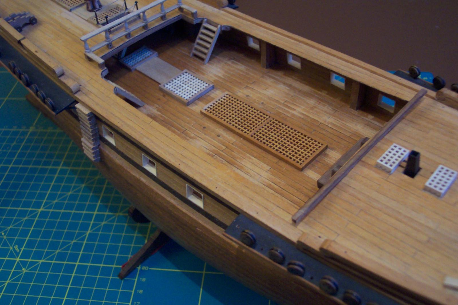
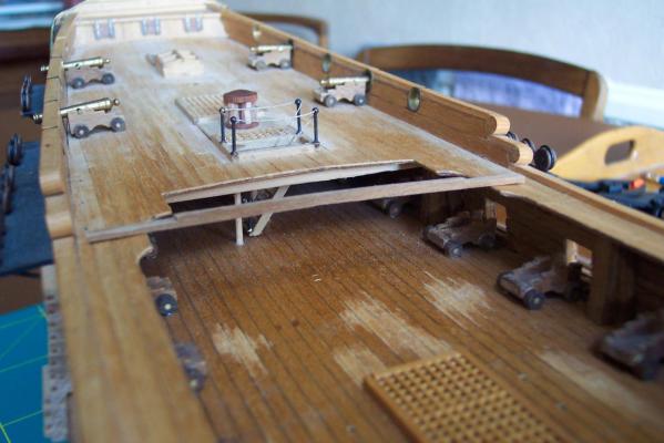
It has been a few weeks since I last did an update. There have been a few (pleasant) family distractions but I have still managed a bit of progress. I used 3mm square walnut to make beams to go under the rear edge of the waist area. The under edge of the deck is chamfered so that the edge of the plywood doesn't shew. This makes the shaping of these beams a little complex. The first photo shews the main beam ready to be fitted. The next photo covers all of the recent progress. The beams are fitted around the rear edge. They actually consist of 9 pieces fitted together. Against these I have placed the two ladders which were made using the jig that I made for the companion way ladder. The gun ports are all now lined to hide the gaps. I increased the size of the ports to allow for the thickness of the lining. I used 0.5mm thick lime. The quarter deck rail is nearly complete. It is not yet permanently fitted. When it is I will add some metal rails on the wings. The cannon have been removed for now. They were in the way. They will be rigged when they are refitted. Below the front of the quarter deck is the beginnings of the chain pump/main mast partners cluster. I am making this as a separate sub unit. I have positioned its base temporarily in place to ensure the cannon rigging does not clash with it. I will cover the building of this unit in more detail as I do it. Along the rear edge of the fore deck is the 3mm square walnut shaped ready to fix under the fore deck once the stove is permanently fixed in place. There are also gratings awaiting their coveing sat in place on the quarterdeck. These are intended to be removable to make the top of the stove visible. Next up will be revarnishing the gun deck. I can then start rigging and fixing the cannon. This won't be for a few weeks because my wife and I are off to the Lake District for a (probably wet) holiday.

-
ROYAL CAROLINE 1749 by Doris - 1:40 - CARD
ianmajor replied to DORIS's topic in - Build logs for subjects built 1501 - 1750
Doris, That is breathtaking. Even where you correct and repair the results are clean and crisp. I remain jealous of your students.- 883 replies
-
- 1
-
-
- royal caroline
- ship of the line
- (and 1 more)
-
ZyXuz, Good to hear from you again. On your stove - if you want an iron stove but don't want to metal bash, have you considered using styrene sheet? It is easy to use, particularly if you use solvent glues. Producing rivet or bolt detail is simple. It produces a good representation of metal work. The down side is that you have to paint it. Alternatively - the Unicorn may well have had one of the old brick hearths. Remco has made a fine one for his Kingfisher. If you haven't seen it have a look starting here . Miniature bricklaying at its best!
-
I think the problem that Anthony has highlighted is a UK supply issue. I have had defective bits from several outlets over the last couple of years. This included boxed sets and packets of same size small bits. I suspect they all came from the same source. I don't know about Anthony's supplier but the bits that I bought were certainly not cheap.
-
Antony, I have also noted a decrease in quality of drill bits over the last couple of years. I buy mine in packets of 10. A recent packet of 0.5mm bits all had the tips ground looking like a ridged roof. I have also had bits where the tip has been ground off centre which result in over size holes. I put it down to the "economic climate" where rejects that would once not get through are now being fobbed off on model makers.
-
Freek, Love the hatch. This sub is coming along beautifully.
-
ROYAL CAROLINE 1749 by Doris - 1:40 - CARD
ianmajor replied to DORIS's topic in - Build logs for subjects built 1501 - 1750
Doris, Your latest work has left me speechless.- 883 replies
-
- 1
-
-
- royal caroline
- ship of the line
- (and 1 more)