HOLIDAY DONATION DRIVE - SUPPORT MSW - DO YOUR PART TO KEEP THIS GREAT FORUM GOING! (Only 53 donations so far out of 49,000 members - C'mon guys!)
×


ianmajor
-
Posts
784 -
Joined
-
Last visited
Content Type
Profiles
Forums
Gallery
Events
Everything posted by ianmajor
-
 Very nice Dafi and very educational. Are you going to turn your attention back to the complete Victory? Looking forward to that.
 -
Dafi, Fascinating work - no doubt I will be trying to copy this in the near future. I noted the black fingers. If ever I get blackened fingers I seem to reinvent the printing press producing nice black fingerprints everywhere (especially where they are not wanted).
-
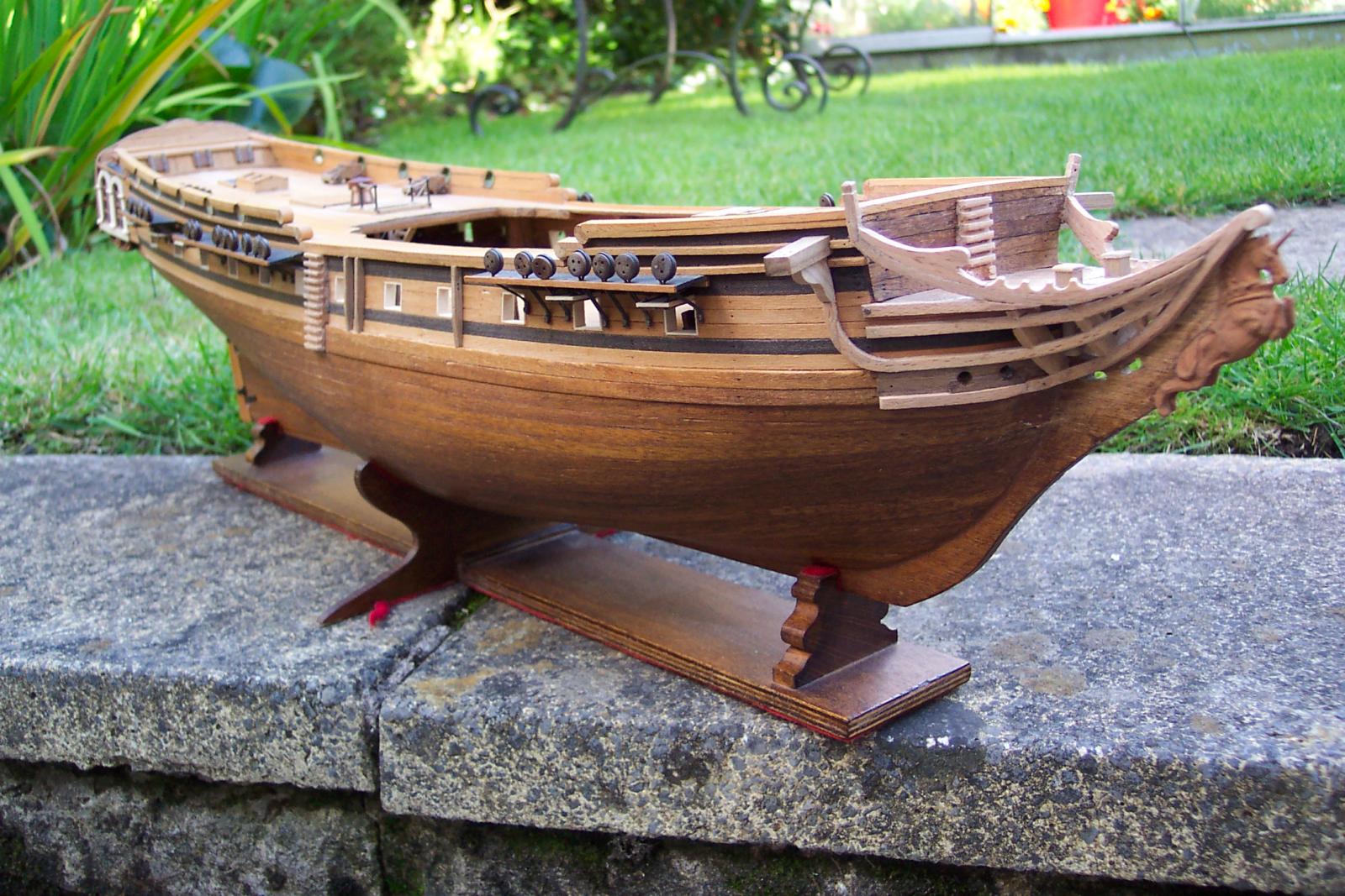
I also added the fenders and chesstrees to the hull in the waist area. Each chesstree was drilled and filed to represent a sheave to take the main tack, plus holes drilled in the hull to feed it through. There is a bulkhead extension inside at this point where a cleat should be so I will be using a stopper knot on the inside of the hull instead of belaying to a cleat. It looks OK. A view along the hull with all of these items in place. It looks almost respectable. That completes the exterior work on the hull for now. I still have some items to add around the stem but I need to produce the bowsprit first to make sure I get them aligned correctly. So now I can't put off the gun rigging any longer.


-
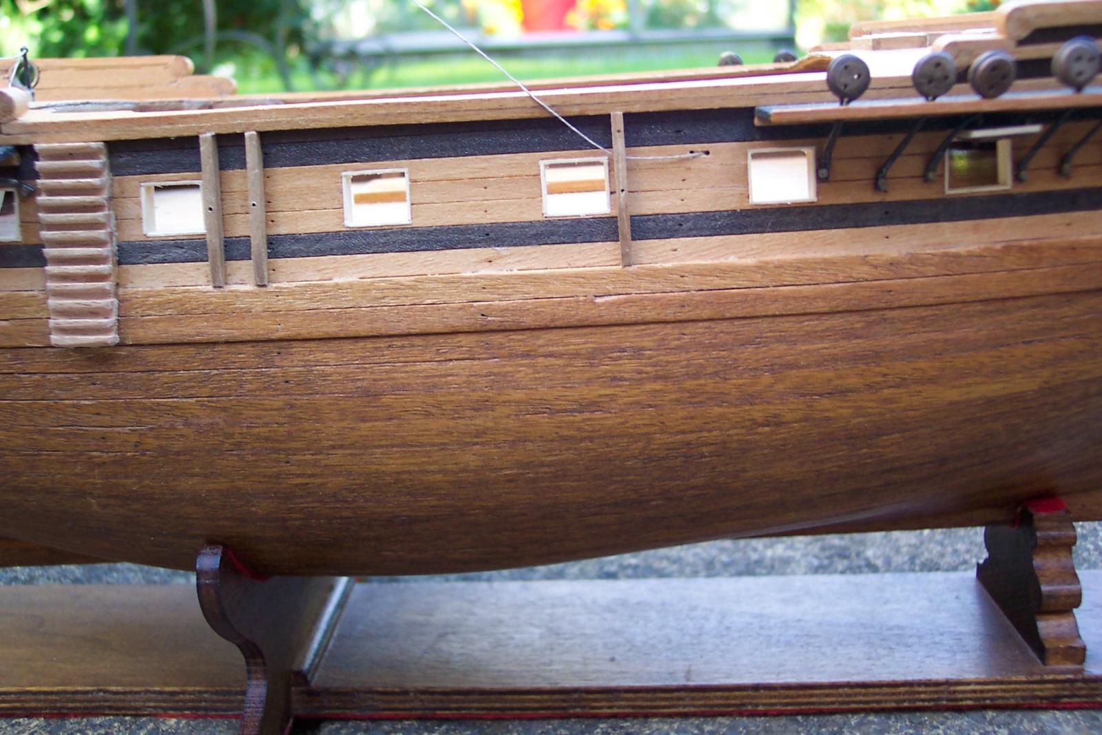
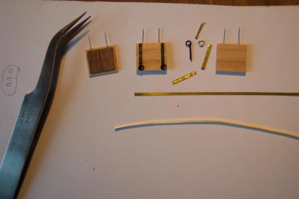
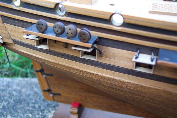
Grant, Thank you for your kind words.Praise from a great modeler such as yourself is fine praise indeed. If I can answer any questions I am always willing to try. Well I have not been totally idle over the last month. I am still working through a rigging schedule which is taking a fair amount of time. I completed the gun port lids. The hinges were made of 1.2mm wide strips of 0.2mm thick brass. I embossed these to represent the bolts plus drilled them to take the rings. The rings were wound from 0.3mm brass wire using a 2mm former. I also produced some split pins to hold them in place. The hinge edge of the lid I drilled to take two short pieces of florist's soft iron wire. These would also go in to corresponding holes drilled in the hull to give some additional support to the lids when glued in place. The wire being soft allows the lid position to be tweaked before the glue set. As per the contemporary models of similar sized ships I produced 5 lids per side being: 2 off to cover the gun ports around the crew/cooking area under the foredeck. 3 off covering the captains cabin, the captains sleeping quarter on the starboard side (an anti-room on the port side) and covering the gun port immediately ahead of the captains quarters. From my discussions with Mike it became apparent that the Corel plans show the channels too low down and I had fitted my channels as per the plans. The spacing of the deadeyes is also not ideal. I was concerned that they would cause me problems in fitting the lids - and so it proved to be. The lids are badly crowded by the channels. The ropes to lift the lids should enter the hull a couple of millimeters higher than I have them, but any higher and they would have fouled the channels. For consistancy I fitted all of these ropes at the same angle including the pair that are clear of the channels. Not good - but looks OK when I take my specs off.

-
Wonderful. It would be nice to see a photo of the proud builder/owner alongside his creation - for scale purposes don't you know.
-
Piet, I think I prefer to view the loaded torpedo launcher from the side - it looks rather scary from head on. Take care of yourself and keep up the great work.
-
Dafi is being very modest in not mentioning his own fine rendition of an anchor buoy starting at http://modelshipworld.com/index.php/topic/76-hms-victory-by-dafi-to-victory-and-beyond/?p=215380 .
-
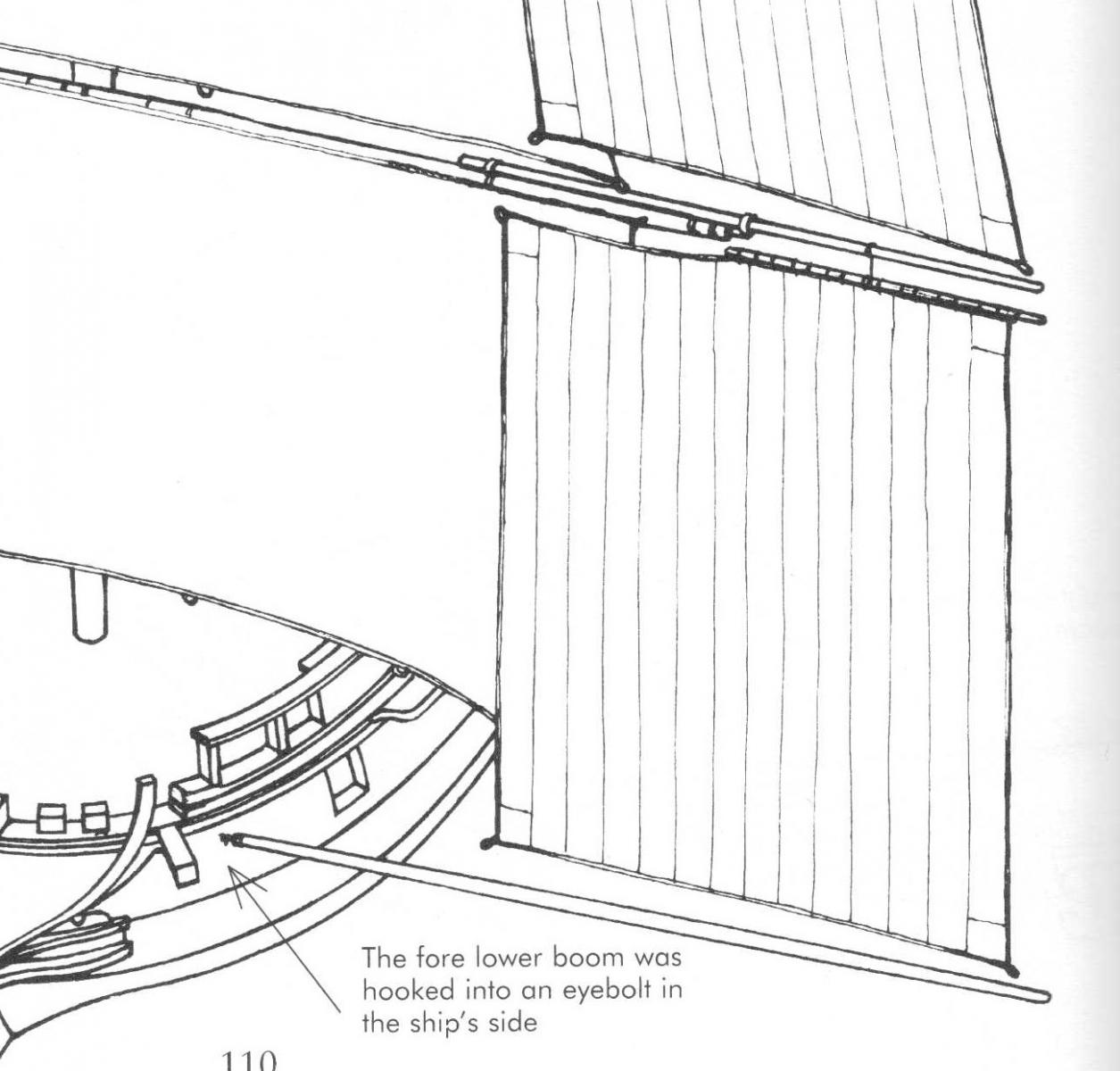
Captain Dafi (or should that be Sir now!), An interesting point you make about the fore lower studding boom. It did occur to me that there could be a conflict twixt boom and anchor if the boom was attached to the fore channel. The main lower boom irons on the main channel are nicely illustrated in Dan Vadas' Vulture log at http://modelshipworld.com/index.php/topic/230-hms-vulture-by-dan-vadas-1776-148-scale-16-gun-swan-class-sloop-from-tffm-plans/?p=159222 The only info on the fore lower booms attachment that I have seen is in Petersson page 110. The boom is hooked in to an eye in the hull rather than on the fore channel. This mounting point is well forward of the foremast so I guess when deployed the boom would point rearwards at about 30 degrees to avoid pulling the sail forward. None of this answers your question on the downward lanyard.

-
I, like Daniel, am unclear about how these were fastened. I have looked at my Lees and Petersson and they don't make it obvious to me. I would like to add a question to this. Lees refers to "Lower stunsail booms", "Upper stunsail booms" and "Stunsail yards". Now I can see how the lower booms are used, for example hinged on the main channels, but I struggle to see where the upper booms versus the stunsail yards were used. Any thoughts on the above 2 questions? (BTW Dafi, I see that you have 1000+ posts and it is Captain Dafi now! )
-
Direct link to that article is http://modelshipworldforum.com/resources/Mats_and_Yards/Making%20yard%20details.pdf . The file name has the simplified title of "Making Yard Details". To find your way via menus, click on "The Nautical Research Guild Home Page" on the MSW banner at the top of this page, click on "Ship Modeling Resources", then click on "Ship Database of articles". This article is in the "Masts and Yards" section. It is a few more steps post NRG but all the old familiar stuff is in there.
-
Beautiful work Ed. I was struck by the aft view ports - to make them you have cut away some very nicely made joints. Those bits presumably will be discarded. This made me ponder on the fact that you will discarding work that is far superior to anything on my ship!
- 3,618 replies
-
- 4
-

-
- young america
- clipper
- (and 1 more)
-
ROYAL CAROLINE 1749 by Doris - 1:40 - CARD
ianmajor replied to DORIS's topic in - Build logs for subjects built 1501 - 1750
Hurrah Doris, great to see you and your fabulous models back again. Your handling of colours when weathering or producing the right tone is that of a first class artist.- 883 replies
-
- 1
-
-
- royal caroline
- ship of the line
- (and 1 more)
-
Freek, Beautiful work. If you want smaller turnbuckles you could try model railway suppliers. Castings are produced down to a couple of millimeters in length for use on the truss bars under the floors of long bogie carriages. It is possible to make good representations by using pieces of brass tube that telescope together (which is how I have done it).
-
Go for it Mike! On the quarter deck guns it might be worth reconsidering. The WikiPedia entry (as far as WikiPedia can be trusted) says: At link "Two nominally 24-gun ships - the Lyme and Unicorn - were built in 1747-1749 with twenty-four 9-pounders on the upper deck but also carried four smaller guns on the quarter deck; the pair were designated as 24-gun ships (disregarding the smaller guns) until 1756, when they were re-classed as 28-gun frigates." Following the Lyme link: "Originally ordered as a 24 gun ship........They were actually completed with 28 guns including the four smaller weapons" (3-pounder guns) "on the quarterdeck, but the latter were not included in the ship's official establishment until 22 September 1756." The plans you have show the 12 swivel gun mountings very clearly, which is very useful. The stunted version of the forecastle bulwarks as per the Corel plan makes it difficult to squeeze these in along with everything else.
-
Dan, Incredible work and equally incredible that you take the time and a lot of effort to share the details.
-
Piet, Very nice. It is such a good feeling when a complex sub-assembly comes together as well as this.
-
Cutty Sark by NenadM
ianmajor replied to NenadM's topic in - Build logs for subjects built 1851 - 1900
Ah, the signature of an artist. Excellent. -
Alistair, Thank you for visiting my log. As ever you are very generous with your comments and encouragement. Joe, Thanks for your comment as well. Mike, Thanks for the welcome back. We had very nice weather on our trip. In fact the weather has been very warm here in the UK - sunshine on consecutive days in Manchester - such a rarity. When I made the length of chain I was able to sit in the garden, sunning myself and listening to the singing of a charm of goldfinches. Bliss. My son who lives in Essex in the south east corner of the UK was telling me about their thunder storms - heavy rain and amazing lightning displays the like of which he has not seen since he was working on farms in the middle of Australia somewhere. On the boats/launches I am going with the info from Lavery (page 231) where he says that during the period in which this Unicorn existed a frigate of 28 to 36 guns would have had 3 boats being:- 1) 21 or 22ft longboat. 2) 28ft pinnace 3) 22 or 23ft yawl My plan (assuming I can successfully make the things ) is to have the pinnace sat on the spare top masts in the waist and the longboat suspended by the main stay tackle along with tackle from the main and fore yards. The yawl will be off scene assumed to be wandering around on a fishing trip, day out or whatever.
-
Piet, I think you have every right to be happy with the torpedo tubes. Beautiful workmanship and the level of detail is spot on. Brilliant.
-
Freek, That is fabulous. Shame the masking tape let you down. When do you expect to be chasing the other subs in the pool with it? I can't wait to see that.
-
Absolutely stunning. I can only dream of producing carvings like that.
-
Here are a couple of links to launch type kits (these are at Cornwall Models). Corel offerings at http://Cornwall http://www.cornwallmodelboats.co.uk/acatalog/corel-ships-boats.html Caldercraft 1:64 offerings at http://www.cornwallmodelboats.co.uk/acatalog/caldercraft_boats.html This includes a 28' pinnace. To see what these look like on a well made model go to http://modelshipworld.com/index.php?/gallery/image/8518-dsc05664/ (Landlubber Mike's completed Badger).
-
Ameletters, thanks for dropping in. I am not aware of a wood pre-cut kit for a ship's boats in 1:75. All that I have seen are boats molded in plastic or metal. My intention is to make a pinnace and a longboat for the Unicorn from scratch based on NMM plans. I am going to use the same technique as Hamilton did for the ship's boat on his 1:100 Greyhound. He based his on a Model Shipways kit for a 3 3/4" boat. The part of his log covering this starts at :- http://modelshipworld.com/index.php?/topic/1172-hms-blandford-by-hamilton-from-corel-hms-greyhound-1100/?p=92838 Another fine description of the construction of a 1:64 pinnace and a longboat is in BE's Blandford log. He has scratch built these based on scaled down version of Chuck's kits. BE bought the kits and produced "little and large" versions. The start for the ship's boats in his log is at http://modelshipworld.com/index.php?/topic/332-hms-pegasus-by-blue-ensign-victory-models-enhancing-the-kit-a-build-log-of-sorts/?p=170951 Both of these logs make valuable reading.
-
Ah - being a fully paid up idiot helps me to spot these things. BTW - you should be able to read off the size of items in the plan from the scale bar along the bottom of the keel. The lower numbers are feet counting up from zero left to right. The upper numbers are feet counting down from 120 left to right. Use this to measure the item in feet, then multiply by 304.8 to get the full size in milimeters then divide by 75 to get the scale size in milimeters ( or just divide the original feet measurement by 75 to get the imperial scal size).
-
Keith, Very nice work. I am glad to see your shipyard is rail served on what appears to be (or similar to) old Triang track. Interesting to see you store your paint tinlets upside down.
- 22 replies
-
- 2
-
-
- dreadnought
- zvezda
- (and 1 more)