HOLIDAY DONATION DRIVE - SUPPORT MSW - DO YOUR PART TO KEEP THIS GREAT FORUM GOING! (Only 53 donations so far out of 49,000 members - C'mon guys!)
×


ianmajor
-
Posts
784 -
Joined
-
Last visited
Content Type
Profiles
Forums
Gallery
Events
Everything posted by ianmajor
-
 Freek, That older sub looked to be a bit of a bully! You are braver than I sailing the boat under a lake. I would be afraid of losing it. Enjoyed the video immensely.
 -
Well done Grant. I can only describe your Victory as drop dead gorgeous - fabulous. Hope you have fun with the Rocket. From the picture on the box you could have many hours of fun adding extra detail that is not included - my mind is wandering off into all sorts of glorious areas.
-
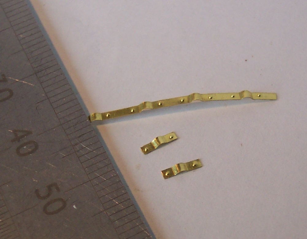
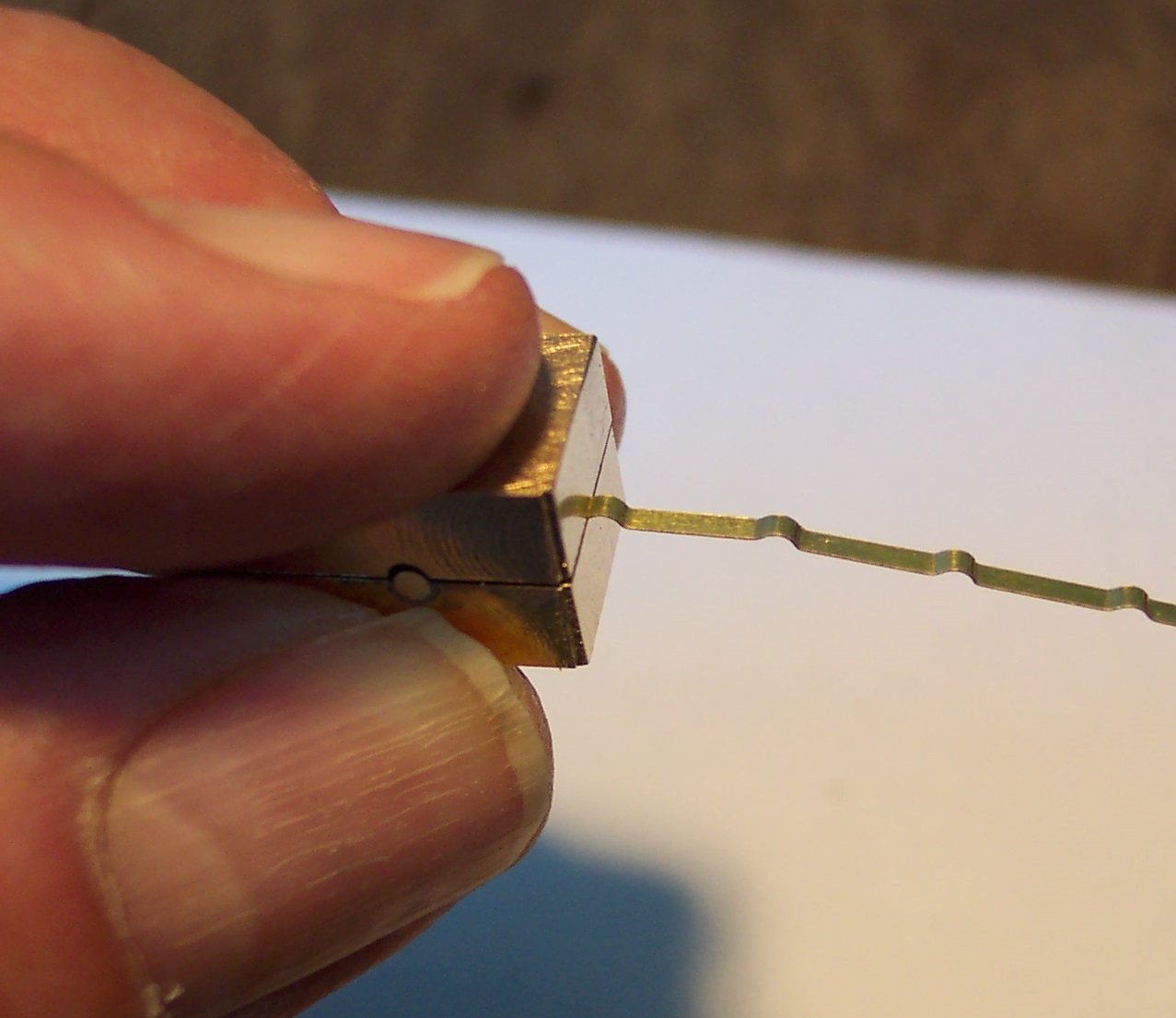
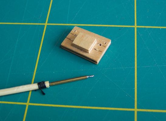
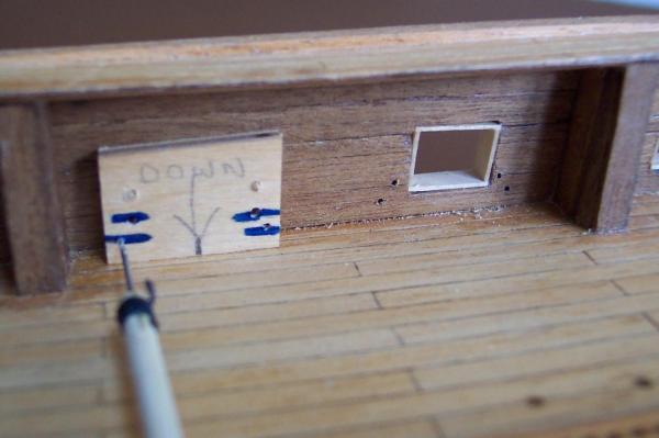
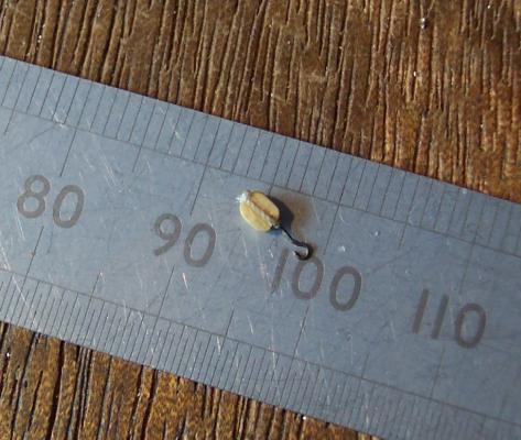
Mike, Spyglass and John, thanks for your input. It has helped me immensely. I decided to go with the side tackle being horizontal so changed the drilling jig accordingly. The breaching tackle will be mounted lower and wider appart which I think fits in with what you guys are saying. Re the blocks. They are rather meaty for these cannon but I decided to go with "off the shelf" blocks. The wood that I possess is too crumbly for making small blocks and (since I am only ever going to make one ship) I don't want to stock up with good quality wood that would get little use - a bit negative I am afraid. The smallest ones that I could lay my hands on were 2mm as in the photo. John, glad you liked the loco models. When I get back to them I am/will be making models of actual locos that I saw and traveled behind in my youth. Nostalgia is not what it used to be. Meanwhile, back in the workshop I stole and modified another of Dafi's ideas. Because the bulwarks are pretty inaccessible I made an extended drilling tool which can be fed through the gun port opposite to the one being drilled. With the usual no expense spared approach it is made from a kebab stick. The end is drilled to hold the bit. The other end I gripped with my normal collet holder to give a hand grip. It is in the following photo along with the modified drilling jig. It worked well - too well. The third hole that I drilled went straight through and out the other side of the bulwark. Pathetic really. So I used some brass tube with an internal diameter that was an easy sliding fit over the bit and cut a length of it such that only 3mm of bit protruded beyond the end. This set the maximum depth of the hole. The next photo is the tube alongside the bit..... ....and with the tube fitted. Drilling the holes was then simple. With the jig plugged in to the gun port the tool was used without the tube in place just to spot the 4 holes. Then the jig was removed, the tube fitted on the bit and the holes drilled to their final depth. You can see on the jig that two of the original holes are blocked up and the new holes marked blue to avoid confusing myself. The adjacent port has the holes already drilled. Then it was time to fit the first rigged cannon. I went for one of the easier positions first. Using hooks in to rings actually made it much easier that I expected. I fitted the side tackle in to the bulwark first (without the cannon in place) then roped them out of the way. The breaching ropes were fixed with the cannon in the run in position to give room to get at the ends of the ropes. Then the cannon was glued in place in the run out position. Finally it was just a case of dropping the side and train tackle hooks in to their respective loops/rings. Of course I made a couple of boo-boos. The first was that I had the cannon with its rear slightly too far forward so it was not directly in line with the train tackle. The second was that I used liquid super-glue to pin the breaching tackle to the deck in its final position. I had used the applicator on some blackened parts and I think it must have picked up some of the "black" (despite my burnishing the blackened parts). This was carried by the glue in to the rope and darkened that part of it. Doh. I will revert to dilute PVA for the ropes in future. This all became apparent after everything was glued up solid. Yet to be done on that cannon is to put some rope coils in place. It is now going to be a lot more of the same. I have gone in to production line mode for the remaining cannon. I made a component list for all the bits I need to make for the rigging. It is amazing how their numbers build up. I will be rigging 16 of the 24 cannon and will require: 96 off large split pins 64 off small split pins 16 off deck rings 64 off hooks 96 off blocks 32 off caps ...and of course another 15 cut splices for the breaching tackle. I may be some time. In the meantime I am off to Anglesey for a week with my wife. Hopefully the weather will be kind to us.
-
Mike, That looks very nice. How does it compare size wise with the Lyme/Unicorn?(With the one being 1:75 the other being 1:64 scale)
-
Freek, Brilliant. I really enjoyed the video.
-
Mike, Nice work. I think the painting in wood will work well. For me the main thing is, if possible, to use the same batch (of each type) of wood for all of the ship to ensure even colouring. Another point is not to spend an extended period (say 40 years as in my case) in completing the construction so that all the wood ages together - or you end up with an interesting spectrum of colours such as the pine on my ship!
-
Freek, Beautiful result. I wish I could be there for the launch. Instead I will have to wait for the videos that I am sure you will be taking of the event. I look forward to it.
-
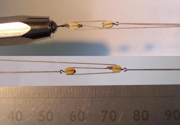
Thanks for the likes guys. I have made up the sets of tackle for one gun. I am including a train tackle. I have looked at the debate as to whether to include this or not. I decided to go with them. I put each set of tackle under an external stress test ie a good stretch. This was to see if anything such as the hooks would let go before I assemble them on the ship proper. The photo shows a couple of sets under test. The upper one is a set of side tackle. The left end has no hook but is lashed straight on to a homemade split pin. The lower one is the train tackle set with hooks each end. No working sheaves like Grant's 1:90 Victory (here) I am afraid. Thus far everything is holding. Next is to decide on the height of the rings in the bulwarks. I have spent a fair bit of time today looking at examples of rigged guns (full size and model) on MSW and elsewhere. No two set ups were the same. I think I could safely say I could drill the four holes in almost any pattern and it will agree with someone somewhere. Then I will find out if I can (or not) successfully hook the tackle up in situ. Watch this space for some embarrassed coughing.
-
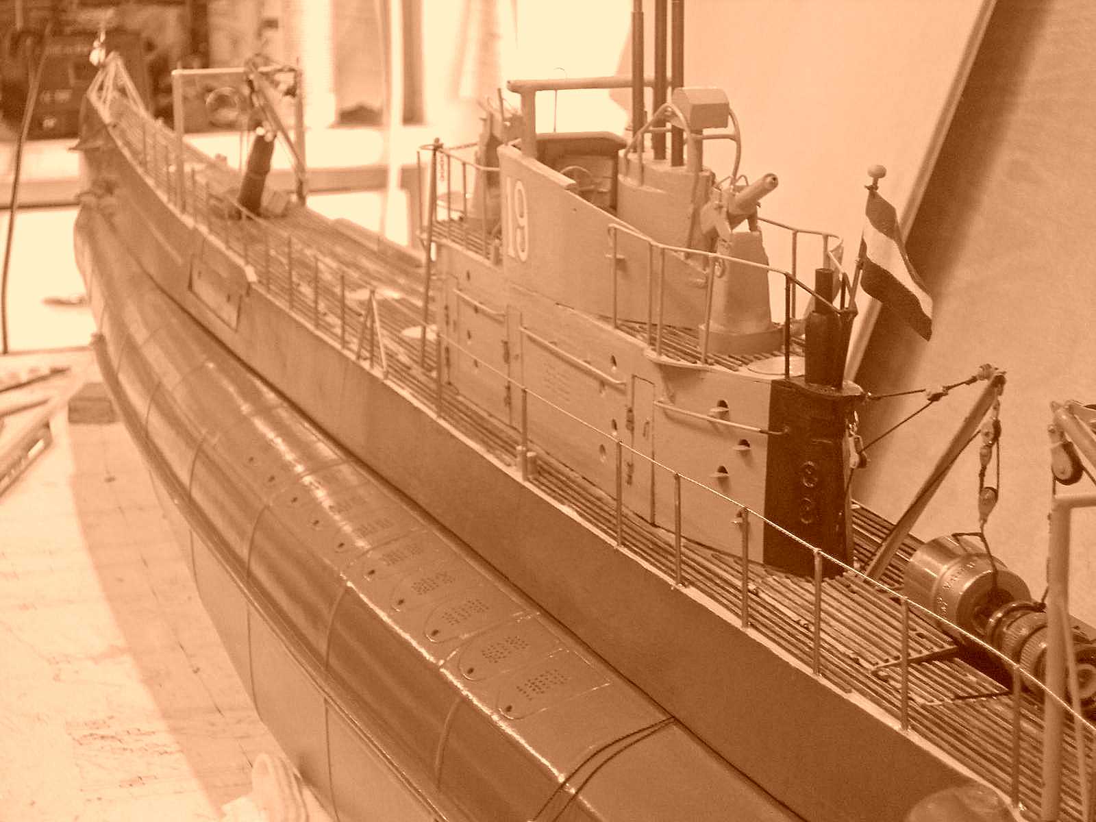
Piet, Your comment on the photos "I think they are self explanatory" is absolutely right. The quality of workmanship speaks volumes for itself. I was looking at the photos of your model alongside those of the original. I couldn't resist the urge to take one of your colour photos and convert it to sepia. It produced a really moody result. With a little darkening of the image and the replacement of the workshop items with something more suitable you are getting very close to the image of the original. (Hope you don't mind my doing this. )
-
Grant, Those davits are superb. Their quality match that of your ship's boats. I had to remind myself of the scale - I was beginning to think it was 1:32 rather than 1:90.
-
Beautiful work on the hull. And that lion - you can count its ribs and knuckles - fantastic.
-
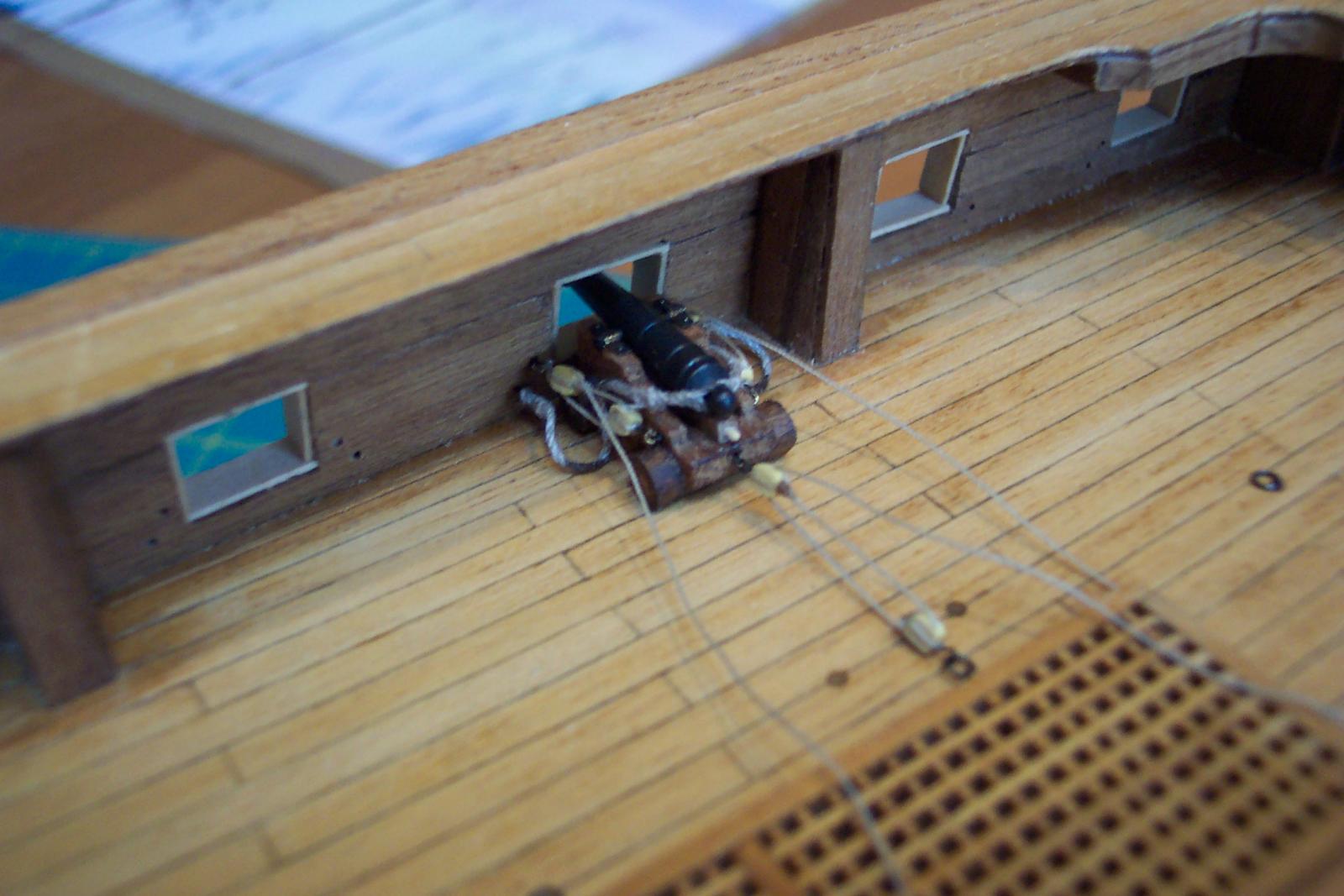
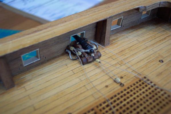
Mike, Spyglass and Grant, Thank you for the input and thanks for all of the likes. The consensus is that the hooks can be shortened - so I made a set with the hooks shortened by 1mm specifically for cannon rigging - then I rigged up one of the side tackles. For this I used one hook/block plus the second block without hook. For practical reasons the blocks at the bulwark I am lashing directly to the ring in the bulwark. I didn't think I would be able to engage a hook with the cannon under the overhanging deck in the waist area. I will use the long hook blocks for the tackle falls where I think they will be OK. The following photo has this side tackle in place. The ring in the jig is not permanently glued in place so I can't pull the side tackle tight without pulling the ring out - so it is rather slack in the photo I am afraid! I have been debating with myself about the position of the rings in the bulwark. I have seen them illustrated in various positions including all four rings in a horizontal line with the breaching rope rings outermost. With the side tackle in place I think I have the rings too high. In practical terms the loaders would have had great difficulty getting at the muzzle of the barrel with the tackle at this height. Any thoughts? When I get their position right I can produce a small drilling jig to help prepare the final holes in the ship.

-
Mike, Those extensions will look a lot better than the original on the completed model. Have you considered drilling a couple of holes through the new extensions in to the original and then use some doweling or brass rod to pin it? The holes will be blind and once the planking is done the end of the doweling will be covered and locked in place for all time. The extensions will not be able to move up, down or side to side locked this way.
-
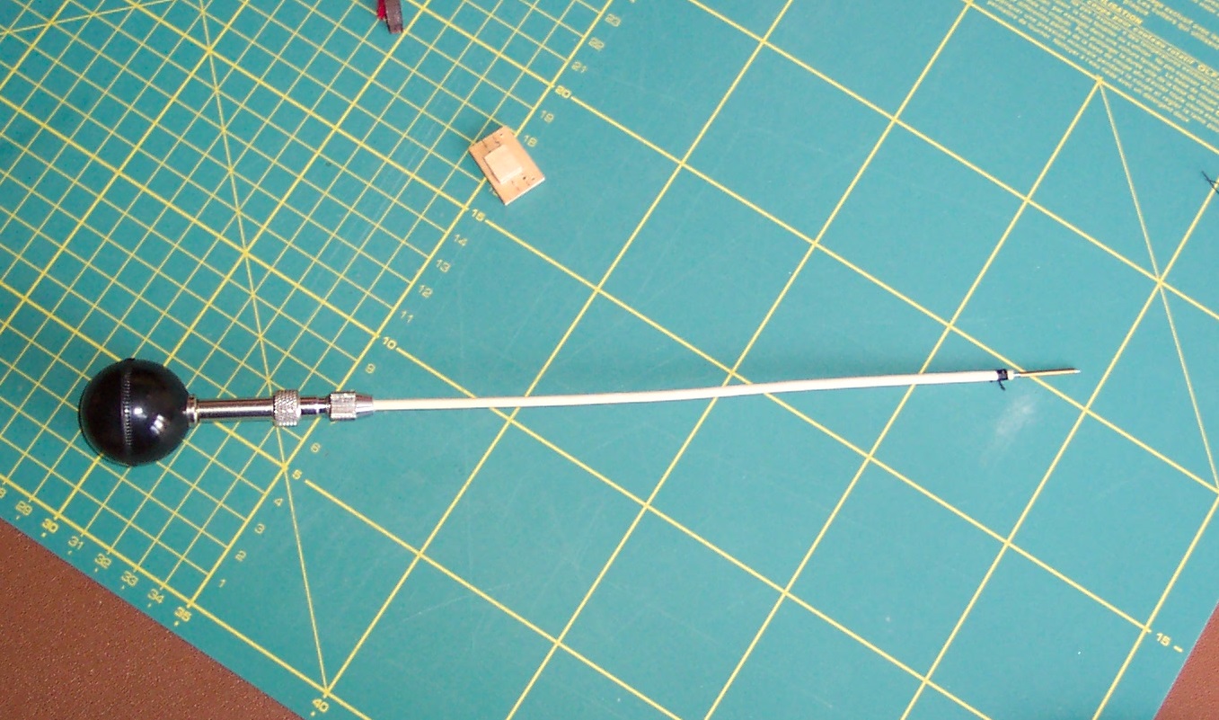
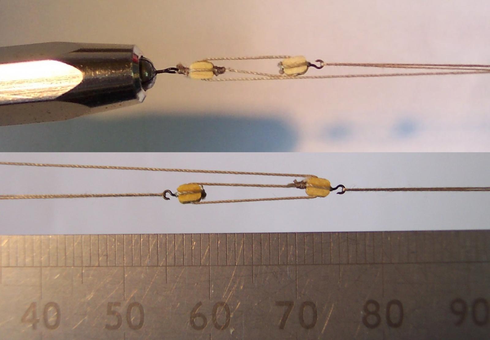
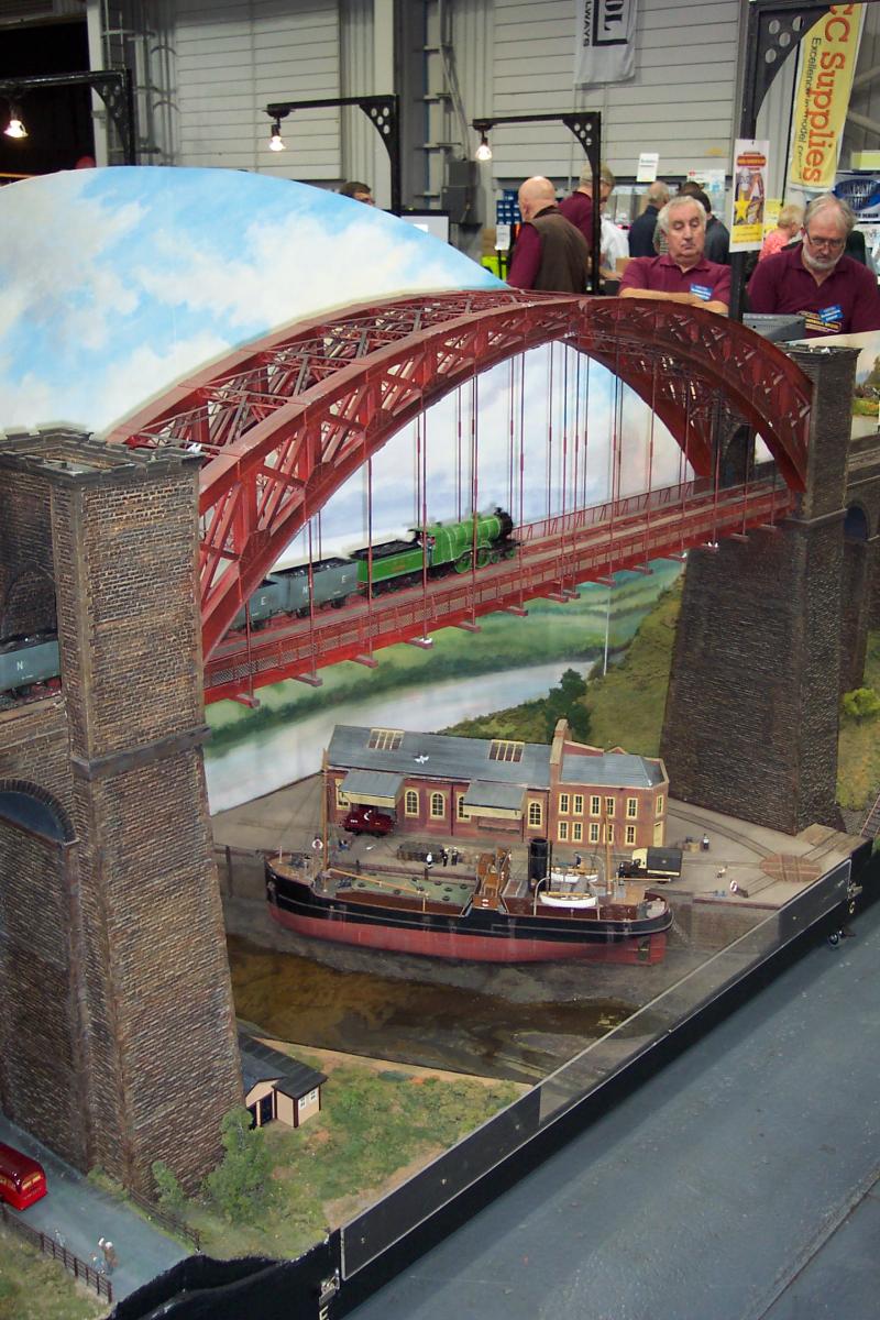
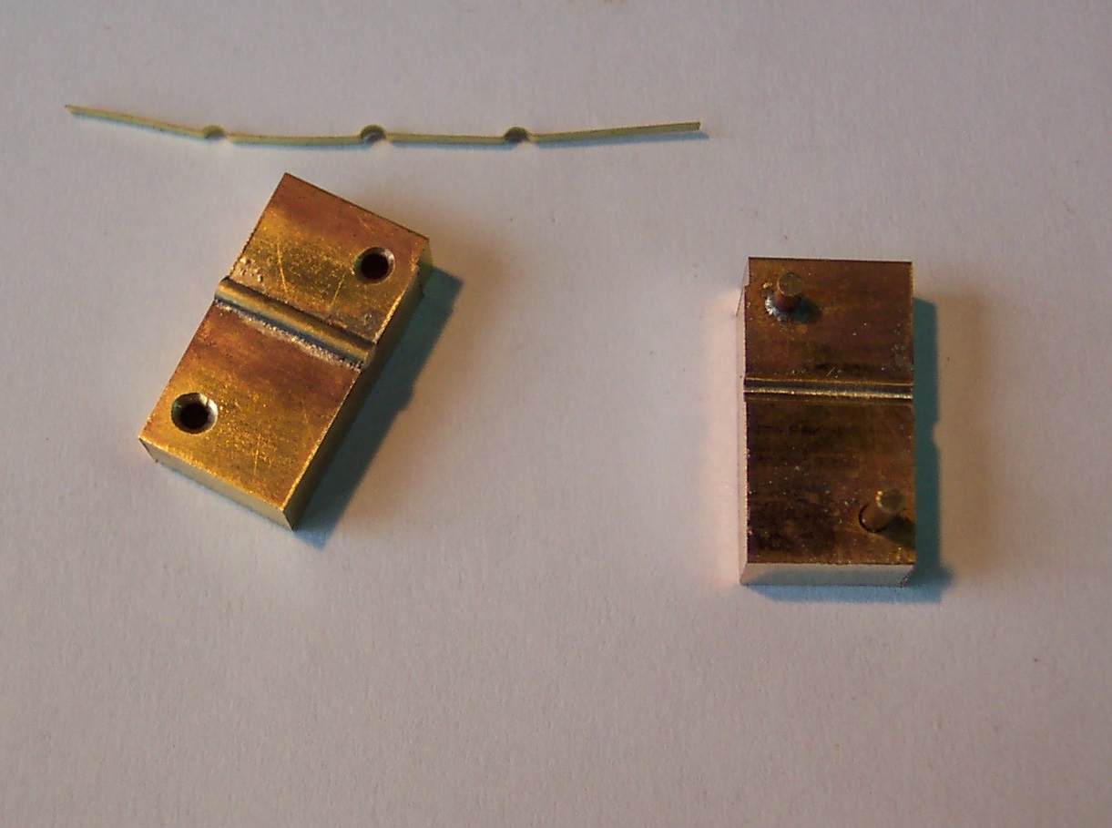
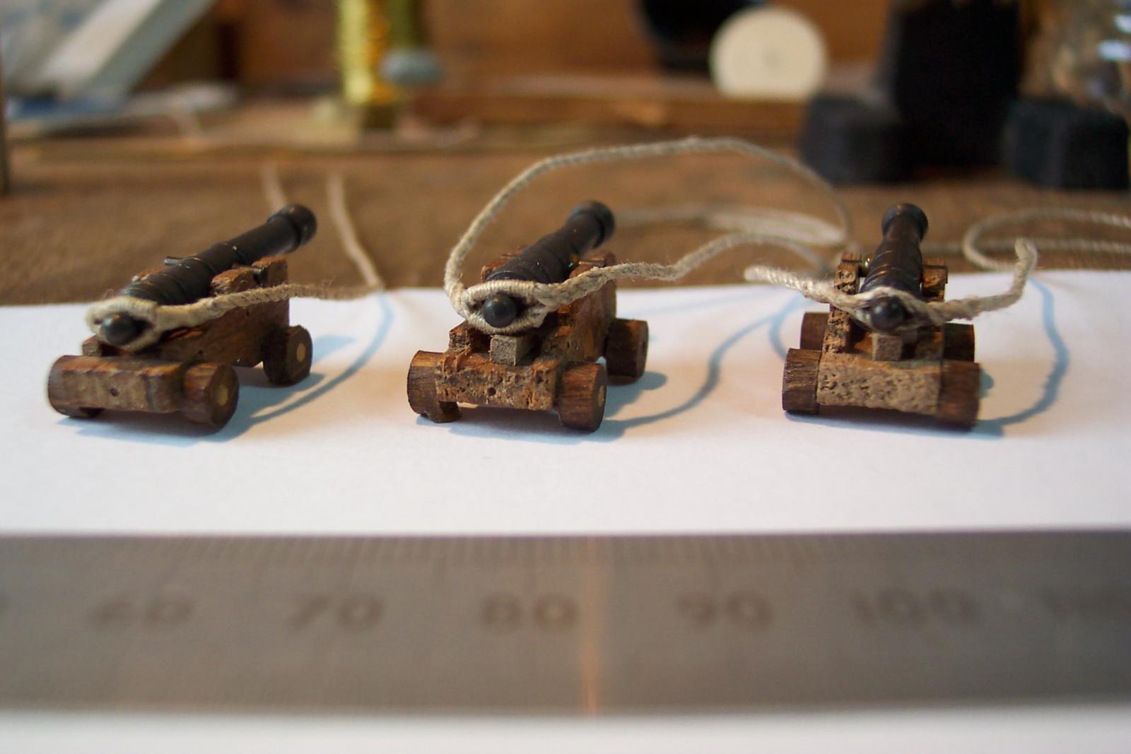
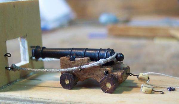
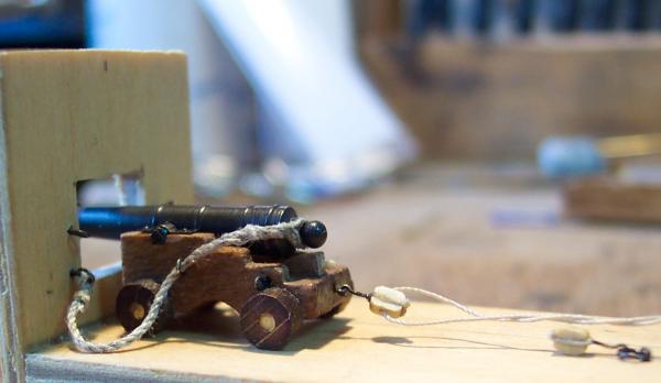
Hello Mike, Glad you liked the jig. It produces reasonable results and it is a nice and easy thing to make - it has to be for me to cope with it. I had a good session at Telford and got stocked up with metal bits and pieces. The following photo taken there is of a good example of ship and railway modeling coming together in 1:43 scale. The bridge stands over 5ft tall. Back to the cannon. I finished off the quoins with handles. These I made from tooth picks passed through my draw plate until they were 0.8mm in diameter. I also started on fitting hooks to 2mm blocks. I cheated with these. I drilled 0.4mm through the block then glued the tail of the hook in the block. I used a length of 0.2mm thread. This was twisted slightly to open up it up then the tip of the hook passed through it. The two ends of the thread were then spliced together around the other end of the block. Time to start assembly of the cannon on the jig. First was to finish off the breaching rope. The ends are attached to rings with a simplified anchor knot with the free ends lashed to stop them coming adrift. This was done with the cannon in the "run in" position. I tried a couple of the hook/blocks around the cannon for size. It looks like I need to make the next breaching ropes slightly shorter and possibly make the hooks about 1mm shorter. Any thoughts on this? I then put the cannon in the "run out" position. I need to ensure that the breaching rope is twisted tighter to stop it opening up when the cannon is in this position. The rings on the carriage for the side tackle I had mounted in the vertical position. But hooking the block on to it was difficult - so after the next photo was taken I changed them to being horizontal. Now the hooks drop in easily from above. This cannon is starting to look a little careworn, with all the experimentation done on it, but hopefully the others will get better treatment when I get in to assembly line mode.


-
John, I put a couple of photos in the "Other Hobbies...." thread. Have a look at http://modelshipworld.com/index.php/topic/1940-other-hobbies-interests-or-pastimes-that-you-enjoy/?p=46650 . The first engine was the one with the two rings of rivets. It is complete but needs a trip in to the paint shop. It and my other locos are waiting on Unicorn.
-
Grant, No problem. Actually the rivets made with the MK II tool look better in real life than in the photo above. I can't get a decent view with my camera.
-
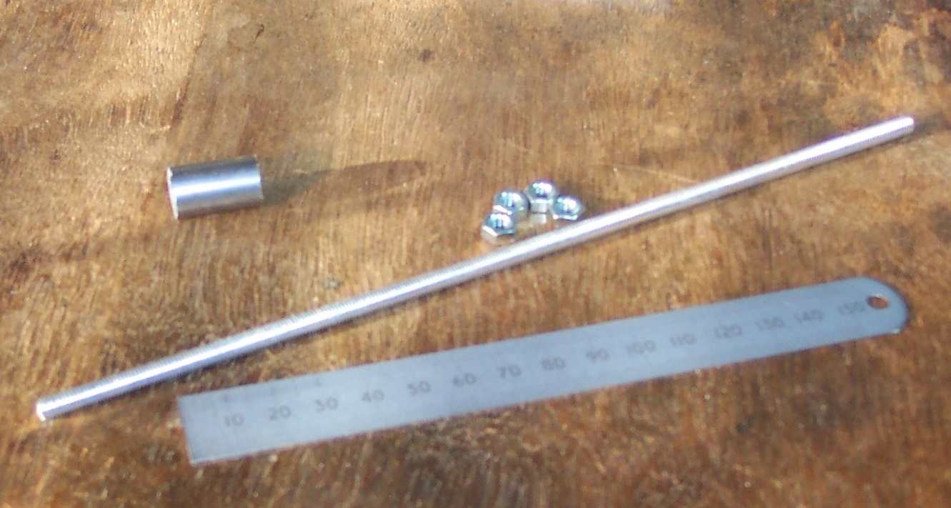
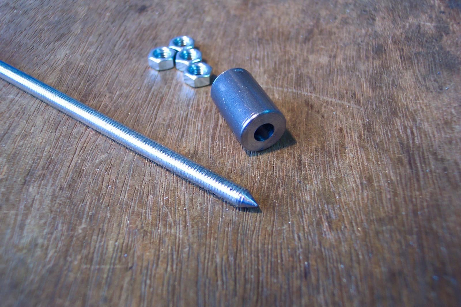
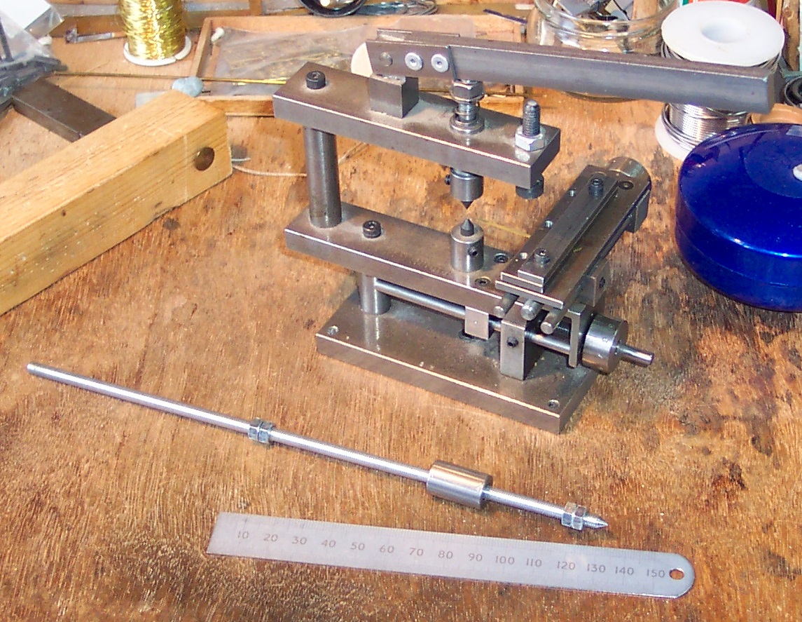
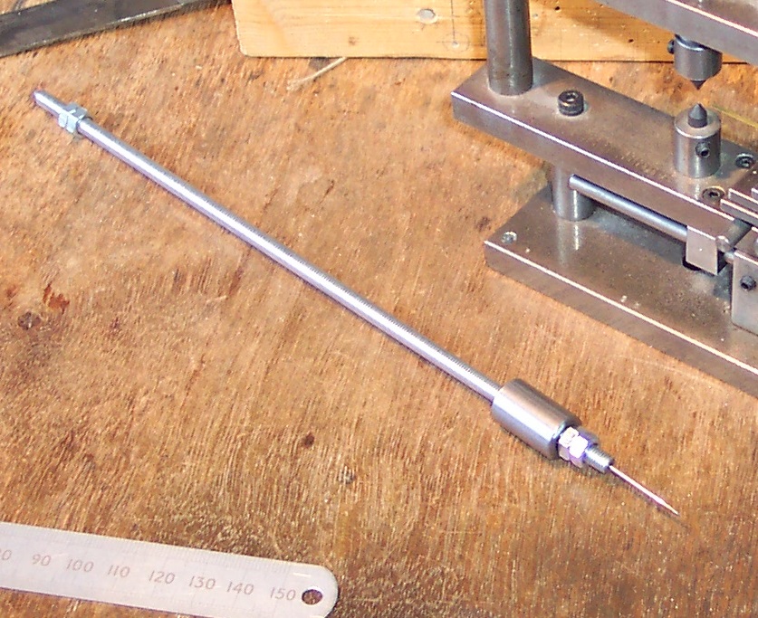
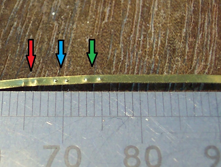
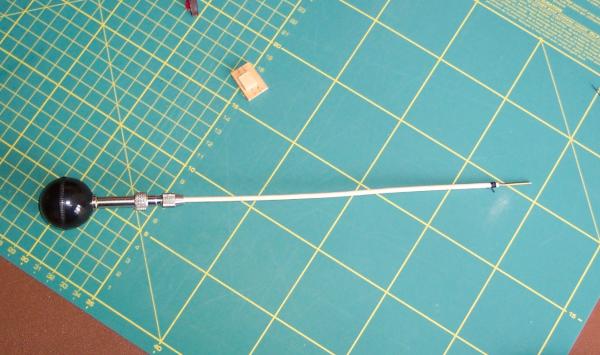
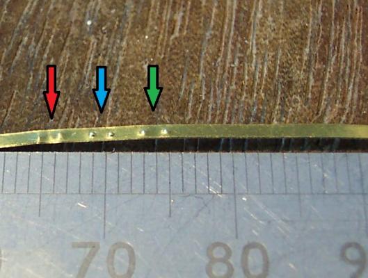
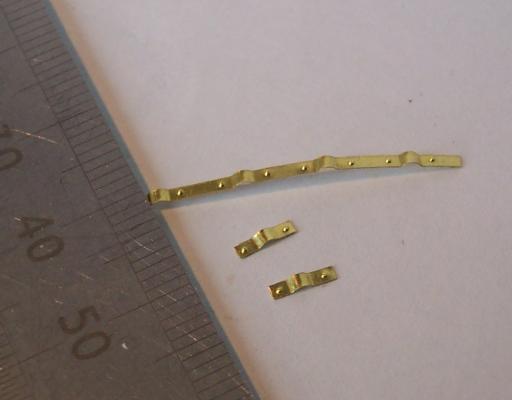
It is possible to press cosmetic rivets using a centre punch and small hammer. The challenge is to consistently hit the punch with the same force or else the rivets come out in different sizes. Many of the railway modelers use a press that is simply a sharp point on the end of a rod. The rod has a weight that will freely slide up and down it. The rod also has adjustable stops. The idea is you position the point where you want the rivet to be, with the rod perfectly vertical. Then raise the weight up to the top stop, let go, it then falls hitting the bottom stop, pushing the point in to the material. The fact that the weight drops the same height each time means the impact will be the same each time (according to Newton and his gravity ). When I was in Telford at the convention I saw one of these for sale at £12. It was based on a piece of studding. So on my return I bought a length of M5 threaded studding (cost £1 a yard), plus I had some M5 nuts and a piece of half inch round steel. I filed the end of the studding to a 60 degree included angle point (as on the die of my press). I cut the lump of steel to 3/4 inch long then drilled a 5mm hole through the centre. (You notice like all railway modelers I gaily switch between metric and imperial measurements - 7mm to the foot anyone! ) I assembled the pieces using M5 nuts in pairs to lock them in position. The next photo is the MK I assembly. The two nuts to the right, at the pointed end, are the fixed stop. The other two nuts to the left make the adjustable top stop. So I put some 1mm wide brass strip on a piece of pine wood. The wood acting as an anvil - there needs to be a little give. The point was positioned on the material with the rod held vertically and the steel block released from the top stop. I produced two rivets this way, then used my press to produce another two for comparison. The new tool did not produce well defined rivet heads. MK II was called for. I had a hardened steel point from an old pair of compasses. I end drilled the threaded rod and glued the point in to it. (A old darning needle could be an alternative). A also had to countersink the ends of the steel block to stop it catching on the thread when released. The next photo shows the MK II version. This was tried and produced much better results. The next photo shows a comparison. To the left, under the red arrow, the two poorly defined rivets produced by the MK I tool. In the middle, under the blue arrow, the two produced by my press. The edges are crisply shaped by the hole in the anvil. On the right, under the green arrow, the two produced with the MK II tool. With slight adjustment and possibly using something other than pinewood as an anvil even better results could probably be achieved. The narrower point of the MK II tool made it easier to line up the position of the rivet. Not too bad for a tool costing less than £2.


-
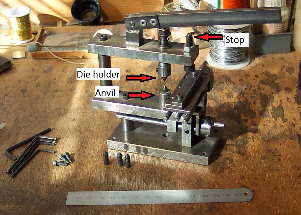
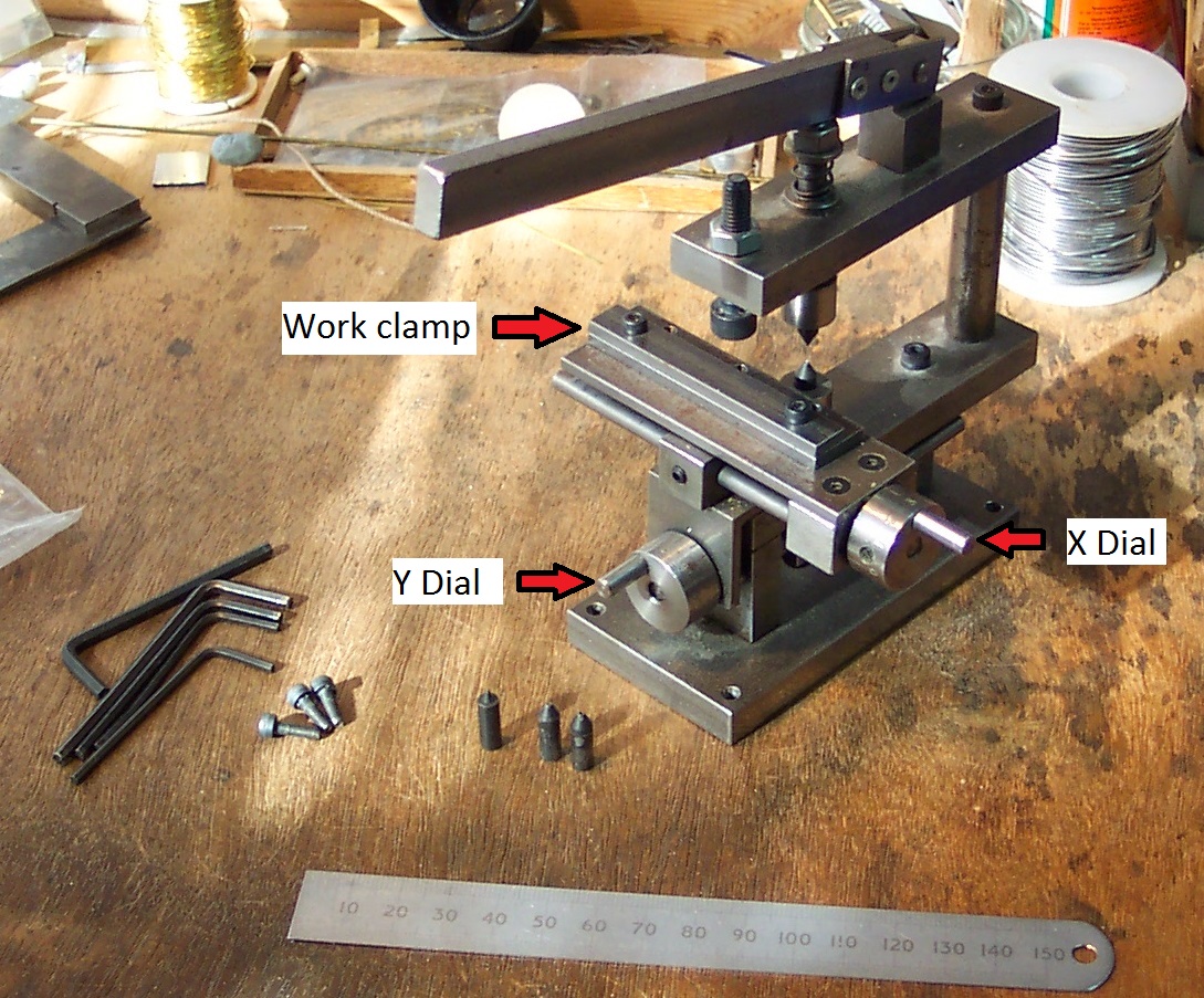
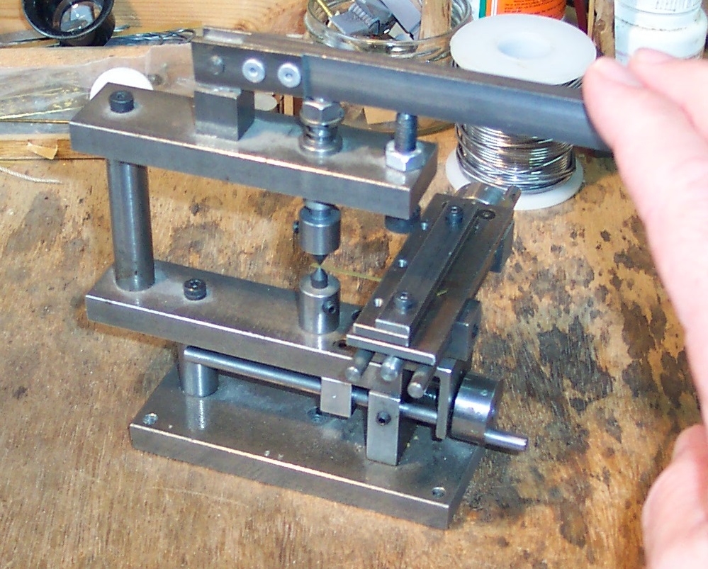
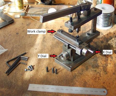
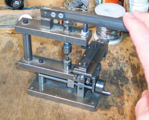
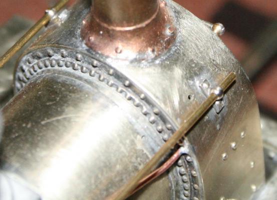
Spyglass, Alistair and Grant, thanks for looking in - and thanks all for the likes. Grant, The rivet forming tool I have is a weird and wonderful looking thing. It is not the easiest of tools to use but it can produce very good results. I have successfully produced complex rivet patterns on brass and styrene sheet with it. Basically the rivets are formed by a pointed die pressing the material in to a hole in an anvil. The press came with three anvils each with different size holes so that cosmetic rivet with heads of three different diameters can be produced. The first photo shows the general layout. The press is operated via the horizontal lever at the top. Consistent pressure on each rivet is controlled via the adjustable stop. For very thin material the die may punch a hole - so the adjuster is backed off to prevent this. In front of the press are the other two alternate anvils plus a die for use on half etched rivet holes in etched brass kits. The next photo shows the operating side. The material is held in the clamp so that it extends over the anvil. The two knobs give X - Y positioning to within 0.025mm. The third photo shows a 1mm wide strip clamped on the press, the lever being operated making the die press down on the anvil. The next photo shows the sort of rivet work that can be achieved with this type of tool - it is the rear of the smokebox of a scratch built loco, the boiler is about 20mm in diameter. I used formulae in a spreadsheet to work out the X/Y position of each rivet in the two circles. Great fun! There are a few downsides to this type of press not least is the fact they cost over £100 stirling. However...............

-
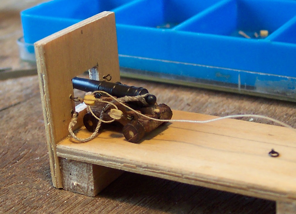
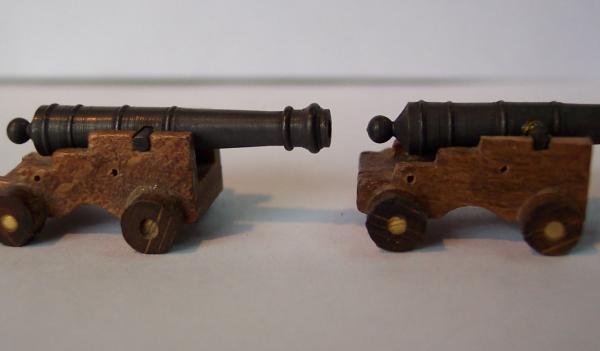
Next was to press some simulated bolt heads/clamps whatever. I have riveting tool which I use in my model railway activities which came in handy here. The individual caps were then sliced off. One problem with the Corel carriages is that the trunnions sit well down in the holes so that a line along the top of the carriage touches the circumference of the trunnion. This is shown by the left hand cannon of the next photo. A normal shaped cap would curve well above the trunnion. I decided to file the top edges down between 0.5 to 1.0mm so the carriage top line would pass through the centre of the trunnion - as in the right hand carriage. A final photo of a cannon with the new thin breeching tackle partially fitted along with (as yet) unblackened caps. The cannon is standing on a jig I made to do the rigging. Yet again a case of my SIFD (Stealing Ideas From Dafi). There will be no ship building for a few days. Tomorrow (Friday) I will be spending the day with the Manchester Chapter of the GOGs (Grumpy Old Gits). We will be sampling the delights of various Mancunian ale houses and having lengthy intellectual(?) discourses. Saturday I will probably spend feeling sorry for myself. Sunday I will be off to Telford to a different set of GOGs. This time it is the Gauge 0 Guild, of which I am a member - so I will be playing trains. It is also where I restock my materials and get any tools. I have decided I need some more good quality long tweezers to help with the rigging.
-
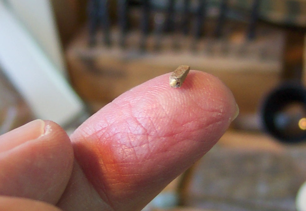
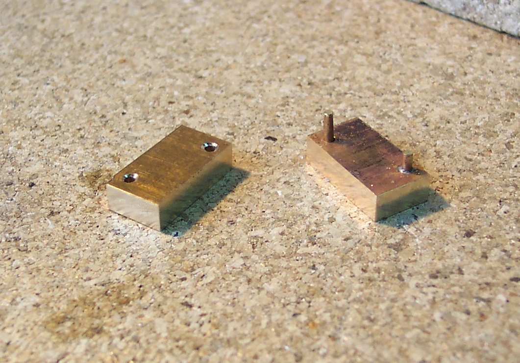
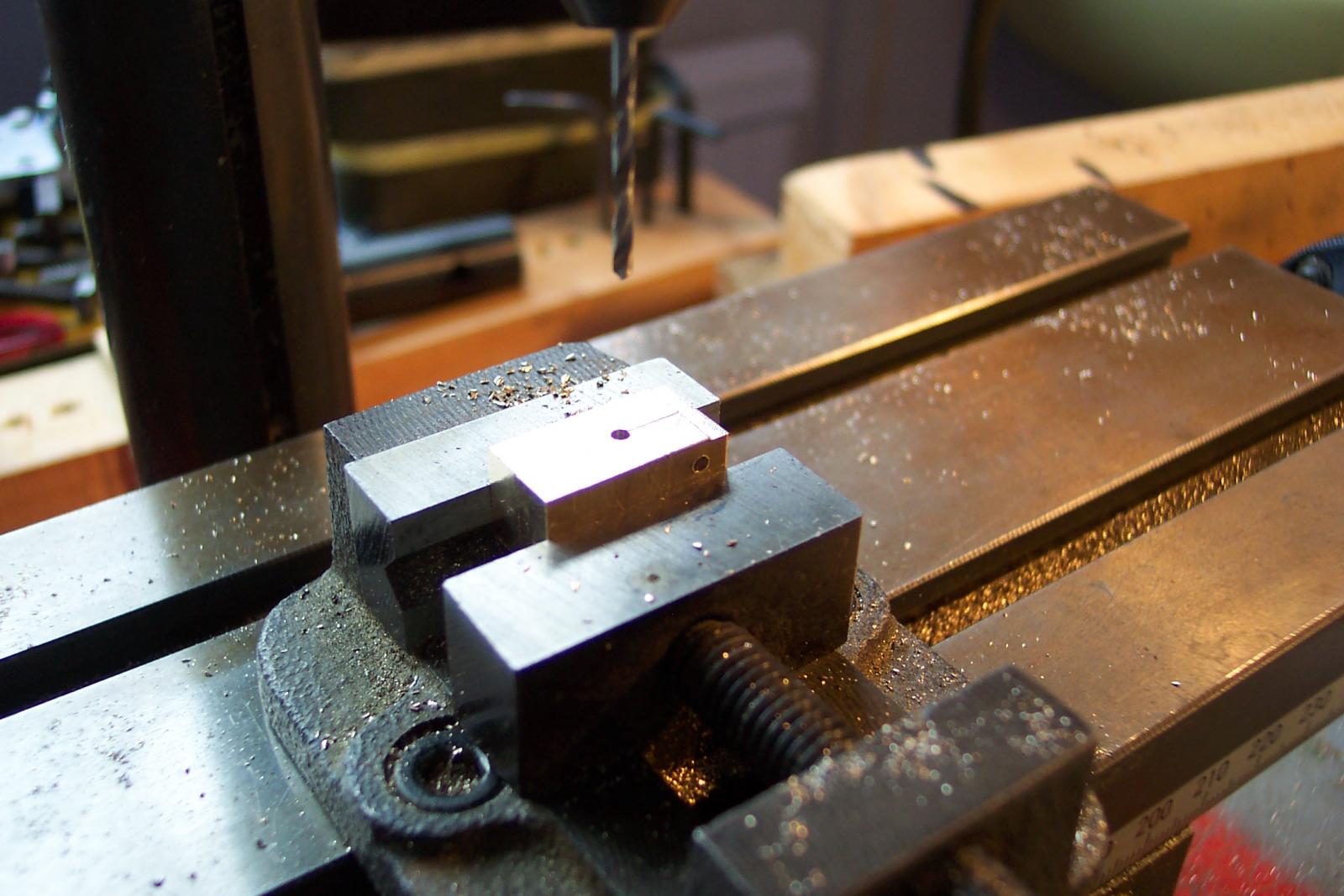
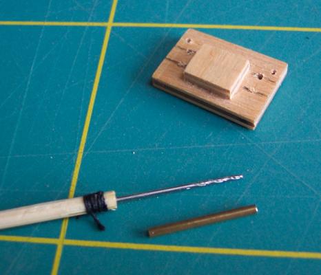
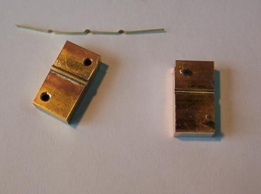
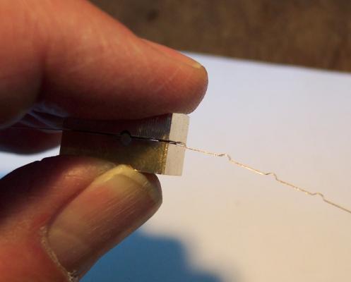
Alistair, Thanks again. I think I may reduce the splices back to two tuck unders to make them a little more compact. I notice from your entry in BE's log about your enjoyment of your "rougher pastures down here". My wife is organizing a 3 week trip to NZ next year for us, so I too will have the opportunity the enjoy those pastures. It will be in the nature of a last great project for us - any more will be a bonus. She has wanted to go to NZ for a long time (so have I) - I think she wants to look for Hobbits (DON'T THROW THAT BRICK AT ME. ) Having decided to make the breeching tackle from 0.45 thread I am now starting to produce the other 15 that will be used. I had already made 8 sets with the thicker thread which will be set aside. In parallel I am preparing the gun carriages ready for rigging. I have the wedges for the quoins ready. I need to produce some caps to hold the barrels down. To shape these I made a rather crude die. Very easy. I started with two pieces of scrap brass and some 1.5mm brass rod. The two bits of scrap I clamped together to drill two 1.5 holes through them and soldered short lengths of the rod into the holes of one part. I then pushed them together and used my miller to make them rectangular and the same size. I clamped the two pieces together with a long face uppermost and the join between the two in the vertical plane. Then using a 1.7mm bit I positioned the tip of the bit on the join then drilled down through them. When the two parts were separated they were each left with a semi circular cross sectioned grove. I then soldered a length of 1.5mm rod in the grove of one of the parts. Cleaned them up then and them together to make sure they fitted. A little more cleaning around the pegs was required then all fitted well. On the left of the next photo is the part with the rod attached across the middle, the right hand one has the pegs and groove. Above them the results of a test press. The results are not perfect, I should really have taken a skim of about 0.2mm off the face of the left hand one before fitting the rod to give some clearance for the material to be pressed - but at normal viewing range the imperfections are very hard to see. I will be using brass strip 1.5mm x 0.2mm. This is so thin that I won't need to use a vice to squeeze the die just my agricultural bodgers. The next photo shows the tool in use. Using a 1.7mm drill bit to make the lateral hole and using 1.5mm rod in the groove leaves a clearance gap in the "shaping" area. Note the lateral hole/rod is nearer to one end. The distance from the rod to the end of the die will determine the distance between each pressed lump. A slightly different view of the tool in use.


-
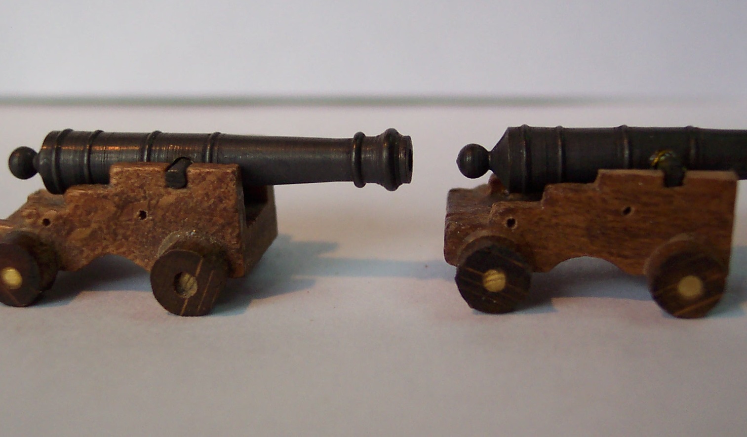
Thanks Grant, You have to admit those old Corel gun carriages have an air of realism in the way they represent large amounts of schrapnel damage!
-
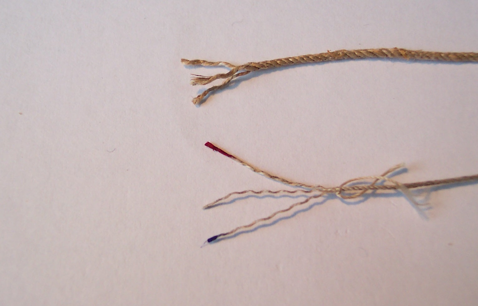
Thanks guys for the likes and input all of which is greatly appreciated. John, Glad the drilling for the bowsprit went well. Mine will be a butt fit I am afraid. In the same area I am trying to work out how the boomkins are rooted - did they fit in a socket or what? Alistair, Thanks for your input. I also felt the 0.7mm rope was rather well fed. Some of it I tried to darken by soaking in tea (after I had drunk the rest). Result was that the rope swelled to 0.8mm diameter. I had a look at your Fly to see your cannon rigging which is very nicely done. (For those interested look here for an example from the log). So - you used 0.6mm at 1/64 scale which equates to a diameter of 38mm full size. Scaling back down to 1/75 gives me 0.51mm diameter. I have some 0.45mm thread (nominally 0.5mm) so I used that to have another go. The next photo shows the two thicknesses side by side. The new thread is laid the same as the thicker thread. I have opened it out for 20mm and stained two of the tips so that I have one red, one yellow and one blue (anyone for three phase mains supplies! ) so that I can keep track of which one is which when splicing. The stained ends will be cut off on completion. The splicing approach was the same as before except the thinner thread allowed me to use three tuck unders giving a splice that was firm even before I finished it with diluted PVA. In the next photo I compare the results. The thicker one on the left, the new thinner one on the right. How's that (as they say in cricket)?
-
Gosh Piet, Your log has reached page 100! A volume packed with all sorts of interesting goodies. Give the medics the run around and look after yourself.
-
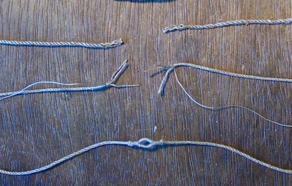
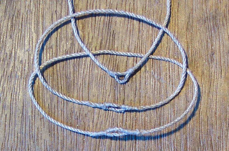
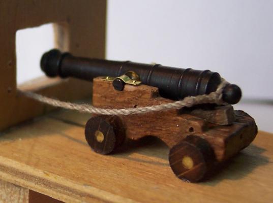
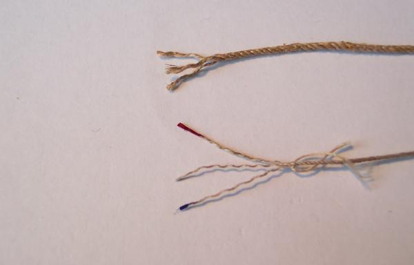
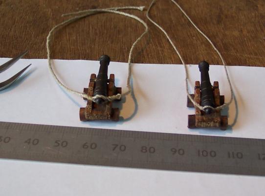
Mike, Joe and Peter, thanks for looking in and for your kind words. I have bitten the bullet and started rigging the canon. I began with the breeching tackle. There are no eyes(?) above the cascabels to pass the rope through. I have seen breeching tackle wound around the cascabel but I decided to use cut splices. An interesting challenge! I used some of the 0.7mm rigging cord supplied with the kit. This consists of three strands shroud laid. Each strand is made of three finer strands laid the opposite way. My first three attempts at the cut splice are in the first image. The approach was to reduce the ends down to a single strand for 3mm then to use whipping to secure these single strands in place. The first one came out asymmetric. It looked neat but the real breeching tackle would unlikely be like this since all the strain would be on one half of the splice splice. (Top splice in photo) The second one down in photo is again a false splice but I managed to make it symmetric. Sadly the points at which the three strands are reduced to one stick out like sore thumbs. It looks ragged. The third attempt in the photo I reduced the ends to two then one strand over 5mm and used longer whipping to cover this. It looked better but I was still not happy. The next photo covers my next effort. For this I whipped each end for 4mm leaving 10mm free which was opened up. The whipping is a standard type I learnt in the cub scouts nearly sixty years ago! The one leg of the whipping was left very long. The two whipped parts were clamped side by side and the free ends spliced in with one tuck under and trimed off. The two long legs from the whipping were then served around the splices giving the final view in the photo. It looked much better. Time to try them on the cannon. This last splice is fitted on the cannon on the left of the next photo. I had not been using proper splices because I thought they would look fat but for the next one I decided to give it a try. I still used the whipping in the centre of the splice but this time made both halves of the splice with two tuck unders. Giving the rope a twist from both ends tightened the splice up and it was held firm with diluted PVA glue. This is in the middle of the photo. Still not happy. They look like they have big mouths with wide grins. So the final one I dispensed with the whipping altogether. I spliced one end in to the other rope 20mm from its end. The splice was tightened by twisting as before then glued - being clamped whilst the glue dried. Previously I had used the whipping to fix the size of the splice. For this effort I used a cannon barrel and made the second part of the splice tightly around the cascabel - making sure that it remained symetrical. The second half of the splice was glued as before then the ends trimed off. The result is on the right of the photo. I think this looks much better - in fact to get the barrel free would require the spliced to be cut off! Any thoughts on this? For the photo I have managed to use one of the 4 carriages that will be surplus to requirements - it is rather rough as can seen. The cut splice is basically 2 eye splices in tandem. I used the Animated Knots web set for inspiration. See here.