HOLIDAY DONATION DRIVE - SUPPORT MSW - DO YOUR PART TO KEEP THIS GREAT FORUM GOING!
×
.jpg.f4fa790b1fa2f0e00e3d149ed7bdd37c.jpg)

shipaholic
-
Posts
540 -
Joined
-
Last visited
Content Type
Profiles
Forums
Gallery
Events
Everything posted by shipaholic
-
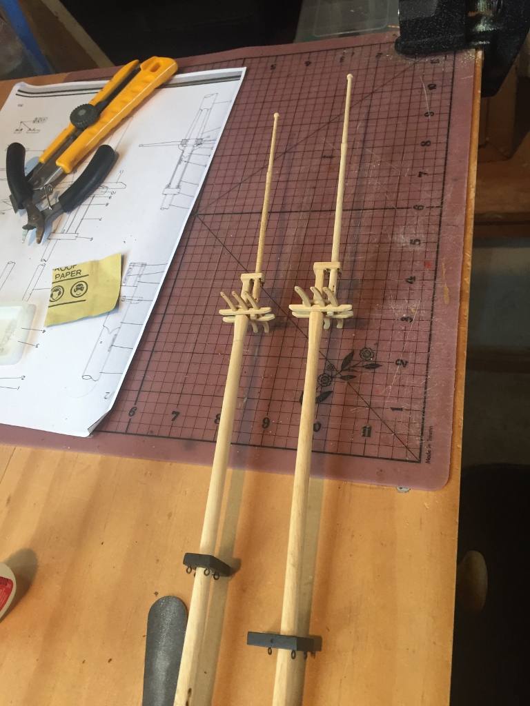
 Thanks for all the compliments guys. Michael (Ca.shipwright) - the metal work is very very tricky and those stunsail boom irons, being so small, were super tricky to do. The hardest part is holding the parts together during soldering, then not getting too much solder. I am not very good at it and it took a few tries to get them right but i persisted. I used silver solder. I have a silver solder kit that I bought, which consists of the solder, a mini gas torch and the flux. I used some 1/8" brass tube for the rings and brass rod hammered flat on four sides to make it square, for the arms. If you look at this photo you will see that the rings are a little off centre but once on the model its hardly noticable because they are so small. There was usually too much solder on the joints so I just filed off the excess. Cheers Steve
.thumb.jpg.f0376bc2808e2486b6f827ca85131b5b.jpg)
-
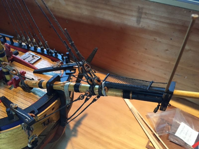
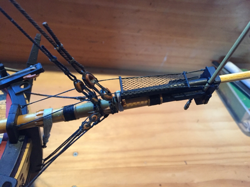
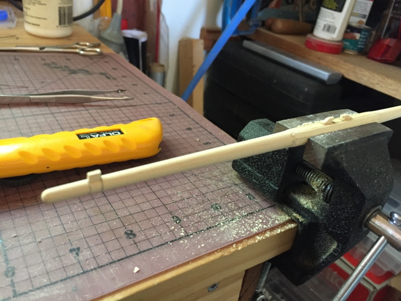
I have been making the stunsail booms, plus I added a few more items in preparation for the rigging. The bowsprit traveller, the iron horse, and some cleats. I fitted the belaying pins to the bow, I used brass ones that are blackened because the are a better more realistic size and I reckon the look just like dark wood once blackened.
.thumb.jpg.448e4e5afbd413f9ba213308d5e268eb.jpg)
.thumb.jpg.b86929daa931797fbf60afdb3606058d.jpg)
.thumb.jpg.f76a6e13bf605b602eca13e2832c34c4.jpg)
.thumb.jpg.9b11481927d16f6b4b938828bb0d60ea.jpg)
.thumb.jpg.6c1de8266d248ea168d21de513b3f87c.jpg)
- 557 replies
-
- 14
-

-
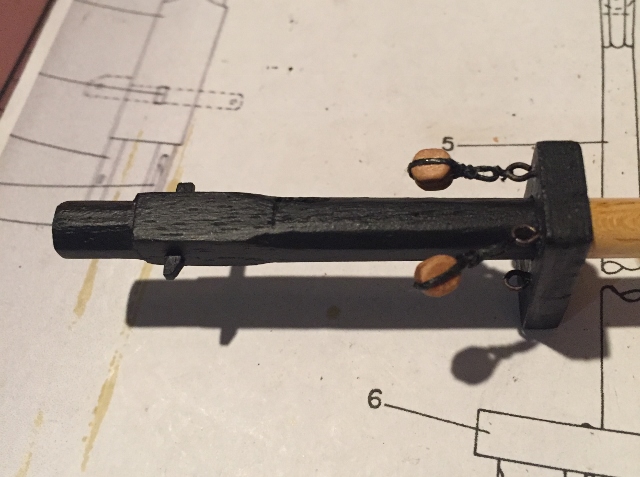
Hi Steve i think the wooden cannons are better, the plastic ones don't look like cannon from that era. The wood ones look more like the real thing. Google search "Cooks cannon" should come up with pics of the cannons recovered 200 years after they were thrown overboard. They are most likely the same type as would have been on the Bounty cheers Steve
- 291 replies
-
- 2
-
-
- bounty
- billing boats
- (and 1 more)
-
I spent the day finishing off the foremast lower yard arm and then painting all the yards.
.thumb.jpg.f572e35685f3abcb3c058ec1ee94a696.jpg)
.thumb.jpg.179372920581dd13990d1ff7ef4d3a85.jpg)
.thumb.jpg.e1a667439cb61f02ad7d44f95fbf82ee.jpg)
.jpg.5b9569481ab55f06993d68c633ecf087.jpg)
.thumb.jpg.1c5a730c44cdbc35fb6ff1393286a42a.jpg)
-
The wood work on the yards may be finished but there's a lot of fiddly stuff left to do on them. Today I started making the studdingsail boom irons. Why aren't the photos showing?
.thumb.jpg.390d8c9c554b6e3ac3ddbb95709cc7a6.jpg)
.thumb.jpg.8d30bb26f79acaf7404a6953c4d293a7.jpg)
-
I have finshed all the yards, a lot of sanding!!. Just need to add the hoops for the stunsails. Now comes the big job of adding all the blocks and footropes
.jpg.e93b6dde020f295bbdded75db176d0b7.jpg)
.jpg.e9174232a90f02fd2531066be5bcfa2c.jpg)
.jpg.ce1b9307231f106bd1b24c5bf43a8f6b.jpg)
-
Thanks BE, yes I agree when the sag happens realistically you know the tension is right. On my previous models I left the horizontal running rigging such as braces a bit loose then soak with water using a wet paint brush which makes the rigging sag realistically and then it stays that way once it dries out
-
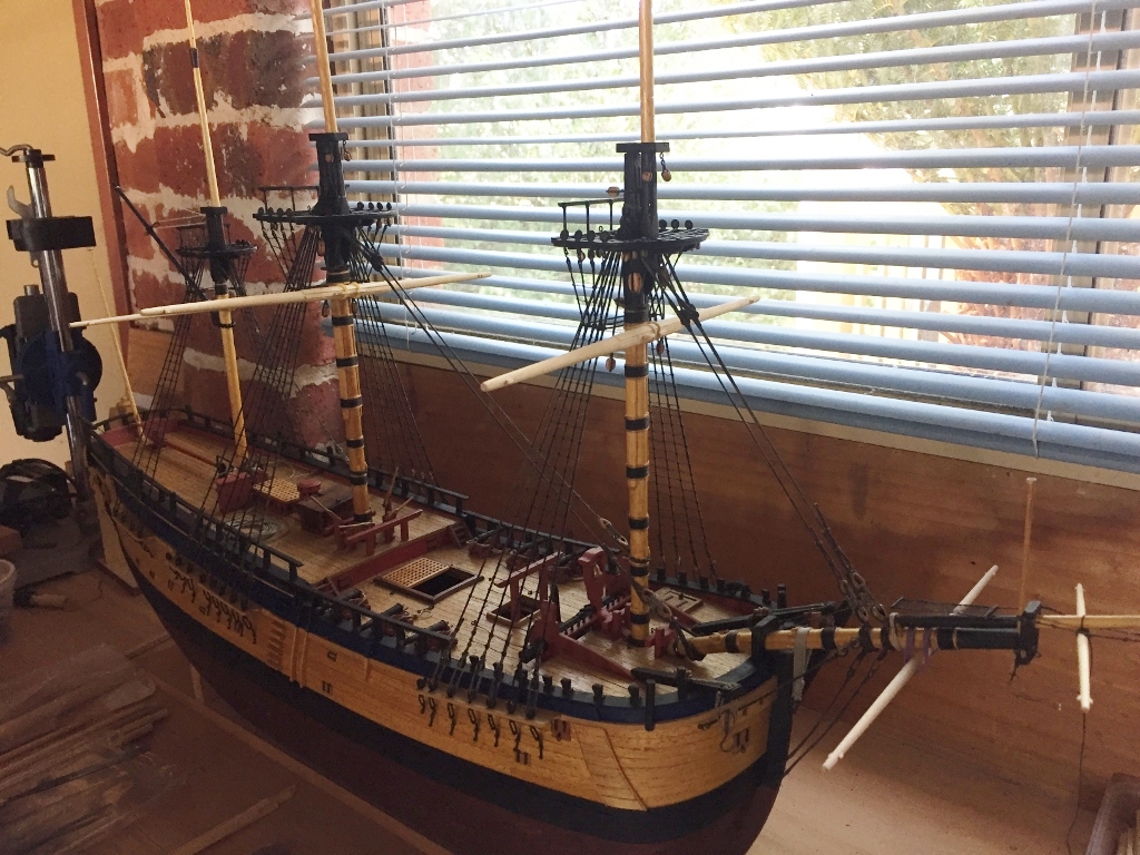
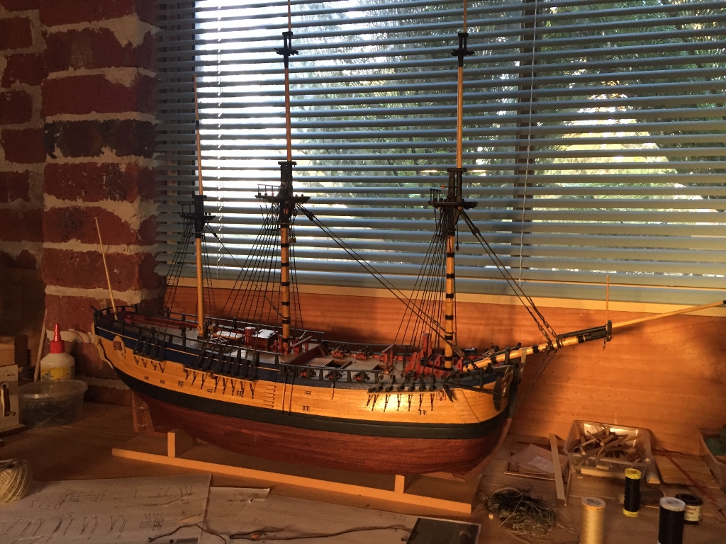
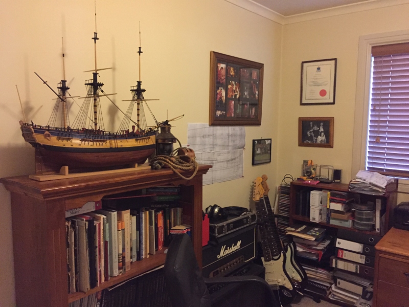
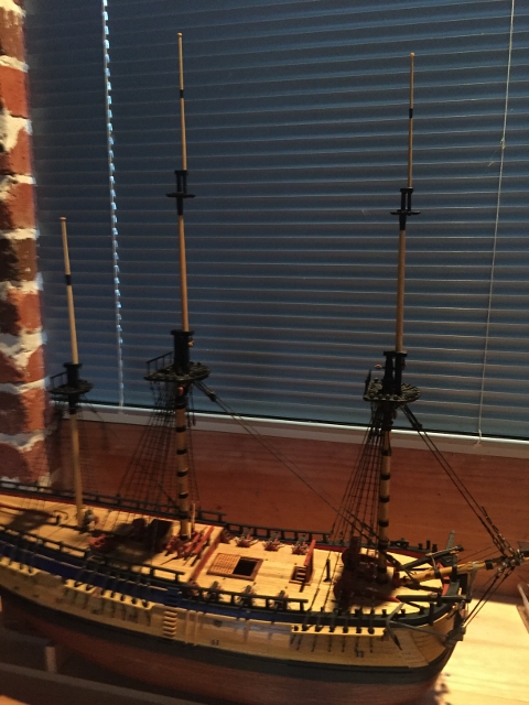
Its 37 degrees Celsius here today and my ship in the garage is suffering the sags, the mainstay especially and the shrouds are loose. I brought it inside and placed it on the bookcase in my study (my indoor mancave) where my Victory normally sits. Looks okay there, my Vic might be looking for a new home when I finish the Endeavour.
-
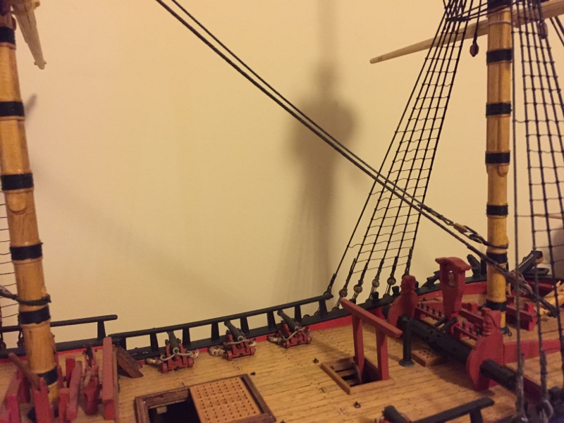
I put some yards in place to see how they look. Iphone lens makes them look a bit thicker at the near end

-
Hi Rexy Nobody knows for sure about the colour scheme for the Endeavour. At the time it was customary to paint a lot of the deck fittings, bulwarks and cannons red ochre, the ships sides were usually painted with varnish of pine or tar (not black tar but sort of like varnish colour), wales were blackened. So very much like the Replica. However the replica has white below the water line because a lot of ships from that time were painted with white lead below the water line, this may be not correct for Endeavour because historical records suggest Endeavour's hull below the water line was coated in what was called "brown stuff". I have done a lot of research and studied many paintings and ship models from that era. I think the replica vessel is probably right except for the white. However I suspect that the blue along the sides could have been blue and red, or even blue white and red, as was customary on British naval vessels at the time. I was almost tempted to paint the sides of my model blue and red, just to be different to the plethora of Endeavour clone models out there Cheers Steve
-
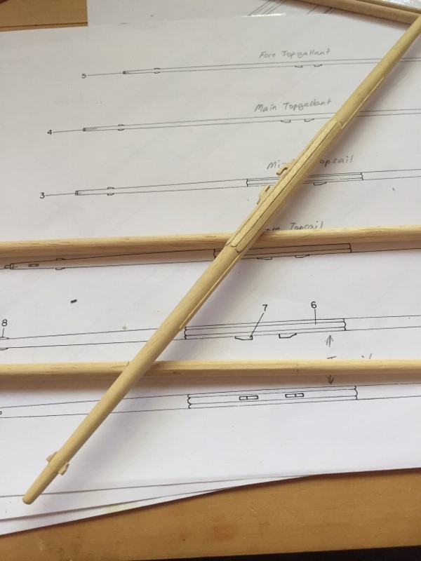
Most of the weekend spent making the yards, all done by hand, just lots of sanding. Something not clear on the AOTS drawings is the fact that the yards that are eight square in the centre section had battens nailed onto the flat sections. The battens were 1" thick so at 1:51 scale thats 0.5mm - the deck planking material is 0.5mm so I used some of the left over planks for the battens. Its terrible open wood so hard to keep edges straight. SIx done six to go. Pics are of the main yard.

-
After a long absence from the shipyard I have started making the yards. Started with the gaff

-
Welcome back Mike, I have been only doing drips and drabs too lately. I am up to exactly the same thing on my build, just finished the gaff and working on the yards Cheers Steve
-
Nice work Dave Regarding the stays, the AOTS is wrong I think, those mizzen stay arrangements are from a later period. The mizzen stay and mizzen top mast stay were set up using dead eyes according to Lees (the replica also has this arrangement) Mizzen preventer stays were not used at the time of Cooks voyage. The main stay, topmost stay and topmost preventer stay are correct in the AOTS Cheers Steve
-
Hi Dave Looking Good You should leave the hoops off the masts like I did. According to Lees' Masting and Rigging of English Ships of War the hoops were seldom seen on models before 1800. Steve
-
Michael, May I answer your question. If your masts are the correct dimensions the topmost hounds should be no larger than the rounded part of the topmost near its base. That way it can raised up through the cap and when in place the cap hole is still a snug fit around the mast Cheers Steve
-
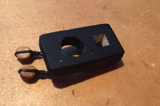
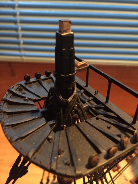
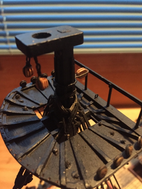
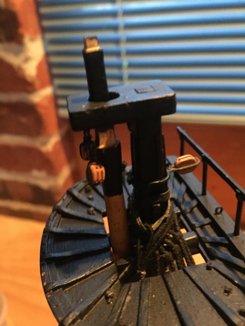
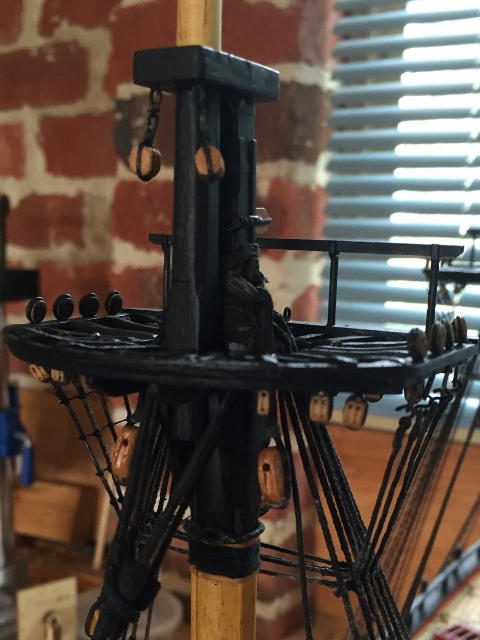
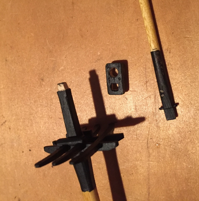
Thanks Michael In relation to your question about caps on Dave Rowe's build, here is an explanation; The cap has a square hole to fit on the top of the lower mast which is squared off Here is the lower mast cap in place. It has a round hole for the topmast. The round hole must be a slightly larger diameter than the thickest part of the rounded section of the topmast As Dave mentioned the topmast is raised through the hole in the cap, once in place the fid is put in place to stop the topmast from sliding back down. In the third pic shows the base of the topmast and the fid. The base of the topmast is squared off and wider than the rounded part so its not able to be slid down through the hole in the cap, that why the topmast must be slid up through the cap. The square part of the topmast base is just smaller than the square hole in the top so it can fit through The topmast cap is the same deal, a square hole for the top of the mast and a round hole for the topgallant mast to slide up through. For model building purposes you can just slide the cap down onto the topmast or topgallant mast from the top It all fits together nicely without glue if all the dimensions are right Cheers Steve
-
Hi Dave and Michael I will post some pics on my build log showing how the masts and caps work Cheers Steve
-
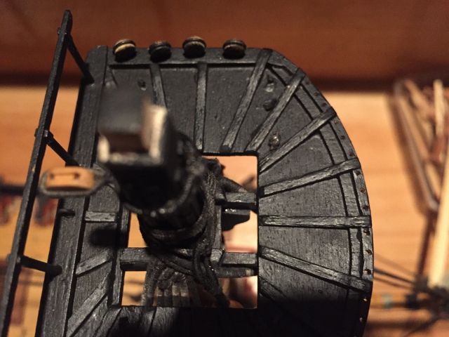
Hi Dave Good pic of the replica top. Shows how the battens have a curvature, a point missed by many plans etc
-
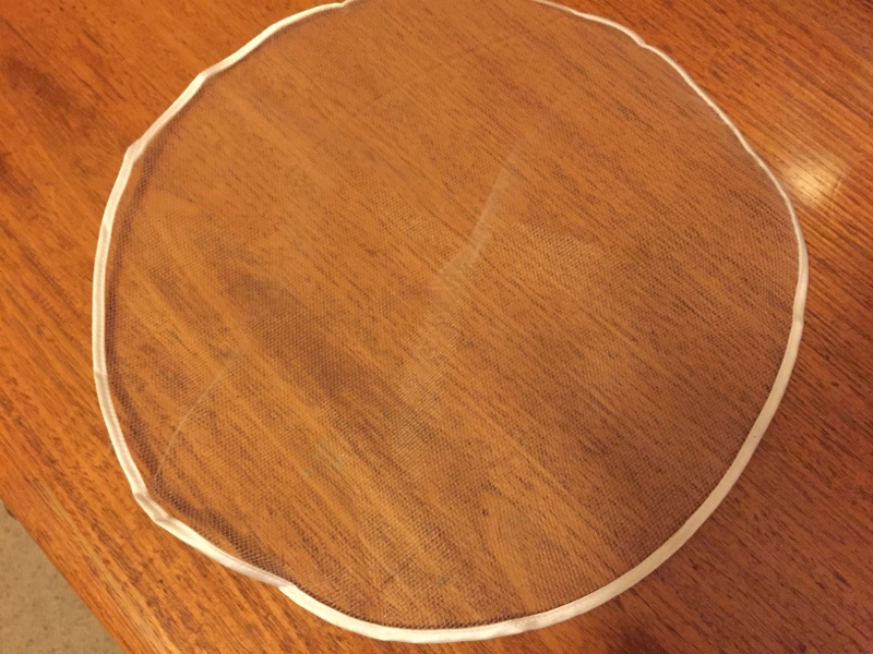
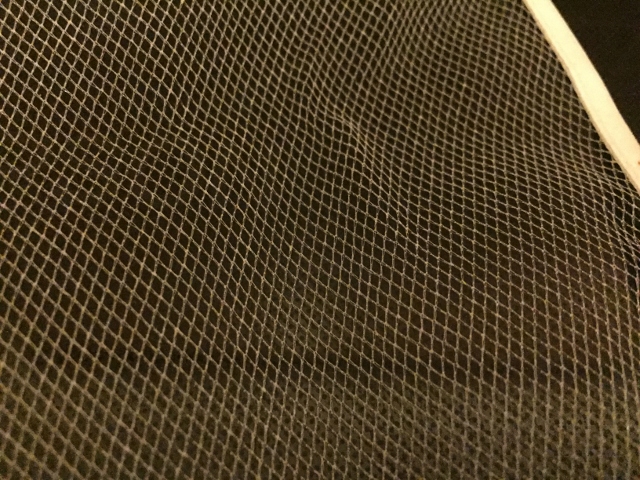
Hi Dave I used this mesh it came in a pack of 10 of these circles that are 30cm diam, it was long time ago that I bought it, can't remember where I got them, it was either Spotlight of Lincraft. If you can't find something similar I could post you some. I still have 9 unused ones Cheers Steve
-
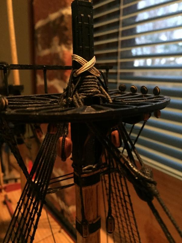
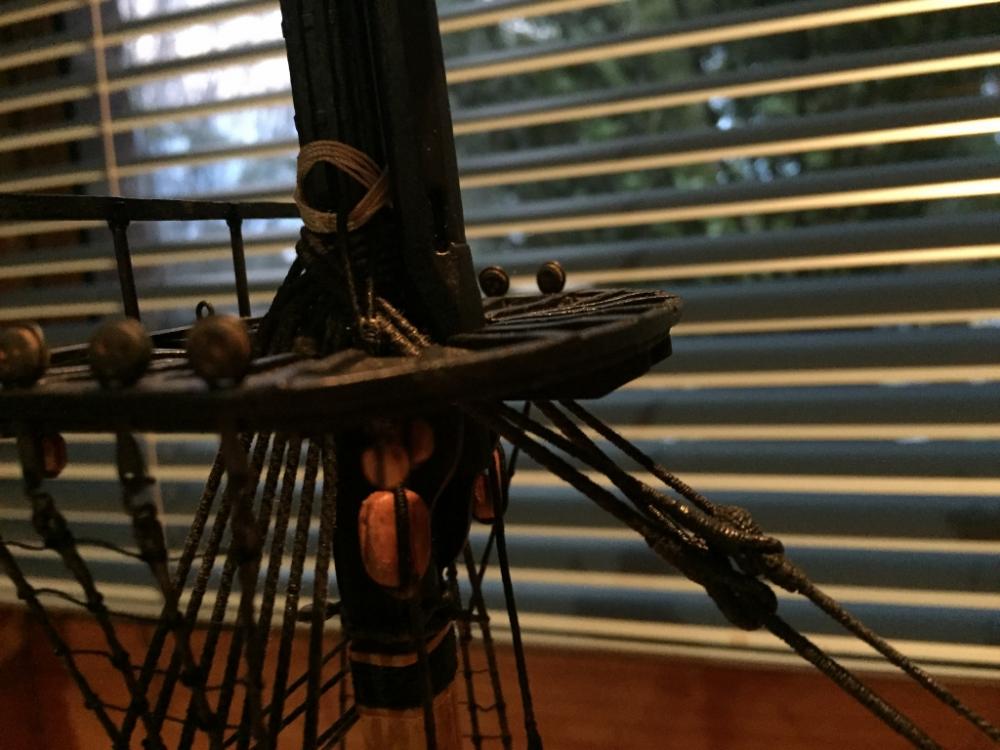
I have got all the masts done and painted now. Spent today making the Jeer blocks. I am using single blocks for both the upper and lower jeers, like the replica has


.jpg.215e60e3ceeea9aa75c3d51d0878a314.jpg)
.jpg.49368af1b7ec94fdac41c9c7fcae275f.jpg)
.jpg.df621450ee6bf2d40666e28dc7d9f667.jpg)
.jpg.ac80f7d522028315d24c193e93bde9ba.jpg)
.jpg.a128ec7ce13a1adab848d0a448f4ad1e.jpg)
.jpg.072853228cf28550047254d19cad4bd4.jpg)
.jpg.f829380beabe3ef032a44d7521c262af.jpg)
.jpg.974240020766147e242d9eb41414b8e4.jpg)
.jpg.de532130148b5b0d8c7dc7fe3e41aecd.jpg)
.jpg.00284bbfcd419f465f482a5e5b1fa1cb.jpg)
.jpg.93dcb468c0ceabaa0a98d54464963da8.jpg)
.jpg.7d7ec9aee17bfc3b56b1c2df95edf4d7.jpg)
.jpg.9e1079a8d049d6bc0eb9f1f2c7e173f3.jpg)