HOLIDAY DONATION DRIVE - SUPPORT MSW - DO YOUR PART TO KEEP THIS GREAT FORUM GOING!
×
.jpg.f4fa790b1fa2f0e00e3d149ed7bdd37c.jpg)

shipaholic
-
Posts
540 -
Joined
-
Last visited
Content Type
Profiles
Forums
Gallery
Events
Everything posted by shipaholic
-
 Hi KJ now is the time to consider one small modification, that’s if you want to. This Occre model does not have a deck camber, as all ships do. It’s very simple just glue an extra strip of wood on top of the deck supports and sand to a curvature before fitting. Don’t worry about the lower deck because you can’t see that except through the hatches.
 -
Thanks, and feel free to ask anything
-
Welcome KJ, good to see another Aussie on here, I will watch your progress on the Endeavour with interest
-
Hi Marty, I will follow your build with interest Cheers Steve
-
Hi Dave Nice work shaping the masts. But before you go any further check your scale, those masts look too tall in that last picture. Cheers Steve
-
Welcome Peter good stuff so far, I will follow your build with interest. I just checked out that new version of Endeavour on the AL website, its completely different to their old version, with many laser cut wood and metal parts it looks so much better, and I think the hull paper template idea is a great to get everything where it should be
-
Masts and the use of power tools
shipaholic replied to DaveBaxt's topic in Masting, rigging and sails
I based my masts on the drawing in Marquardt's AOTS, I believe he based his drawings on Steel's Elements of Mastmaking, Sailmaking and Rigging. Below is a photo from my copy of Steel. The taper is complex as the masts are narrower at the bottom as well, particularly the mizzen. Steel's drawings show a lot of detail, mostly unecessary in model making but gives you good idea how the masts should look. These drawings are for a larger 36 gun warship, and I don't believe Endeavour had the iron hoops as well as woolding (according to Lees Masting and Rigging of English Ships of War). A PDF of the Steel drawing is available here https://www.hnsa.org/wp-content/uploads/2014/07/mastplate4.jpg.thumb.JPG.87f47f01bea8cdf89a9536400b089891.JPG)
-
Masts and the use of power tools
shipaholic replied to DaveBaxt's topic in Masting, rigging and sails
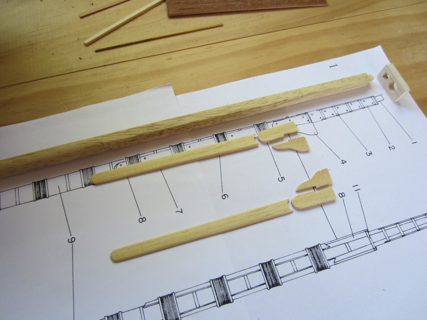
Yes I agree with Druxey. I could not see a way of doing it easily with a lathe or some othe power tool. Its just down to a lot of sanding and filing. The complex shape of the masts means it needs to be done manually and carefully, see the pic below, the mast is tapered and filed flat on both sides for the cheeks and hounds to sit flat. I used small sanding blocks to do the tapering and flat files to do the square section at the top, which also has to be tapered. Always refer to the plans to make sure the tapers and dimensions are correct.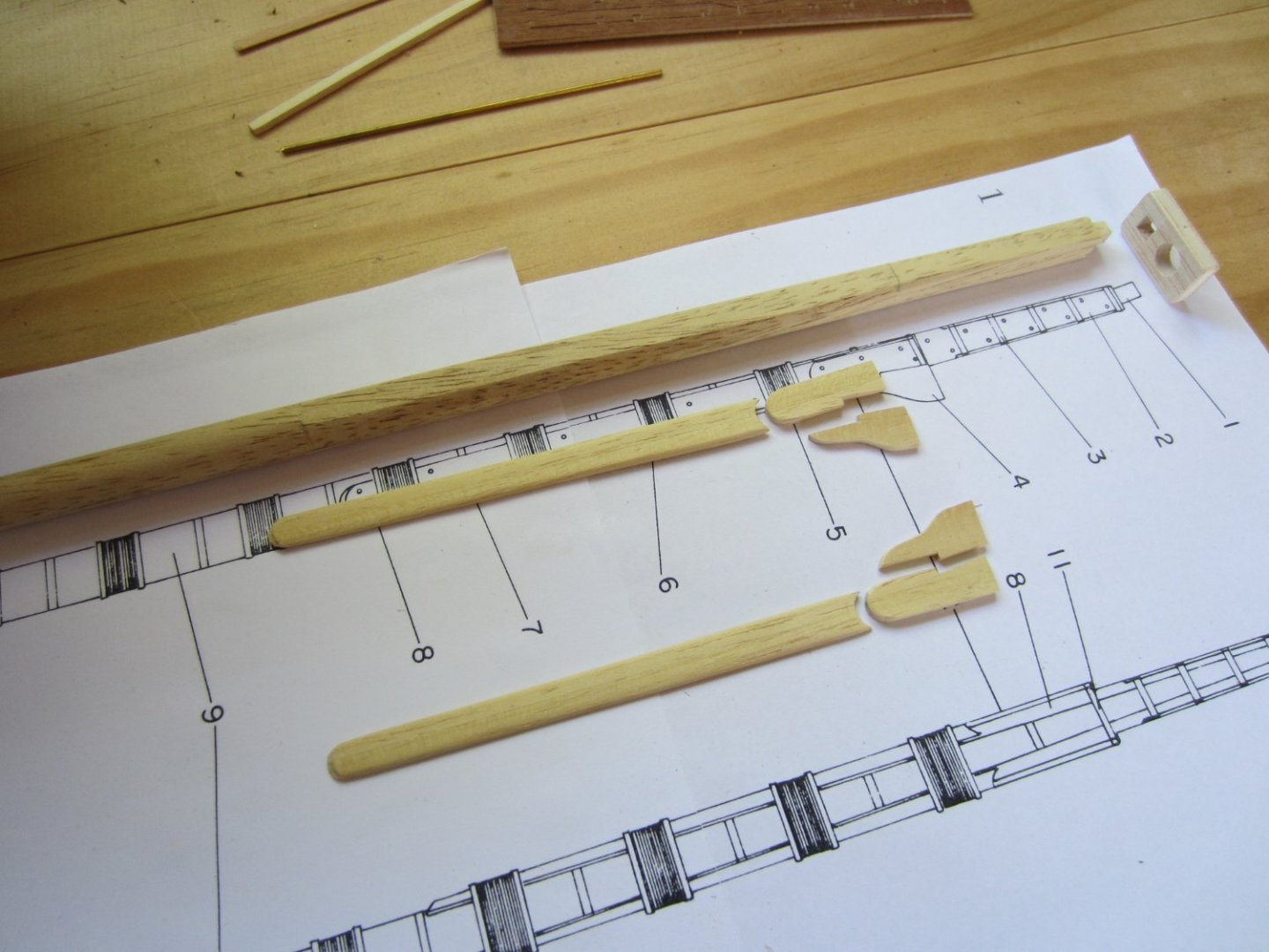
.jpg.c2b5cd1e16845b7a97c49bd4588e5345.jpg)
.jpg.cdd68c17793cc256fa2f1730d88c5054.jpg)
-
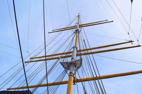
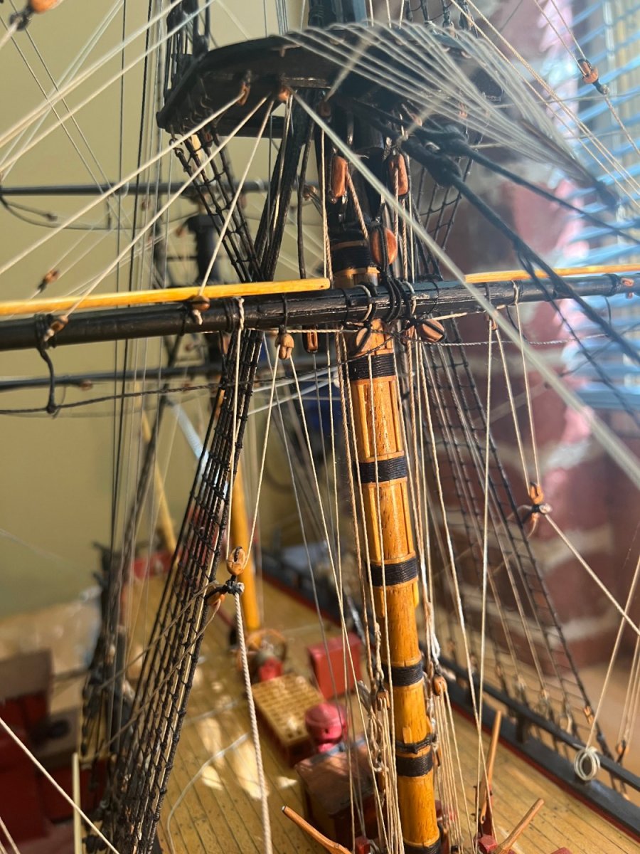
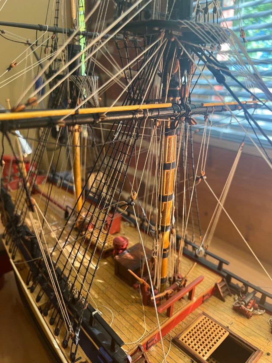
The Mary Celeste was built in 1861 so she would have had tops similar to the clippers etc of the same era such as Cutty Sark here are some pics I could find


-
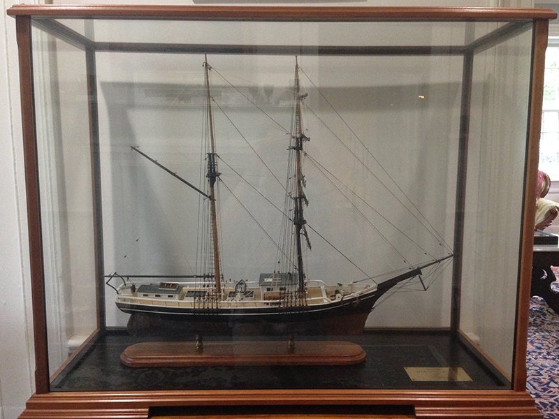
Bill, Picture of a Marie Celeste model
-
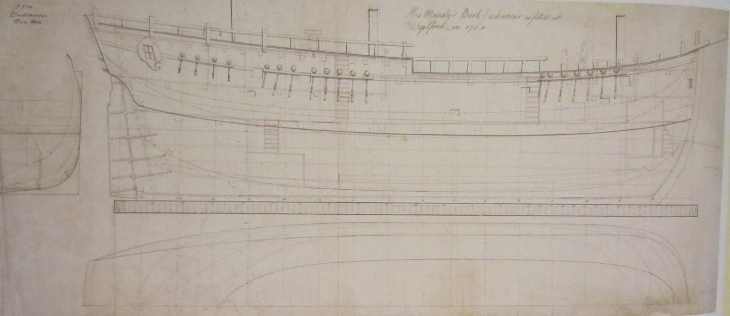
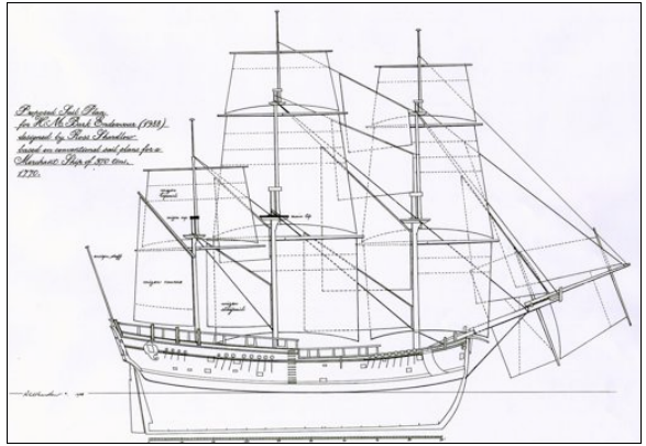
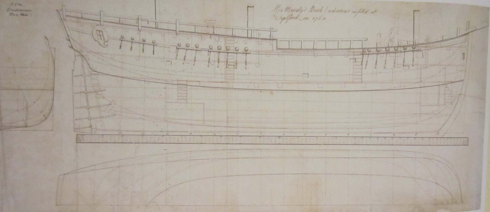
This draught is the one showing the Earl of Pembroke before refit with the proposed changes. Notice that the channels are shorter with one less deadeye on the fore and main channels
-
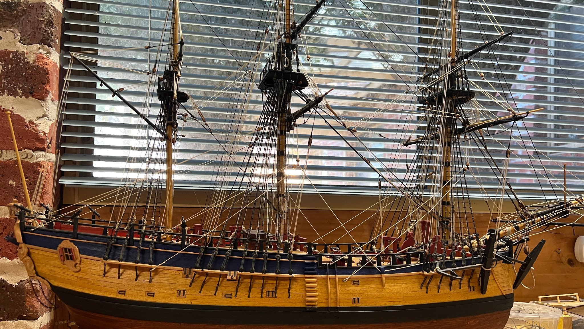
More confirmation that the mizzen channels were the same width as the main channel is indicated on this original draught, which is the one I used to base my model on. The chains are the same length from channel to the hull indicating that the main and mizzen channels are the same width. There is another draught that everyone tends to use which has a different arrangement of the rails and has shorter chains on the mizzen indicating a narrower mizzen channel, but I believe that draught is not the correct one. That draught was used as a reference by AOTS In the photo of my model it appears that the mizzen channel sits back from the mast but that is just the camera angle playing tricks with perspective. The front deadeye of each channel is in line with the rear of the mast as in the drawing Cheers
.jpg.e0cb4ca8d4750a1908d63179f7382c57.jpg)
-
Yes Dave I made my mizzen channels the same width as the fore and main ones. The mizzen shrouds are the correct distance away from the quarter deck rail. I think Caldercraft are following the drawings in the AOTS book which show much narrower mizzen channels. That book has many mistakes, Cheers Steve
.jpg.2a32564d9ac1df8338c37fd1932098d0.jpg)
-
As you say Dave the channels should all be the same width and the mizzen the correct height otherwise the mizzen shrouds will foul against the Quarter deck rail
-
Nice looking model, congrats for finishing
-
The correct height for a mizzen lower mast is that the top of the mizzen cap is level with the main mast top. Many models of Endeavour including the full size replica have a shorter mizzenmast which is not correct
-
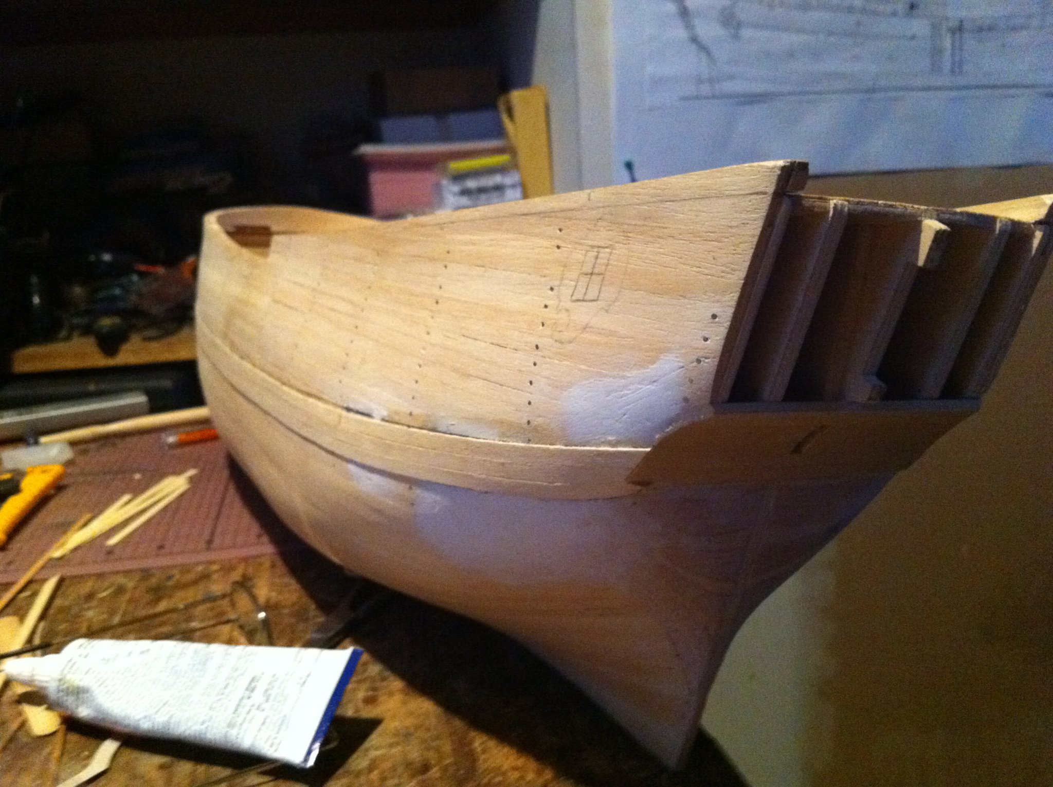
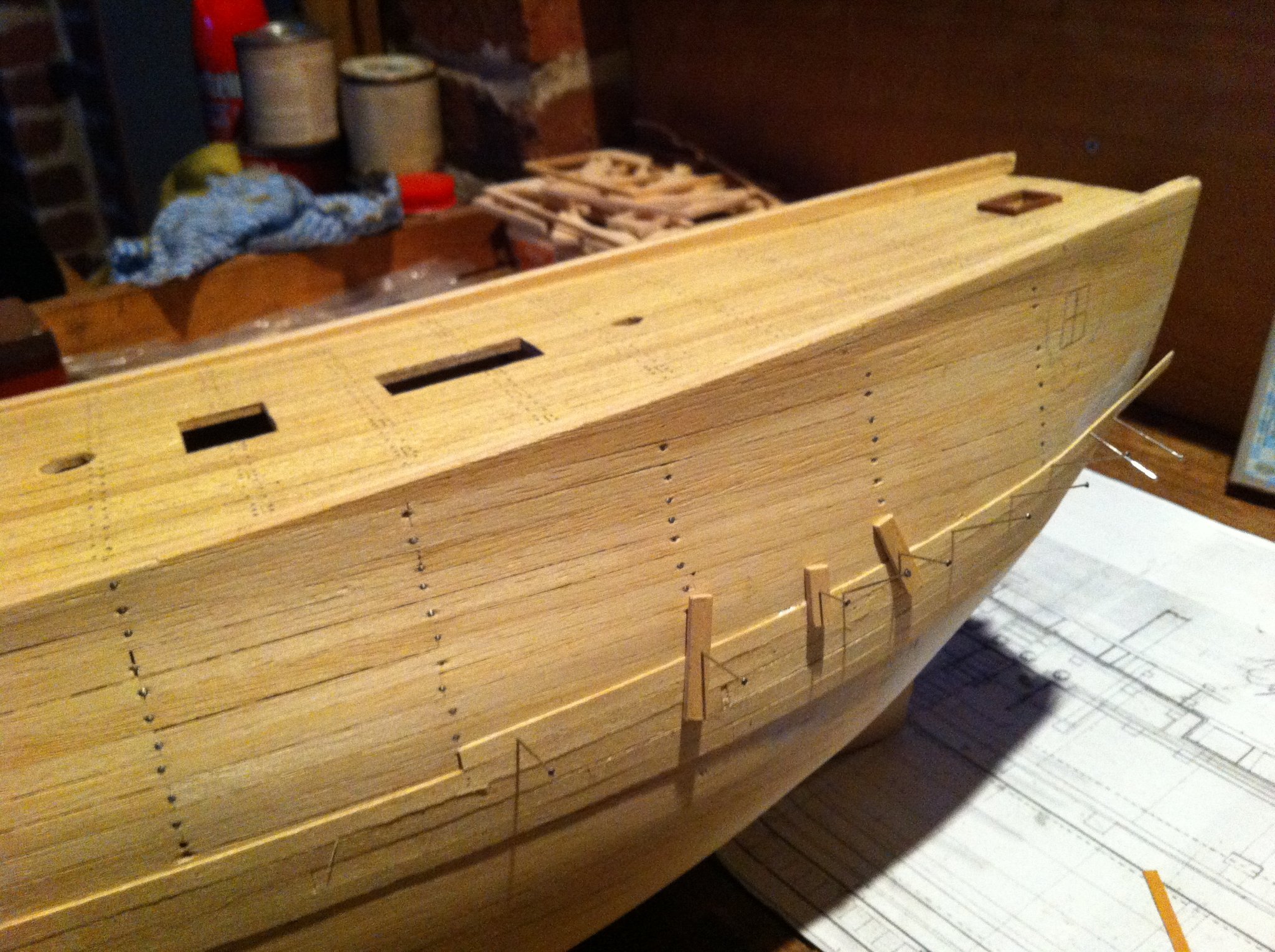
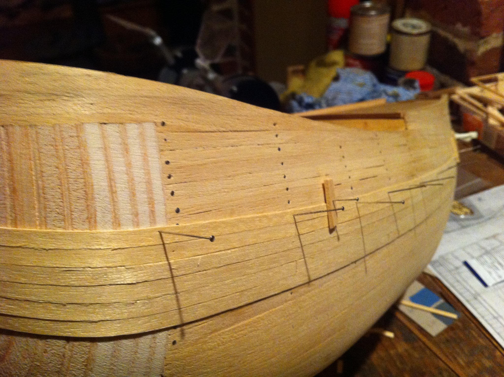
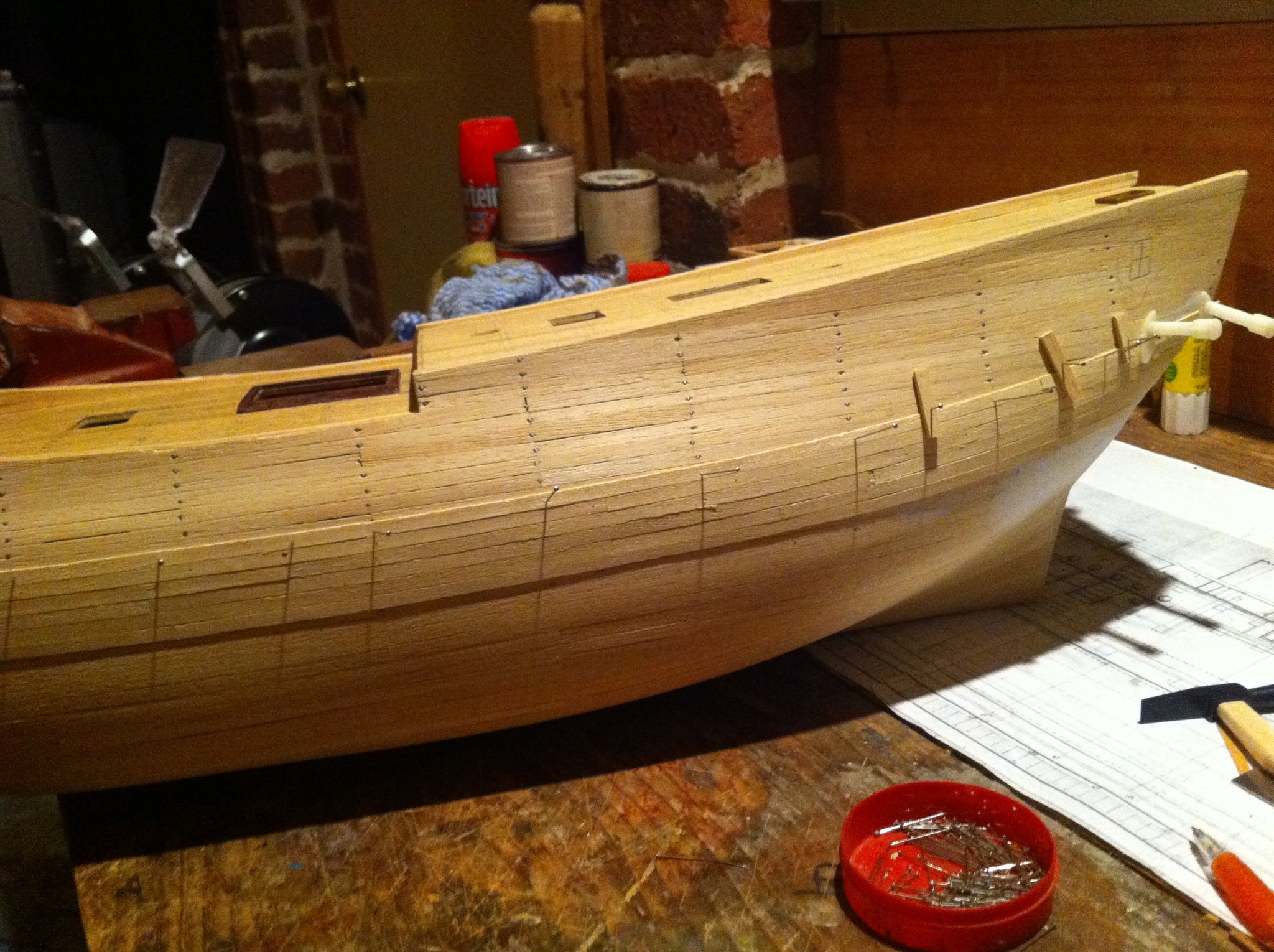
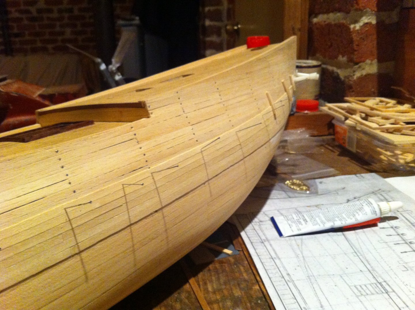
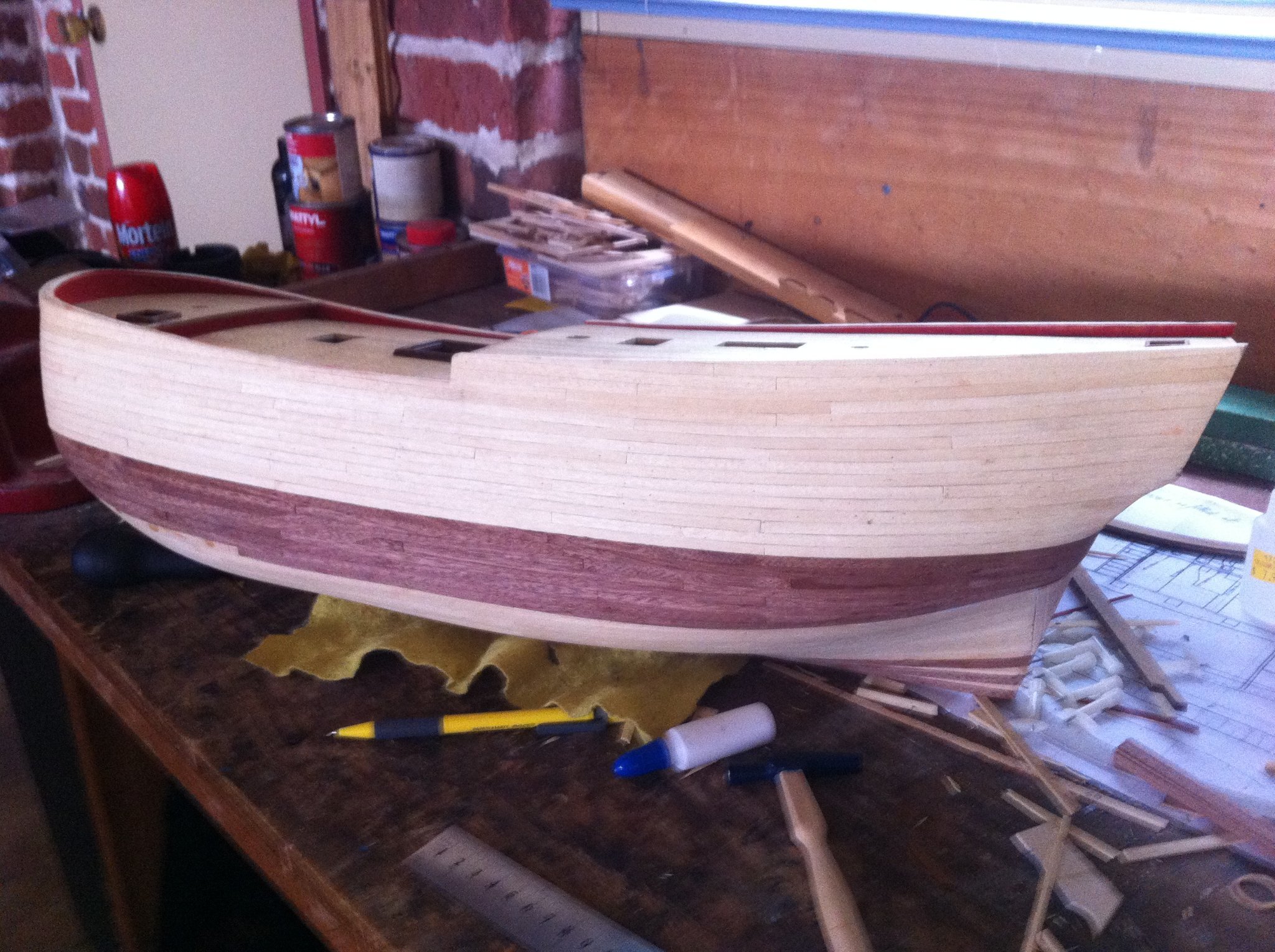
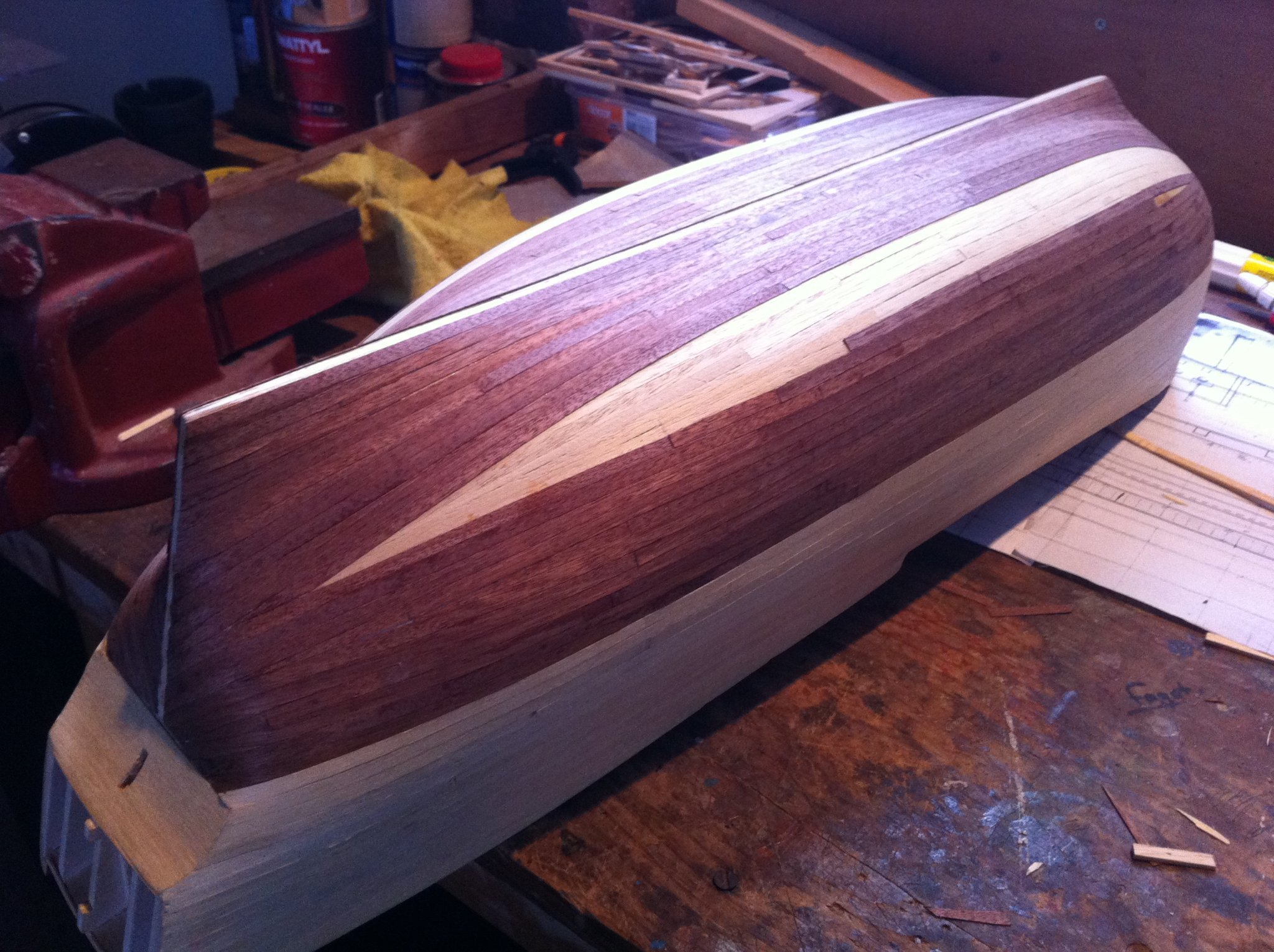
Hi Schubbe The thin planks are okay, as long as you clamp them down at regular intervals. If you notice in my pics I just used pins and scrap pieces of wood. I used PVA glue and a spot of CA glue every 30mm. I marked the position of the main wale by measuring off the original draughts (scaled to 1:52) then started the planking from the lower edge of the wale
-
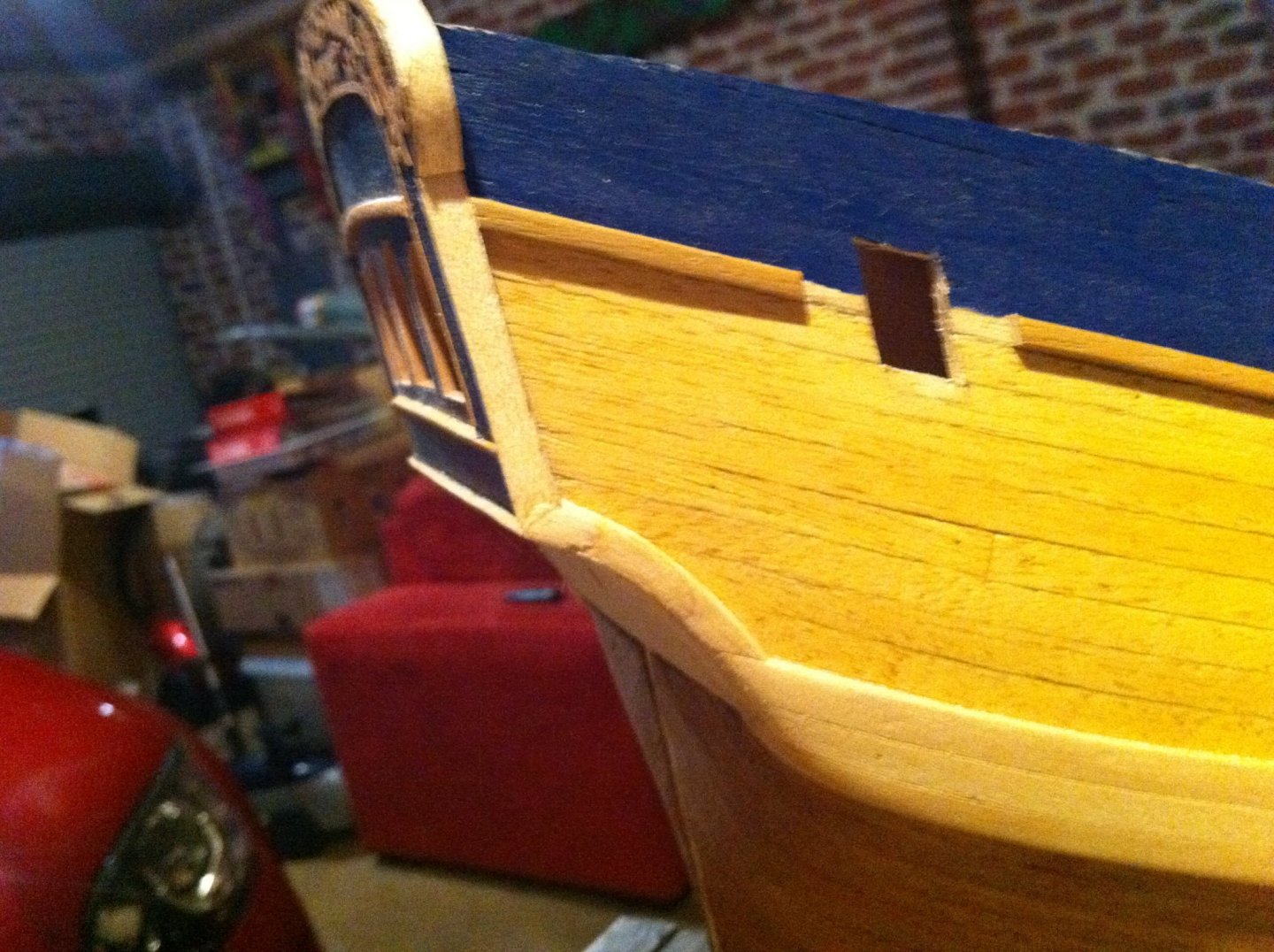
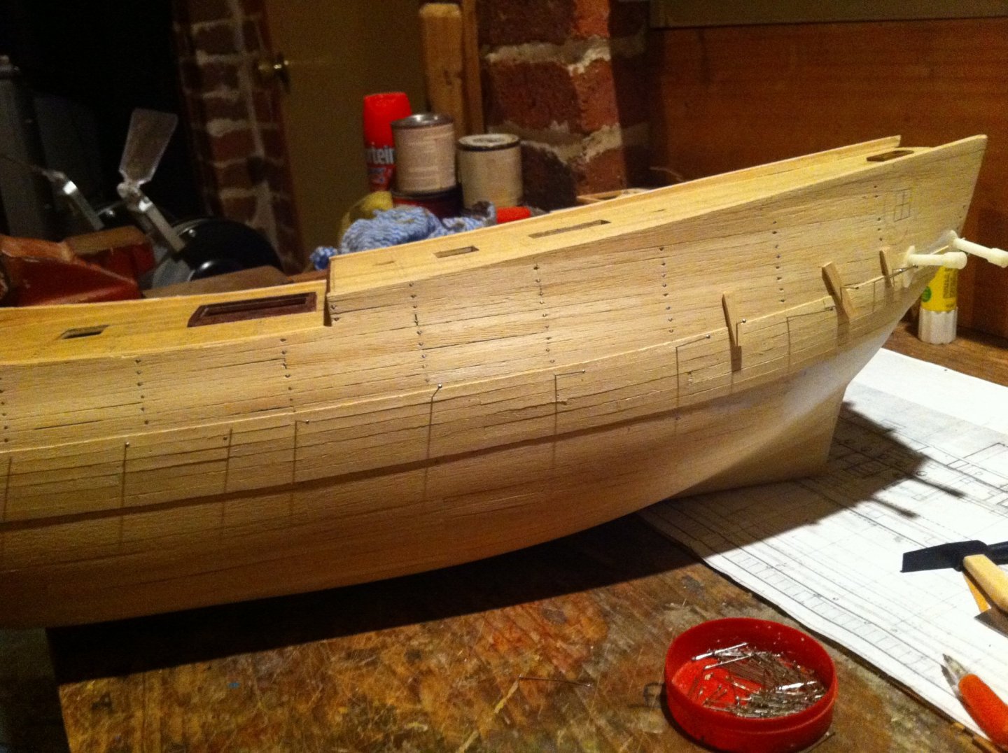
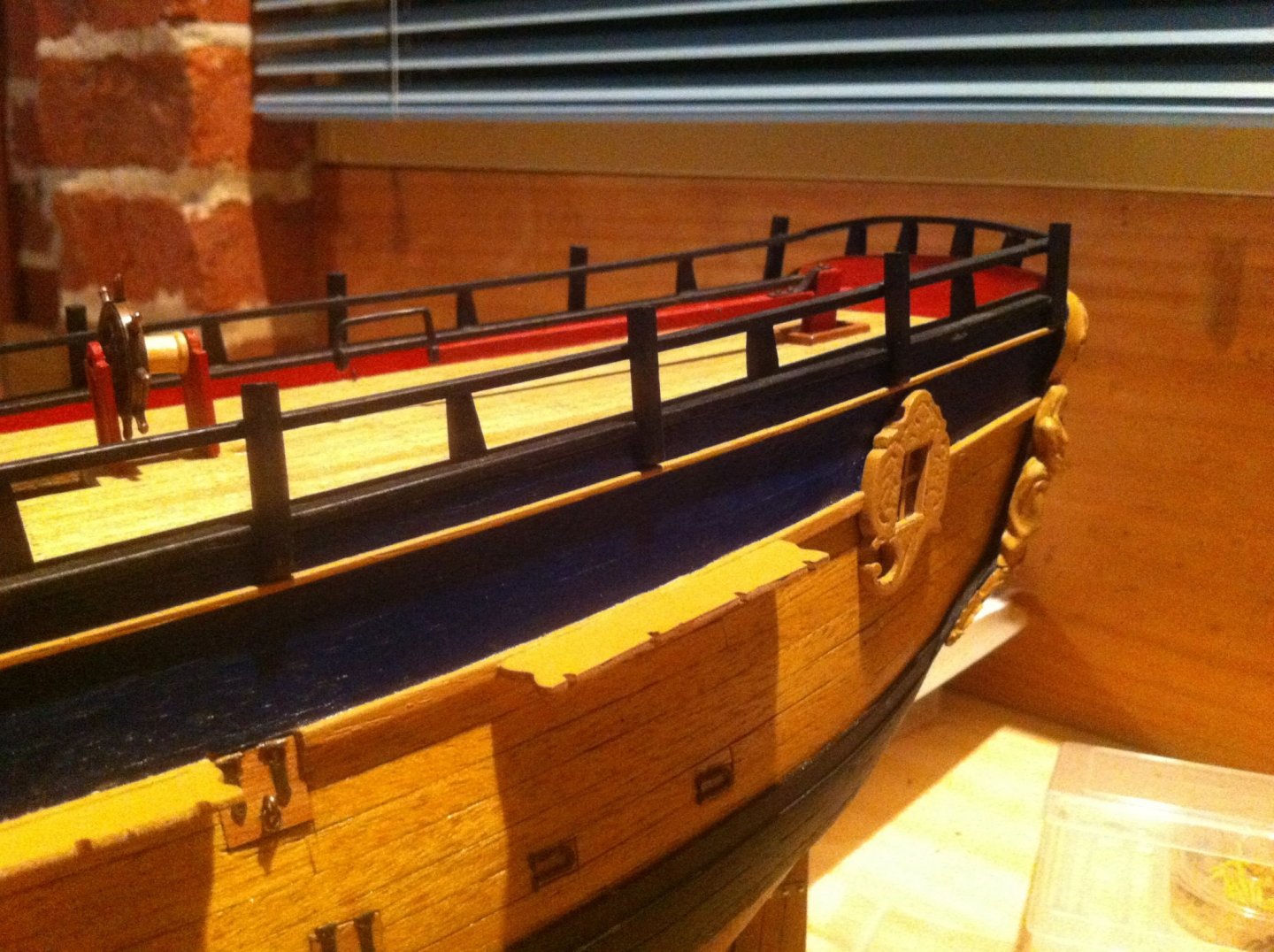
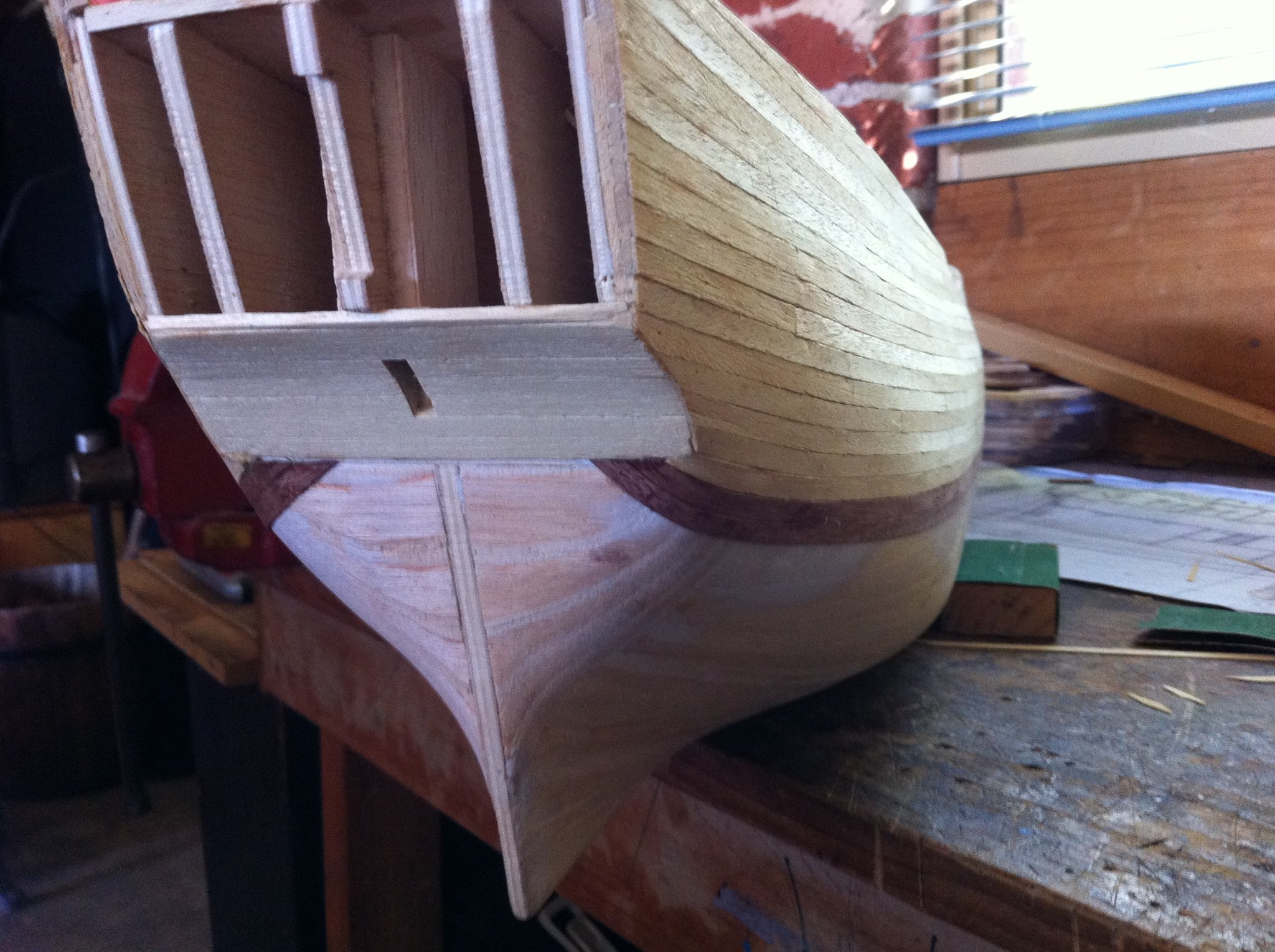
Okay Schubbe here are some more pics. The planks are thin and dont like the upward curvature, they tend to want to kink so lots of clamping to keep them flat whilst the glue sets. I used PVA with a spot of CA every 30 cm. Also here are pics of the transom I made instead of using the supplied one and how it should be at the side of the stern, so that the decorations sit properly. I later modified it a bit above the figurine
.jpg.c22936db48f11394a138a1c1f381b5c5.jpg)

(640x478).jpg.703e121cb1ee89db73ae012f8a06f638.jpg)
.jpg.88378de2ca43361787bbebdba2d42955.jpg)


.jpg.0dcc46e6dba76702a8a65f7ac3fec37b.jpg)
.jpg.ba1e9705fa7825f832c84bf37d79ca5b.jpg)
.jpg.273ab799b36b37a405670bf16d0cd39d.jpg)
.jpg.c843a5dd71b9fba3ed705f3b30695d9a.jpg)
.jpg.1d38c734d8045414a0d57ac5602e8f87.jpg)
.jpg.2f4e4f8aea46d9d6aa3b7ce8803b7b95.jpg)
.jpg.35c46bc65ebbaaf0979f8331afdad614.jpg)
.jpg.bdb1d1125458a9b8876bb172e40d7670.jpg)
-
Your build looks great so far, great attention to detail. I have built this model and like you, I made a new transom because I didn't like the shape of it nor the position of the windows. I made the windows see-through using clear plastic.
-
Funny how I'm nearly finished and I have lost interest a bit, its been 10 long years, but today i did a bit more and I will finish her in the next month or so
.jpg.f305f52e90ac0d5b4c9698c0a4f1d740.jpg)
.jpg.5d44d5ae3fae3d3da04ce76f68be3d06.jpg)
-
Wow, excellent work Eugenio, you have built it exactly how the instructions describe and it looks great. One small detail, the holes for the belaying pins should be a little larger so they sit down further on the bulge in the middle of them Cheers Steve

.JPG.464950982428e5c3a25260fa2c6b9206.JPG)


.jpg.9e50c912bbfbbfb7a0e7584bfb112ffb.jpg)
.jpg.b109694fd73e7d009c9d48e7f6acf472.jpg)