
HOLIDAY DONATION DRIVE - SUPPORT MSW - DO YOUR PART TO KEEP THIS GREAT FORUM GOING! (Only 20 donations so far - C'mon guys!)
×


robdurant
-
Posts
842 -
Joined
-
Last visited
Content Type
Profiles
Forums
Gallery
Events
Everything posted by robdurant
-
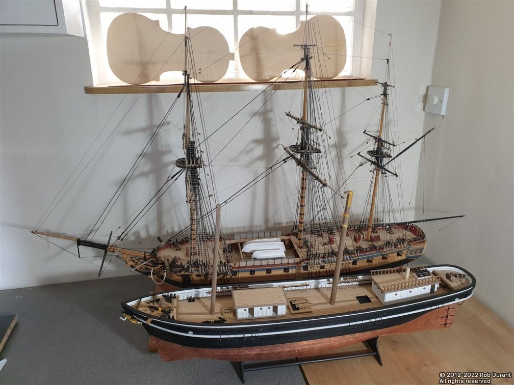
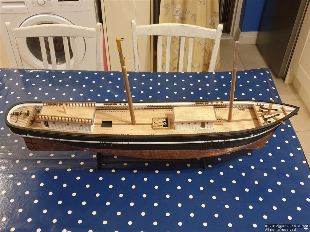
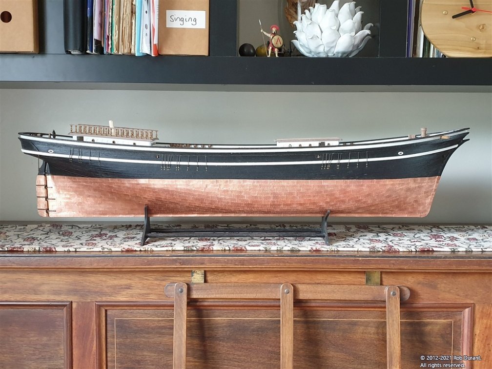
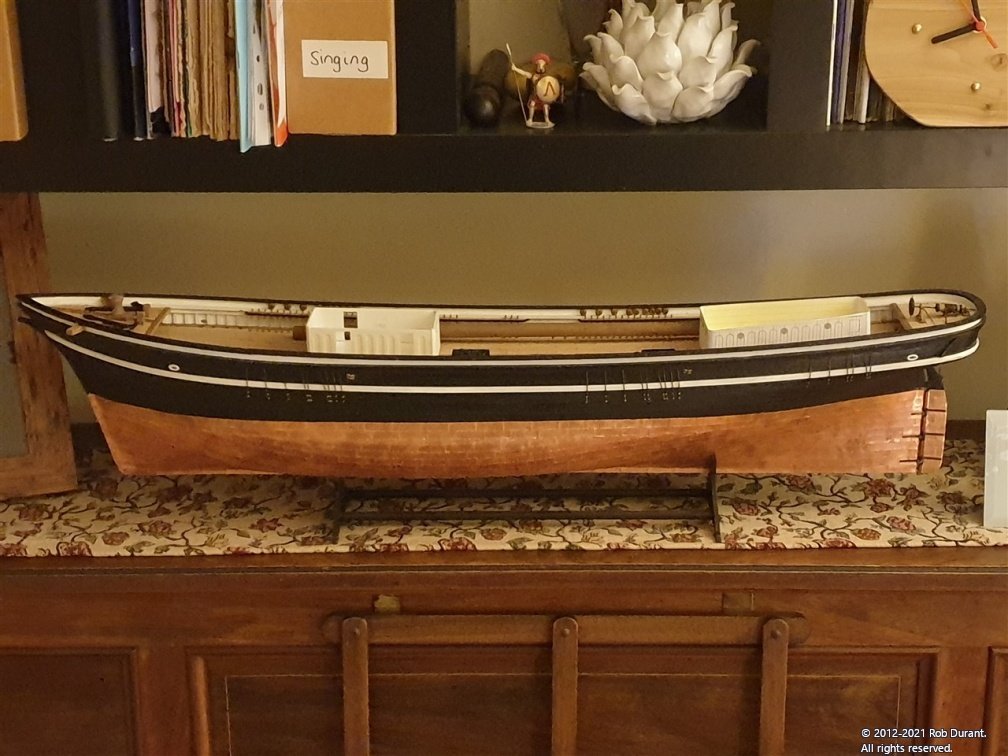
 Hi everyone, Not so much an update today as a few photos that might be of interest. I was re-making the dust cover for Ethalion, and thought I'd grab the opportunity to take some pictures of HMS Ethalion (the Caldercraft HMS Diana kit, bashed a bit), and the Barque Stefano to date... I find it fascinating to see the differences and similarities between the two... I've got a busy few weeks coming up, so there may be a bit of a pause before I'm able to give any more updates. Fear not, though. I'm keen to continue with Stefano asap Rob
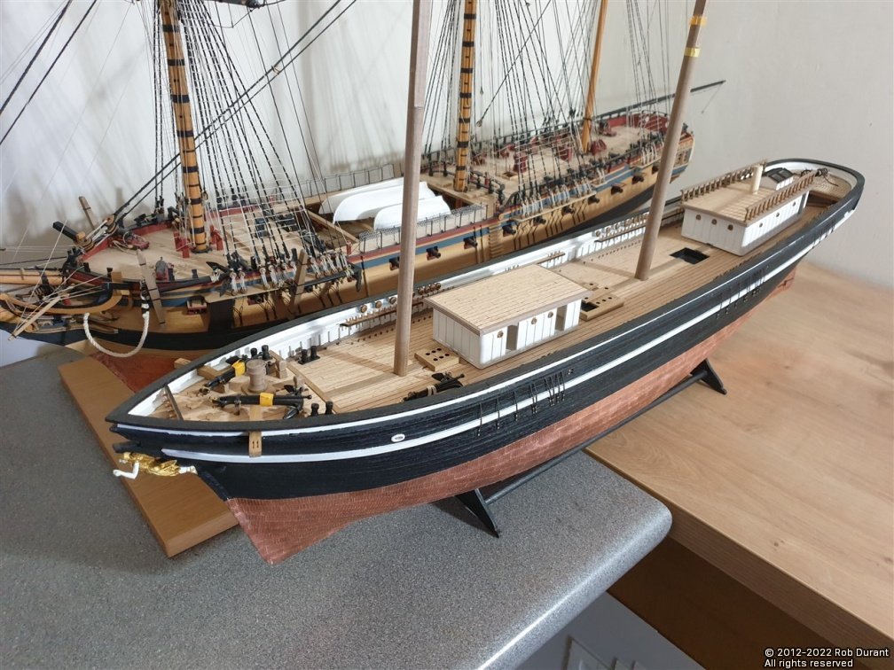
-
Thanks for your kind words. Glad you're finding the picture resizer application helpful You're very welcome.
-
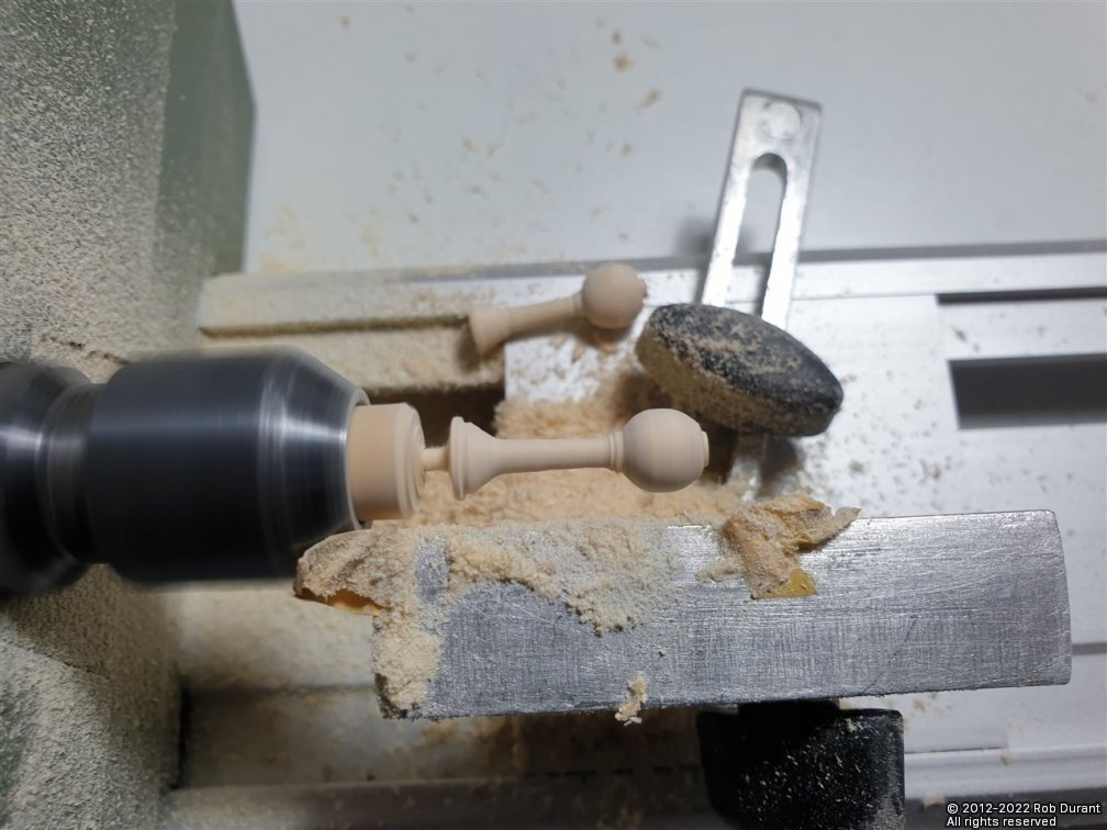
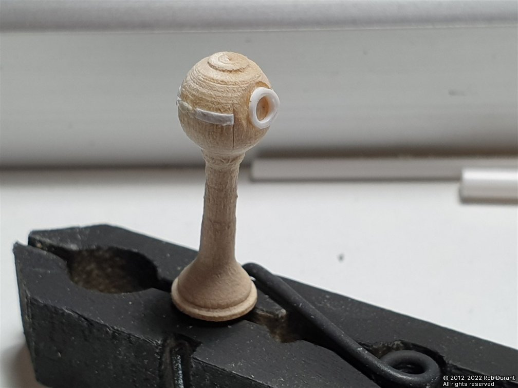
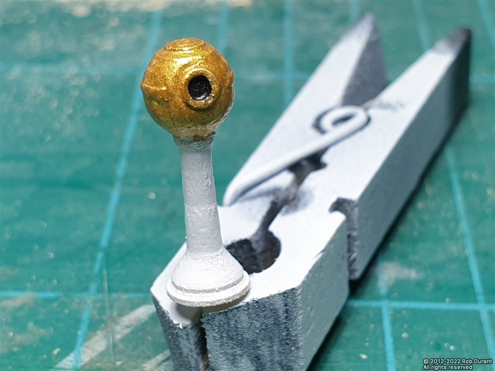
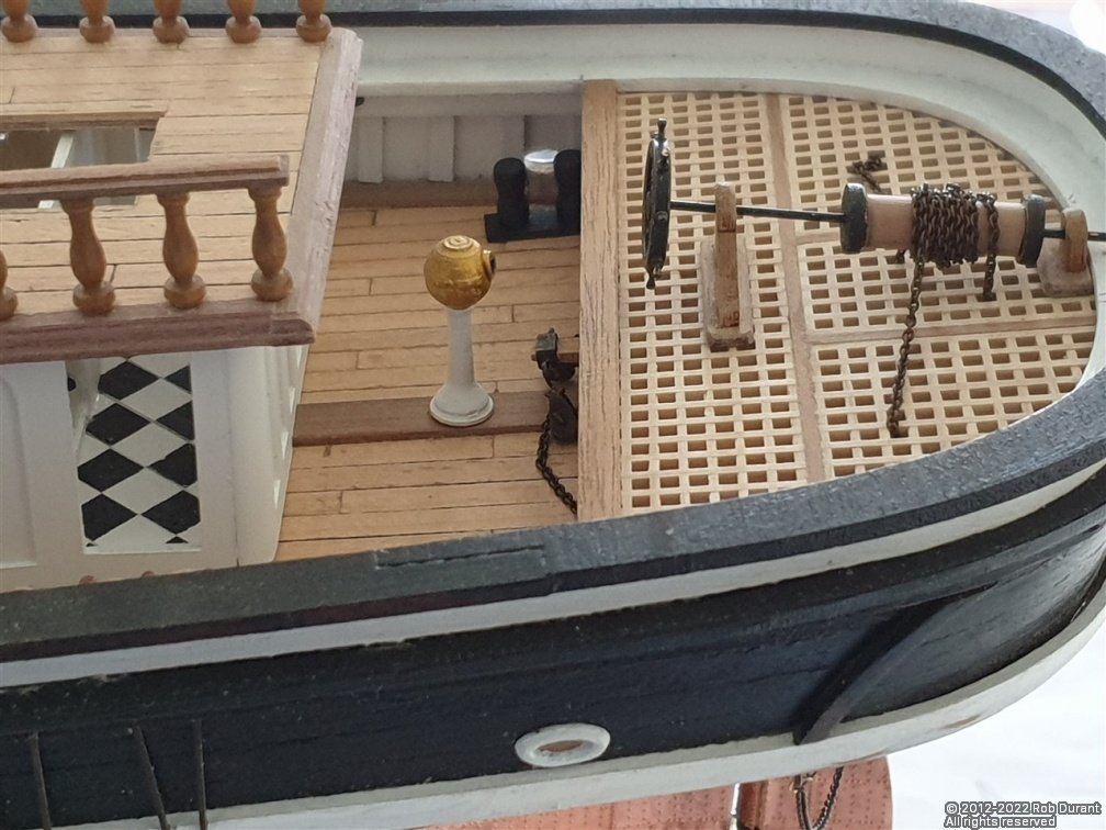
I've made the binnacle. I used the RB models binnacle for inspiration - It's really good, but made for 1:50 - too big for Stefano. Instead, I used it to work out the dimensions of a binnacle at 1:63 - it works out 23mm high - 1.4 metres at scale. I turned the main structure from 10mm lime dowel, then added a paper trim round the centre of the compass housing, a styrene viewing window and painted it. A 1.5mm rod was left on the bottom to provide a stronger joint with the model. I also glazed the skylight with transparent plastic, and used a couple of plastic battens to ensure it wouldn't fall into the model. A walnut trim was added to the inside of the skylight, and another walnut strip to the partition in the deck house where it was visible through the skylight. No pictures of that right now, but I'll try and add some later. Happy building! Rob
-
Hi Phil, She's coming along great. At that scale, those curves in the hull create a real challenge, but you're making good work of it! You're not the first person to find this a challenge. Take a look at this thread on... It's a free windows application I programmed to help get rid of those problems (which are caused by information inside the image file that your camera or phone sets when you take the picture, but web browsers don't pay attention to). All the best with your build. Rob
- 12 replies
-
- 1
-

-
- Thermopylae
- Sergal
- (and 2 more)
-
Thanks Rob.
-
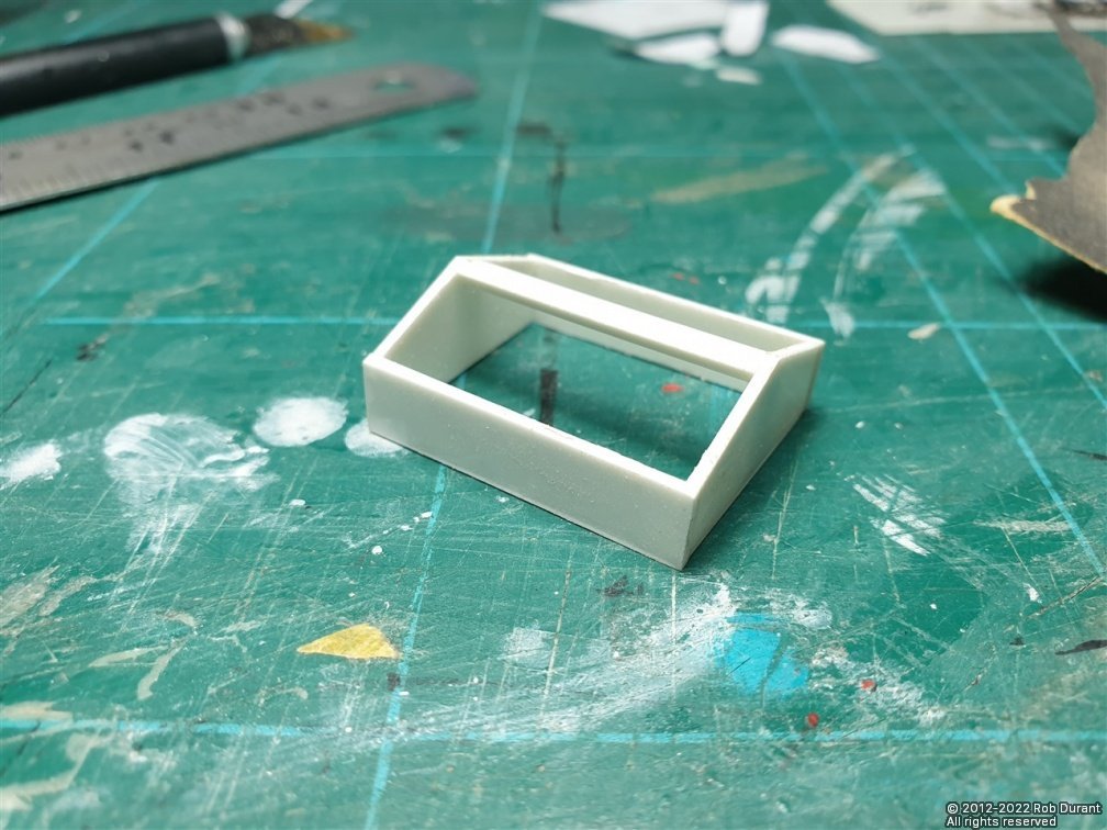
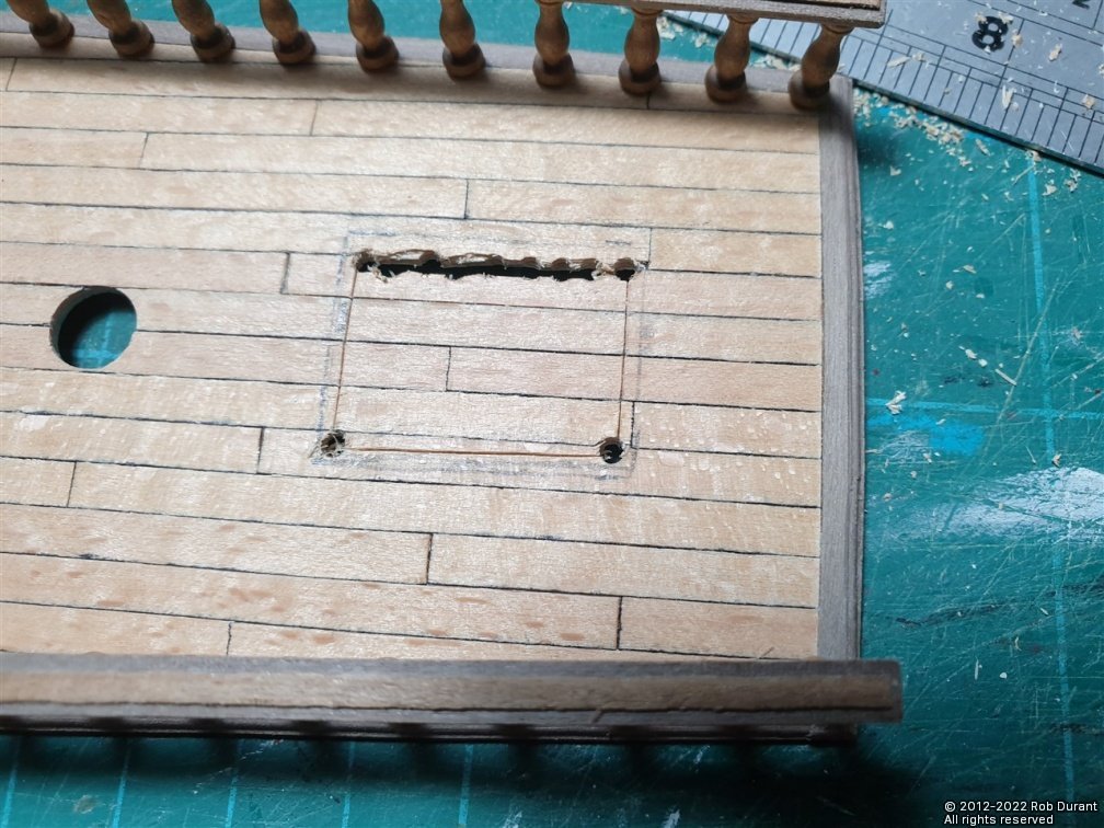
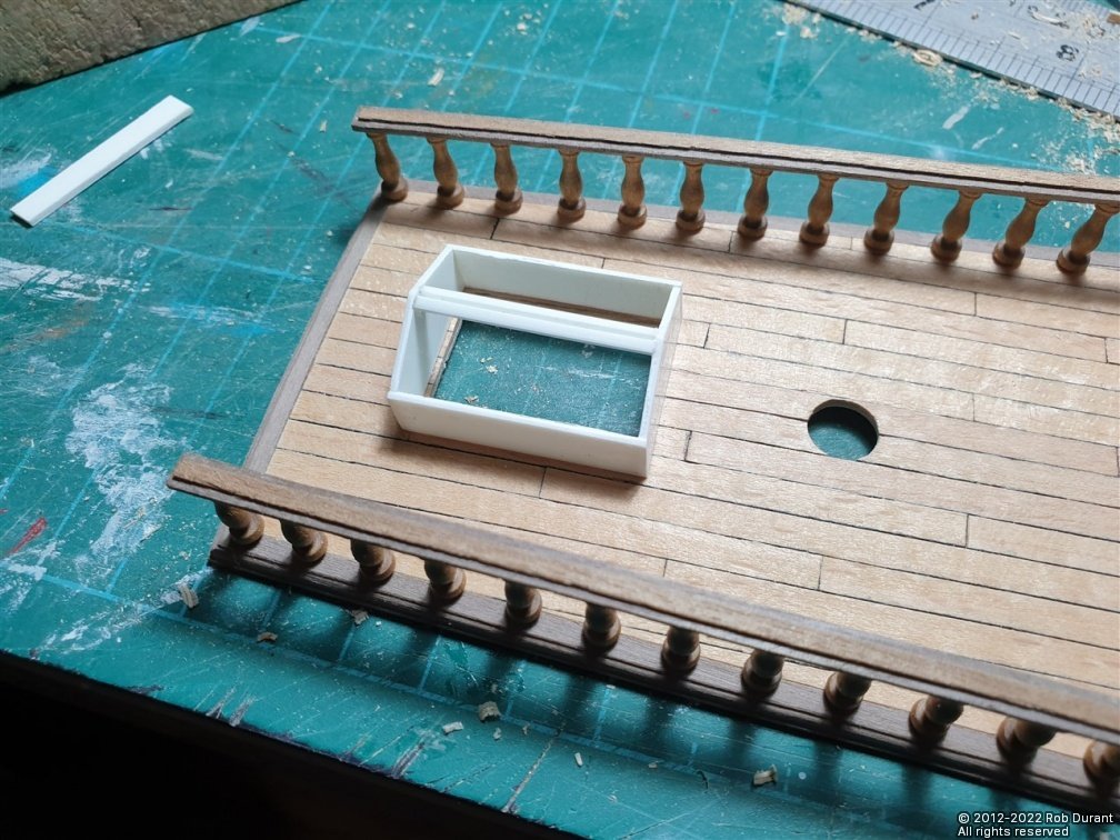
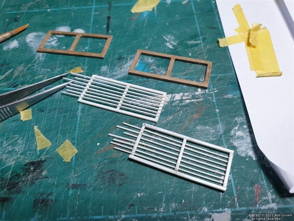
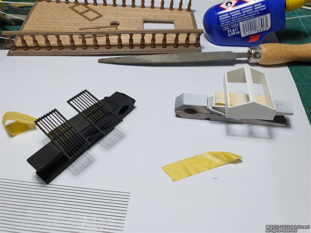
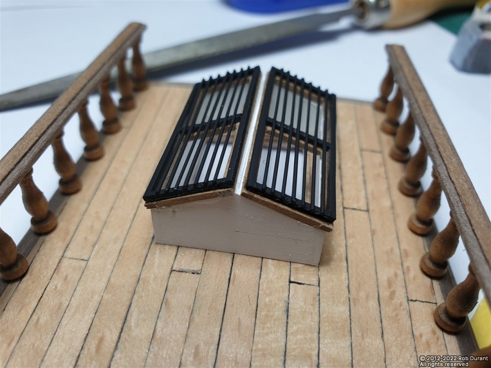
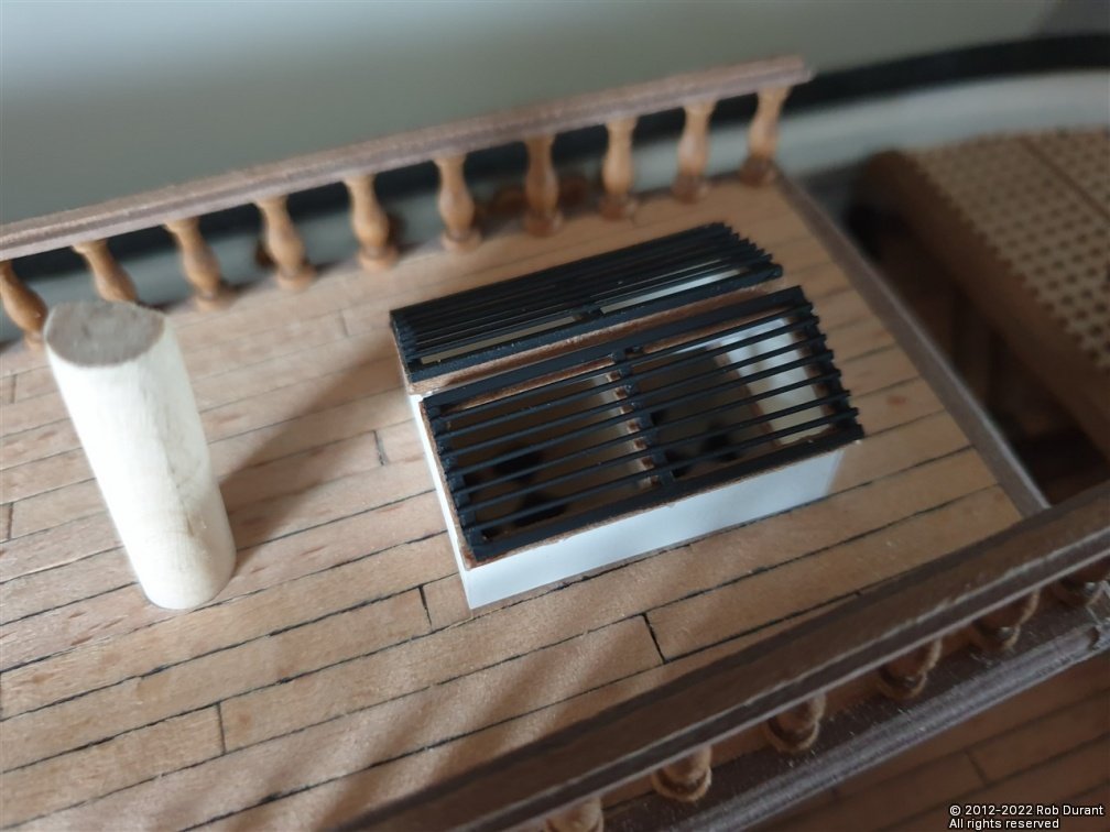
Hi all, I've had a lovely day today cracking on with Barque Stefano, and it's time for an update (in amongst being dad's taxi ). I've been continuing to work on the deck furniture, and among that are the skylight and companionway. The kit suggests these are built on balsa blocks, but I've never much liked that mode of construction, and the aft superstructure had gone so well, I was contemplating making the skylight the same way, with the 3.5mm radius corners, but when I started to draw it up in QCAD, I realised the corners were going to be well oversize for the skylight and could look a bit silly - especially when the angled top was put on with its squared off corners. Instead, I used styrene to construct the main housing of the skylight. Measurements were taken off the plans, and I made the sides to maintain the angled front and back, as per the main superstructure (which sits on the fore-and-aft angled deck. This angle turns out at approximately 3 degrees. Once constructed the skylight was placed on sandpaper that was placed on the cabin deck to sand in the curve in the deck so it could sit flush. Unlike the structures that sit on the centreline of the main deck, there is no raised king plank here, so it's an easier task. Once the size was finalised, I could mark the cut-out on the superstructure deck and drill a hole for access, then and cut it out with a coping saw (I tried chain-drilling it, but it was very heavy going, as the plywood false deck makes for a very substantial structure. I scored through the planking where I was planning to cut to avoid the planking lifting as I went. And a picture of the structure in place with the skylight hole cut. Now attention turned to the panels that form the lights on the top of the skylight. I wanted to end up with something like the effect seen on Cutty Sark as posted by Nenad here (thank you for the inspiration!): The kit shows a few upright bars, but I wanted lots of horizontal bars that were much lighter in diameter. So I made a walnut frame, and then a styrene frame to sit on top of it to simulate the metal guard. I still feel it's a little heavier than I would have liked, but it's heading in the right direction. Here they are being primed... And once the skylight itself was painted, they're put together. There are still some details to be added yet to add glazing from the inside, and to tidy up the inner edge of the superstructure deck. And here it is sat in place (but not glued on yet), showing a hint of the patterned deck below... Next up is the companionway. Thanks as always for the likes. Rob
- 286 replies
-
- 12
-
-
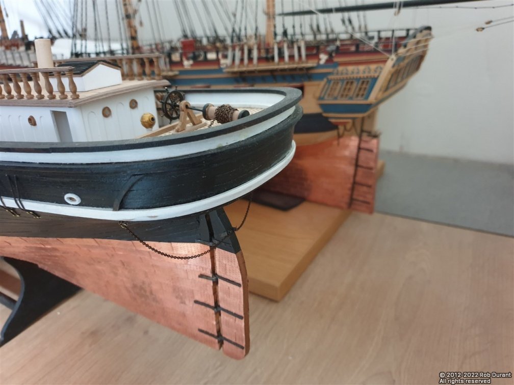
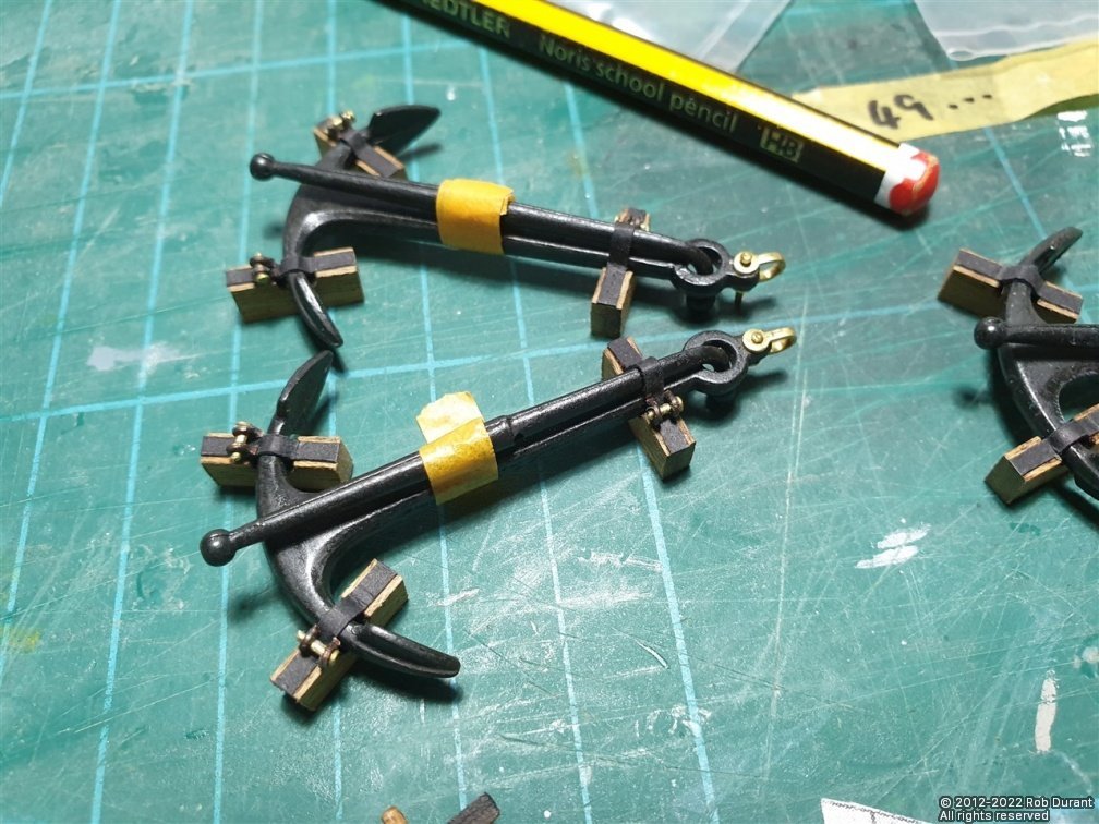
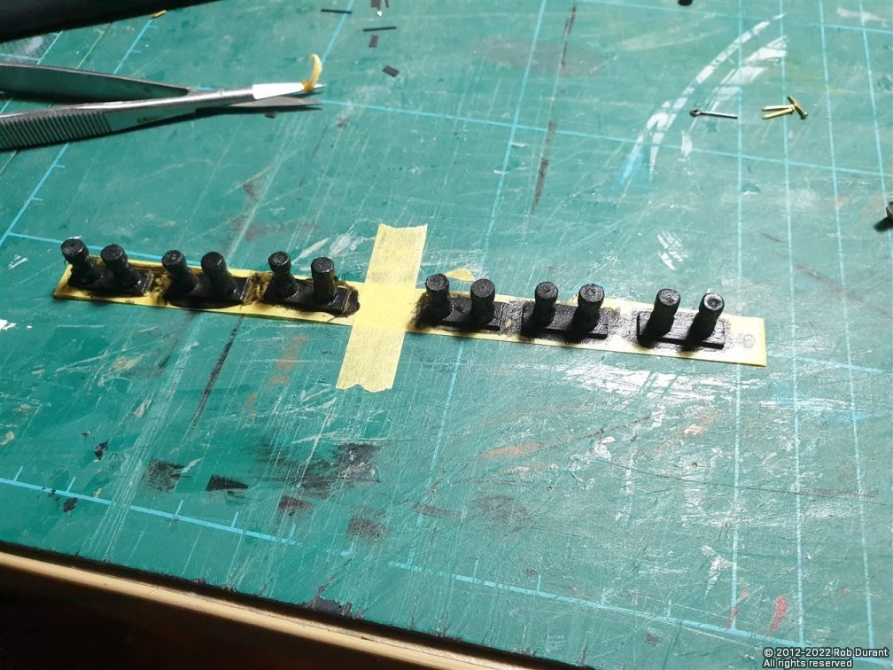
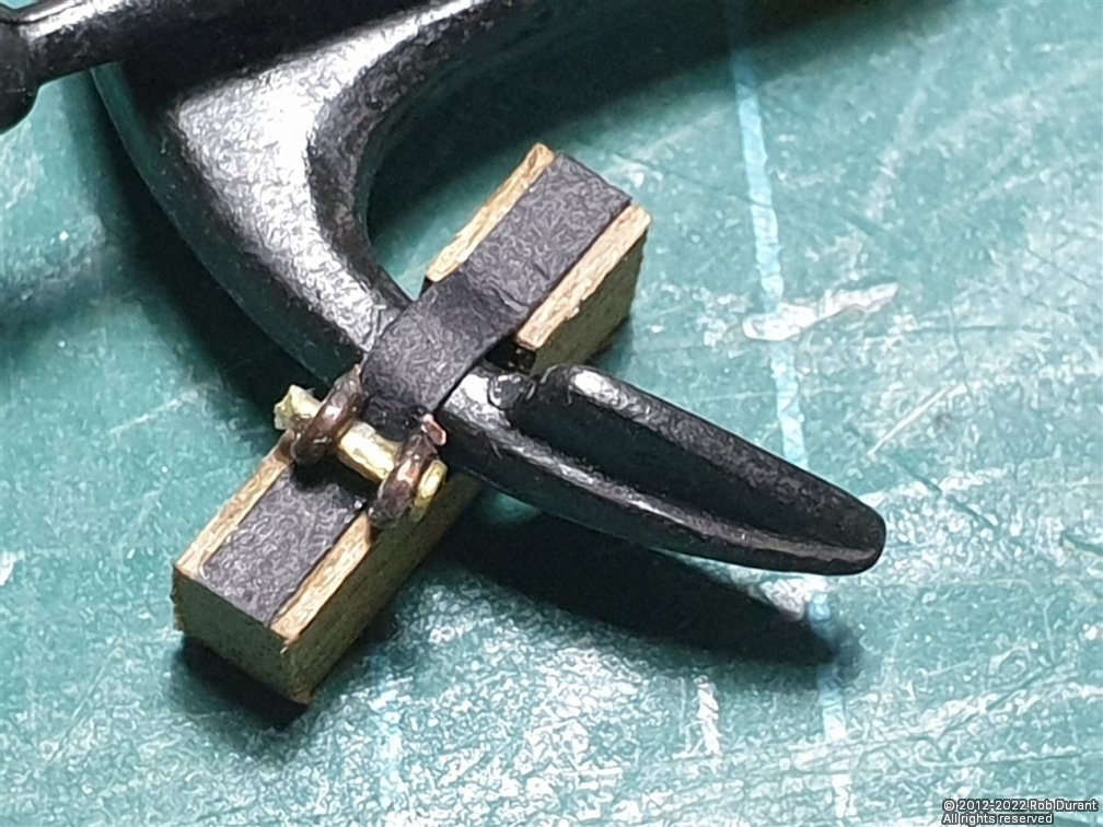
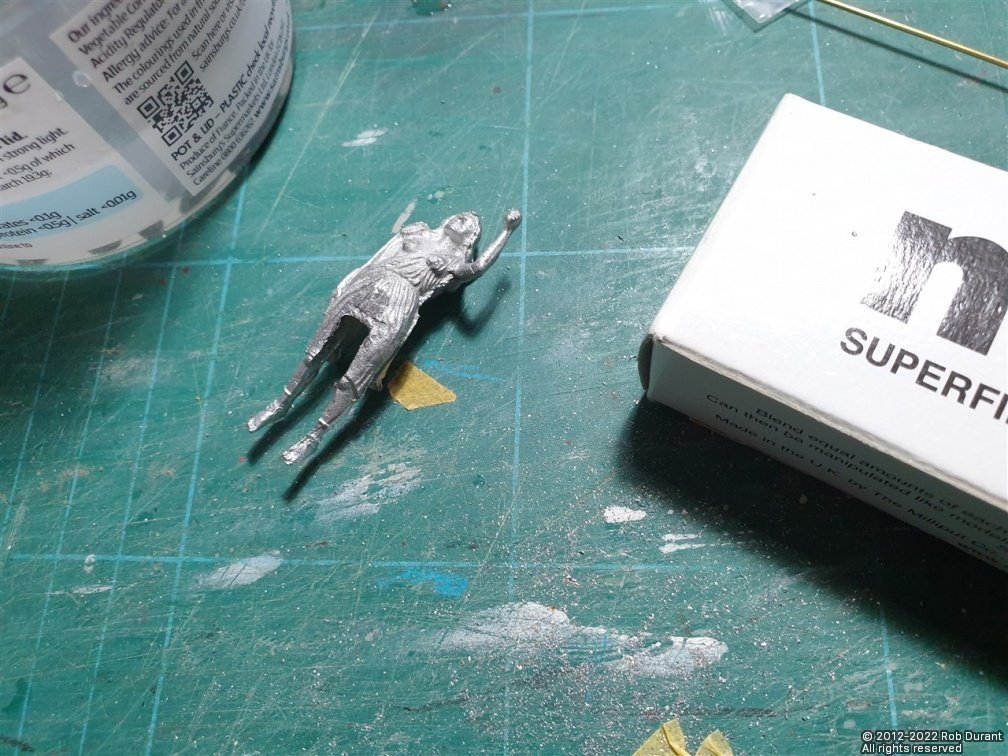
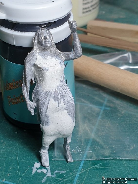
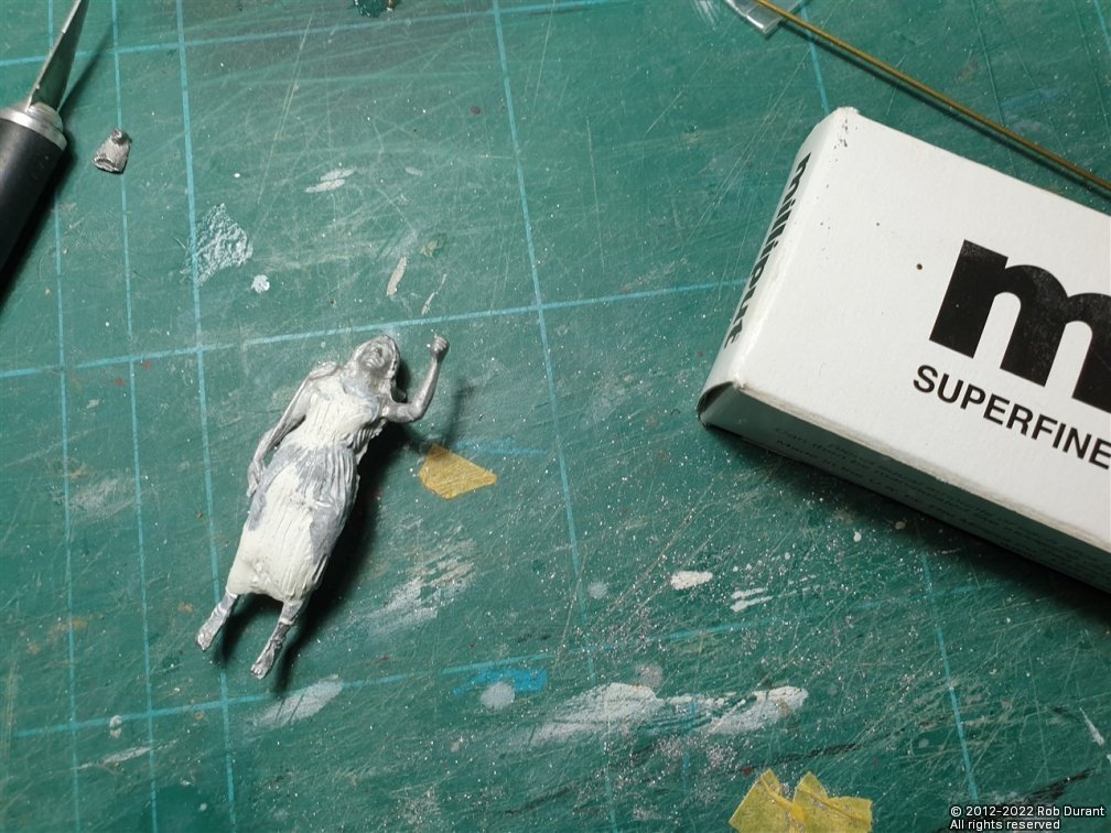
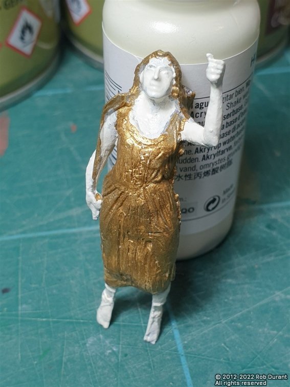
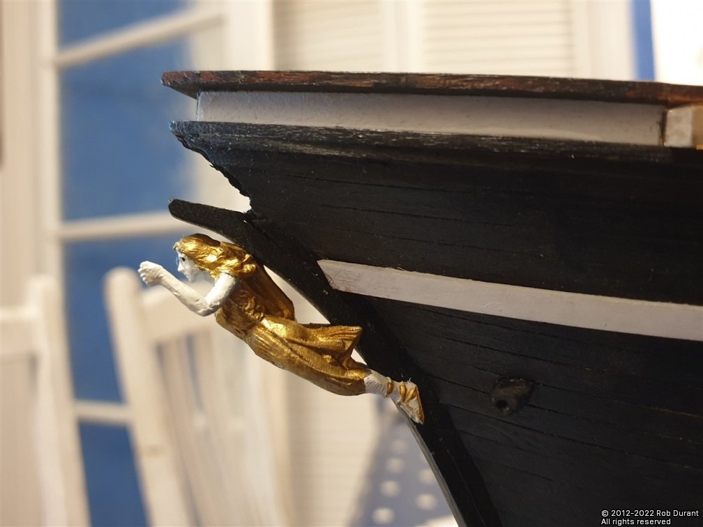
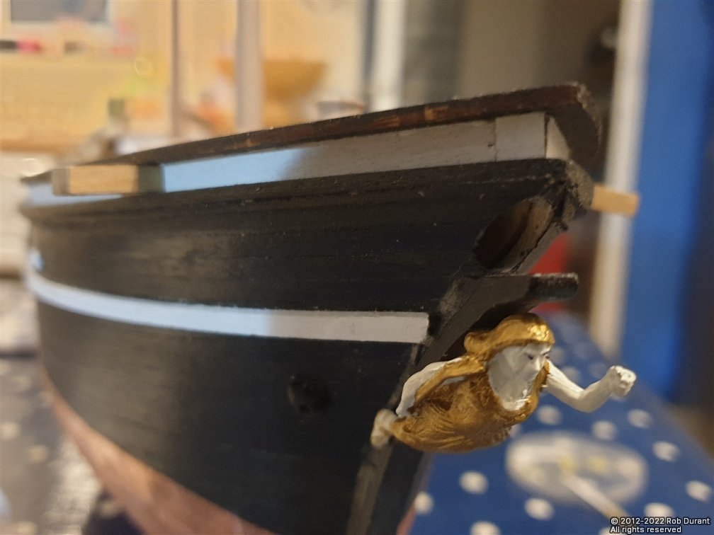
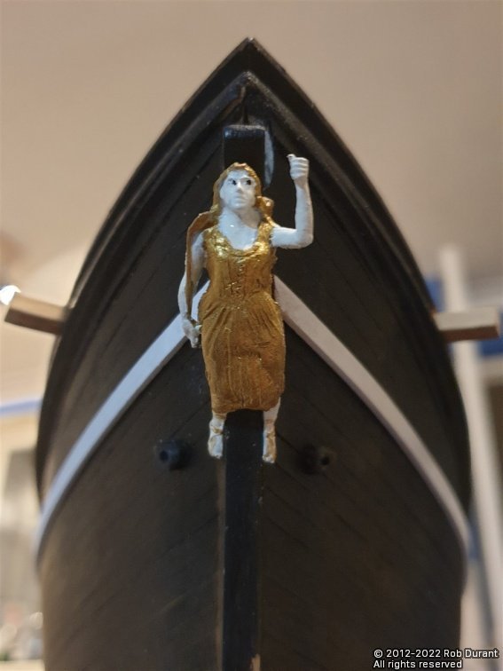
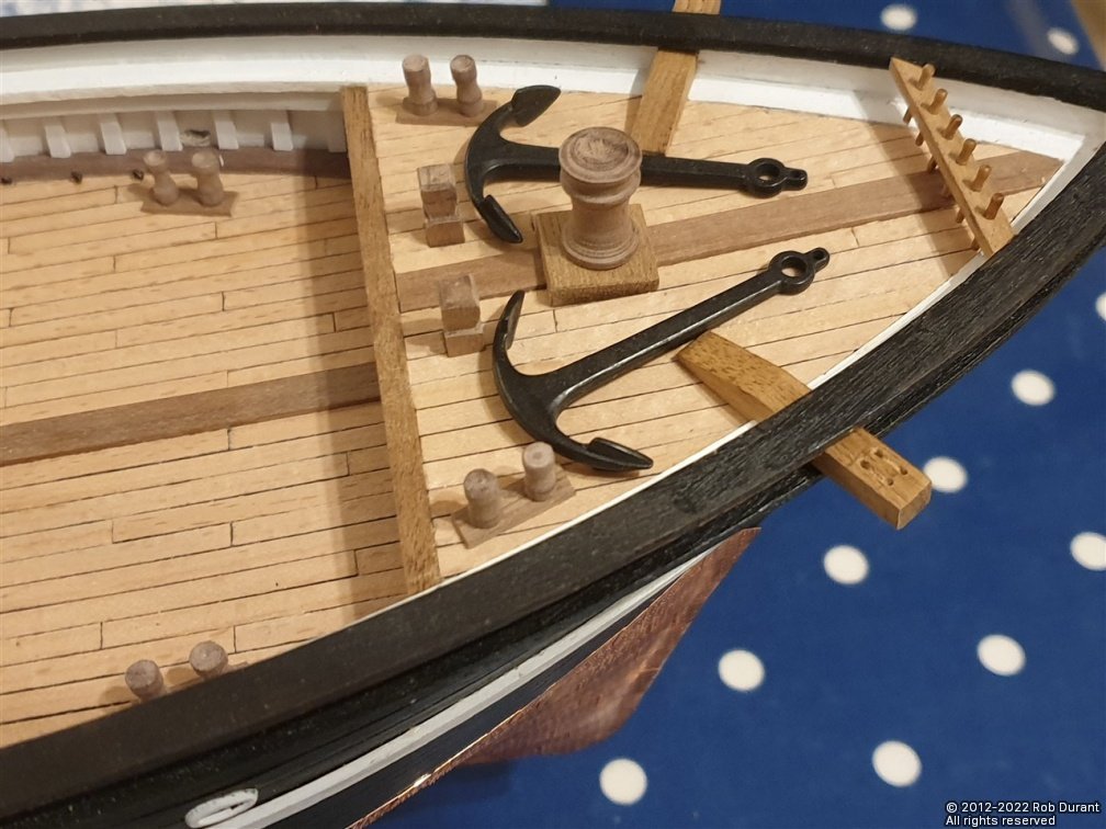
Hi all, Thanks for the likes! I've been blessed with a few evenings to work on Stefano over the past few days, so I have a little to report. With the foredeck filling up, I decided to paint the bitts matt black instead of leaving them walnut. They'll complement the anchors nicely that way. I've also put together the anchor stands with their metal parts that clamp over the anchor to stop it moving round in heavy weather. The suggestion in the kit is that the metal strap over the anchor is made from copper strip. I reverted to a tried and tested technique and used 2mm wide strips of black card. These were detailed with eyelets glued onto brass pins and cut short to represent the hinges. It's not perfect for detail, but at 1:63 it gives that suggestion of detail that approximates what's going on. I used masking tape to stop the anchor bar (proper name?) from flopping around while this was being done. The bar gets tied down with rope, and I've done this on one of the anchors - a very fiddly procedure!, but I don't have a picture yet. I'll put up a picture once they're all done. It was then that I got distracted again. I started thinking about the figurehead. The kit provides a block of wood and encourages the modeller to carve the figurehead. Thankfully, I had a figurehead left over from my HMS Ethalion based on the HMS Diana kit by Caldercraft. In that build, I scratch built a figurehead from a greek figure and a dolphin's tail... The Diana figurehead was the perfect size for Stefano with a couple of modifications: 1. The decoration where she sits on the bulkhead was cut off. 2. The tails of her dress needed to be bent outwards along with her legs to accommodate the stem and bow of the vessel. These figureheads can be purchased separately from Cornwall Model Boats, I believe. I was worried she'd get a bit cold in the Atlantic breeze, so I added a little modesty and gave her a dress that covered both shoulders, and filled in the gap where she would have sat on the Frigate's beakhead all using Fine white Milliput. Once done, the suggestion is that the whole figurehead be painted in gold, but I used a mix of Vallejo brass (which is a little toned down compared to their gold) and "Ivory" for her skin, again to tone it down a little. A pen was used for the eyes, as it's easier to control than a paintbrush! Here are some pictures of progress... As she was at the beginning of the process... Starting to add the dress... Adding dress details... And beginning to paint her... And once she was painted she was added to the bow... Overall, I feel she's a great improvement over anything I could have carved from scratch, and since she was sat in a parts box doing nothing it's a win-win situation! I'm really pleased with the way the ivory and brass colours work together, and from a distance she really makes Stefano look smart! I'm also pleased that, much like the figurehead on the plans, she has one arm outstretched. Thanks for looking in! Rob
- 286 replies
-
- 12
-
-
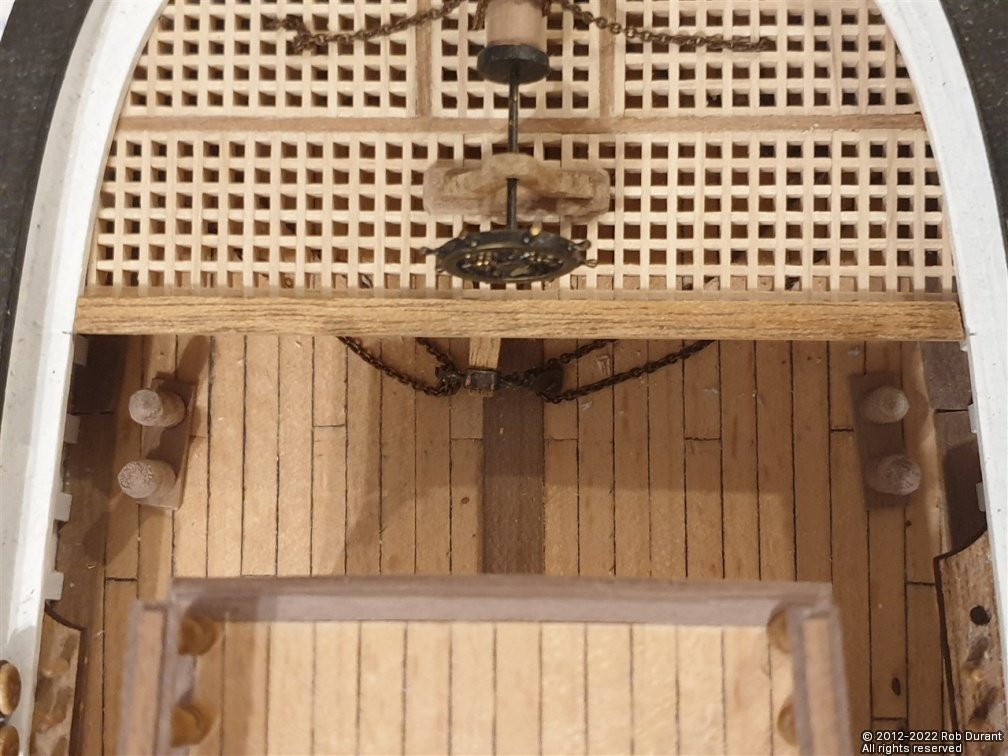
Right. Time to behave and get back to the build in order. The next step was the "remaining elements of the foredeck". Firstly, item 30 - the bitts. There are six of these, each comprising two vertical posts which are shaped from 4mm walnut dowel (I struggled to get a nice round section, so ended up using some 5mm dowel instead), and a plate made from a 15mm length of 1.5x5mm walnut strip. Using the Proxxon DB250 lathe, I was able to turn these uprights reasonable consistently. Unlike the columns on the aft cabin these will not be in a line next to each other so if they vary a little it's not such a big deal. Here's a picture of the foredeck so far, with the bitts placed roughly in position. Nothing on the foredeck is glued down yet. I've also put together the belaying pin rack (49) which can be seen at the bow. Again, I replaced the belaying pins with thinner ones. And a picture of the stern area with the bitts roughly placed in position... And finally an overview of the whole vessel so far... (I'm waiting for some 8mm dowel to make the mizzen mast). Next up in the instructions is detailing the anchor davits and working on the vertical windlass. Happy building! Rob
-
Hi Don, It's looking great! That's a lovely neat line you've got where the starboard and port planking joins up at the stern. It's probably already occurred to you, but when you get to putting the stealers in, it's worth trying to make them terminate on one of the bulkheads rather than in the gaps between. That way you shouldn't have any problems with them dipping into the hull or sinking away from the sandpaper or scraper when you're trying to get the hull smooth. Ask me how I know Looking forward to seeing your next update! Rob
-
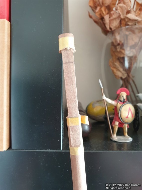
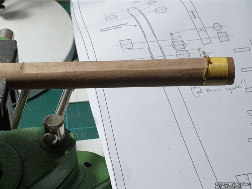
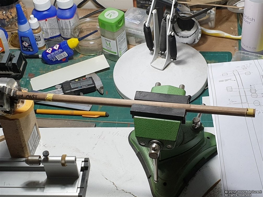
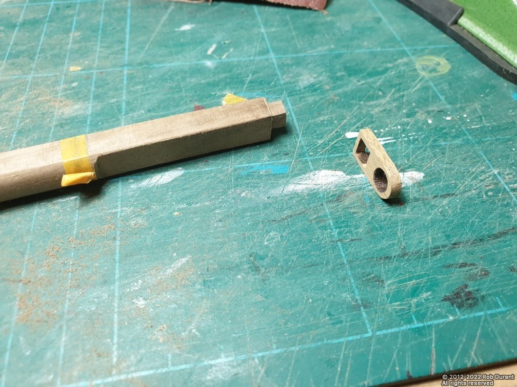
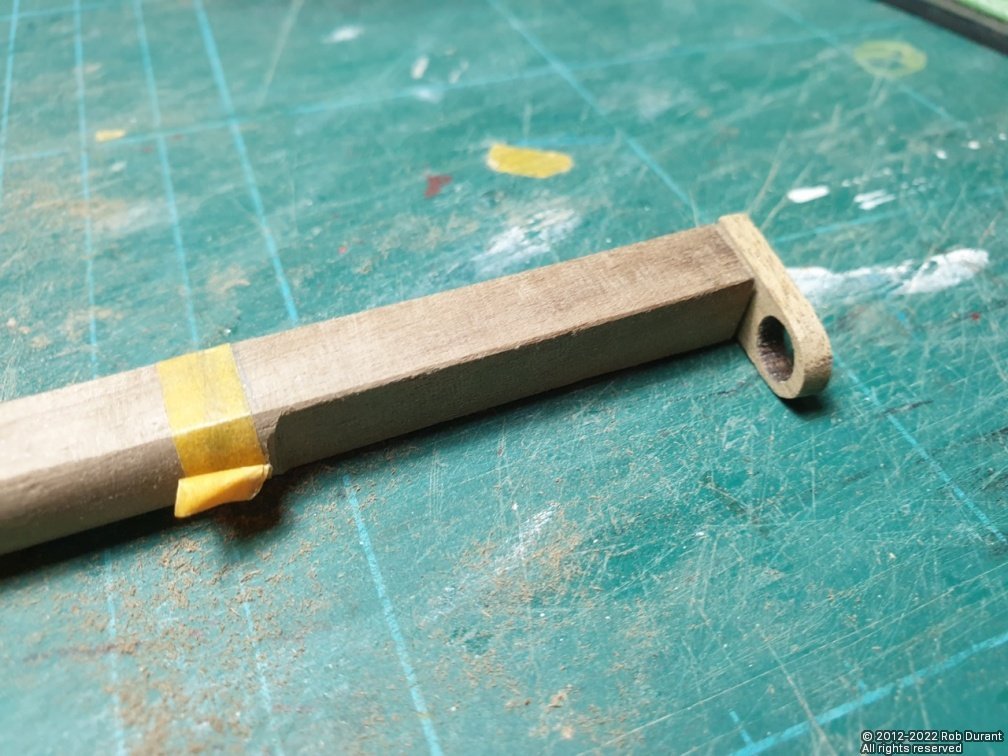
Hi, Thanks for the likes and encouragement. There's more to be done on the deck houses, but I fancied a bit of a change, so I've been working on the main mast. This is made from 12mm dowel. It narrows to just over 11mm as it gets towards the top, then there's a flat section on both sides for the top cheeks which becomes 8mm square, then becomes 5.5mm square for the last 5mm where the mast cap fits. The plans are excellent. Very clear, and with all the information you need clearly laid out in 1:1 scale. I was really impressed. Sadly the dowel was both too long, and too large a diameter for my lathe and my drill, so gently hand sanded the dowel to create the taper. In retrospect I should have created the square section at the end first, as having this taper made it harder to then create the square section. nb: You will need to leave enough diameter to ensure the square section will not have rounded corners. Pythagoras tells us that for an 8mm square, the minimum diameter will need to be the square root of 64 + 64, which comes to 11.32mm (to 2d.p!), so don't reduce the dowel beyond that. I used the lathe three jaw chuck as a means of seeing whether I'd lined the mast up at the right angle for filing the edges. It's not perfect, but it's getting fairly close to how I'd like it to be. The mast cap is a laser cut part, an I opened up the cap slot to allow it to sit horizontally rather than follow the mast's rake. I'll take a picture of it in the daytime tomorrow as the light will result in a terrible photo this evening. Rob
-
Hi Don, Looks like a solid start. Hope you won't mind if I follow along. Rob
-
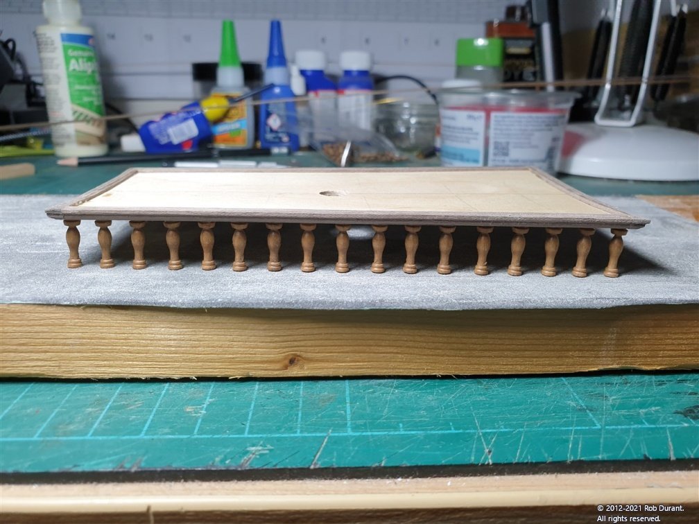
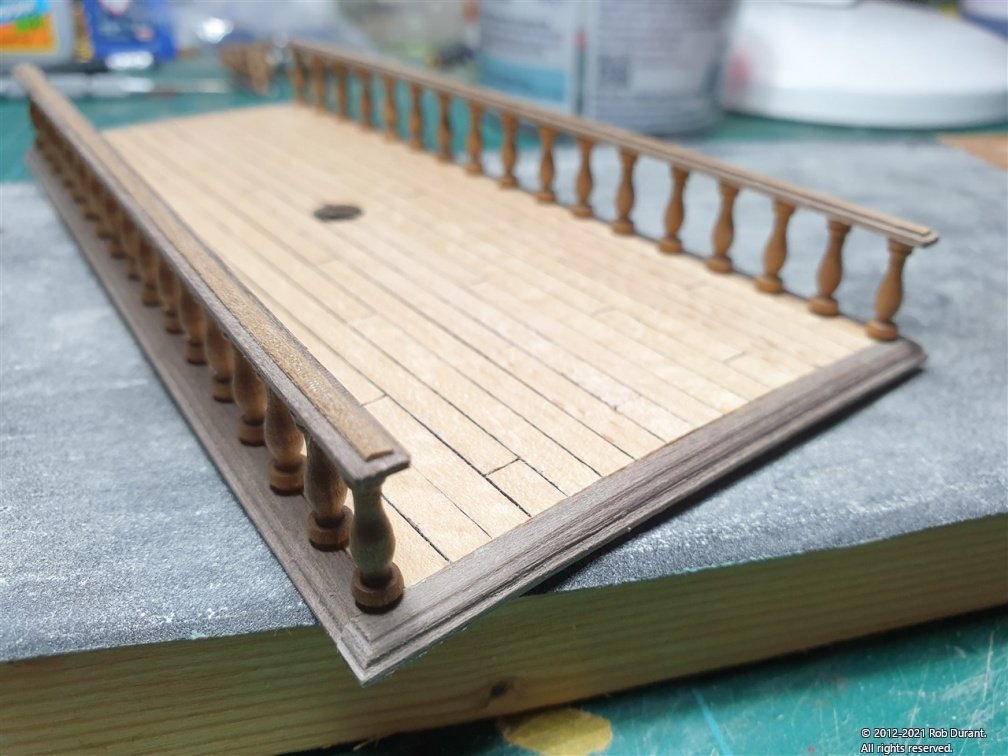
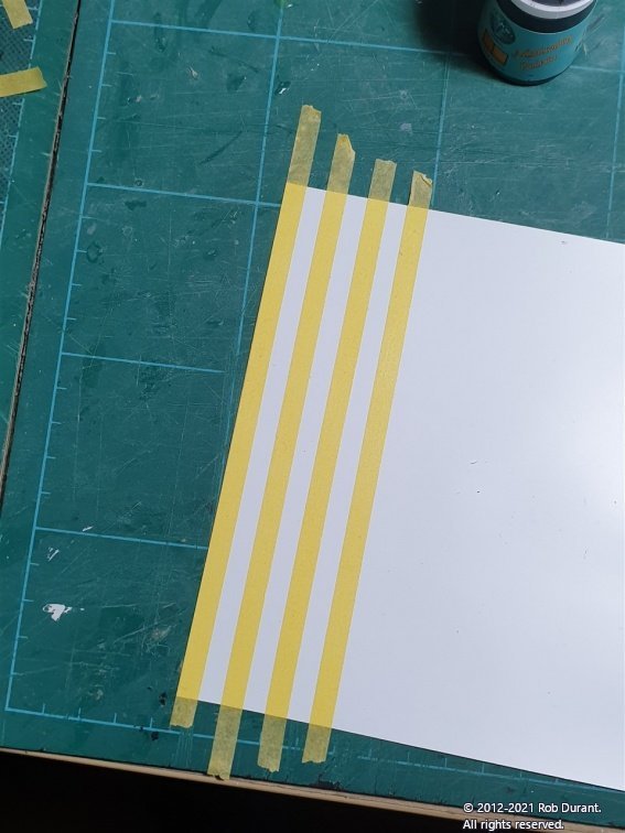
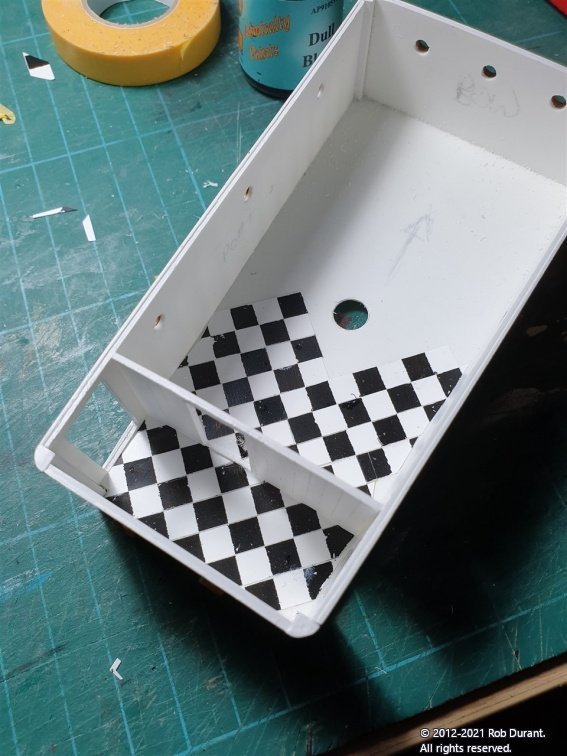
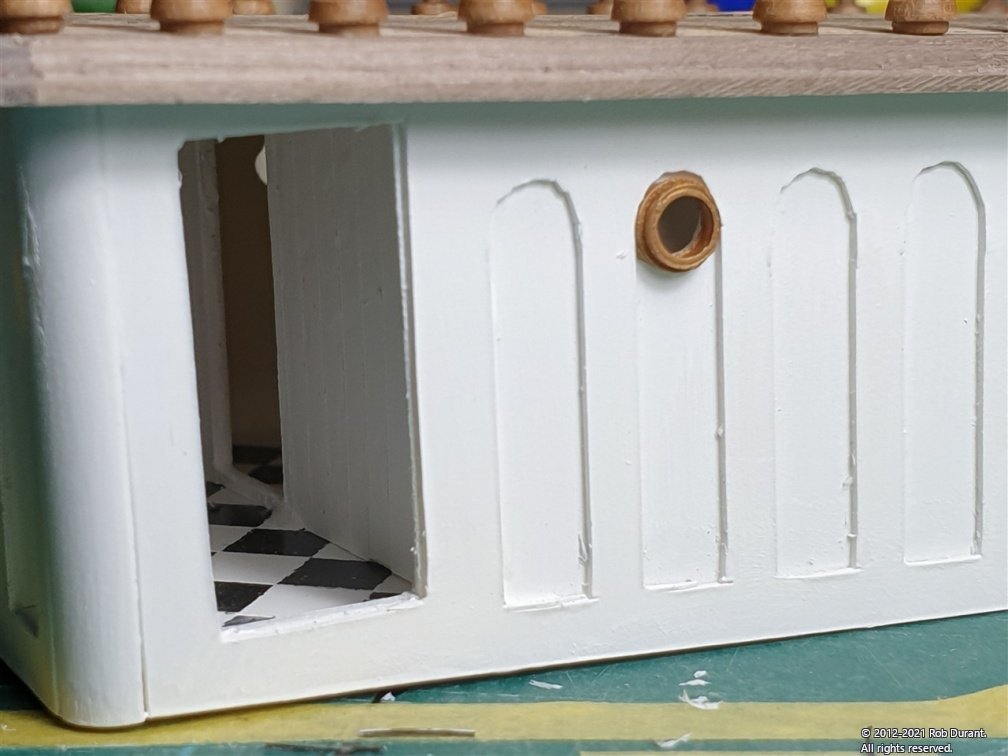
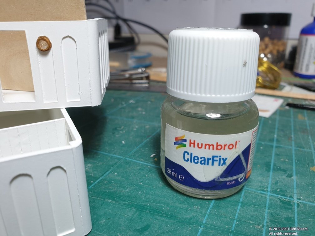
I've placed the columns on the other side of the aft cabin deck. Once the glue was well set the whole unit was turned upside down and very gently rubbed over sand paper to add the slope to the top of the columns ready for the railings. The railings were made of 15cm lengths of 1x4mm walnut, with a 0.5x2mm walnut strip glued down the centreline stopping a millimetre from each end. I've also started detailing the insides of the aft cabin with a tiled floor made from 0.13mm styrene. The styrene had 6mm masking tape placed in stripes spaced 6mm apart. It was then painted black and cut across into 6mm strips. These strips can then be used to create a checkerboard tiling pattern. The pattern was glued diagonally onto the floor of the cabin, and the partition wall glued in place over them, such that when looking through the doors, the floor continues into the main space of the cabin. And the finished result, looks like this. Only a hint of detail, but I think it's quite a nice addition to add interest (and we'll just ignore how brutal the close-ups are!). Since this photo I've glazed the portholes with Humbrol ClearFix as I did with the other cabin. The finished result so far... More soon
-
She's looking stunning. Really lovely work, and good to hear that your energy levels are recovering!
- 60 replies
-
- 2
-
-
- enterprize
- caf
- (and 1 more)
-
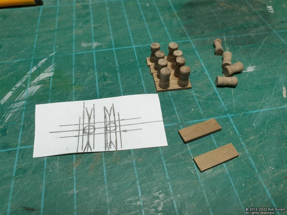
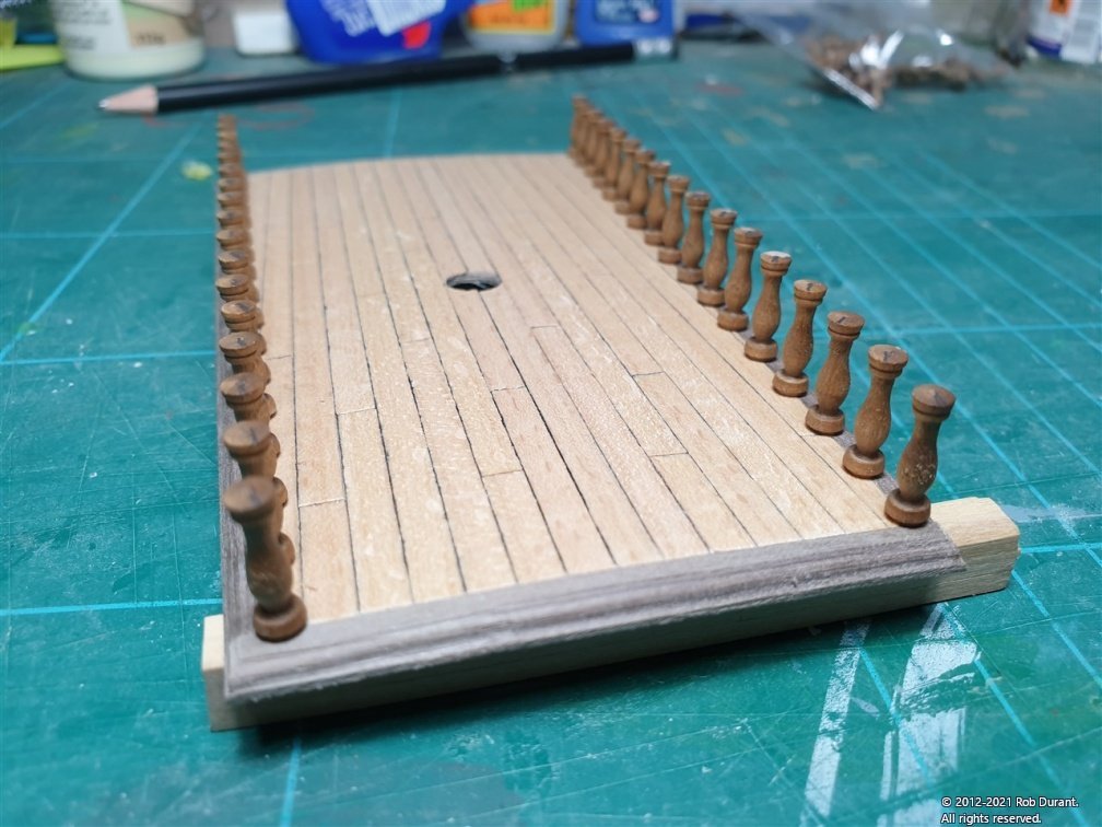
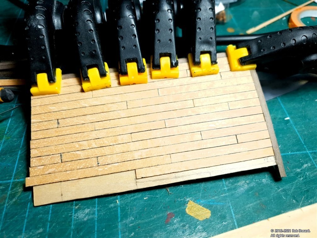
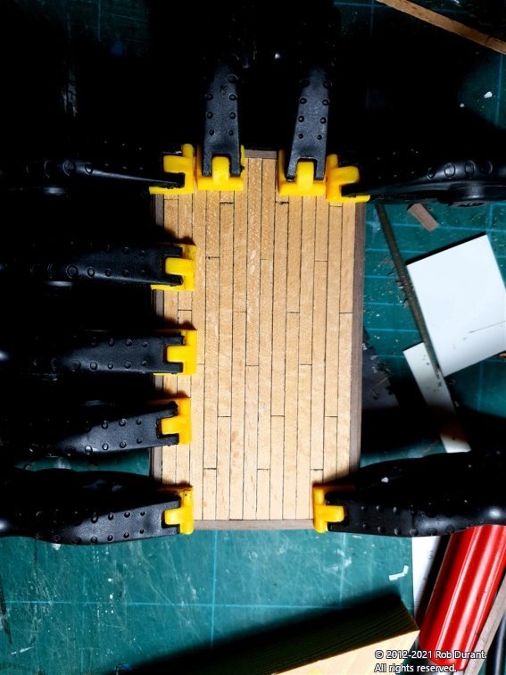
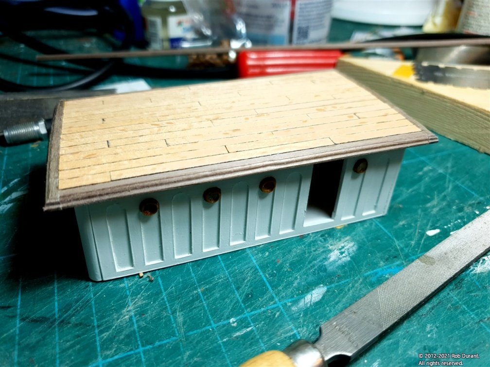
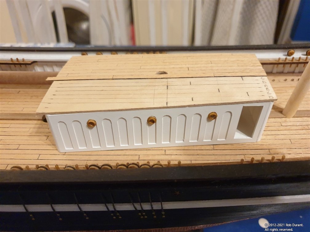
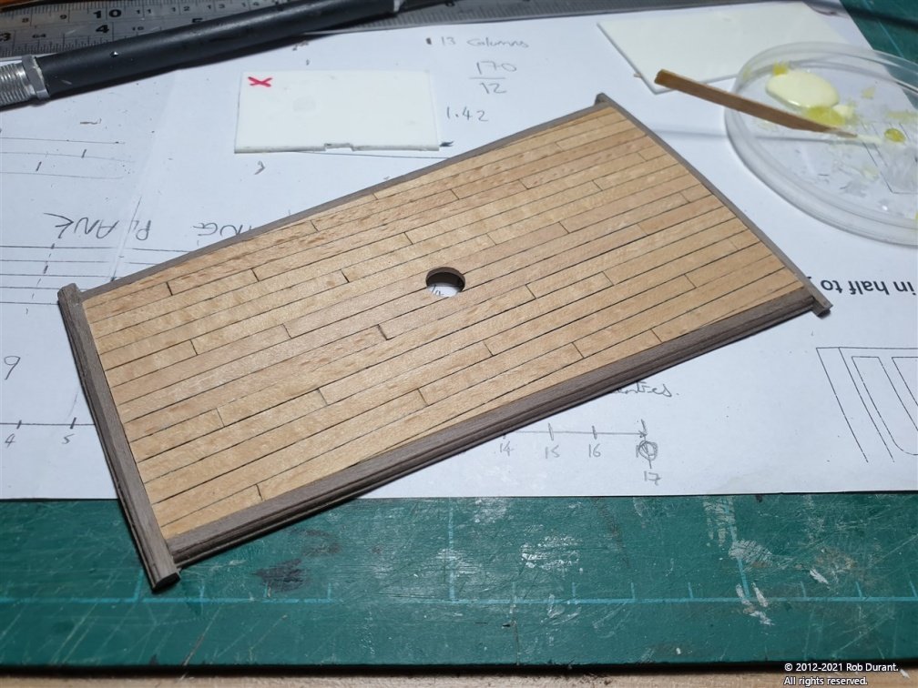
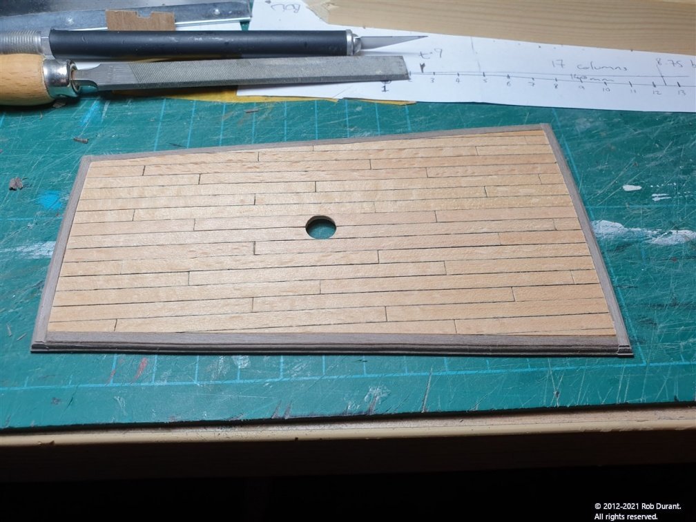
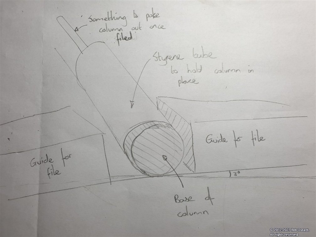
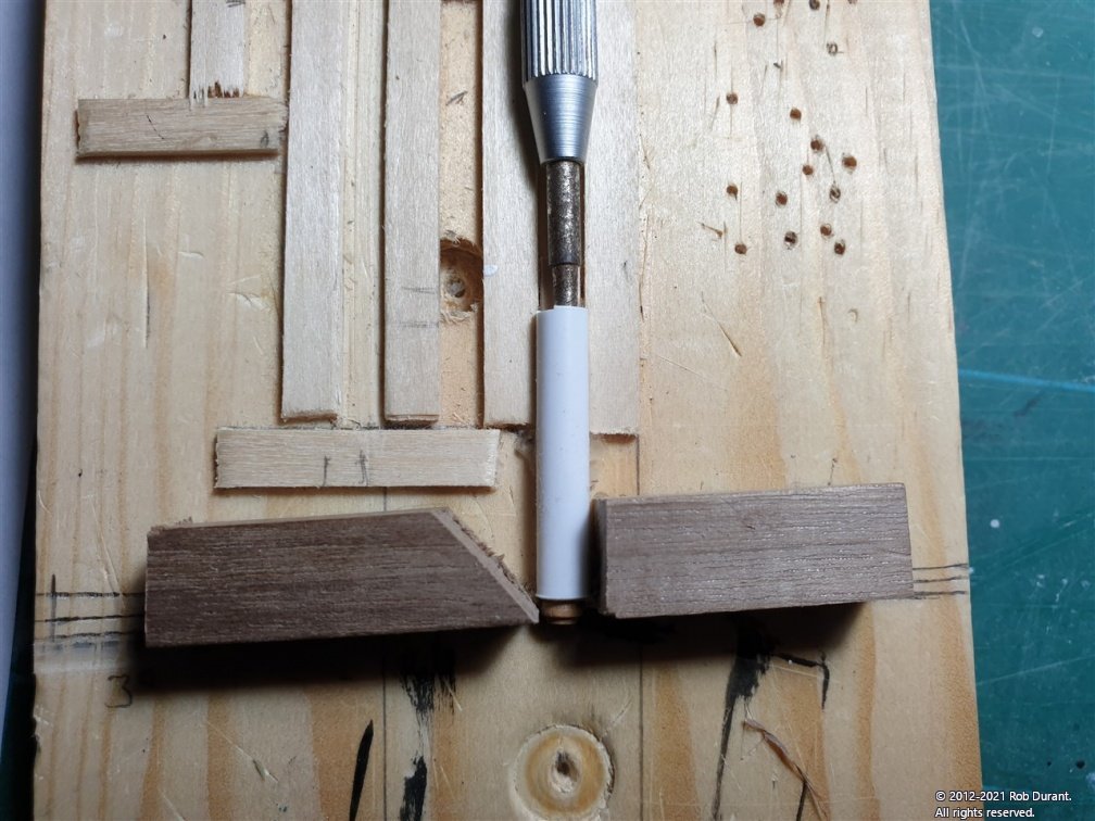
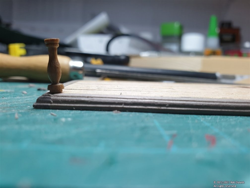
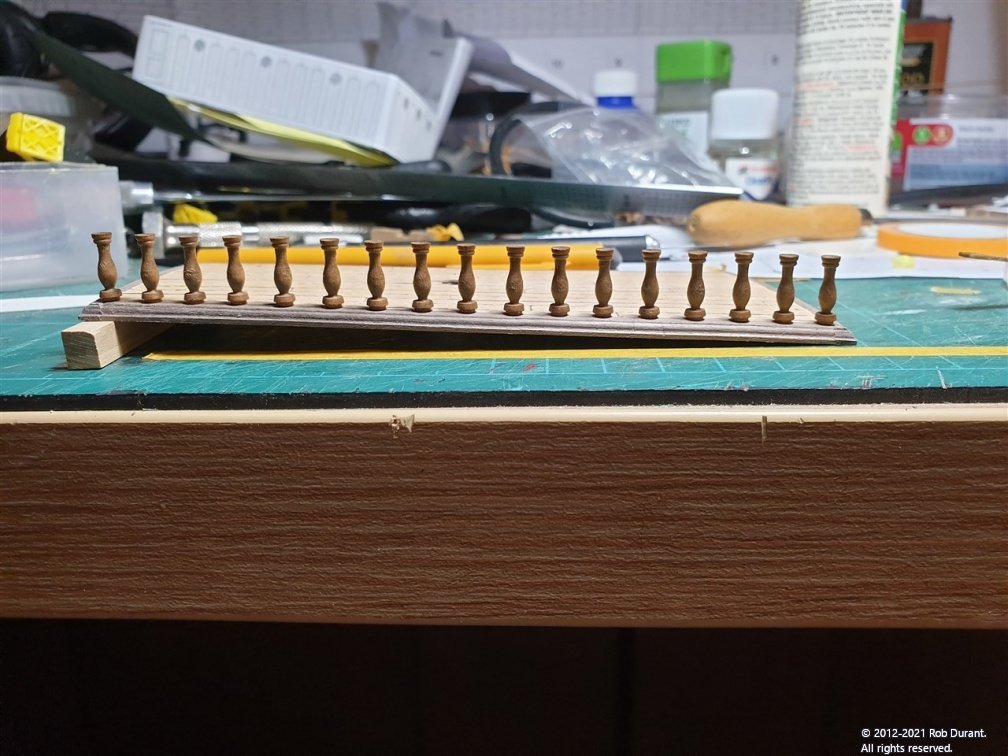
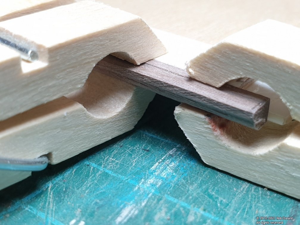
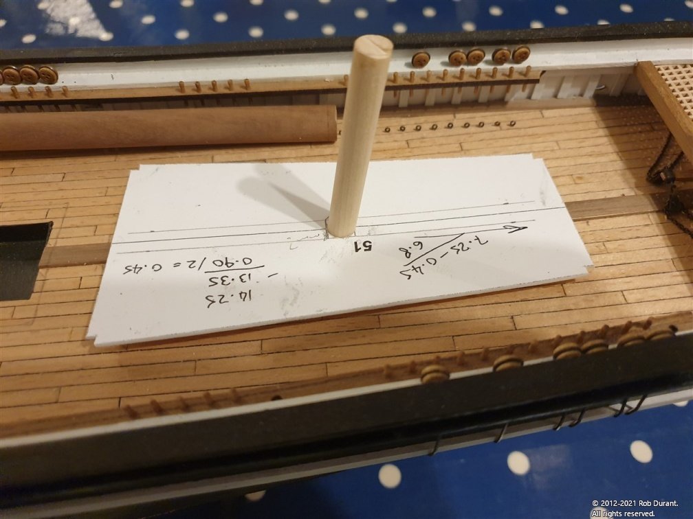
Thanks to you all for looking in, liking, and encouraging me along on this build. I'm finding it fascinating and fulfilling, and it's nice to know that others are finding enjoyment in it, too! I took another look at the cabin roof, and compared it with those on the Cutty Sark, and realised that the profile was the opposite way up (thick at the top and narrow at the bottom). Not a big deal, but it niggled at me, and I decided to try it the other way round. Through my own laziness in not taking progress shots, I also neglected to take photos of me sticking planks onto the cabin roof only to realise that I hadn't cut them to scale length... so - here are some shots of the work, which I obviously got right first try!!! 🙄🤣 One of the benefits of re-doing it, is that I realised it made sense to plank from one end, over the other end, and then sand it back to get a neat transition to the surround. Then the surround was glued in place... And the profile was carefully filed back into the corners where the joins were (yes, I wimped out of trying to do neat 45 degree mitres!) Then it was a case of rinse and repeat for the aft deckhouse, with the added challenge of making sure the hole for the raked mizzen mast was in the right position. (Achieved by measuring back from the front of the deckhouse when the deck was not in place, and then transferring this measurement (plus the overhang) onto the deck. The next thing I wanted to have a crack at was the railings. They could probably wait a bit, but I was itching to see what they looked like! There are 17 each side, covering 140mm between the centres of the columns at each end (at least on this interpretation!), and that leads to an 8.75mm gap between column centres along the row. The aft deck has a 3 degree slope, rising from front to back. It also has the camber to allow water to run off. I made a jig to allow me to file the bottoms of the columns evenly to 3 degree angles. By turning the column slightly so that the angle faced inboard, I could account for the slope fore and aft, and the camber. I've drawn a very rough diagram here... And the actual jig looks like this... You can just see the column poking out from the end of the styrene tube. When the column was removed from the styrene tube, I marked the top to show which direction the angle was (it's barely visible to the naked eye!) Then these marks were used to line them up as I glued them in place. I've only done the starboard side so far. When the deck is laid flat you can see the angle (I made up a small 87 degree angle piece to check against.) And a few pictures of the side, finished. The wide angle lens makes the end columns look like they're at different angles, but they are in fact all as near parallel as I can get them. I'll gently sand the top to add the angle to the columns for the rail, and once added, the whole structure should be reasonably strong. Right. I think that's enough for this evening. Happy building to you all Rob
-
Thanks Vladimir I've been planking the cabin roofs so I hopefully should have another update by the end of the day.
-
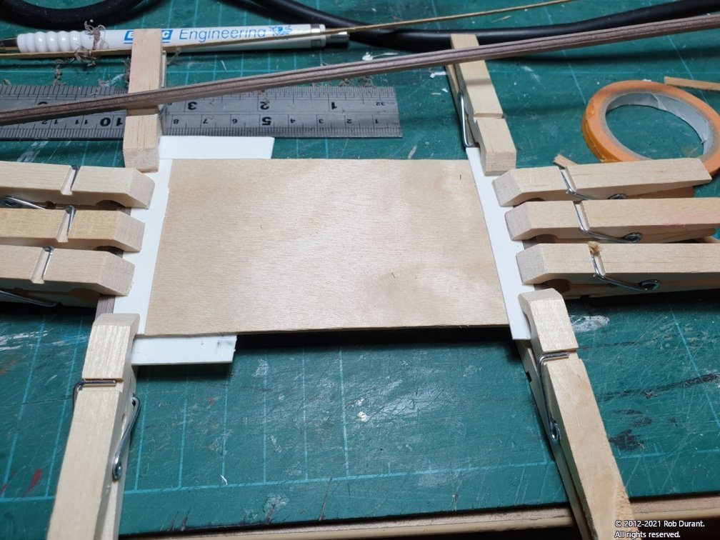
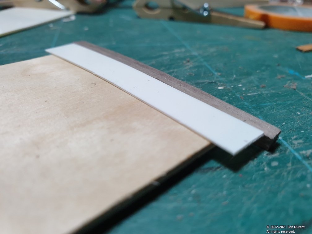
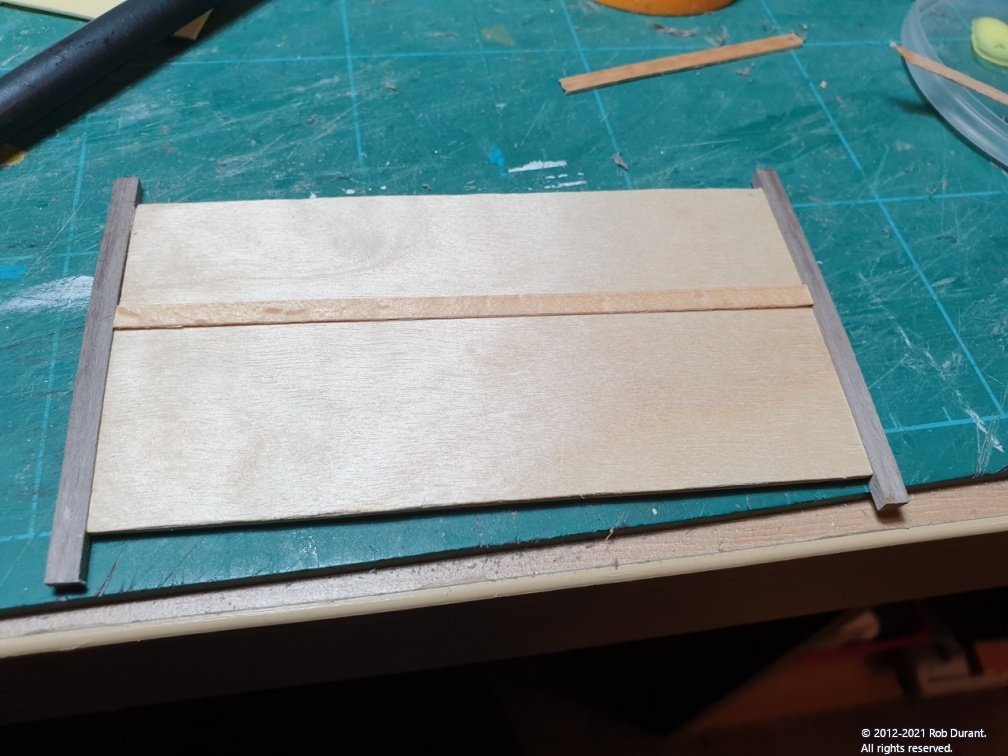
I tried glazing some of the portholes, which seemed to go very well. More practice would not go astray, but that's the beauty of Humbrol clearfix, you can just go back and have another crack at it. I have yet to put the portholes into the aft superstructure. I used my violin rib bender at 230 C and water to warm the ply roof formers and introduce the curve of the deck (it never seems like a good idea to me to simply try and make the glue force wood into a curve). Then I took some walnut 4x3 strip and using Artesania Latine micro shapers (https://artesanialatina.net/en/micro-tools/1296-micro-shapers-b-wooden-plastic-models-miniatures-tool-8421426273014.html - the bottom right shape of the middle scraper in the picture on this site. The profile was put into the entire 1mm length of the strip, and a length of it bent vertically to match the contour of the cabin roof. It was glued to the cabin roof clamped with a 0.5mm strip on the plywood so that there was a lip of 0.5mm. THis means the decking should sit flush with the surround, eventually. That's the plan, anyway. In this photo you can see the profiled strip at the back, and I'm gluing each end to the cabin deck ply. Once the pegs are removed it looks like this... And because I used plasticard for the spacer, it doesn't stick to the carpenter's glue I used for the wooden strip. It simply lifts away, leaving the lip for the decking to be applied. And here's a decking strip which seems to fit nice and flush. (I do love it when a plan comes together ) The next task is to cut nice neat mitres at each end of these pieces so that I can add the lengthwise edges. Before I do that I'll plank the deck, so I can get the edges really nice and neat. That way, when I glue the edges on, they'll simply butt up against the decking, and I won't have to worry about the 0.5mm lip. More soon
-
What a great idea! You've reminded me, I have some already tucked away in the back of my paint cupboard I shall fish it out and see if it's still serviceable. I've used it in the past on a 1:96 destroyer, and it was brilliant. I've just got out of the habit, because my more recent models have had gunports or stern lights! It's useful for sticking in clear plastic without clouding it, too.
-
Thank you Rob. Yes, I shall glaze them from behind. I'll probably used clear plastic, as I have some left over from a previous build. I was thinking that a hole punch might be a neat and efficient way of making the circles.
-
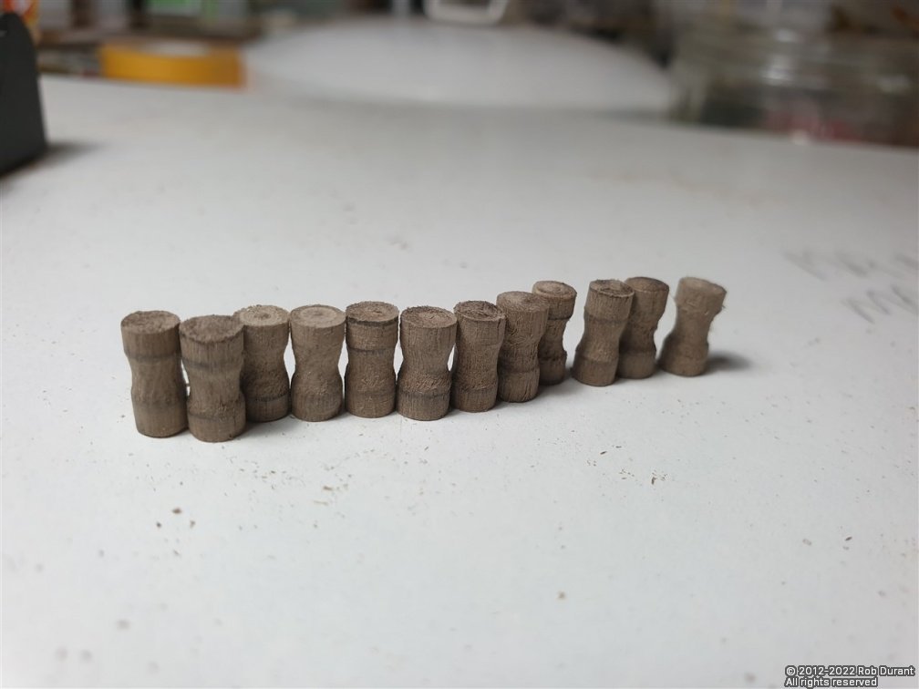
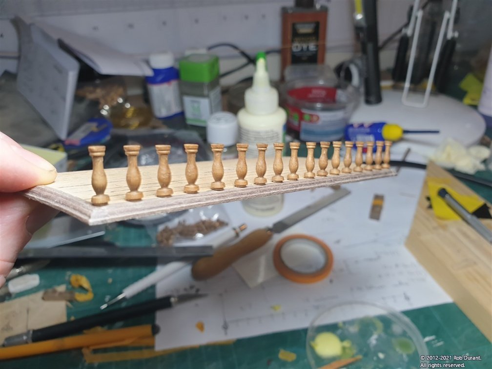
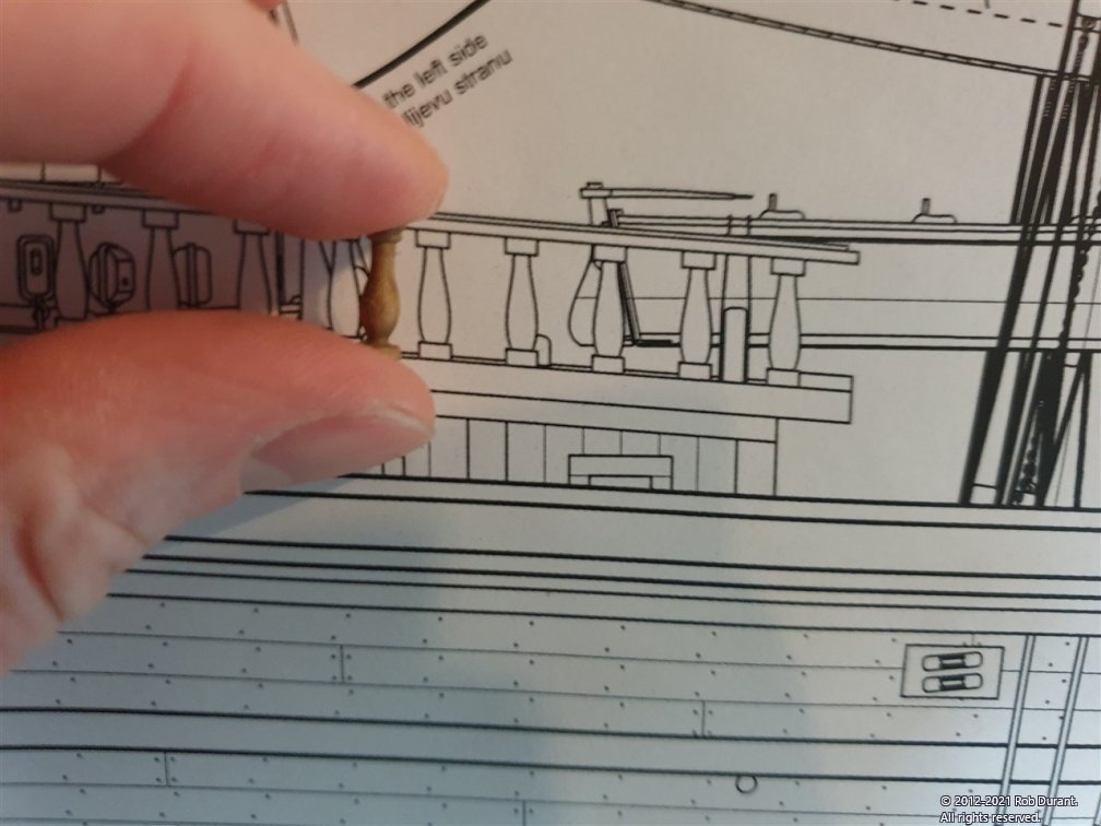
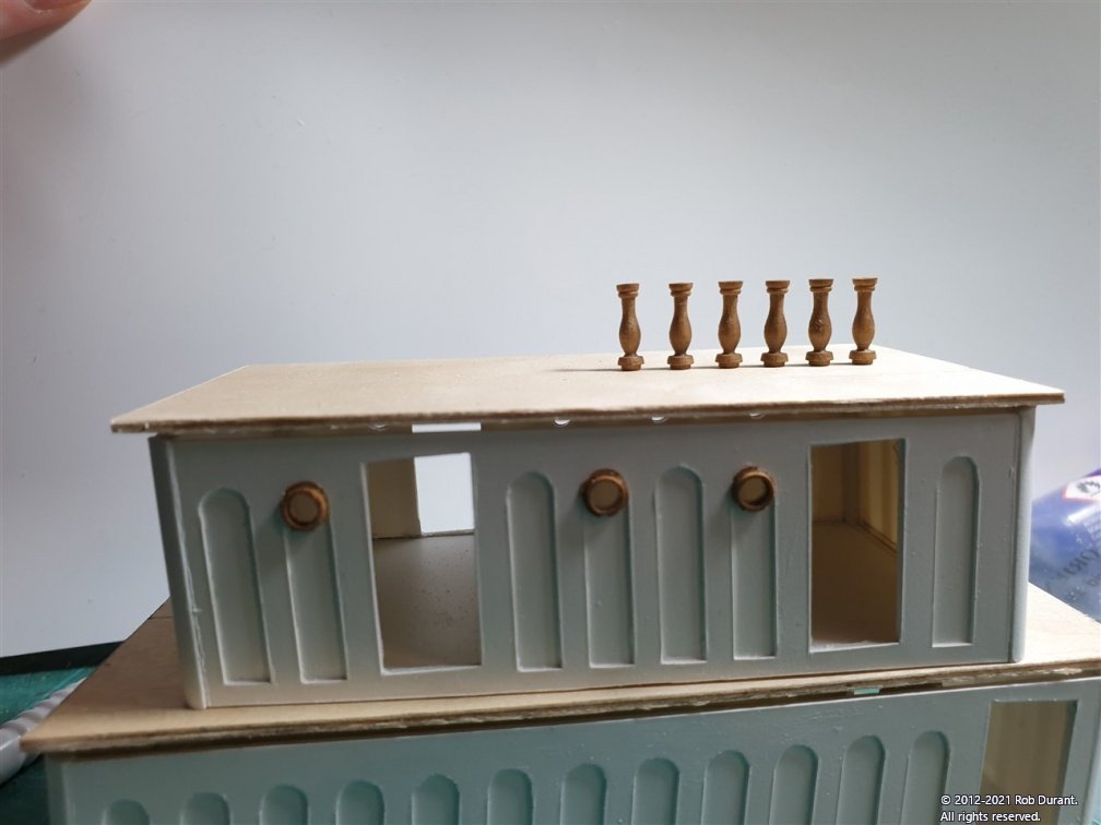
Thank you Rob. Again, a little progress this evening. I have drilled and filed out the porthole openings in the forward superstructure and fitted the portholes. The deck is as yet unbent, but I'll bend it with water to give it a water run-off. I've also found some columns for the railings that are close to those on the plans. These are Amati walnut 12mm columns (I bought 70 of them, which should be enough, with a few left over!). And a few lined up for effect... They're a tiny bit over height so that I can file the angles into the bases and tops to make them vertical on the model (even though the deck is sloped a few degrees.) Happy building all Rob
-
Thank you Rob, your work on Glory of the Seas has been a great inspiration to me, and having followed your log, I gained the insight to acquire a copy of Underhill's Masting and Rigging the Clipper Ship and Ocean Carrier which looks like it will be a great resource once I get to that stage, as there is no belaying point plan in the kit for Stefano (that I've found, anyway). It's a wonderful task you're engaged in recording and replicating these amazing vessels! I had the privilege of living less than ten miles from Cutty Sark in Greenwich, London for a number of years, so was able to visit her and give thanks that she was not more damaged by the fire she suffered. The Clippers (from both sides of the Atlantic) are undoubtedly some of the most handsome ships ever built. To my eye, the Barque Stefano also catches something of this beauty, though she's a smaller vessel. Each material has its strengths and weaknesses, and those lend it to different tasks. The ability to cut such thin plastic so simply without having to watch out for grain direction or splitting was a great draw for this purpose. To use wood would have required veneer, which I find hard to work, and as it was going to be painted anyway, it was a done deal. It is lovely having those natural wood tones alongside, too
-
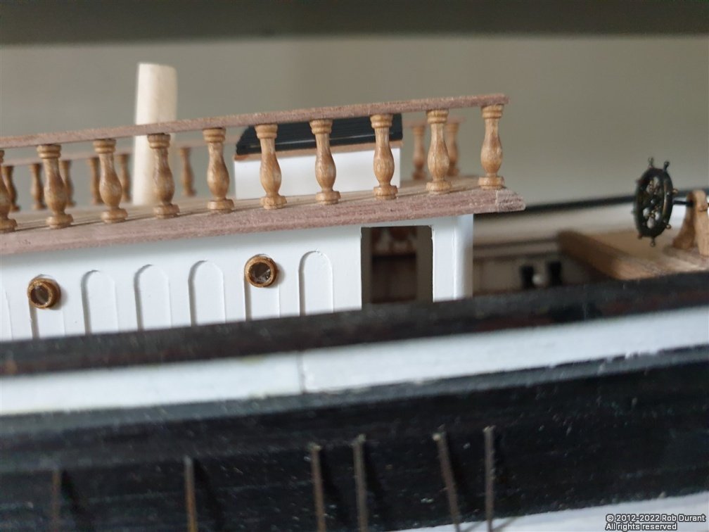
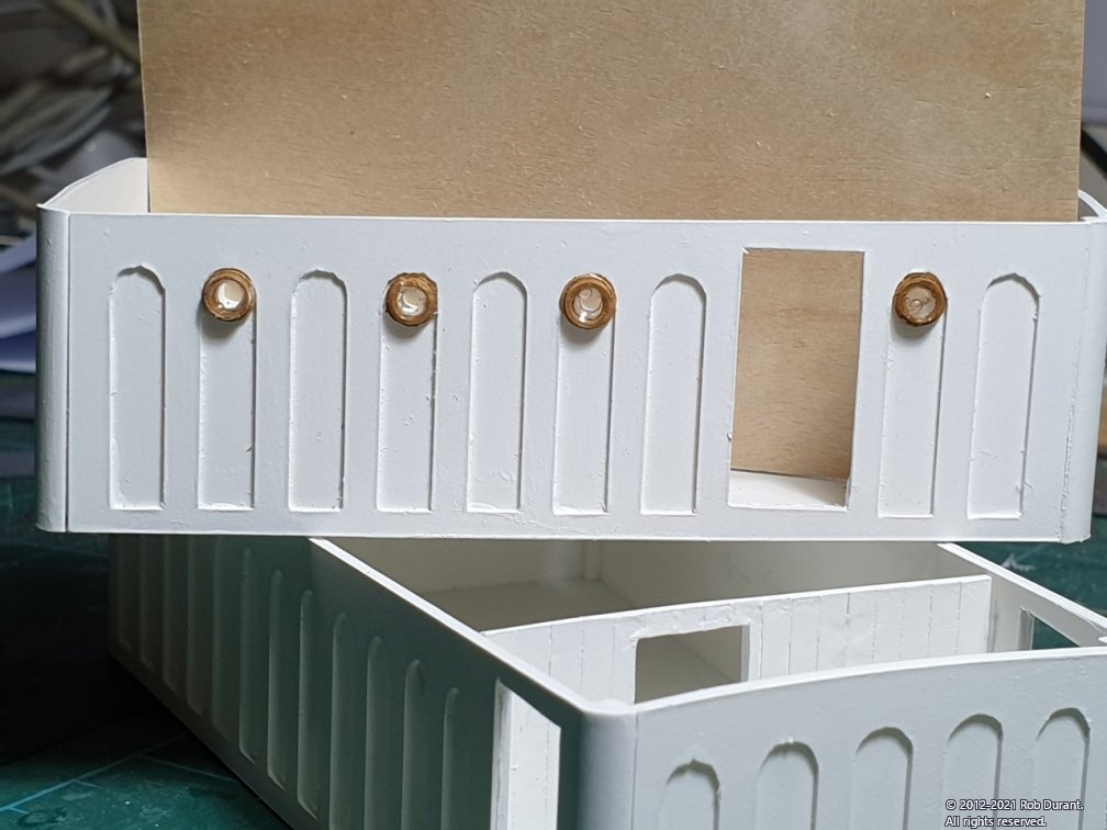
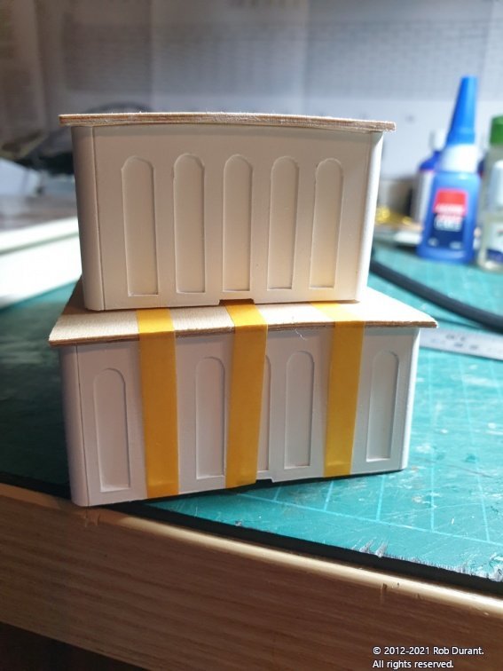
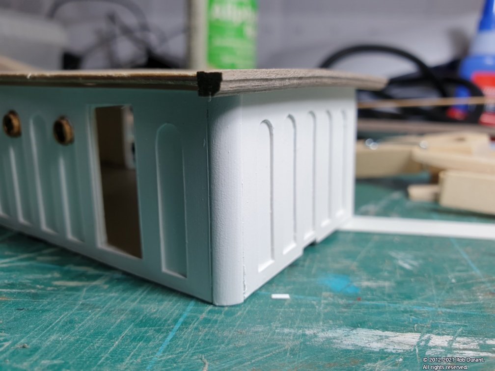
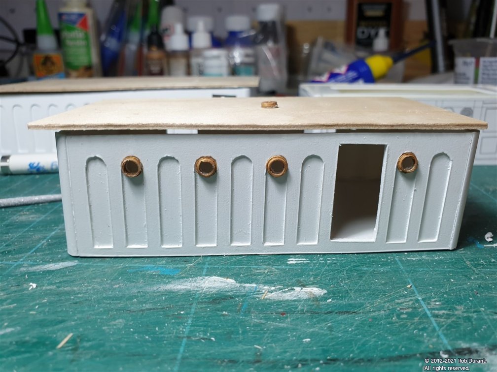
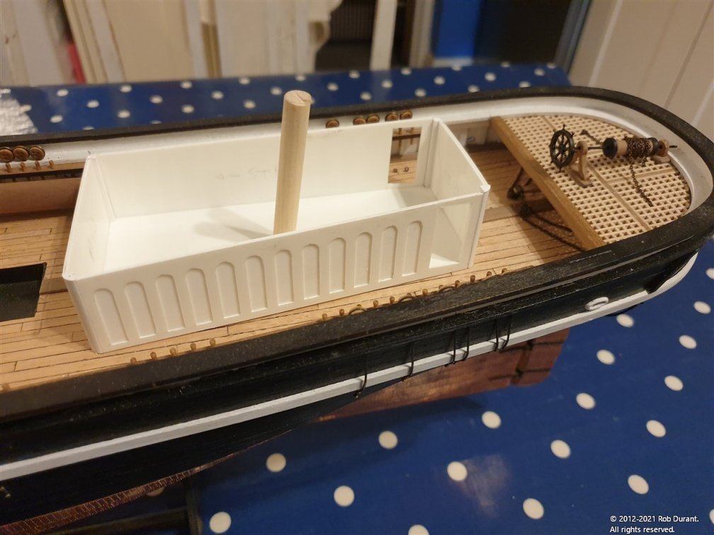
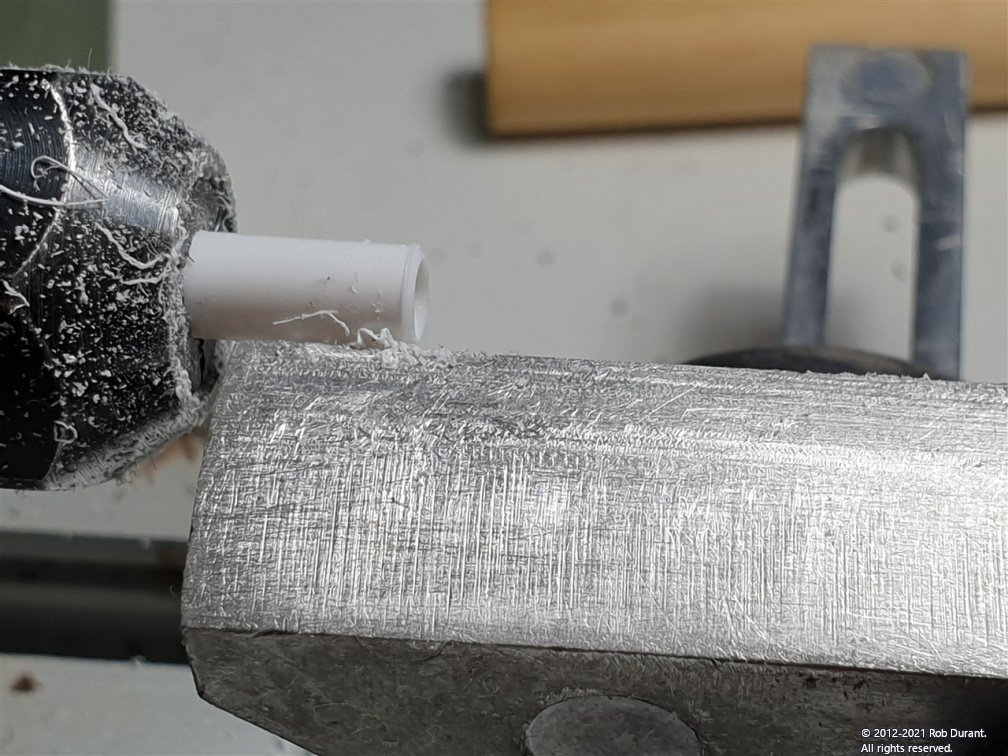
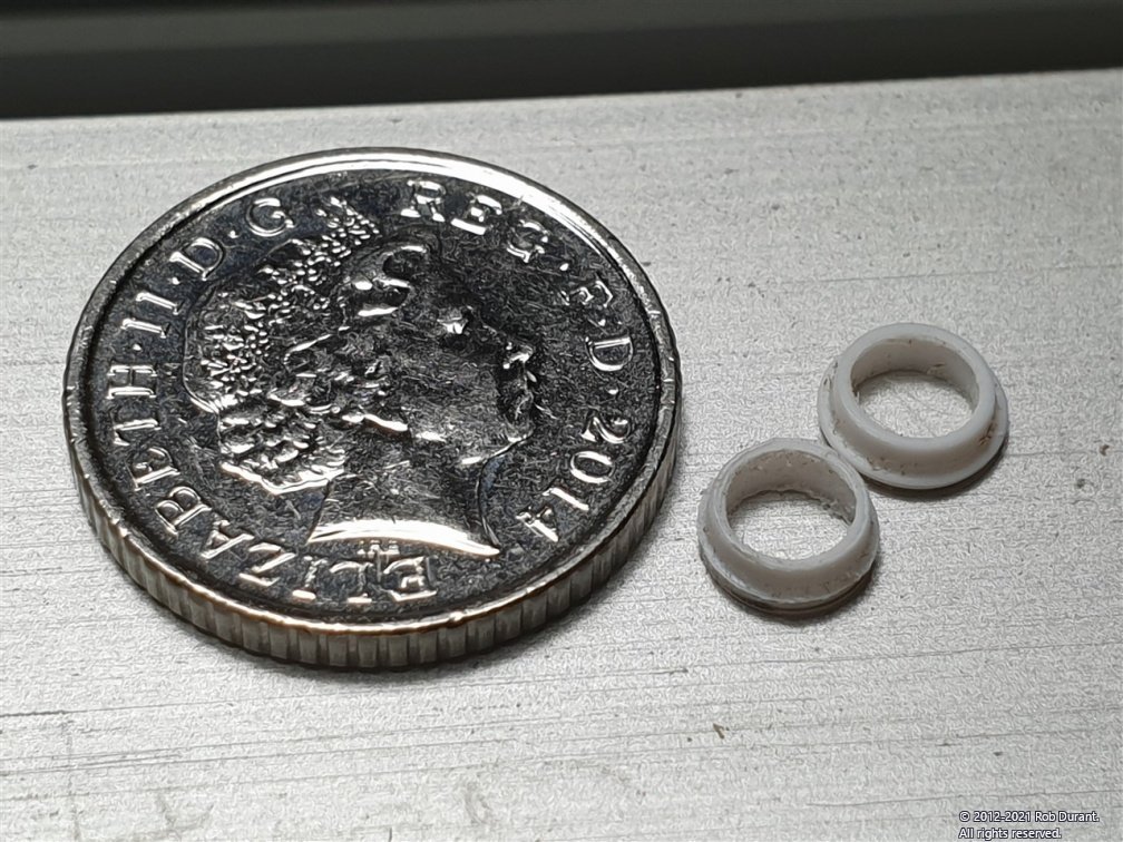
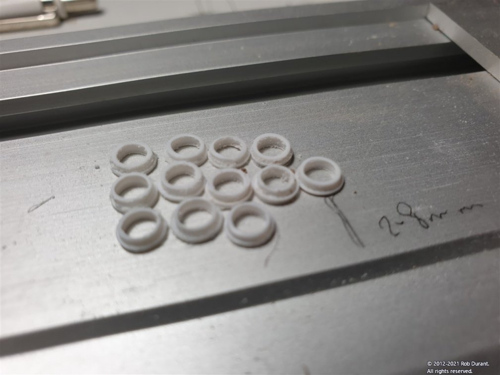
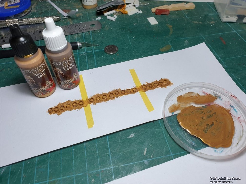
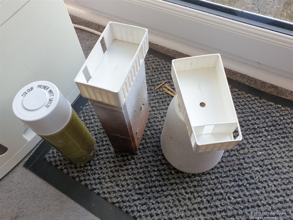
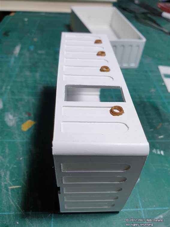
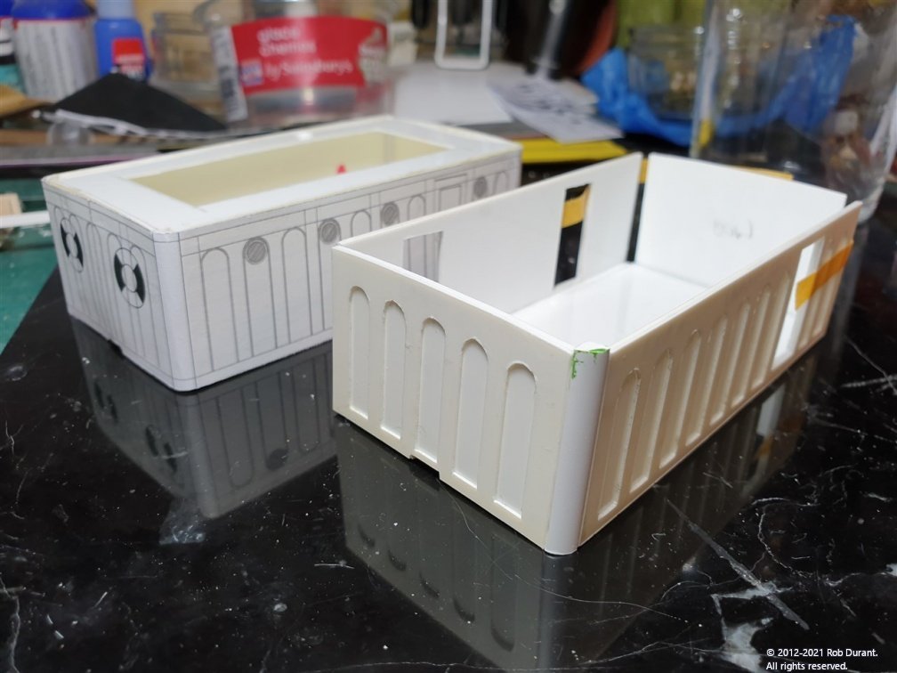
Morning all, Thank you as always for your encouragement, comments and likes. I've continued working on the superstructures. The aft superstructure was made in the same way as the fore s/s. When fixing the layers to one another, I've found a floor tile (purchased for photo-etch work) very useful as a flat reference to make sure I don't laminate a curve into the parts. Because this superstructure is not rectangular, but trapezoid, the floor had to be carefully measured to account for the thickness of the walls, and the 3.5mm quarter round section which would be used at the corners. Even with careful calculation a little fettling was required to allow it to fit together nicely in real life. The final challenge was to make sure that the hole for the mizzen mast was in the correct position. Once assembled, I was happy with the results. Happy with that, it was time to think about portholes. I wanted portholes with a very minor flange, and very thin wall. I couldn't find anything commercially available, so I decided to make them myself from 5.8mm styrene tube on my proxxon lathe. My design calls for 18 of these, and they were all made in the space of a morning. Care has to be taken not to overwork the styrene and melt it. Then it was time to paint them with some bronze paint (gold mixed with a little brown) A partition wall was made for the aft superstructure from 1mm "planked" with 0.13mm styrene. Finally, I sprayed the superstructures with white primer, and then hand painted with a few coats of Caldercraft matt white (with a few drops of water to make it flow better and avoid brush marks). I haven't drilled out the holes or fixed the portholes in place yet, but this photo gives you some idea of what it might look like. Looking at this photo, I think I need to sand them a bit thinner, still. But that's it for today Happy building. Rob
-
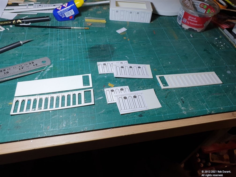
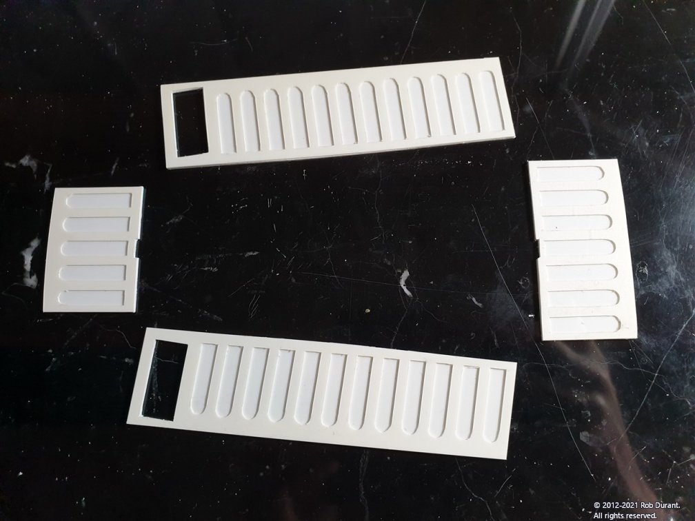
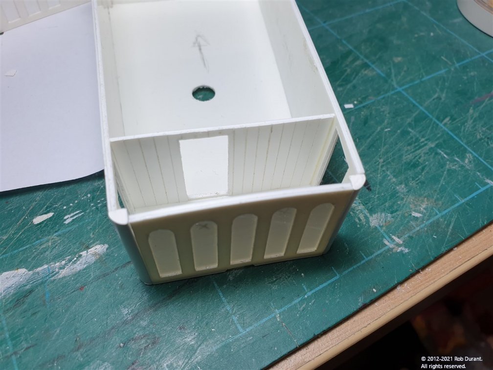
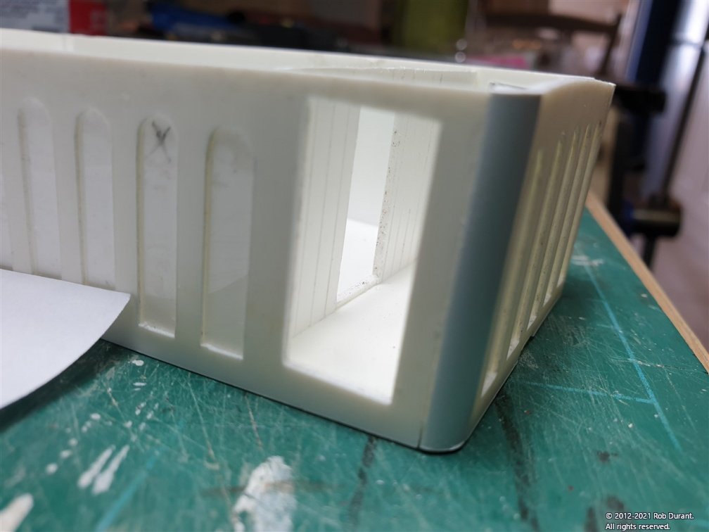
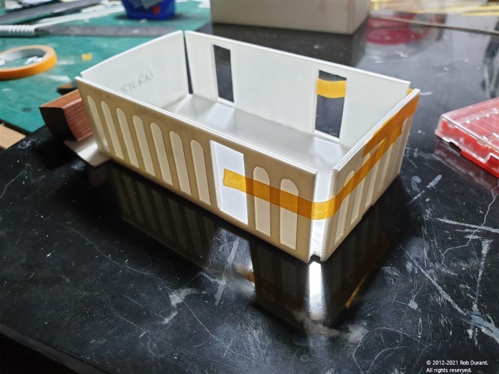
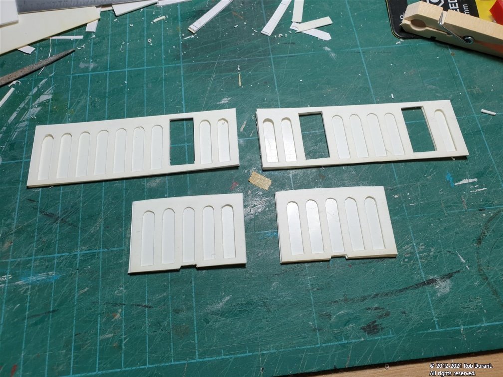
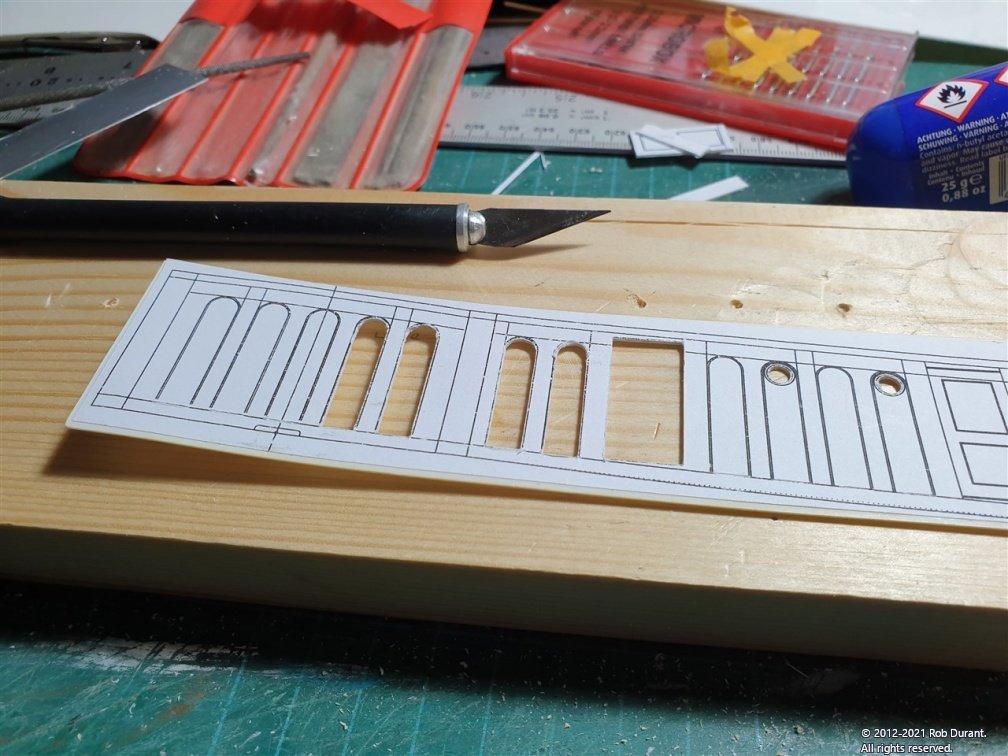
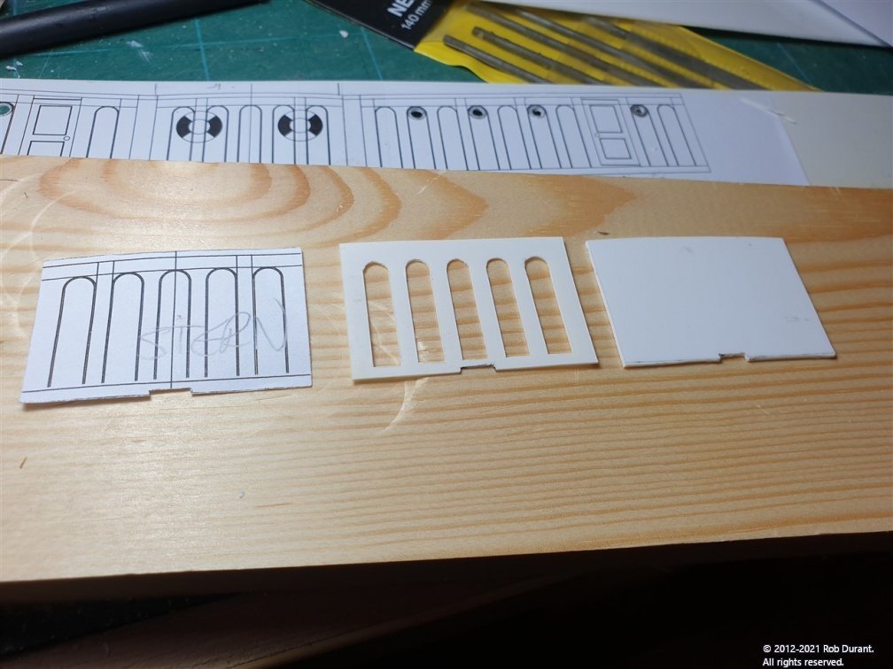
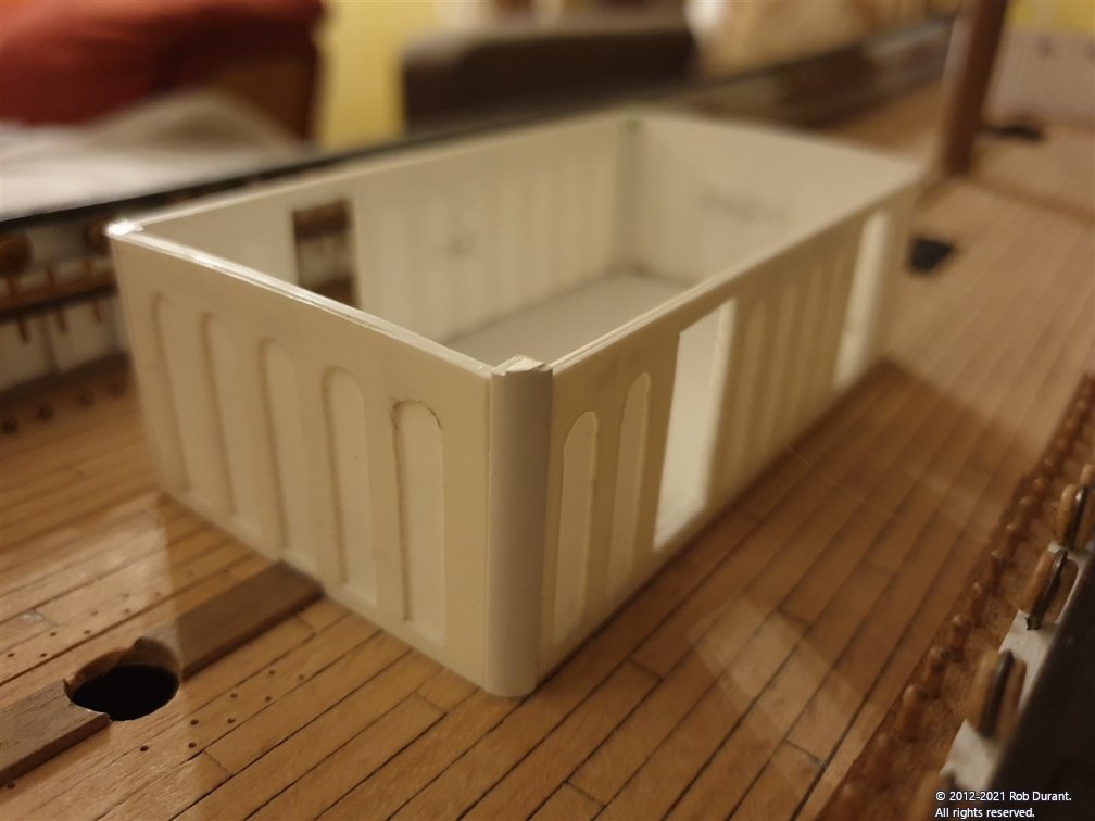
Well, I finally got sick of staring at the card mockups for the superstructures, and decided to have a crack at making them in styrene (or HIPS - High-Impact PolyStyrene) to be precise. I bought a shed load of this when I semi-scratch built my HMS Cottesmore, and it's been sitting tucked down the back of my boat desk since then. I printed the CAD designs I'd put together - the original idea was to photo-etch it - and pritt-sticked the design onto the plastic. The shape was then cut out in two levels. The arches in 0.5mm plastic, and the main sides of the superstructure in 1mm. I tried to make the corners with styrene tube cut into quarters (as difficult to do as it sounds!), and quickly decided it wasn't going to be accurate enough. So I then purchased 3.5mm quarter round evergreen styrene to fit into the corners. A base was designed that would help give the structure strength, make sure it was square, and act as the floor inside the cabin. I've been through a few x-acto blades, and I'm never going to rival the masters on this forum, such as @Hubac's Historian, but I'm pretty happy with the results so far. I'm hoping to put a black and white floor in and part-opened doors, along with scale portholes, which I may well need to photo-etch, as the ones I've seen to purchase look to me over scale. Here is the progress so far... Cutting out the parts... And assembling them - this took two attempts as the first attempt ended up warped. I took it apart and assembled it more carefully, ensuring that the base plate was glued evenly. NOTE: The base plate needs to be raised off the deck a little for two reasons. One the deck curves from fore to aft, and two, because there is the king plank on the deck that passes through the cabin underneath the floor. And a shot of the Barque as she stands - apologies for the quality of this shot, but the lighting was awful. I'll try and get some better ones soon. Aft cabin next, but that's one for another day. Happy building Rob
- 286 replies
-
- 15
-
-
Stunning work, and definitely the right call to remake those trim sections above and below the upper counter. As always your work is an inspiration.
- 857 replies
-
- 4
-
-

-
- Sphinx
- Vanguard Models
- (and 1 more)
-
Very neat work with the lights. I just found this thread. Hope you don't mind if I follow along. It looks like you're making great progress! 1:50 is a nice scale to work in. How big will she be when she's rigged?
