


robdurant
-
Posts
843 -
Joined
-
Last visited
Content Type
Profiles
Forums
Gallery
Events
Everything posted by robdurant
-
 Thank you all for the likes and encouragement It's very very good to be back in action again. Looking at the plans, I realised I hadn't shaped the front edge of the rudder - nearest the hull - before plating it. With some careful application of a sharp scalpel blade, I was able to carve this wood away, and then wrap the copper round, as it now protruded a couple of millimetres in front of the front edge of side of the rudder. Then I got stuck into making the pintles and gudgeons. But real life calls, and I think that subject deserves a slightly more in-depth post, so I'll write about that tomorrow. Happy building, all! Rob
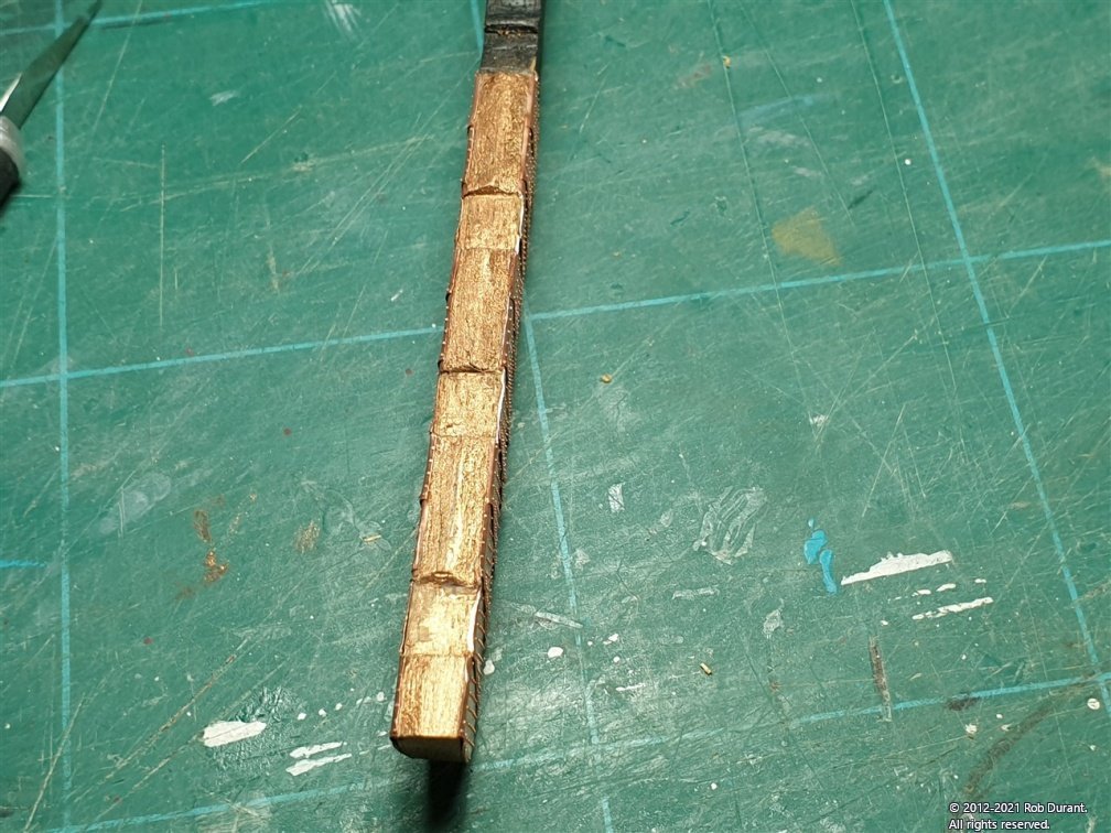
-
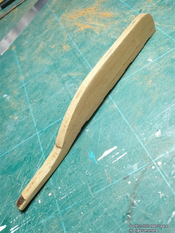
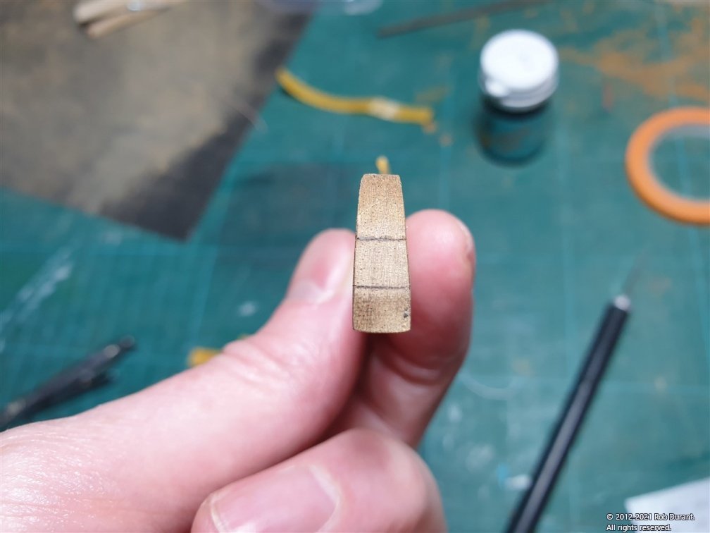
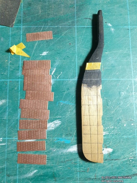
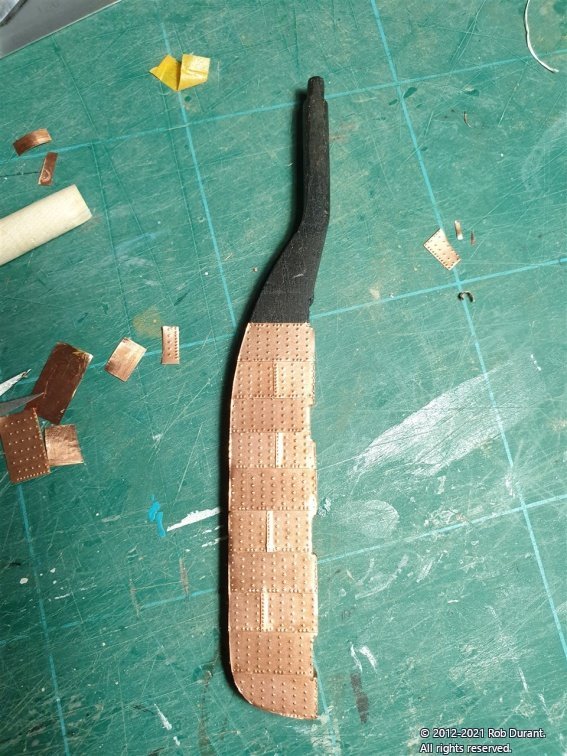
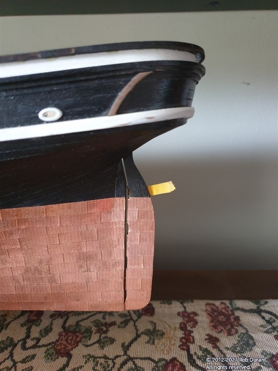
Thank you David, Bob for your kind words, and to everyone for your patience as this build paused. I'm pretty much back to normal now, and work has eased just a little, allowing me time to get re-focussed on Stefano, and back into the shipyard. I have a little progress to report. I was conscious that I'd coppered the hull, and it was gradually beginning to gain a patina, but I had not coppered the rudder, and I didn't want to end up with a rudder that looked like it had been put on the ship at another time. So, that was the next job. This was surprisingly tricky to think through, as the tiles overlap from the bottom up, and they need to finish at the perfect point at the top. Equally, I didn't want to have a part tile if I could avoid it. So a bit of measuring, and head-scratching, and lots of pencil-marks later, it CAN be done... Before I started, however, I removed the laser char from the rudder, and made it wedge shaped, so it narrows from front to back. I think this little touch makes the rear end of the vessel look much more delicate, and I can imagine this would help the hydrodynamic properties of the hull, too, perhaps? (nb: The tiles are sided - (and in this picture upside-down!) The tiles have vertical rivets at the rear, and the top tile has rivets along the top AND bottom...) Finally, some copper paint was added on the front and back faces of the rudder, and then it was trial fitted in place... Right - now I need to go and read the manual and work out what I'm supposed to be doing next Happy building, all!
- 286 replies
-
- 10
-

-
Hi Steve, I've built both Pickle and Sherborne, and was so glad that I started with Pickle (my first wooden ship build), and THEN went onto Sherborne. The instructions on Pickle are way way way better, consisting of photos, advice, and comprehensive instructions. The instructions for Sherborne are far more brief, and text only alongside the plans. They were okay, but I felt I had to rely heavily on what I'd learned building Pickle. I haven't built Lady Nelson, so I can't advise on that one, I'm afraid. You can check out the instructions for Pickle on the Jotika website, here: http://www.jotika-ltd.com/Pages/1024768/Manuals_Front.htm , and you'll find lots of build logs on the website here to help you along. However, as Chris pointed out, the kits that Chris Watton is now designing (for his Vanguard Models company) are another step up in terms of the help they give you to ensure you get to the other end with a model you can be proud of. I'm building Lady Isabella at the moment, and the instructions and kit design are quite amazing. Again, you can download the manuals from his website (e.g. scroll down to the "download manual" link on https://vanguardmodels.co.uk/product/order-zulu-lady-isabella/ ) - and you'll see how far these models have come on since you were building Norske Love. Regardless of what decision you make, you'll find a lot of friendly help here on this website, so welcome! Rob
-
Hi Dunnock, Those are looking great! She has teeth now! The walnut(?) carriage parts in my kit of Diana was really flaky, and hard to get a crisp edge with, but you seem to have done an excellent job. The poppy seed is ingenious, too. The monograms for the guns can be bought separately from Chuck's Syren Model Ship Company, here. https://syrenshipmodelcompany.com/laser-cut-ship-model-fittings.php#!/Monograms-English-1750-1820-for-brass-cannon-3-sizes-90-per-pack/p/58972038/category=5764789 I can highly recommend Chuck's carriages, too but you will find that the height of the assembled guns ends up being different (a little taller) than the provided carriages, which can make lining them up in the ports a little more interesting. I guess that's not such an issue on the quarter deck / fore deck. I would recommend working out the heights one by one as you fit them, then fixing the quoins in position, having sighted along the row of barrels to ensure you get a really nice sweep. Definitely one of the show-pieces of these models! Rob
- 310 replies
-
- 1
-
-
- Diana
- Caldercraft
- (and 1 more)
-
She's looking wonderful. You're doing a lovely job of building this kit. The headworks look very sleek and precise.
-
I haven't given up on this build but coronavirus stepped in and I'm still not quite back to the stage where I can get my work done and have energy for Stefano at the end of the day getting better each day though. More soon hopefully. But first I have a holiday for a few days.
-
Hi all, Just spotted this on BBC News... Strong little things those coins, withstanding 21 tons of force on them! https://www.bbc.co.uk/news/uk-england-hampshire-58981472 Rob
-
- 8
-
-
Glad to hear things are looking up for you. You're building a splendid model and it's been a pleasure watching it gradually progress on this build log, so thanks for all your posts.
-
Rob, You my have answered this question before, in which case I apologise, but what is the material that you're using to make the cabin sides? It seems that you are able to score it to mark the panel lines? Certainly, the effect is very convincing.
-
And after a while you can look back and say... "it may be wrong, but it's less wrong than it used to be." A fascinating and very skillful build and build log. Thank you for sharing this learning and growing process with us.
- 756 replies
-
- 3
-
-
- galleon
- golden hind
- (and 2 more)
-
James posted this in the sister thread (Nisha) "All I currently require for this one is the photo-etch and sails" on Sep 8th, so I'd think yes.
- 36 replies
-
- 3
-
-
- vanguard models
- Erycina
- (and 2 more)
-
What an ingenious solution for fixing the mast. She's looking great. Rob
- 273 replies
-
- 4
-
-
- panart
- amerigo vespucci
- (and 1 more)
-
If the original ship ever looked anything near as splendid as your model, what a vessel she must have been! Wonderful work!
- 2,699 replies
-
- 5
-
-
- heller
- soleil royal
- (and 9 more)
-
Thanks Bob, Jobbie. Hopefully have some more progress to show soon.
-
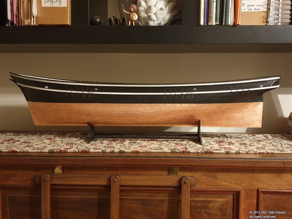
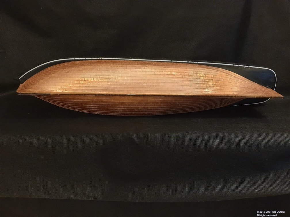
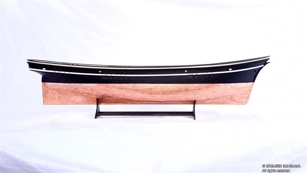
And the port side is now plated as well. Just the line along the keel and up the bow, and the rudder to plate now, but I shall take a breather first. I had to slightly sand the notches in the display stand to make space for the copper tiles which make the keel marginally wider. A couple of pictures, one of which shows the Vanguard Models Zulu "Lady Isabella" for size comparison... Both are almost identical scale (1:64 for the "Lady Isabella", to 1:63 for "Stefano") I have to say, as much as these copper plates are brilliant, I shalln't be sad to have a break from sticking them on individually for a while!
- 286 replies
-
- 14
-
-

-
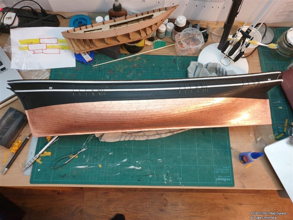
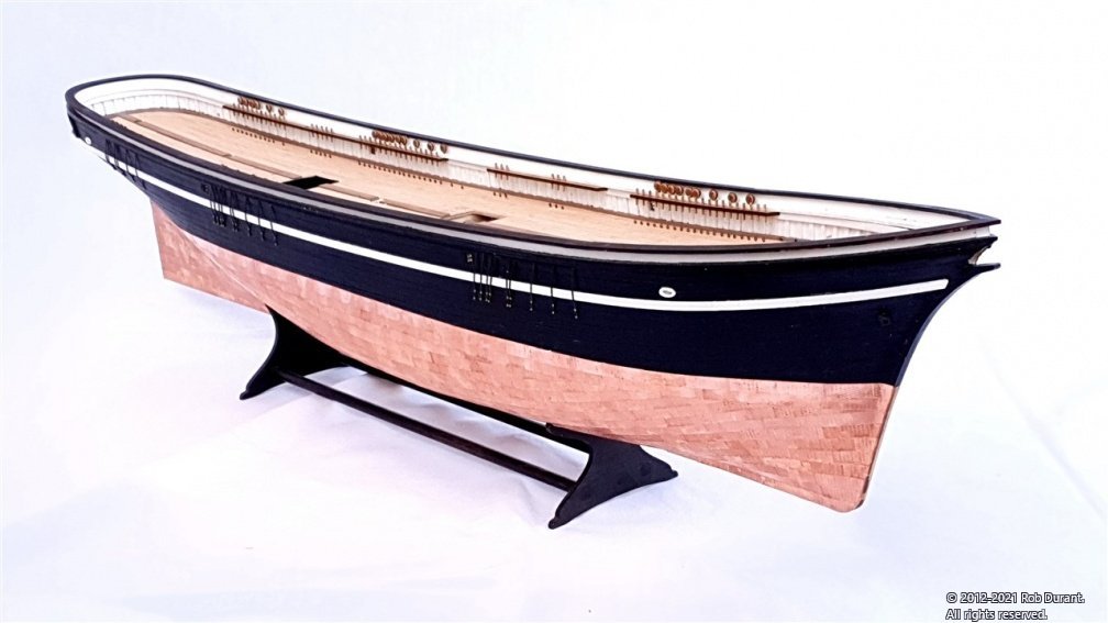
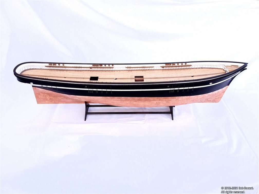
Starboard side plated.... A few more in progress shots, then the finished starboard side. The keen-eyed among you will spot a patch where I did a bit of cleaning of one of the plates... It should blend in again over time.
- 286 replies
-
- 14
-
-
-
Thank you I look back at her now and can't quite believe I built her! A testament to the excellent kit design and great encouragement, ideas and resources on this site!
-
Jason, What beautiful work you're doing on the quarterdeck. Any captain would be proud to wear those planks thin by pacing them on the weather-side! Rob
-
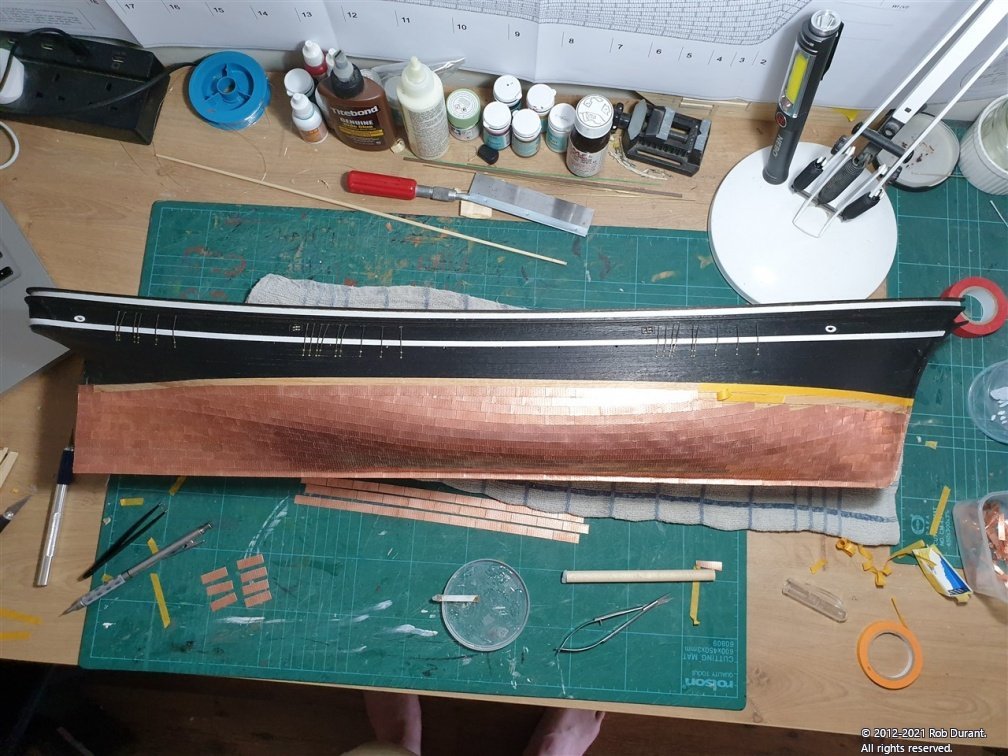
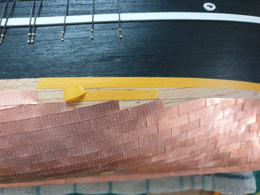
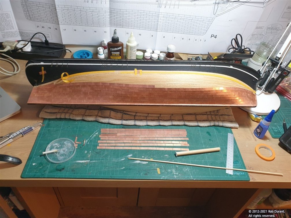
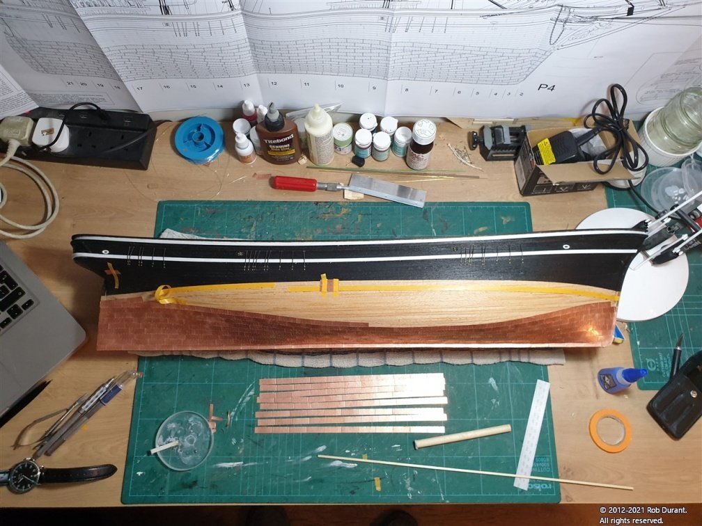
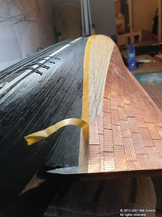
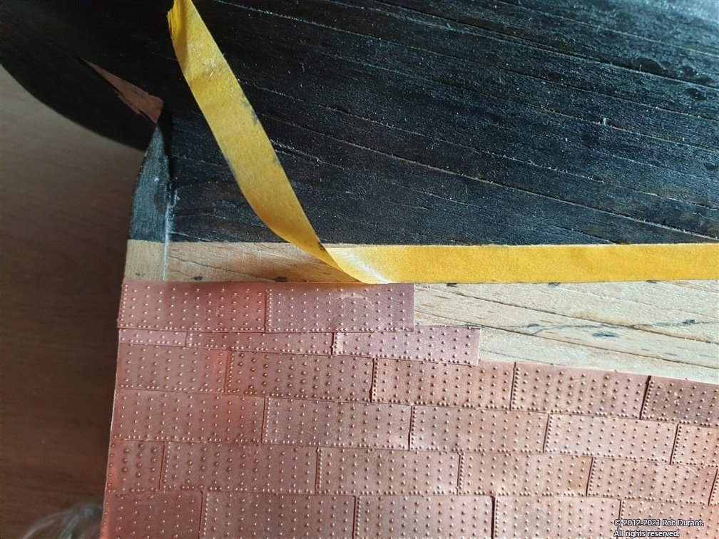
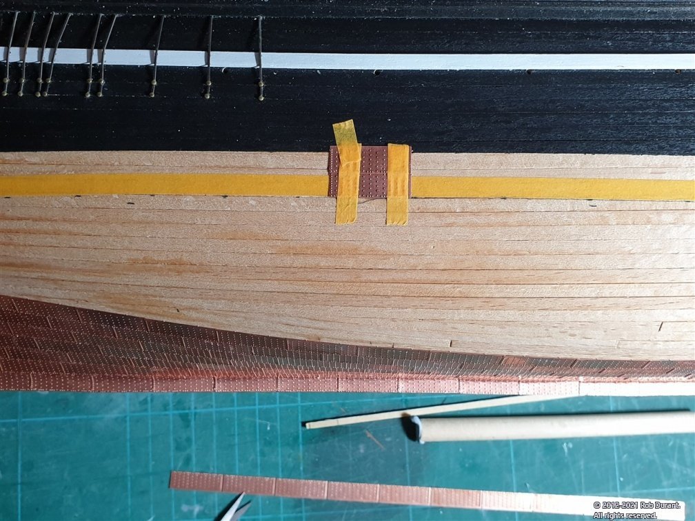
Thanks for all the likes and encouragement. I thought it might be helpful to some if I described in a little more detail how I'd planned out the bands along the top of the plating, when the plates are all laid from the keel up. It presents an interesting challenge, because the shaped tiles must be laid first, then the bands along the top which overlap them. All must be done leaving enough space for the top plates to overlay the lower, and leaving a smooth waterline, and without too much distance between the plating below the bands, and the waterline so that messy gaps are left. In addition, one can't simply leave full tiles underneath the top bands as they have raised rivet detail which will raise them unevenly. Hence they must be trimmed. I wondered whether I might hammer down the detail, but I was unconvinced that I'd manage to do that on the rivets in question without completely destroying the visible area of the tiles. Here's how I managed it. I measured the width of the bands at the top, and marked that width down from the waterline minus two millimetres. That gave me the line I wanted the plating to finish at below the bands. Once the lower plates reached that line they are now being cut to follow that line. The lower band can then be started overlapping those plates slightly, and leaving 6mm for the upper band. Hopefully that makes sense. At each sense, I'm making sure I'm measuring again carefully and checking as I go. I'm using 6mm masking tape to keep a nice neat space for the top band (which are the tiles with rivets on the top AND bottom) to finish off. This should, hopefully result in a nice neat line. The waterline painted will be the guide for this. Here are the results so far... The first photo shows the lower plating cut to the pencil mark (which shows the bottom extent of the two bands, minus the overlap). The first two plates of the lower of the two top bands have been added, with the yellow masking tape giving a guide to make sure sufficient room is left for the top of the two top bands. The second photo is the same work but from the stern to show the sweep as it goes forward. And a couple of angles of progress so far. These plates are quite simply cut where necessary with little scissors, so with a little care the job is proving relatively straightforward. I've also realised that the photo etch tags can be easily cut with a scalpel to remove them from the main sheet without any bending. So that's now my preferred method of doing that. Once done, they are then trimmed and separated with tiny sewing scissors. Happy building! Rob
-
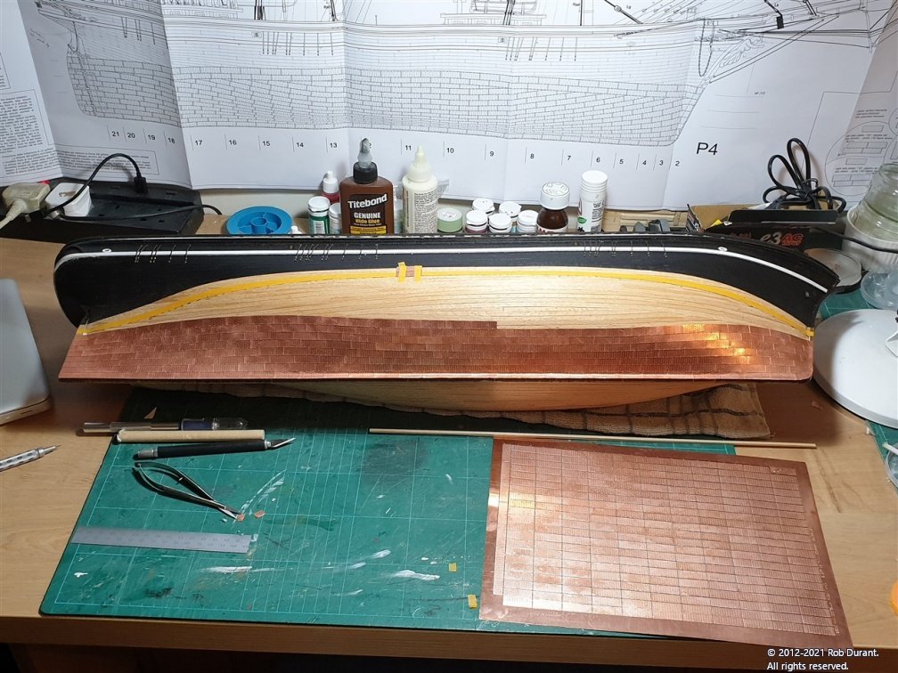
I've been gradually plodding along with the copper plating. This would have been faster, but I got distracted with another small kit, and took a holiday... The copper-plating has two rows that run at the top parallel to the waterline. I've used masking tape to mark the bottom of that band (with 2mm to play with), so that I know where to stop the lower bands. These lower bands will be cut to fit the lower edge of this masking tape, and then the two top rows added to finish the job. So the masking tape finishes 13mm below the waterline. It's worth noting that this isn't 13mm vertically, but 13mm as the plates are laid... a fairly different measurement by the time you get towards the stern.
-
Hi Tim Yes I am at Corsham Baptist. We planted a church 6 years ago just up the road and I spend most of my time serving that congregation. Ministry has had its fair share of challenges and unexpected opportunities over the past year. But I think we’re doing okay. Hope you, your family and your church are doing well too. I appreciate your prayers very much and have prayed for you this morning too. One of the appealing things about this hobby to me is that if I have a time when ministry doesn't allow any work to happen on the boat, it just wants patiently and I can pick it up again when I'm ready. Quite rightly family and faith come first I'm glad you like Ethalion. She's still under a plastic sheet waiting for a display case. Rob
-
From one time-poor church minister to another, that's a very handsome vessel you have there. The detailing around the stern quarter - especially the windows look very fine, and I really like the colour scheme with the copper bottom and the blue accents on the upper works. Do keep posting your progress Rob
-
A very good question. To be honest I don't know, but it sounds plausible. Perhaps someone here can tell us.
-
Very nice that jig seems to be producing very good results.
- 17 replies
-
- 2
-
-
- Cuauhtemoc
- Mexico
- (and 3 more)
