

woodrat
-
Posts
780 -
Joined
-
Last visited
Content Type
Profiles
Forums
Gallery
Events
Posts posted by woodrat
-
-
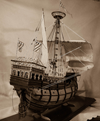
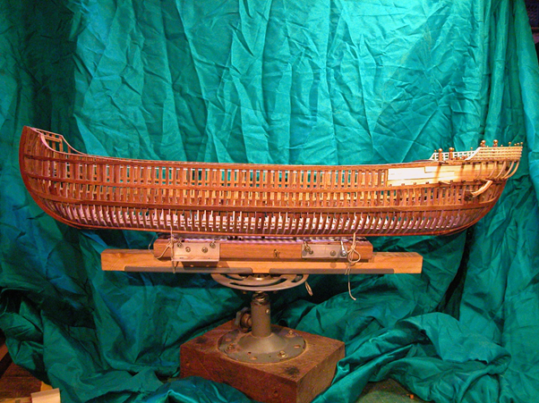
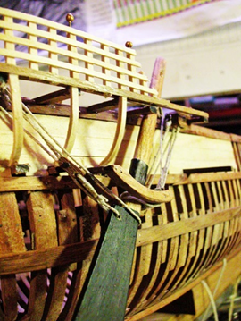
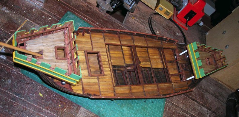
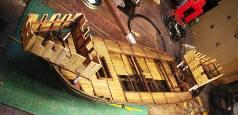
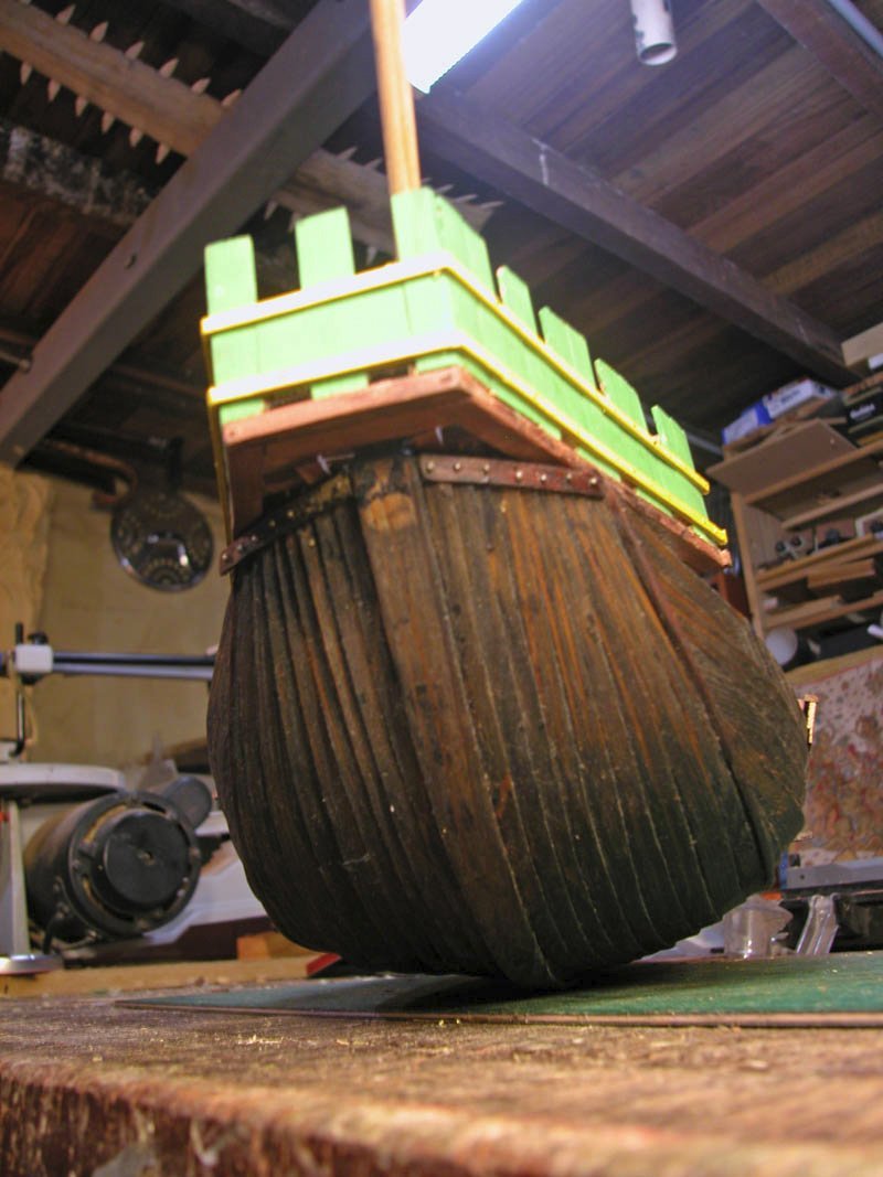
Well, that's the hull complete. I don't think the ship has turned out as outlandish as I thought it might. Any self-repecting gryphon would be happy to be transported in her. Now for some deck furniture, rigging and a mort of decoration.
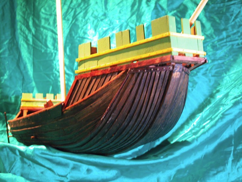
Cheers
Dick
- popash42, druxey, GrandpaPhil and 1 other
-
 4
4
-
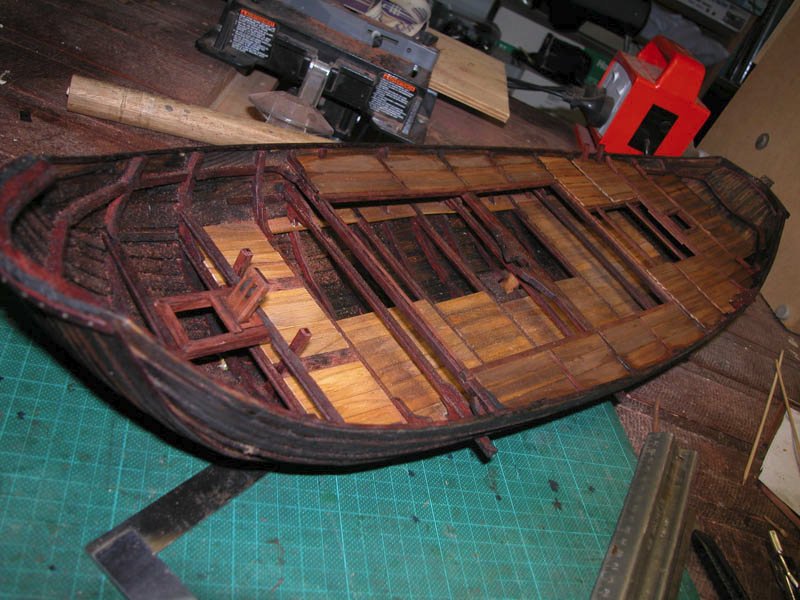
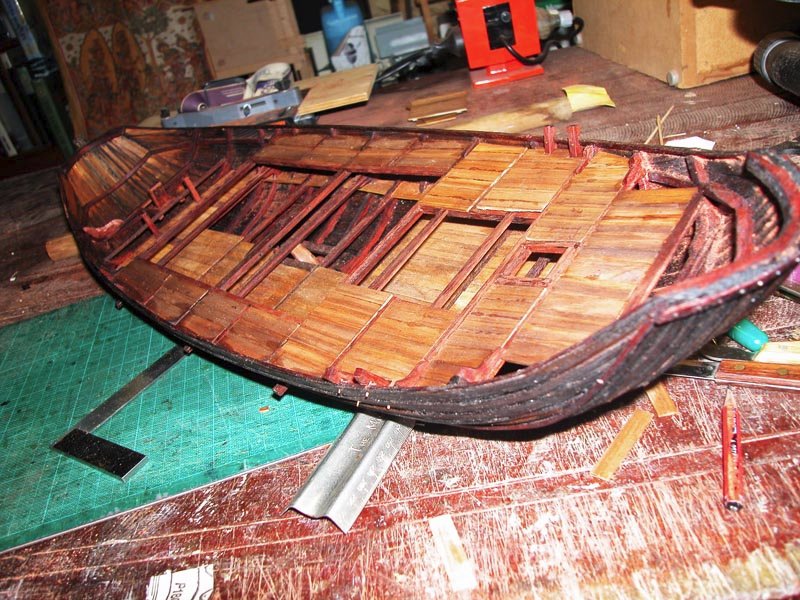
Summary of the Construction of the Hull
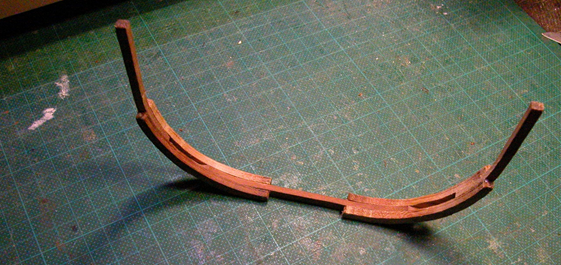
On a building board with the plan of the ship glued, the keel was erected.
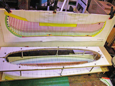
Stem and stern posts were scarfed onto the keel.
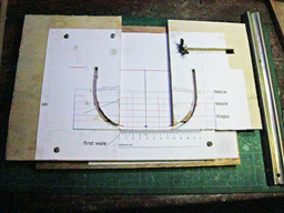
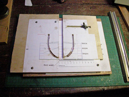
At this stage the shape of the master frame was determined by geometric technique of the manuscript Libro de Navigar.
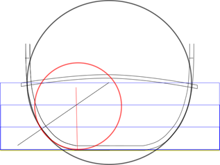
The master frame is fixed to the keel
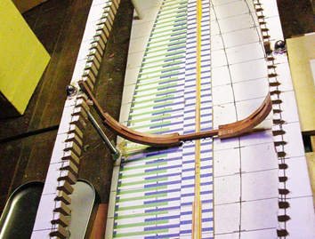
A special jig was made to allow assemblages of frames with different amounts of floor narrowing
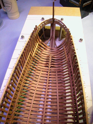
Tail-frames and every fifth frame attached to the keel.
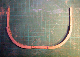
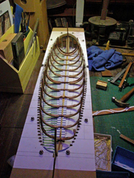
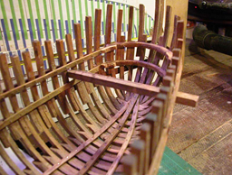
Intermediate frames are inserted to complete the main hull framing.
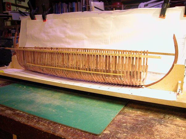
Ribbands between the hull, stem and sternposts are used to fashion the bow and stern frames.
Internal stringers and deck clamps are installed and longitudinal wales.
This completes summary of the framing of the hull
The Quarter Rudders
Mediterranean vessels of the 13th century followed the ancient practice of having two rudders on each of the vessel’s quarters. The shape of these rudders is well known from contemporary pictures and recent discoveries in the Black Sea and elsewhere have confirmed the accuracy of these pictures. In essence, the quarter rudders need to have a mechanism to allow raising and lowering of the rudder. For instance, when heeled over under sail it was a common practice to raise the weather rudder and to steer by the lee rudder. A tiller was slotted into the upper end of the rudder. In addition, because there is considerable lateral force on the rudder, this must be resisted. In order to allow raising and lowering and resist lateral force, a system of curved rudder guides was built into the quarter of the ship and rigging designed to achieve this. The rigging is shown diagrammatically and the rudder guides as constructed on the model::
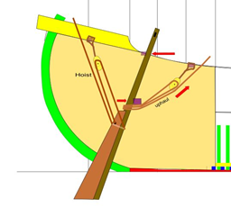
The rudder in raised position:
The timoneer’s position is in front of the sterncastle
The Deck furniture
The Pumps
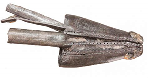
These ships were probably fitted with log pumps. So called because the longitudinal element was made from a single log hollowed out by large augers . The pump mechanism was and expanding leather cone lifted by hand and predating chain pumps by centuries.
This example was found in the Newport ship
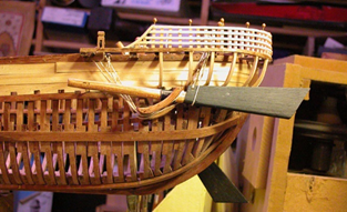
These are the pumps in the model
The Windlass
The use of simple windlasses is well attested but probably not capstans. I doubt that pawls were installed at this early stage.
Masting and Rigging of the Round Ship will be summarised in the next post
- bruce d, Vivian Galad, druxey and 5 others
-
8
-
Reconstruction of a Venetian round ship of the 13th century
Summary
Richard J Beaver
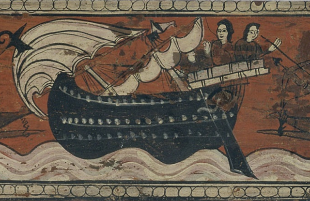
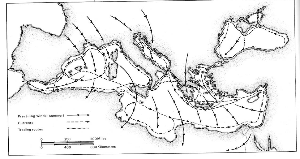
During the mediaeval period, Venice was a trading hub which dominated the Mediterranean and, despite numerous battles with its rivals Genoa and Pisa, Venice traded widely through the Mediterranean basin, up into the Black Sea and even sent trading vessels into the Atlantic as far as Flanders and the British Isles.
At the period we are dealing with most of its trade was conveyed in either merchant long-range galleys (long ships) for longer distances
or, for shorter hops, the round ship. It is this latter vessel that I wish to represent with a 1/32 scale model, built, as well as can be ascertained from the limited evidence, according to the original techniques used by Venetian shipwrights. Evidence was derived from rare manuscripts, contemporary paintings and illustrations and from the few wrecks of these ships that have been found.
The craft of the ship-builder was secret and passed on to family or trusted individuals. Woe betide anyone who stole or revealed the secrets of this craft! No plans were drawn up. The constructions and measurements were made using geometrical and arithmetic formulae. These were transferred to templates which were often no more than dozens of marked sticks which were stored in case a further vessel was required. For instance, the distance from the top of the bulwark to the main wale would be one marked stick and the width of a deck beam would be another.
The Round Ship or Nave Tonda was built skeleton-first and carvel-planked. It was lateen rigged on one or two pole masts.
The stem and stern posts were drawn using simple Euclidean geometry and attached to the keel by simple scarfs. The keel lengths, beam width and depth of hold were also established using geometric techniques adjusted according to the owners special requirements.
Each frame of the “skeleton” was modelled on a “Master-Frame” and consisted of a flat floor timber, two futtocks and two top-timbers fastened with iron bolts.
No trenails were used in the construction. Having established the length of the vessel, the number of needed frames was calculated. Having determined how much the frames would narrow fore and aft, a geometric technique such as the “Mezza Luna” (there were others) was used to produce a smooth narrowing between the Master Frame and the two Tail-Frames (the last frames with a true floor, one at the fore and one aft).
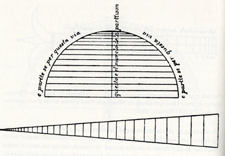 Each frame was then constructed with progressive narrowing of the floor. Every fifth frame was bolted to the keel and trued up.
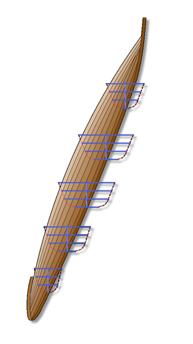
At this point, the frames were connected by longitudinal ribbands. The remaining intermediate frames were then installed. Ribbands were extended to the stem and stern posts. By direct measurement the bow and stern framing was constructed. After completion of framing, planking proceeded (by the Guild of Caulkers) using carvel planking, well caulked. External wales, internal longitudinal stringers, keelson and ceiling were installed. Lastly, deck beams were installed.
In order to construct the model, I used the framing plans of the Contarina 1 shipwreck discovered in 1898 and fully measured.
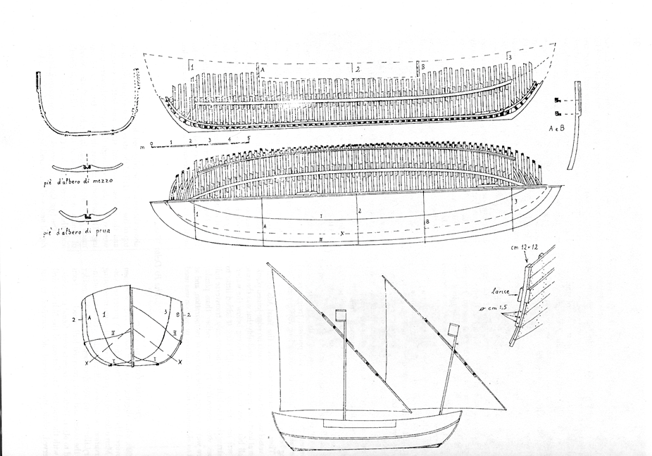
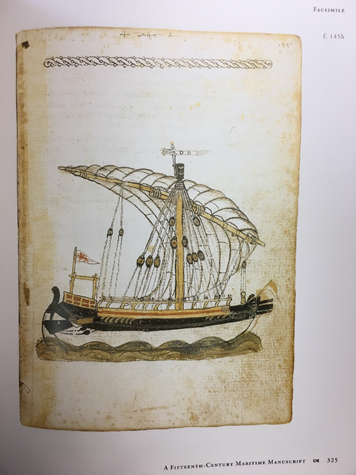
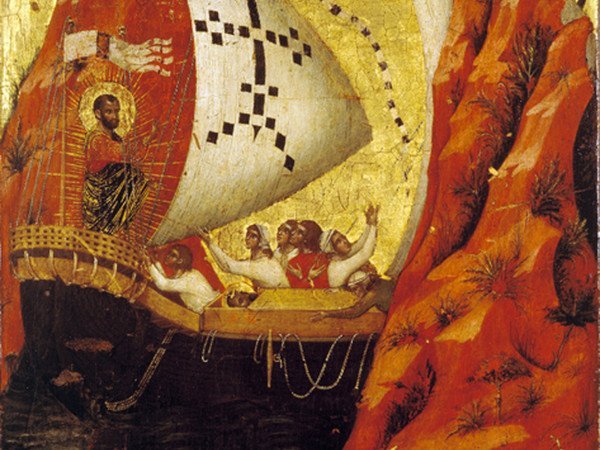
The overall dimensions were those given in a contemporary manuscript by Michael of Rhodes which has been fully published and translated. Lastly the superstructure was based on a painting by Veneziano in the St Mark’s Basilica ( the Pala d’oro).
Summary of theConstruction of the model
to follow in next post
-
-
1 hour ago, Louie da fly said:
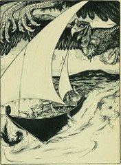
And of course the gryphons are in case you want to do a bit of elephant hunting. (Is that a hulc I see in the background?)
It certainly is, Steven. With a large gryphon landing pad on the sterncastle.
But I thought it was the Roc that carried away elephants.
and dropped rocks on ships
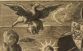
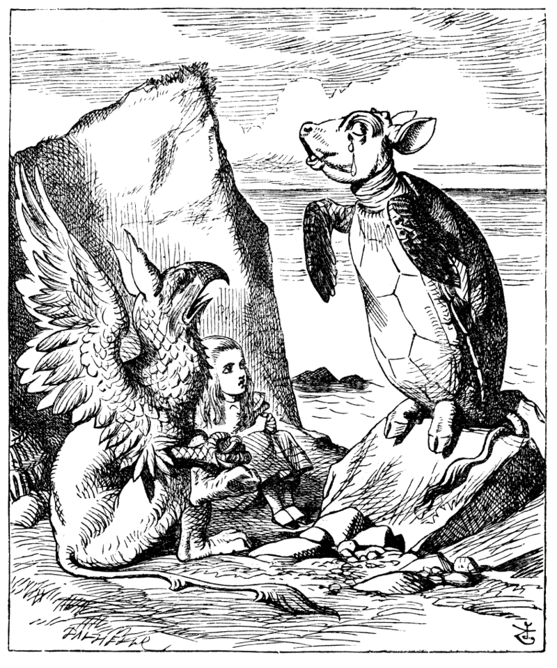
I do not think that gryphons (griffins is equally incorrect) have the strength to lift elephants and I quote as my source:
"in size and strength they resemble lions, but having this advantage over them that they have wings, they will attack them, and they get the better of elephants and of dragons. But they have no great power of flying, not more than have birds of short flight; for they are not winged as is proper with birds, but the palms of their feet are webbed with red membranes, such that they are able to revolve them, and make a flight and fight in the air; and the tiger alone is beyond their powers of attack, because in swiftness it rivals the winds." Flavius Philostratus, The Life of Apollonius of Tyana, translated by F. C. Conybeare, volume I, book III.XLVIII., 1921, p. 333.
And if Tenniel is to be believed, they are much too genteel.
Cheers,
Dick
- GrandpaPhil, mtaylor and druxey
-
2
-
 1
1
-
To avoid cluttering Stevens log I have made some speculations on beams and decks in my hulc log
Dick
- mtaylor, Chuck Seiler and Keith Black
-
3
-
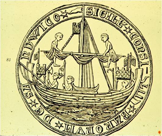
Until we find and excavate a nef with its upper works preserved enough to directly observe, any reconstruction is frumious. For my two bobs worth (i.e. two shillings worth, i.e. not worth much), however, I observe from the seals that many of these vessels have 3 through beams and the middle of which is forward of the mast where most force would be applied. The other two are forward and aft of this and are obviously meant to take a lot of strain. Indeed, the Sandwich seal shows the boat stored between the middle and aft beam. This suggests to my congested brain that there is a foredeck and and an aft deck supported on the fore and aft beams respectively. This would leave a large storage area between the fore and aft throughbeams which could be planked over, support a main hatch or left open ( for instance to transport horses and griffons). If left open (to allow griffons to see over the side as they have long necks) gangways may be needed to allow crew to go backwards and forwards and avoid griffons.
I have attempted to show this in my spurious imagined hulc . I have also joined planks together and made them into removable platforms which sit between the rabbets of my cross beams. This would simplify access to space under decks.
Cheers
Dick
- mtaylor, Chuck Seiler, druxey and 1 other
-
4
-
3 hours ago, Louie da fly said:
don't think I'll be putting "nail dots" in - I doubt that they would be visible at this scale. I think a lot of people add these kinds of details unnecessarily, often far too big.
I tend to agree, although many wouldn't. I made the same decision for the spurious hulc. The hulls were often blackened by pitch or other resins so nail heads would not show up well. When I was a lad and doing plastic aeroplane kits they often put in every rivet at 1:72 scale and all the dots made the plane look like it had smallpox. Later the kit tended not to have them. Looking grand, Steven.
Dick
-
-
4 hours ago, Tony Hunt said:
It raises the question about when the practice of using gains was first developed?
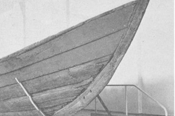
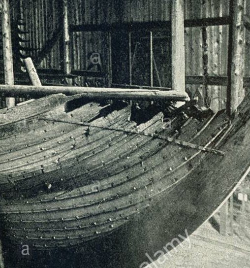
I'm not sure this helps. The Nydam Ship from the western Baltic has been dated to circa 320 CE. If I am interpreting the photos well the clinker overlap seems to be maintained to the rabbet. So the use of gains probably postdates this
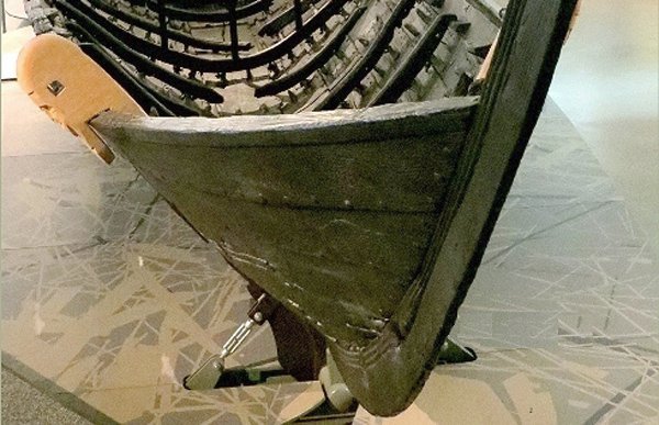
The Gokstad faering uses a different method again. So they were obviously experimenting
Dick
- Louie da fly, mtaylor, GrandpaPhil and 2 others
-
5
-
Thank you for all the likes. Nearing completion of the hull and castles. Quite a few seals show bowsprits. These are not in the centre but offset to one side . This will allow unobstructed access to the stem for the forestay. The bowsprit is mainly for leading the bowlines to the mainsail. Staysails and jibs weren't used to my knowledge. The bowsprit necessitates some imaginative framing in the forecastle and is why I have left decking till the very last. Note the scuttle allowing ladder access to the castle from the foredeck. This ladder would be pulled up if the waist were boarded.
Cheers
Dick
-
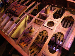
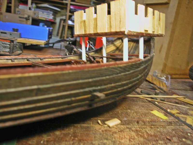
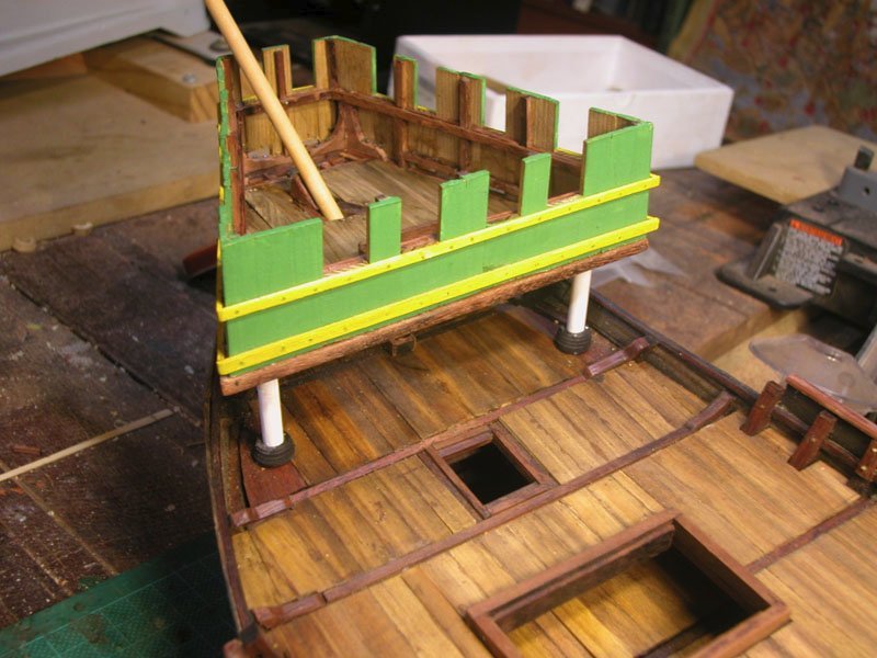
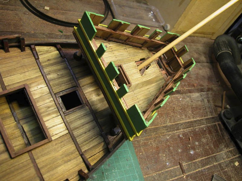
The castles prior to decoration.
 the sterncastle
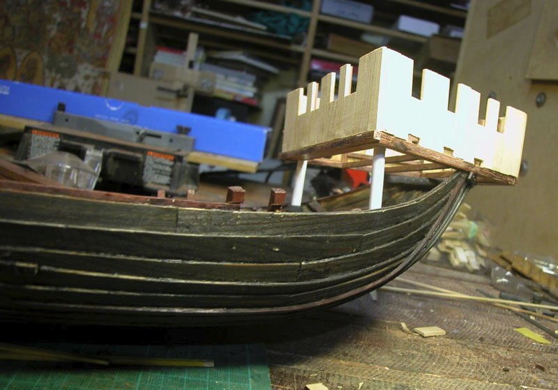 the forecastle
castle decking and access scuttles to be added
Cheers
Dick
- Brinkman, Roger Pellett, druxey and 4 others
-
7
-
Cometh the Banana Boat.
Thanks Steven and I look forward to your "nef"
Dick
-
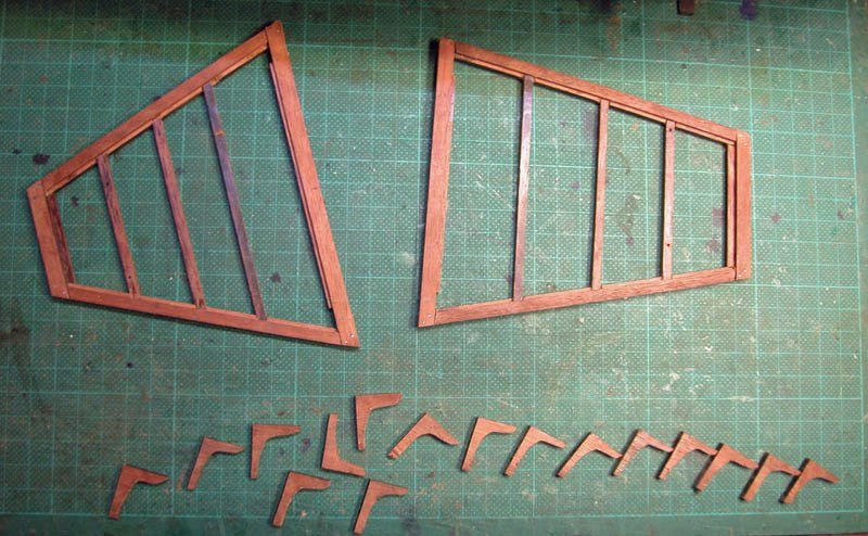
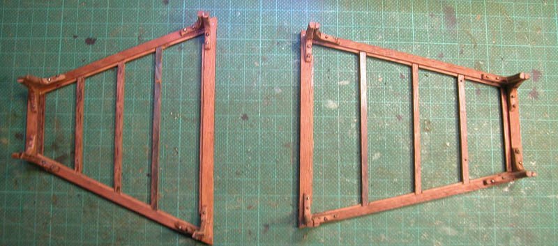
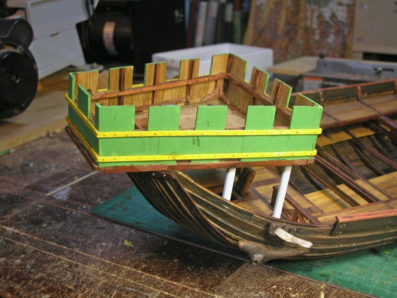
The following shows my interpretation of the possible framing of the fore and after castles. I believe that these should be strongly but lightly constructed as they would have to suffer the buffets of the sea as well as piratical assault while not making the vessel top heavy. Some models show somewhat flimsy castles.
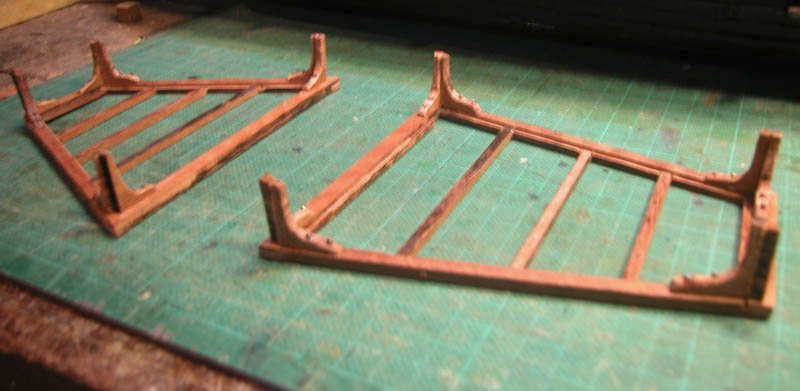
Cheers
Dick
- GrandpaPhil, mtaylor, Cirdan and 3 others
-
6
-
On 6/20/2021 at 1:49 PM, Kevin said:
sorry im so late to the party
Not a problem, Kevin. Welcome down the rabbit-hole. If you were to read the first few pages, you would understand that this ship comes from a somewhat Dodgsonian parallel universe. Nonetheless there is somewhat spurious evidence that such a ship (which we have called a hulc for lack of better names) may have existed and shipped cargo between England and the low countries in the early mediaeval period. We lack a wreck which could conceivably resemble this beast but, nil desperandum, what the heck!
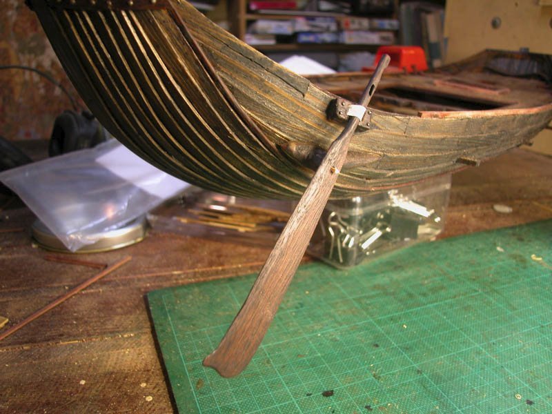
Here we have the quarter rudder, positioned on the "steerboard" side. The port or larboard side is reserved for the side of the wharf, where cargo is loaded. The rudder is closely modelled on the Vorsa rudder discovered in 1897 and probably a fairly new rudder which fell off because of withy failure (see previous posts). It is held against a wooden dome by the withy and the upper shaft is held against the hull by a strop of leather.
Cheers
Dick
- mtaylor, bolin, GrandpaPhil and 3 others
-
6
-
On 6/21/2021 at 12:50 PM, Louie da fly said:
Do you have some kind of idea of how you plan to construct your rudder-fixing? A diagram of what you have in mind would be very helpful.
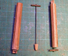
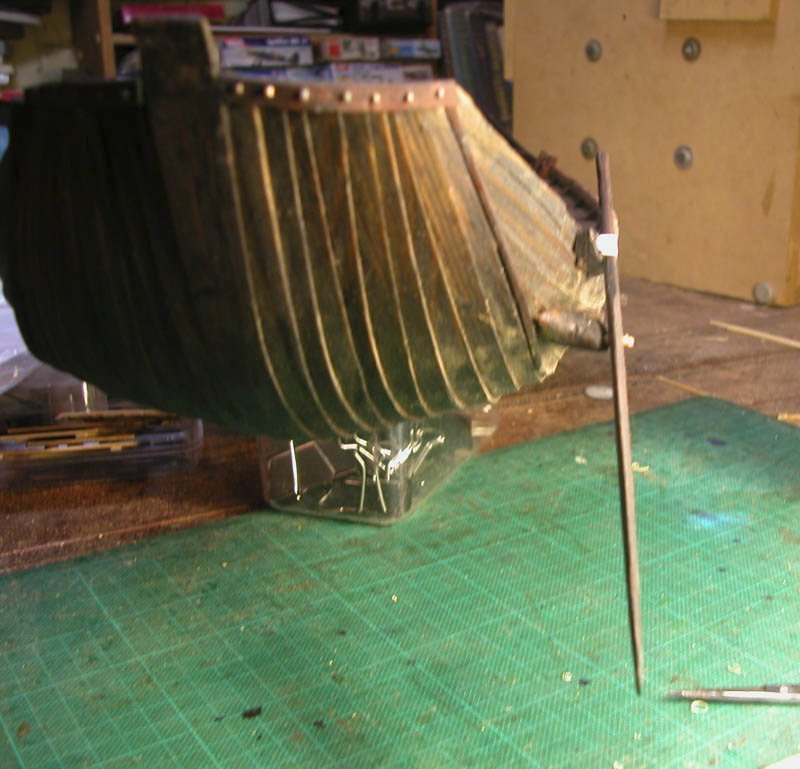
Yup. Better than a diagram. I built it.
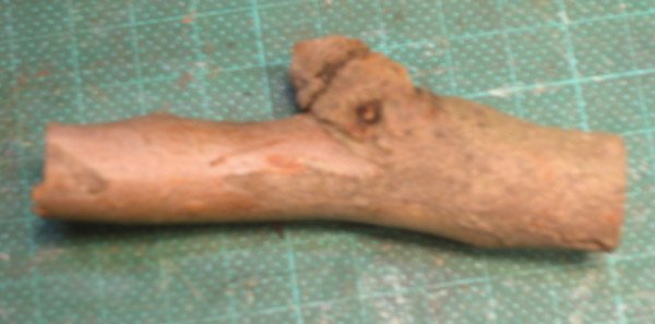
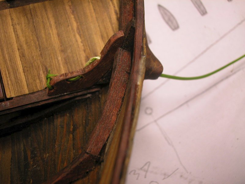
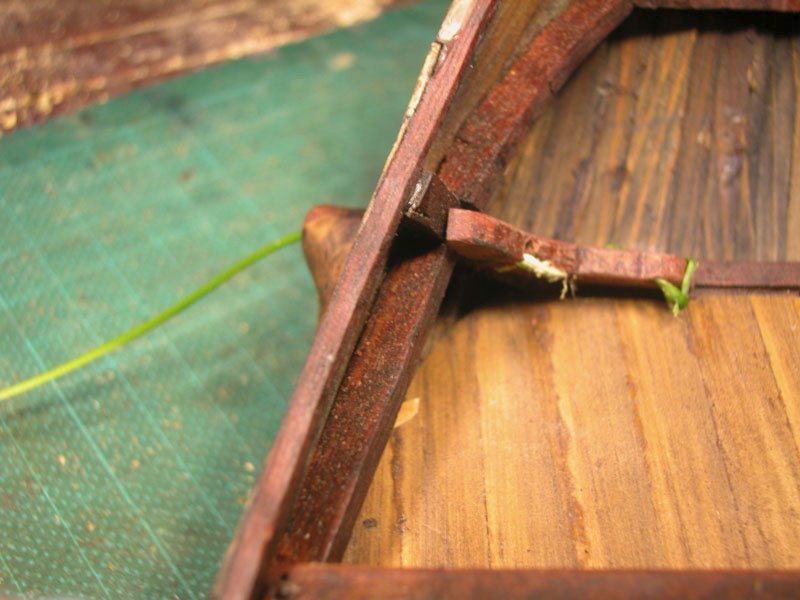
The hull fixture for the pivot needs to be solid. I carved it from a piece of fallen eucalyptus.
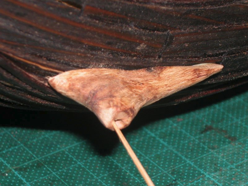
The internal fixture for weaving the withy is a solid extra knee with oblique channels for the withy. I tried to avoid acute angles so as not to stress the withy. Having carefully drilled a 2mm. channel throught he internal and external fixtures, I passed a length of green tendril from a creeper in the garden which was easily able to be tied in a knot
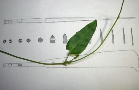
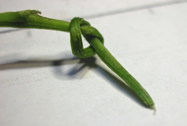 and remained strong.
After I will have attached the rudder, the withy will be tensioned with a wedge.
As this is an imaginary vessel, I allowed my imagination free rein.
Cheers
Dick
- druxey, GrandpaPhil, mtaylor and 1 other
-
4
-
The problem is how to tension the withy so that it holds the rudder to the side of the hull tight enough to resist the lateral pressure on the rudder and yet allow easy release of that tension so the rudder can be raised to avoid damage. Rope apparently stretches when wet and was found not to suit, so a withy was used.
Hurdle fences are constructed with withies made of willow or hazel. Note the variation in thickness of the withies. Presumably if they are small diameter and green they can be bent around corners more readily. Anyone have experience "with" withies?
Dick

T

- GrandpaPhil, mtaylor, popash42 and 1 other
-
4
-
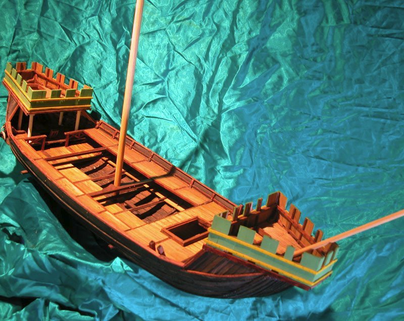
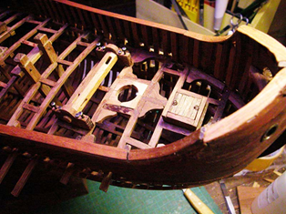
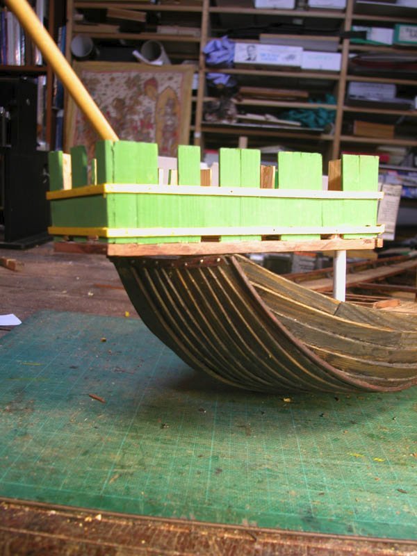
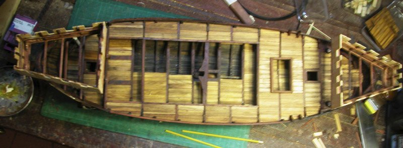
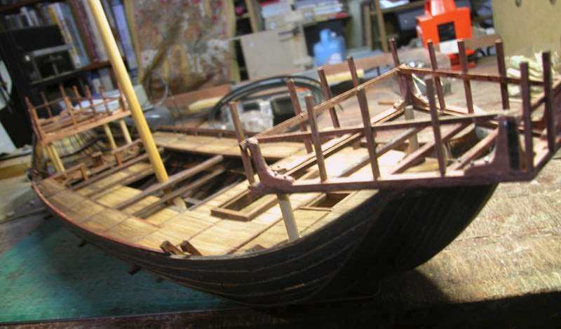
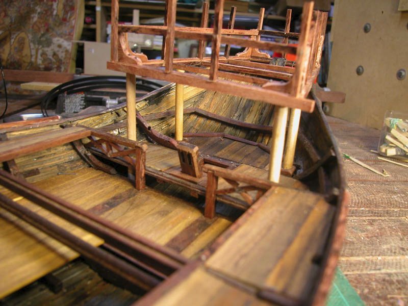
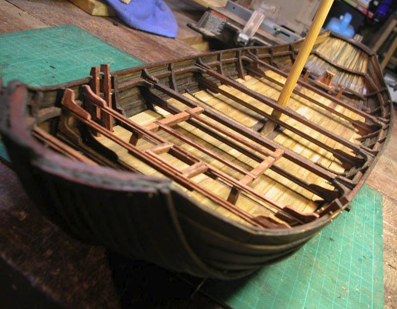
Gangways are installed and some carpentry at the poop. Remember that there will be castles (one for the Red Queen and one for the White Queen. May they never meet!)
Dick
- popash42 and GrandpaPhil
-
2
-
Gangways have been installed to allow easy access from the forecastle to the aft mechanisms and poop.
I have a cunning plan to suggest how the rudder can be tensioned via a withy ( a narrow flexible willow branch). The withy was used to hold the rudder against the hull and resist the lateral forces acting to push the rudder away from the hull. Rope was not used because it would tend to stretch when wet whereas the withy would remain taut. Also the withy would need to be able to be loosened to allow raising of the rudder.
cheers
Dick
- Chuck Seiler, bolin, mtaylor and 5 others
-
8
-
-
1 hour ago, Louie da fly said:
Particularly for a vessel that may never have existed!
I have seen many more imaginary and fanciful "reconstructions" of famous ships that definitely existed, such as Santa Maria and the Golden Hind, but never in the strange manifestations offered by many kit manufacturers. I am at least honestly guessing at what may have been and at the end of the task will have an attractive vessel on the mantle-piece. As has been stated in this log, experimental archaeology is its own justification and can shine light on the past that shipwreck retrieval archaeology cannot always achieve.
As an example of what experimental archaeology can achieve, I would point out your excellent reconstruction of the byzantine dromon and encourage others to take on such projects which are outside the mainstream of ship-modelling. Do we really need any more imaginary models of famous ships?
Grumpily yours
Woodrat
- Roger Pellett, druxey and mtaylor
-
2
-
 1
1
-
-
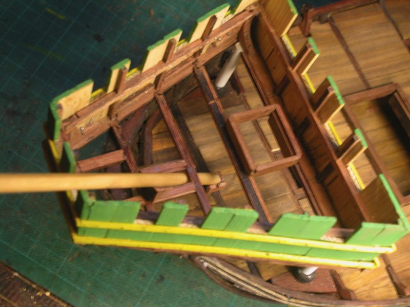
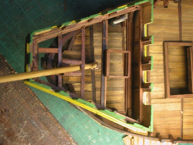
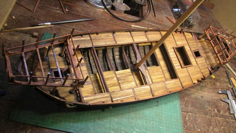
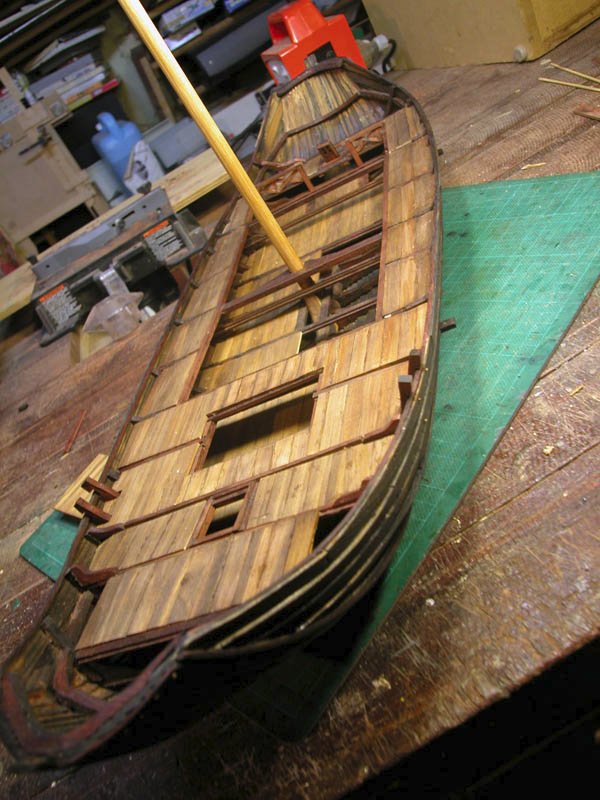
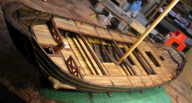
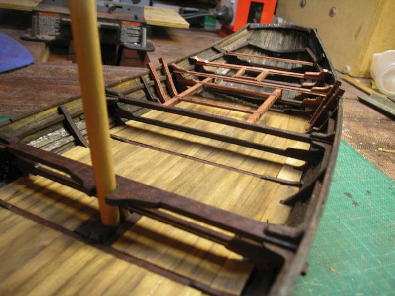
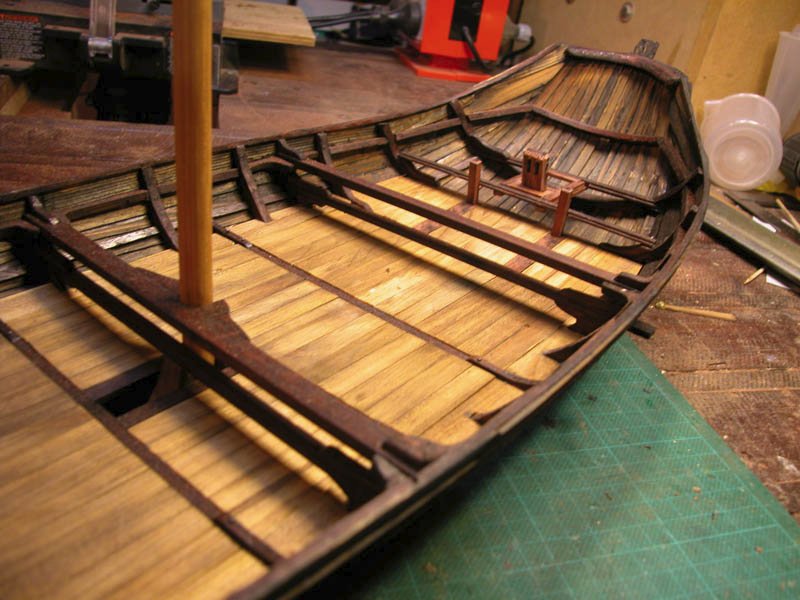
The lowest deck has been fitted. I have done this in removable panels. This would have been necessary to get access to the bilge for cleaning and repairs, especially if transporting horses.
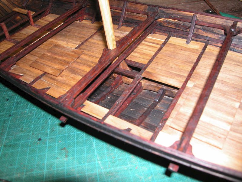
Cheers
Dick
- Louie da fly, druxey, GrandpaPhil and 3 others
-
5
-
1
-
Why,sometimes I've believed as many as six impossible things before breakfast.
- mtaylor, Louie da fly and druxey
-
2
-
 1
1

The Elusive Hulc by woodrat - FINISHED - 1:32 - plank-on-frame - a speculative reconstruction of a mediaeval merchantman
in - Subjects built Up to and including 1500 AD
Posted
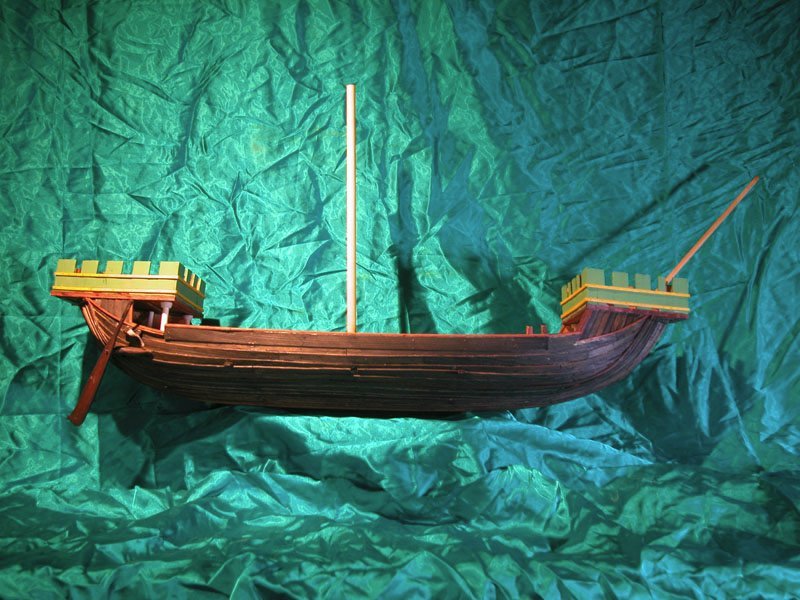
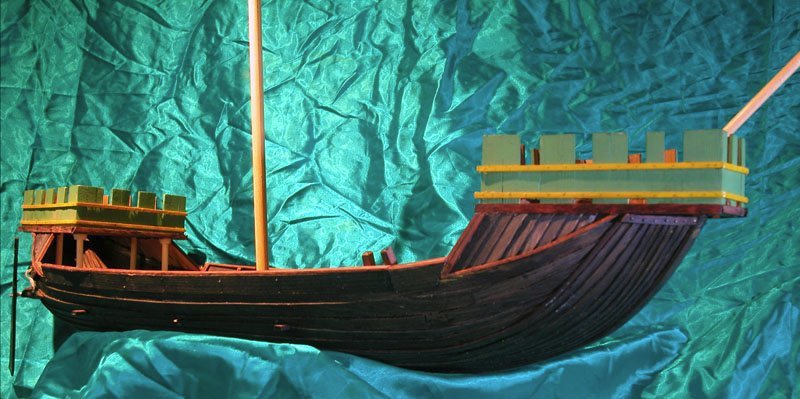
Well........ I did satisfy myself that this iteration of an hulc was buildable using techniques in common usage during the 13th century and earlier. The vessel ended up being quite beamy and capacious as would suit a merchant transport. This could suggest that hulcs may have developed from riverine vessels and barges used throughout western europe since roman days. The carrying capacity would have been superior to cogs and maybe even knaars. I am satisfied that horses ( although probably not gryphons) could have been transported in something analogous to this as seen in the Bayeux Tapestry.
The lack of keel and flat bottom would suit the vessel to quiet and more shallow waters or estuaries. I don't know how good a sailor it would be in the open ocean. With appropriate ballasting it may have been stable enough for crossing of the North Sea. The reverse clinker is likely to have reduced leeway because of the increased lateral resistance supplied by the exposed upper edge of the planking. This may also have reduced the tendency to roll with beamy seas.
It is unlikely that any nautical engineers would be interested enough to test this scientifically, but maybe if a reverse-clinker vessel were found....?
Anyway, it has been sort of interesting. The next build will definitely be one that has been fully excavated and , I think, not represented in MSW, The Nydam Ship.
Cheers
Dick