

woodrat
-
Posts
818 -
Joined
-
Last visited
Content Type
Profiles
Forums
Gallery
Events
Posts posted by woodrat
-
-
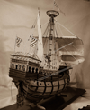
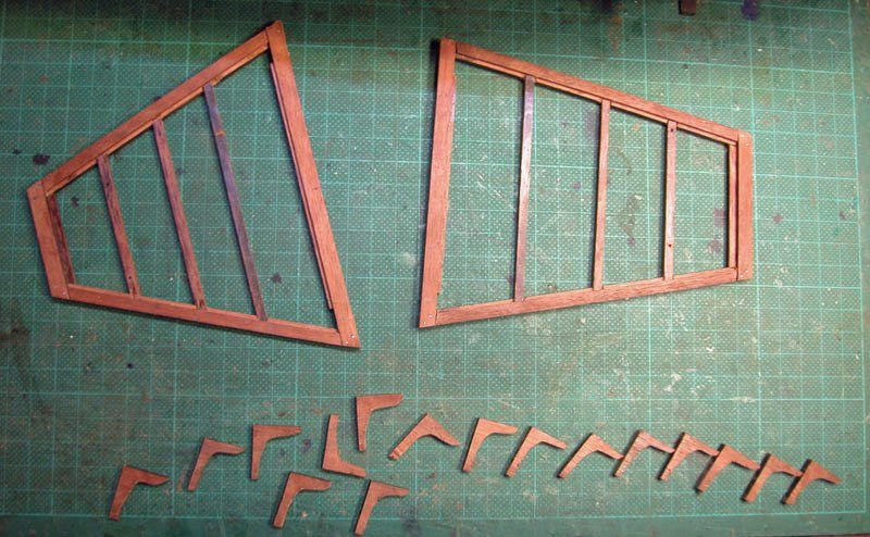
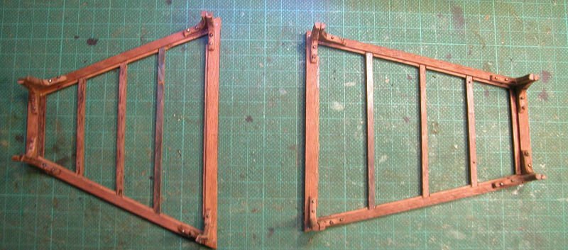
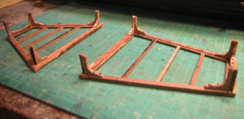
The following shows my interpretation of the possible framing of the fore and after castles. I believe that these should be strongly but lightly constructed as they would have to suffer the buffets of the sea as well as piratical assault while not making the vessel top heavy. Some models show somewhat flimsy castles.
Cheers
Dick
-
On 6/20/2021 at 1:49 PM, Kevin said:
sorry im so late to the party
Not a problem, Kevin. Welcome down the rabbit-hole. If you were to read the first few pages, you would understand that this ship comes from a somewhat Dodgsonian parallel universe. Nonetheless there is somewhat spurious evidence that such a ship (which we have called a hulc for lack of better names) may have existed and shipped cargo between England and the low countries in the early mediaeval period. We lack a wreck which could conceivably resemble this beast but, nil desperandum, what the heck!
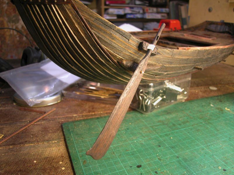
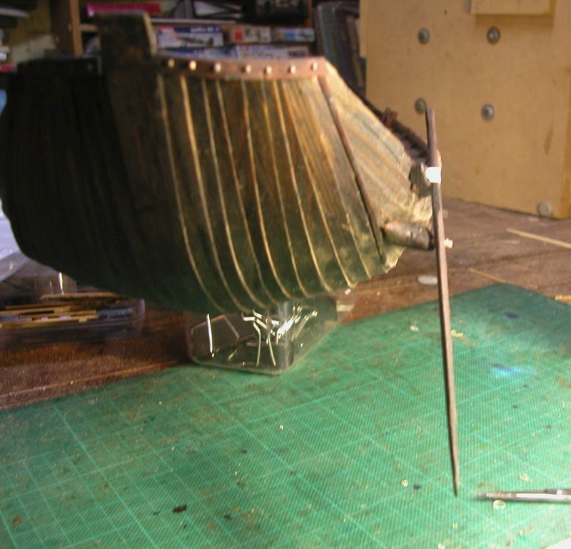
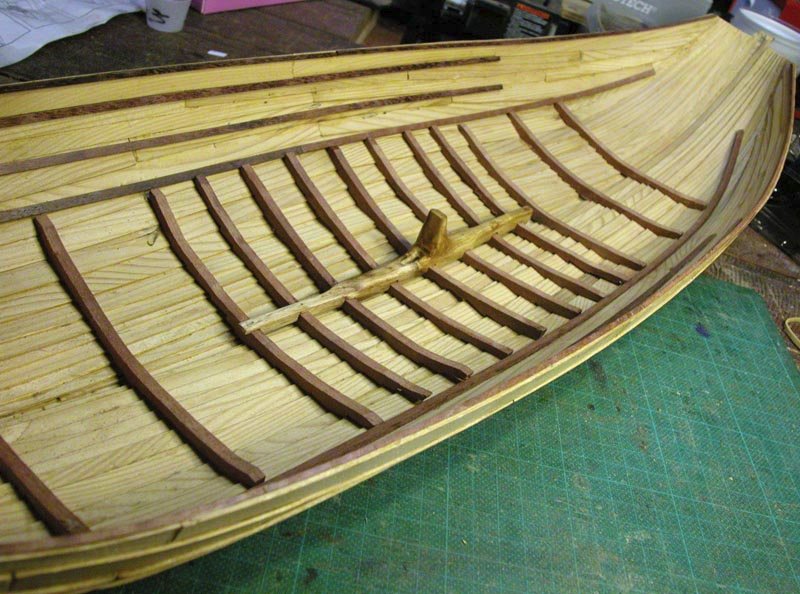
Here we have the quarter rudder, positioned on the "steerboard" side. The port or larboard side is reserved for the side of the wharf, where cargo is loaded. The rudder is closely modelled on the Vorsa rudder discovered in 1897 and probably a fairly new rudder which fell off because of withy failure (see previous posts). It is held against a wooden dome by the withy and the upper shaft is held against the hull by a strop of leather.
Cheers
Dick
- Cirdan, druxey, Louie da fly and 3 others
-
 6
6
-
On 6/21/2021 at 12:50 PM, Louie da fly said:
Do you have some kind of idea of how you plan to construct your rudder-fixing? A diagram of what you have in mind would be very helpful.
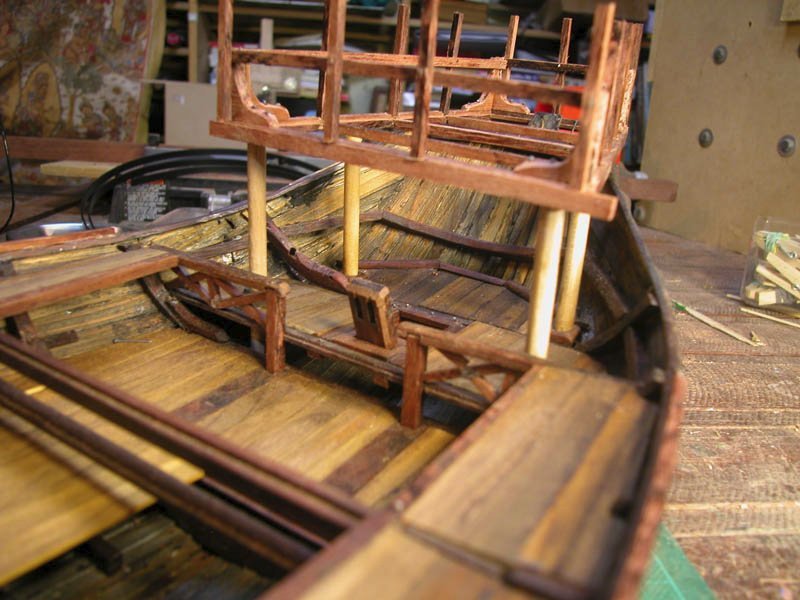
Yup. Better than a diagram. I built it.
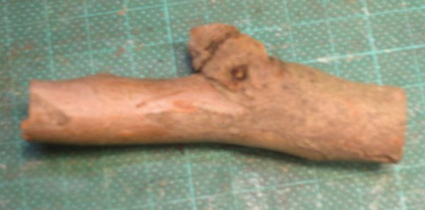
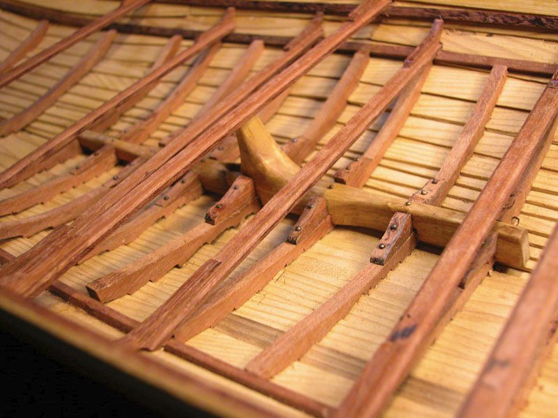
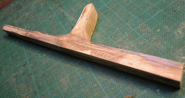
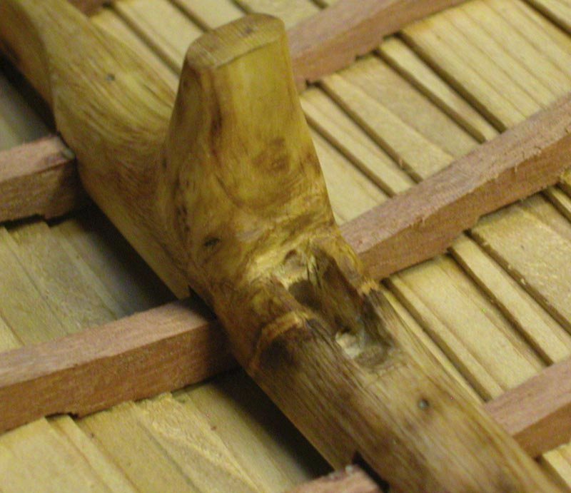
The hull fixture for the pivot needs to be solid. I carved it from a piece of fallen eucalyptus.
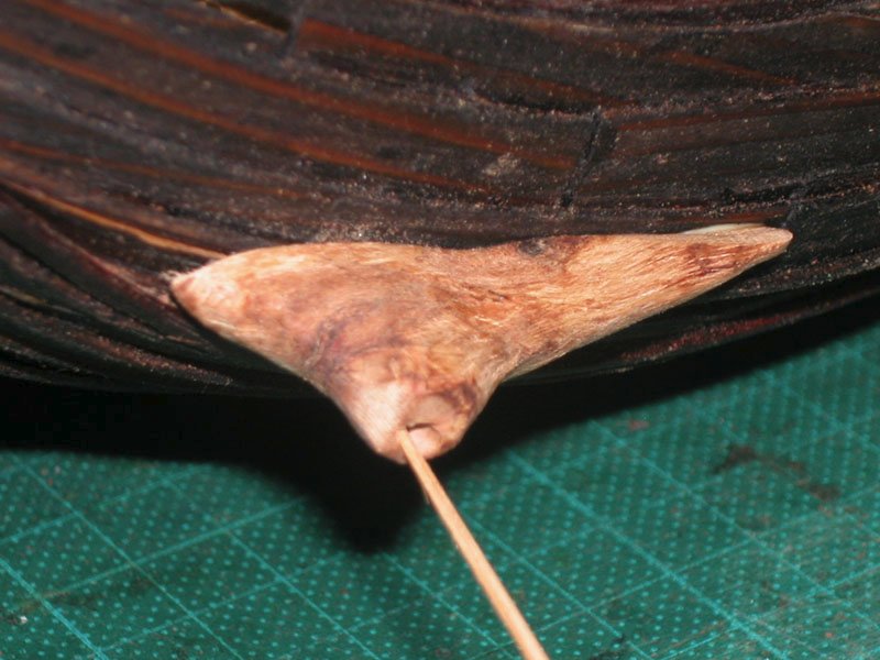
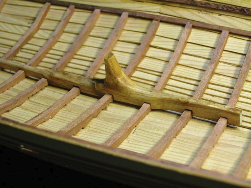
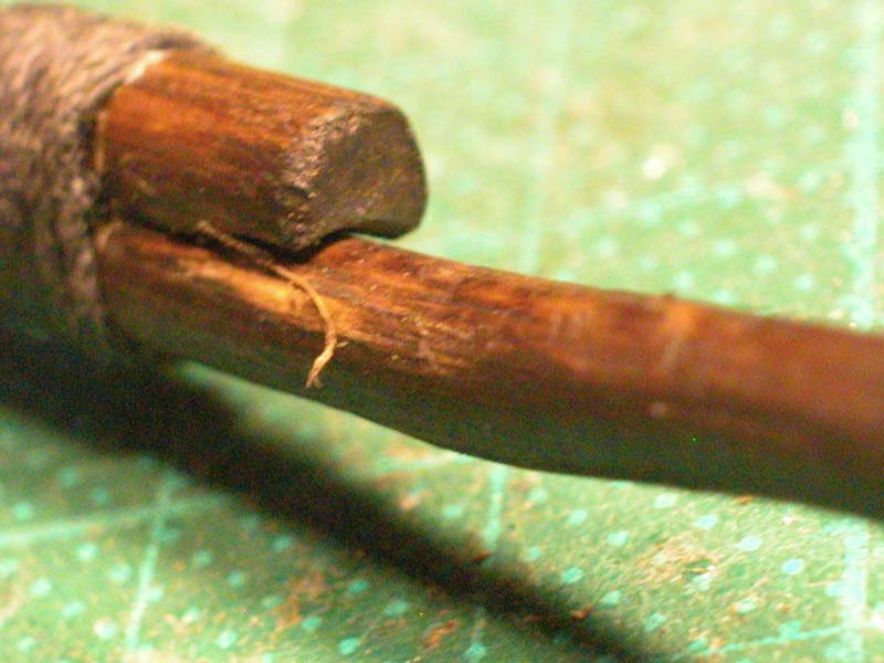
The internal fixture for weaving the withy is a solid extra knee with oblique channels for the withy. I tried to avoid acute angles so as not to stress the withy. Having carefully drilled a 2mm. channel throught he internal and external fixtures, I passed a length of green tendril from a creeper in the garden which was easily able to be tied in a knot
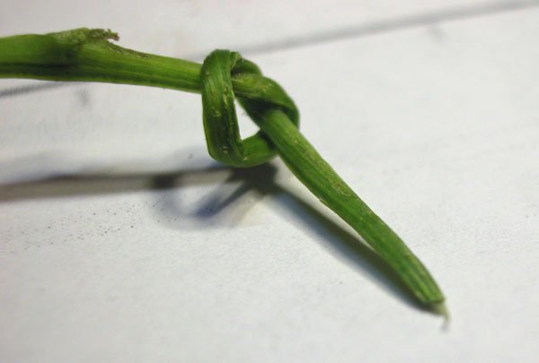 and remained strong.
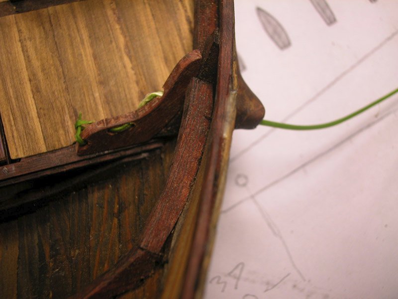
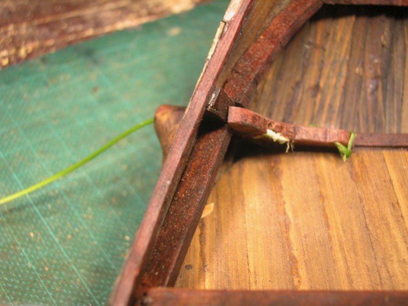
After I will have attached the rudder, the withy will be tensioned with a wedge.
As this is an imaginary vessel, I allowed my imagination free rein.
Cheers
Dick
- popash42, druxey, GrandpaPhil and 1 other
-
4
-
The problem is how to tension the withy so that it holds the rudder to the side of the hull tight enough to resist the lateral pressure on the rudder and yet allow easy release of that tension so the rudder can be raised to avoid damage. Rope apparently stretches when wet and was found not to suit, so a withy was used.
Hurdle fences are constructed with withies made of willow or hazel. Note the variation in thickness of the withies. Presumably if they are small diameter and green they can be bent around corners more readily. Anyone have experience "with" withies?
Dick

T

- mtaylor, GrandpaPhil, popash42 and 1 other
-
4
-
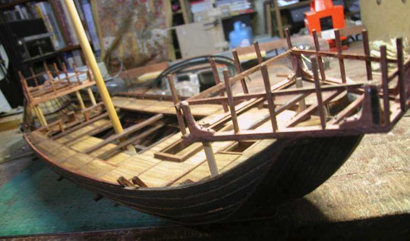
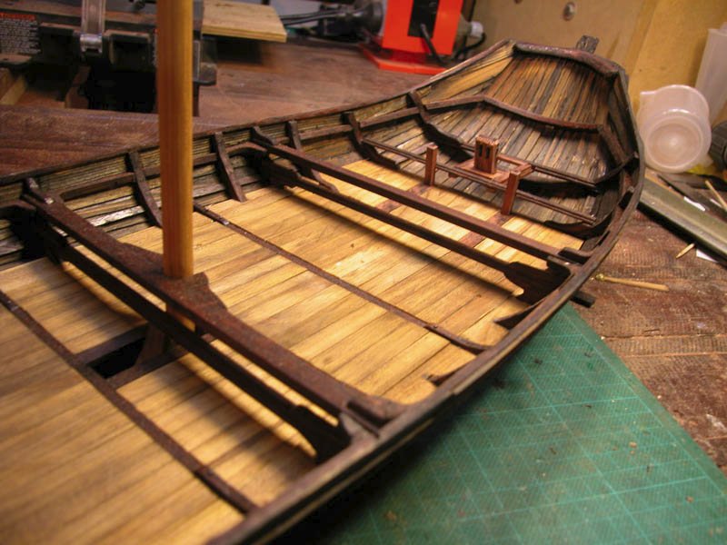
Gangways are installed and some carpentry at the poop. Remember that there will be castles (one for the Red Queen and one for the White Queen. May they never meet!)
Dick
- GrandpaPhil and popash42
-
2
-
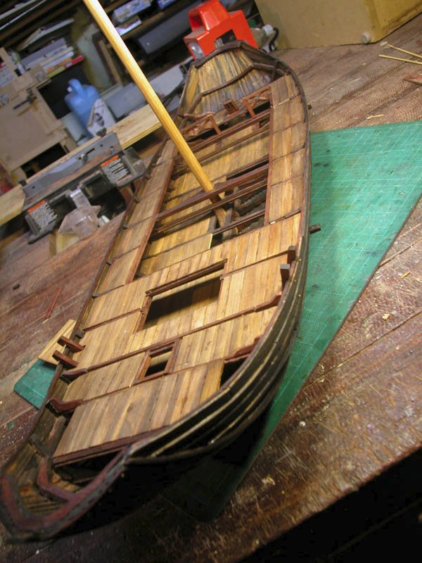
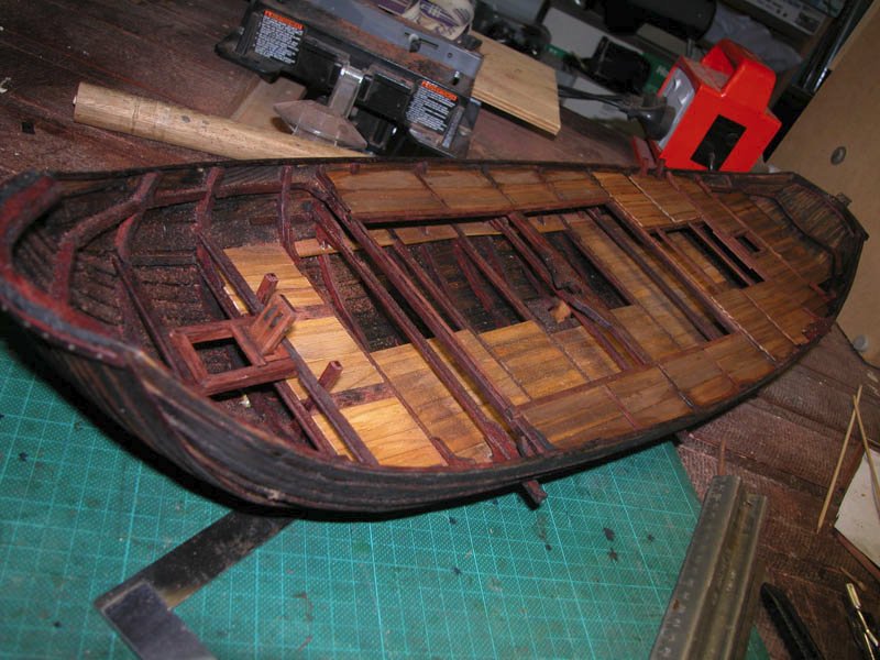
Gangways have been installed to allow easy access from the forecastle to the aft mechanisms and poop.
I have a cunning plan to suggest how the rudder can be tensioned via a withy ( a narrow flexible willow branch). The withy was used to hold the rudder against the hull and resist the lateral forces acting to push the rudder away from the hull. Rope was not used because it would tend to stretch when wet whereas the withy would remain taut. Also the withy would need to be able to be loosened to allow raising of the rudder.
cheers
Dick
- druxey, GrandpaPhil, davyboy and 5 others
-
8
-
-
1 hour ago, Louie da fly said:
Particularly for a vessel that may never have existed!
I have seen many more imaginary and fanciful "reconstructions" of famous ships that definitely existed, such as Santa Maria and the Golden Hind, but never in the strange manifestations offered by many kit manufacturers. I am at least honestly guessing at what may have been and at the end of the task will have an attractive vessel on the mantle-piece. As has been stated in this log, experimental archaeology is its own justification and can shine light on the past that shipwreck retrieval archaeology cannot always achieve.
As an example of what experimental archaeology can achieve, I would point out your excellent reconstruction of the byzantine dromon and encourage others to take on such projects which are outside the mainstream of ship-modelling. Do we really need any more imaginary models of famous ships?
Grumpily yours
Woodrat
- druxey, mtaylor and Roger Pellett
-
2
-
 1
1
-
-
-
Why,sometimes I've believed as many as six impossible things before breakfast.
- Louie da fly, mtaylor and druxey
-
2
-
 1
1
-
-
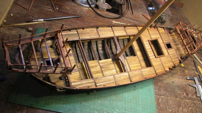
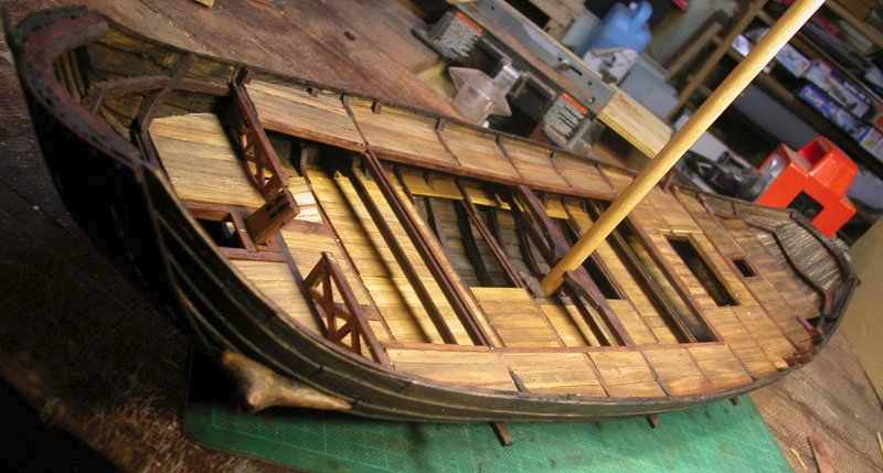
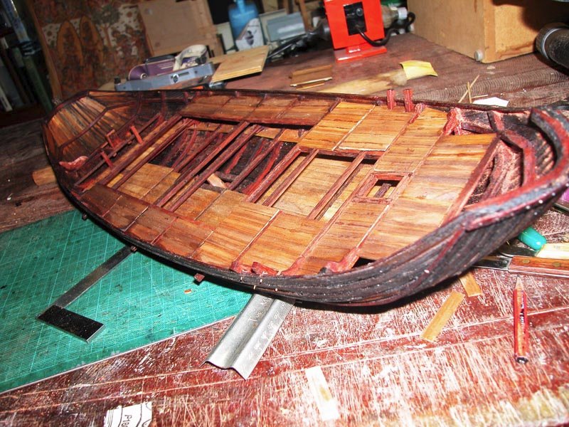
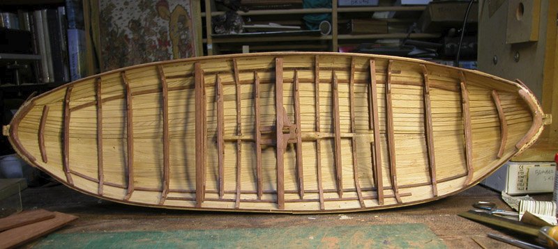
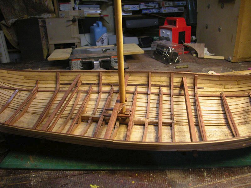
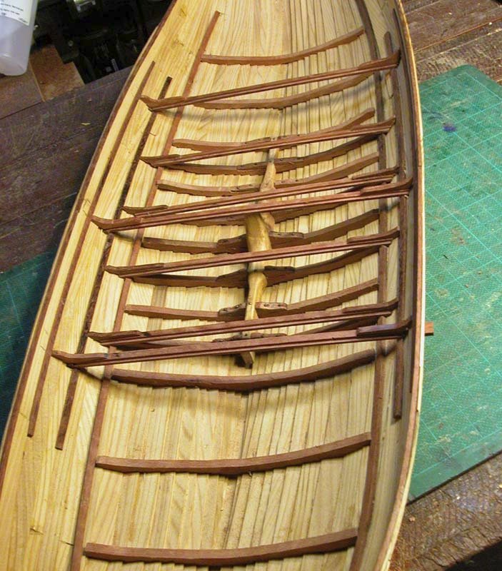
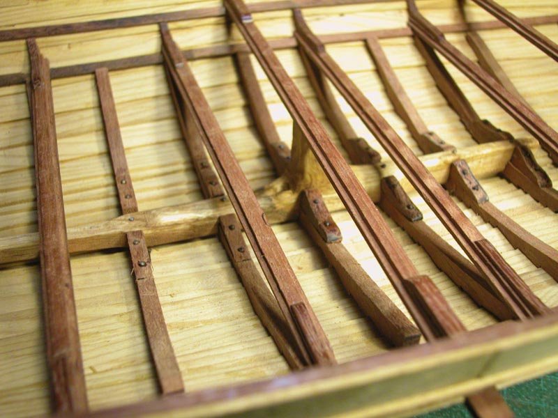
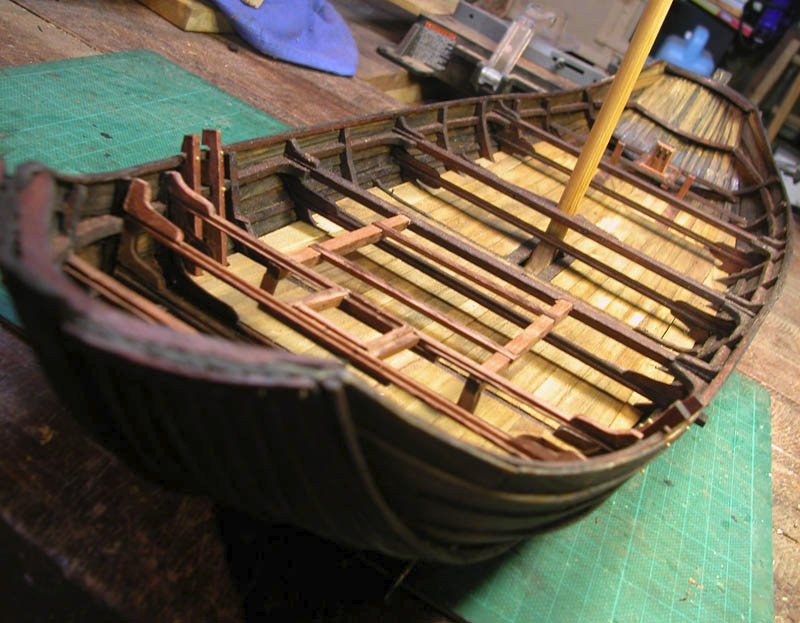
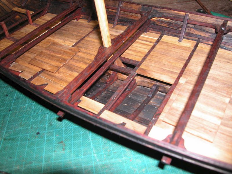
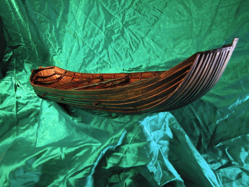
Hull framing nears completion with all frames trenailed to shell. The decks will be next. I plan to have a central cargo area which could transport horses if required.
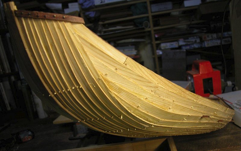
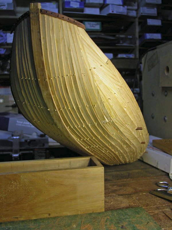
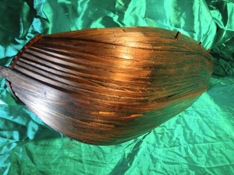
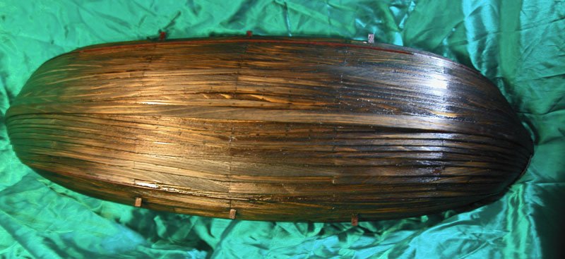
The scandinavian influence is obvious but the barge-like shape of the hull would increase cargo carrying capacity. The reverse-clinker leads to an increased resistance to leeway which makes it less necessary to have a deep keel. The side rudder however will need to be wide and deep in the water to add more lateral resistance. Also note that the reverse clinker creates a channel in the midline beneath the keelson where water can pool. There is no need then for limber holes in the frames and less likelihood of rot. Evacuation of water is simply done either by bailing or a log pump. I think I will install the latter.There is plenty of room beneath the keelson for water to move side to side as well as end to end. As there seem to be so many advantages to reverse clinker, I would be surprised if the clever shipwrights of the time did not at least try it.
Cheers
Dick
- GrandpaPhil, Roger Pellett, druxey and 6 others
-
7
-
2
-
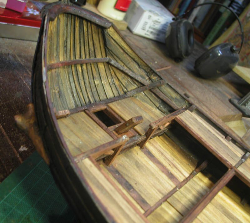
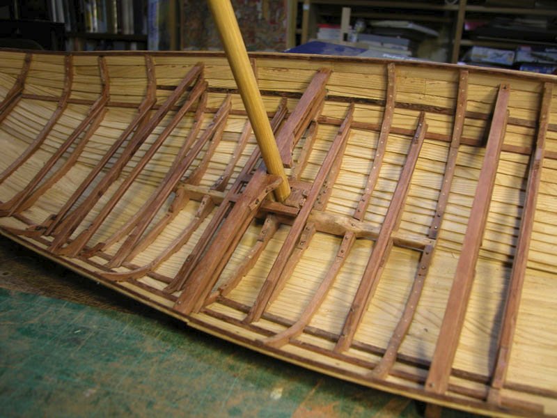
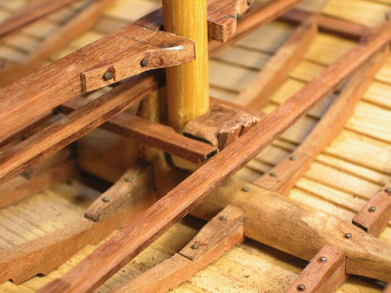
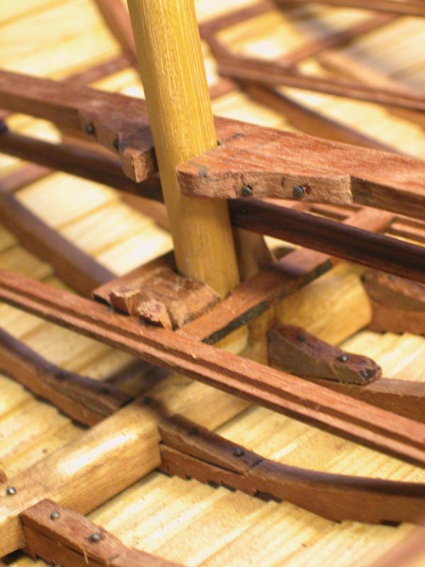
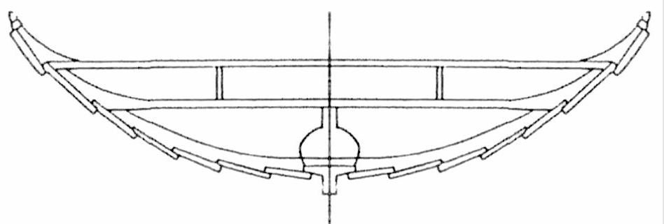
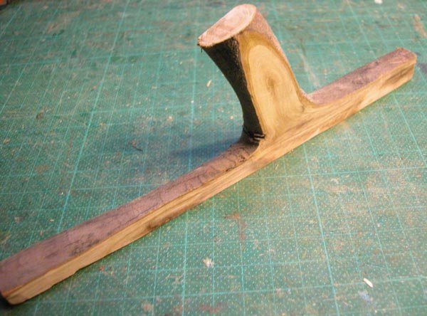
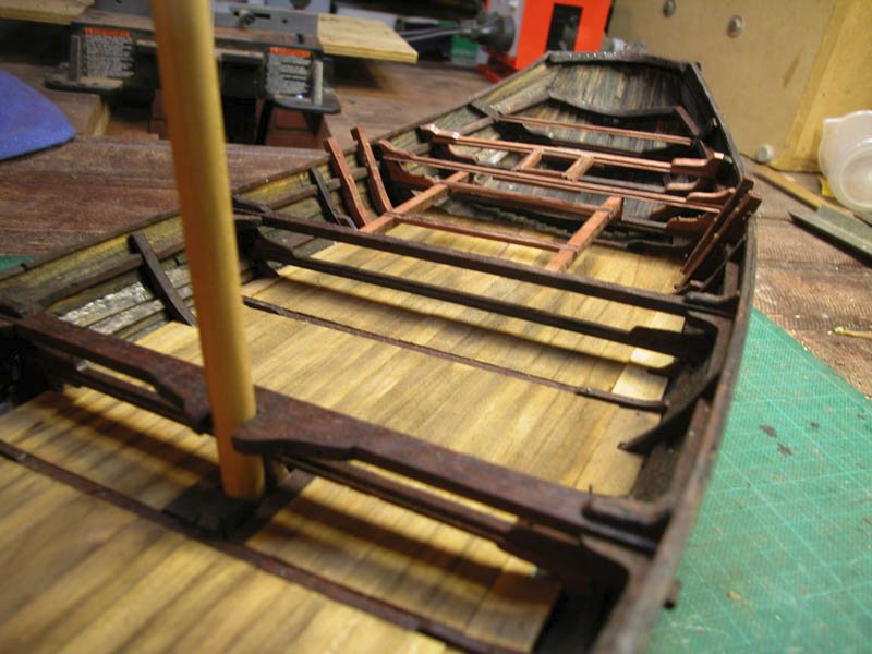
As there seems to be some discussion around nordic mast-steps, here is my take on it. The mast foot is introduced into the step slot at an angle then raised upright between the guides. The lower part of the mast abuts the vertical branch of the keelson. A rectangular timber is inserted behind the mast and wedged in place to hold and lock the mast . The mast is then lashed to the upper beam.

Cheerio
Dick
-
On 3/26/2021 at 12:59 AM, bolin said:
Seeing your keelson makes me wonder if I should reconsider how I plan to do it in my long ship. Beautiful work.
I cant tell from available information if the keelson/mast-step was preserved in the wreck of Helga Holm. If not then the reconstruction keelson has similarities to the skuldelev wrecks:
I would think that a chap of your skill would make short work of carving one from a nice piece of scandinavian wood
Cheers
Dick
-
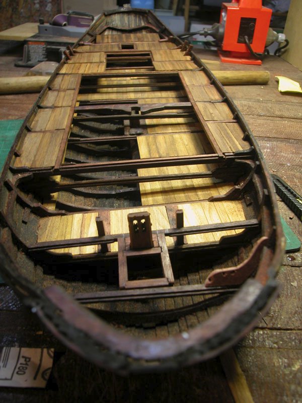
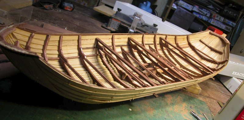
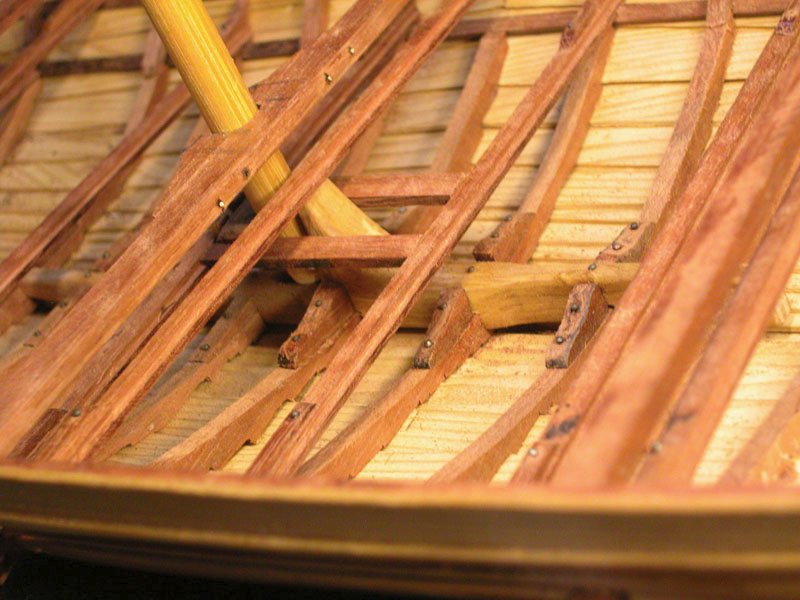
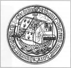
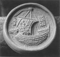
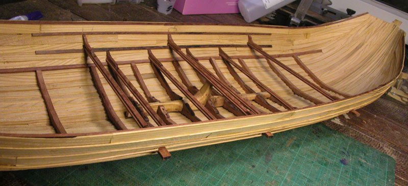
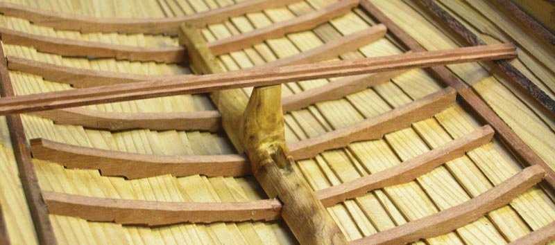
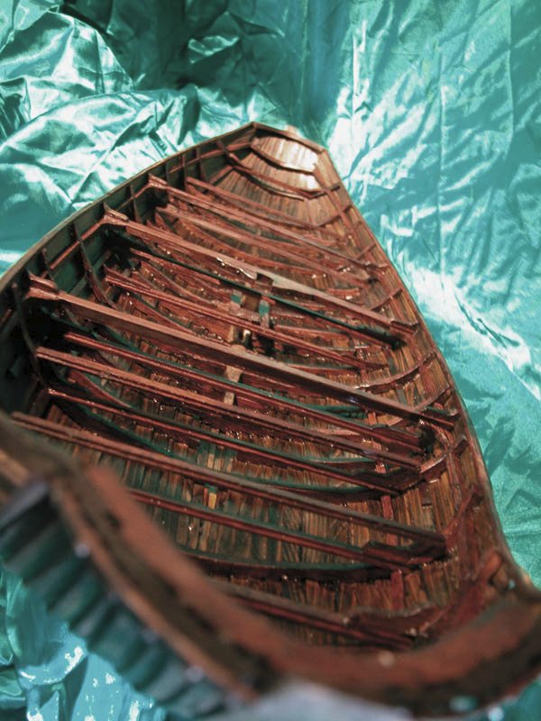
Yes, indeed, Steven. Following along the nordic theme. Here is the central part of the varmint framed loosely based on Skuldelev 1. The framing is providing some much needed stiffening to the hull but I suspect that the hull would have "worked' a fair bit in a heavy sea. Note that three of the beams are through beams. These through beams are seen on many of the hulc seals.

Cheers
Dick
- oneslim, popash42, BLACK VIKING and 6 others
-
9
-
On 3/20/2021 at 7:34 AM, Louie da fly said:
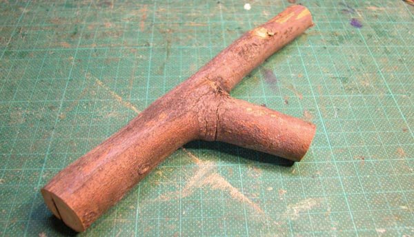
What kind of wood is that? It looks like it might be off a fruit tree.
I don't know. There are no fruit trees in the park but a range of native australian trees. The canine collector did not tell me from which tree it derived.
Dick and Maggie🐕
-
-
I haven't neglected the hulc, folks. Here are the steps in the making of the Skuldelev-like mast-step/keelson using a piece of local hardwood from the park. The pattern in the wood is easy on the eyes.
Cheers
Dick
- druxey, bolin, GrandpaPhil and 9 others
-
12
-
4 hours ago, Louie da fly said:
All us sandgropers had woggles
Didn't know you were a sandgroper ( a fond term for native-born west australians).
Yes Chuck, I will make stocks as well as 4 more anchors which will be tied down on the stocks on the foredeck, ready for use.
Dick
- mtaylor and Chuck Seiler
-
2
-
-
Thanks John , Steven and Schrader. Most kind.
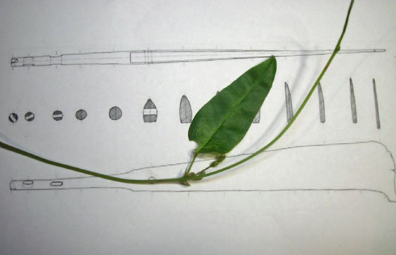
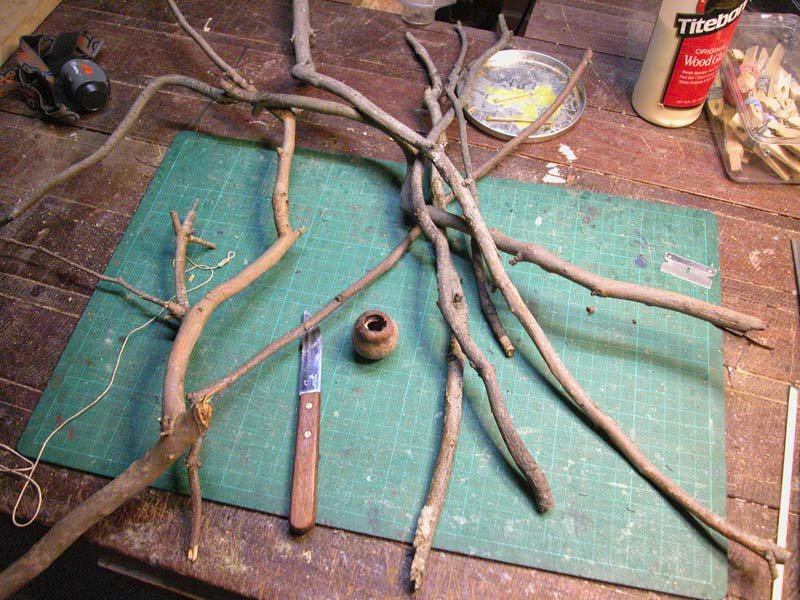
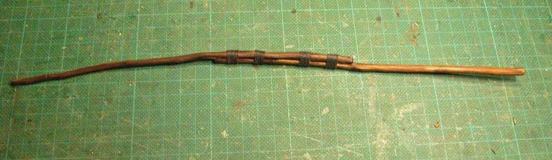
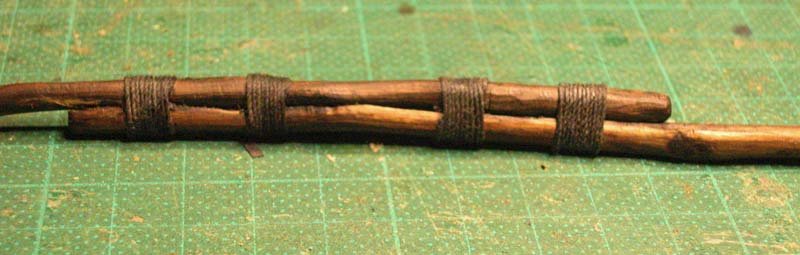
I have made the lateen yard using timber found in the local park. I was inspired by photographs of dhows which show that yards were not perfect machine turned bits of wood but somewhat rough and irregular. I suspect this was the case for this boat.

cheerio
Dick
- GrandpaPhil, Archi, vaddoc and 8 others
-
11
-
Here is the first anchor. Based on the anchor found in the 7th century YassiAda wreck
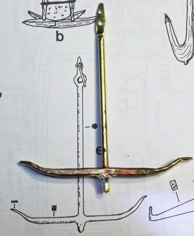
and after blackening
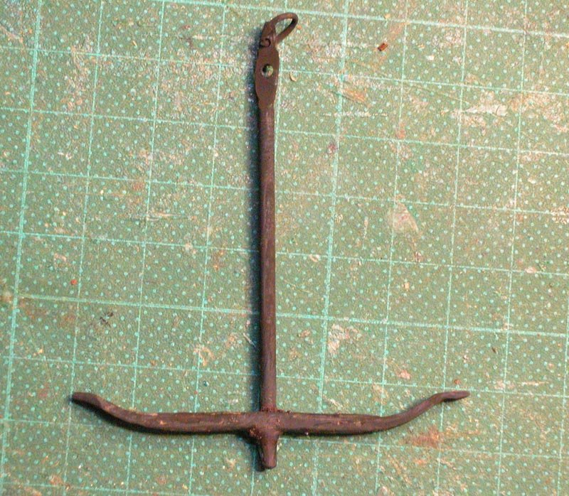
Cheers
Dick
-
On 2/12/2021 at 10:46 PM, woodrat said:
I have decided to avoid sheaved pulleys.
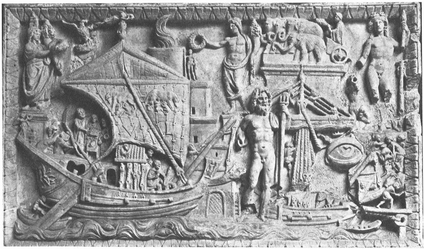
As justification for this , a bas relief from Portus Augusti in Ostia second century CE. Which indicates sheaveless pulleys on the forestay and hearts on the shrouds. Note the scuppers beneath each shroud with a rope suggesting that the shroud was looped through the scupper. I have included this on Yenikapi 12 model.

The Elusive Hulc by woodrat - FINISHED - 1:32 - plank-on-frame - a speculative reconstruction of a mediaeval merchantman
in - Subjects built Up to and including 1500 AD
Posted
Cometh the Banana Boat.
Thanks Steven and I look forward to your "nef"
Dick