
Supplies of the Ship Modeler's Handbook are running out. Get your copy NOW before they are gone! Click on photo to order.
×


Fam
-
Posts
185 -
Joined
-
Last visited
Reputation Activity
-

 Fam got a reaction from Obormotov in HMS Victory by guraus - scale 1:48 - plank on frame
Alexandru
I don't like looking as a parasite, but I'm all the time waiting for your updates for sucking the sap of shipbuilding from a master builder!
And once again my vampire-like thirst has been satisfied I've just learned an easy and effective method to install the bowsprit-deck gratings: thank you so much!!!
Fam
-

 Fam got a reaction from muratx in Le Colibri 1808 by Fam - scale 1:48 - POB French brick de 24
February 1st, 2016
Hi all
here I am with a new small update for my French Brig “Le Colibri”. It was a busy 2 weeks period, as the stern windows are very time consuming due to their very small size... but let’s start with order.
The first job I started with was the finishing of the transom. It consisted of two phases, the planking and the application of 4 moldings.
For the planking I used the same 0.5mm Tanganika veneer as for the main hull. In this case the planks layout is clearly depicted in the Ancre monography, so I quickly copied the plans and pasted the templates to the veneer.
Before gluing the planks I had to draw the horseshoe profile in the uppermost part of the transom face, and the profile for the large molding in its lower part. Then the planks application started.
After planking, the two round gunports where cut out and filed flush to their lining.
I then installed the first of the two moldings delimiting the area where some decorations are scheduled: this is built with a 2x1mm Pearwood strip bent with water and heat. The strip is sitting on the planks thickness, which greatly helps both shaping and gluing.
2mm width is much more than the amount required, as the molding only needs to be raised less than 1mm from the planked surface of the transom: it will be trimmed later.
Second phase, I added another Pearwood strip to the rearmost upper edge of the transom. This is 3mm wide, as the extra 1mm is needed to glue the molding above the transom: this way, this will also be the aft molding for the transom upper border that will contain some other decorations.
And finally a third 1x1mm strip is glued to the forward-most edge of the transom upper border, thus enclosing the second recessed area for the stern decorations.
As already said all these strips have excess of material: after glue was set, they were sanded with a rotating abrasive disk down to the required width and thickness.
BTW, I will never stop being amazed by the ease of bending this wood with just some heat, it’s unbelievable! Consider that I had to bend them in horseshoe shape and then edgewise to match the transom profile when seen from above, all in a single piece!!
Second task: the galleries.
Well, some of their parts are already visible in the above pictures, because I worked in parallel on multiple items while waiting for the glue to set. This was the sequence:
The profile of the side galleries, or fake windows as you prefer, is given in the plans. So again I just copied, mirrored and pasted it to both sides to draw the involved profiles.
With them defined, I could remove with a scalpel the portions of the three side moldings affected by the galleries:
Next I draw from the plans the floor and ceiling profiles for the windows area and transferred them to a thin plywood sheet: 2mm thick for the floor where a wide decorative molding is scheduled, 1mm thick for the ceiling where the molding is narrower.
Vertical positioning of the two profiles was quite tricky, as I had to match their slope (when seen from the side), the matcing surface of the transom wings, the large side molding of the hull and the multiple sheaves block.
In the end I realized that the only way to get the correct orientation was to fit the floor profile below the transom wings, and not just forward of them. So in the above picture the port floor profile is correctly shown in its final position, while the following picture shows the starboard side with the incorrect positioning. The starboard profiles were only temporarily glued, so I easily managed to remove both of them, rebuild a longer floor profile and reinstall them.
As far as the ceiling profile, its rear side is too high and touches the sheaves block with its internal corner: I had to lower it about 1mm at the rear to get the correct slope (seen from the side) and to clear the block with the required distance.
Windows then: a real pain in the ...! They are so small and tiny that I found no alternative other than building them one by one by hands: no automatization was possible, nor it was worth, because they are not equal to each other and they are just six.
So I cut very thin strips for the contour and the internal frame, using two qualities of Pearwood: 0.8mm thick darker Pearwood for the borders, 0.5mm light Pearwood for the frame pieces. Width (i.e. the window thickness) is 2mm for both and is reduced to 1mm after mounting is completed.
This is the first prototype almost completed: it took a whole building session of three hours to get at this stage!!
And this is the completed prototype, thinned and sanded, compared to the plans: measures are something about 12x7mm, with backward sloping tenon junctions at all corners.
I was satisfied with the result, so started with ‘mass’ production. The pillars are 2.7mm wide, and I chose a slightly different decoration with respect to the plans that, I remind, deal with the Le Cygne brig.
Another consideration about the general layout of the stern galleries: in all the plans of the Le Cygne class brigs we managed to find (with ‘we’ I’m meaning JA and myself), there are apparently only two layouts that only differ in the shape of the upper roof. The brig Le Cyclope, which pictures were posted by JA in his buildlog here (http://modelshipworld.com/index.php/topic/7795-hms-guadeloupe-ex-french-le-nisus-brick-de-24-by-jackaubrey-148-scale/?p=242287), shows the second possible layout.
Given the total absence of any drawing (so far) for Le Colibri, I decided to stick with the plans.
The following is another picture of the starboard gallery at a later stage: the glass, or blind, of the fake windows is simulated by gluing a piece of clear plastic sheet to the back of the window structure. I sanded the front surface of the plastic with very fine (1000 grade) sanding paper to diminish its glossy look, ant then painted black its back side.
The port windows and pillars completed: a simple capital is still missing from both ends of the pillars, but the basic shape is complete.
Now the upper roof: I took advantage of the skill learned while making the bow cheeks, because even in this case it was just a matter of matching multiple surfaces.
This is the starting point, with a block of Basswood cut and sanded to match the hull (on the internal side) and the front face of the transom wing (on the back face).
Then the external profile is vertically cut just matching the border of the windows ceiling profile. Also the forward slope is roughly cut, using the profile line draught on the hull side:
Next the forward slope is refined, until getting the correct shape, and the upper face is cut following the line draught on the hull:
Finally the inside part is cut, removing the material blocking the sheaves block:
And this is the roof piece sanded smooth, sealed, sanded again and painted matt black:
Note that also the recessed area for the transom border decoration has been painted, in preparation for the next stage.
The final look of the port gallery, with the required decorative moldings applied to the roof. A floral decoration is still needed on the roof surface; I have to figure out how to build one sufficiently thin and delicate for my taste. A paper template for the transom border decoration is also evident.
As all these jobs were quite demanding, I needed something alternative to relax. So switched back to the bow area and started preparing the pieces for the catheads.
First step was to cut the recesses in the gunwales that are needed to house the cathead beam.
I prepared a template showing the beams angle as seen from above, and positioned it on the hull centerline and, in the longitudinal axis, using the only reference body that I have already available: the bitt for the bowsprit foot.
After cutting the two recesses in the gunwales, I could start with the inner beam: Cherrywood was the choice this time, to match the color I’ve decided for all the deck fittings. I started removing a portion of molding and then shaped the face matching the inside bulwark and the waterway. My scope was to get a tight fit without cutting the waterway, so took my time and adapted the lower surface with continuous test fits and modifications.
For the outward side, I had to build a simple jib permitting to obtain the correct cathead angle in the horizontal and vertical plane. The vertical knee is just a dummy for the final knee, whose shape is available in the Ancre plans. The horizontal knee is just a piece of wood cut to the correct angle, with respect to the outboard surface of the bulwark, and resting under the protruding gunwale. To obtain the correct horizontal angle, i.e. with the cathead slightly backward of the perpendicular to the bulwark, I used again the template above shown.
Also visible is the upper portion of the inner vertical beam, that I left longer than needed.
Last picture related to the cathead shows the completed starboard item. To reach this stage I deepened and sloped the gunwale recess and cut the internal beam flush with the recess, so that the athwart beam could be positioned with the correct angles. Then glued the two beams together, strengthening the joint with a brass pin that will remain invisible. Then completed the job with filing and sanding until getting the final shape.
Were the catheads of this type built in a single piece, or by joining two beams the way I did? And in the latter case, was any metalwork visible for the junction of the two pieces? I don’t know, I’ve seen examples of both types... any suggestion?
Last job I did, again to ‘relax’ among more demanding works, was to start carving the transom decorations.
I evaluated different types of decoration suitable to fill the narrow strip on the transom border, and even considering that the same decoration would have to be used for the slightly larger area on the back face of the transom. I considered simple disks, shells, leaves, had a look in my photographic database of shipmodels...then decided for a sequence of overlapping stylized leaves: leaves and flowers should match the typical environment where hummingbirds (= colibri) live, it looked like a good and logic choice.
This is the start of the task, from a 3.2x1mm strip of dark Pearwood. The pencil gives an idea of proportions.
The shown rotary tools are my best friends for this type of carvings: I got them from my dentist, as a present after hours of pain and thousands of Euros
The two missing tools in above picture are a very sharp cutter blade and a chisel I build from a screwdriver... less than 1mm wide, good handle, very hard steel that keeps quite well the cutting edge.
The next picture shows the first strip completed and the next ready to start. The completed decoration has been already bent in two directions and twisted to conform the composite shape of the transom border: the carving makes its easier, together with water soak and heat, but Pearwood is just...
And this final picture shows the starboard gallery as it was yesterday evening
Regards
Fam
-
 Fam got a reaction from Archi in A question on working mizzen lateen sails
Hi all
may I show you this:
Hope this helps.
Ciao
Fam
-
 Fam got a reaction from KORTES in Le Colibri 1808 by Fam - scale 1:48 - POB French brick de 24
April 8th, 2016
Hi all
another quick update about the head-timber works.
The third couple of timbers is installed and the lower rail is being test-fitted in the next picture. Note that I had to complete the finish of the three head-timbers in their outer face, for the portion between the upper cheek and the rail, because the latter will obstruct the accessibility to this area for finishing. Therefore I glued a narrow strip of paper, blackened with a felt pen, inside the scraped molding and then re-touched with black acrylic paint to match the bow finish.
Here, in the two following shots, the two lower rails are completed and definitely installed. They are monolithic, i.e. built in a single piece, because their size and curvature are smaller and I thought they could be obtained from a single piece of wood.
Matching the rail with the three existing head-timbers, with the bow (between the hawse holes) and with the main rail was another “pleasant” task
And finally the fourth head-timber is completed and installed: it sits on top of the lower rail (where it touches the bow surface) and is connected to the main rail. All timbers are finished with the black strip on their outer face.
Forward platform
After completing the lower part of the ship’s head, I have switched to its upper side ... what I call “bowsprit deck” or “forward platform” (pretty sure the name is another, but I don’t know the correct English term).
Several cross timbers are laid in athwart direction connecting the two main head-rails. They are longitudinally positioned close to the head-timbers above described, but not precisely overlaid: there is a small shift forward and aft of the two forward-most timbers, to leave space for the bowsprit gammoning.
The timbers are intended to support a series of fore-and-aft smaller timbers (or “ledges”?), thus creating a sort of grating, or something that reproduces the carlings-ledges structure of the decks but with the scope of a grating.
Connection among the “ledges” parts and the athwart supports should be done with a series of recesses (notches) 1mm wide and 0.9mm spaced apart to each other, like visible on the wedge piece at the head-of-the-knee that I’ve already fixed.
The more proper way of doing this job is probably drawing reference longitudinal lines across the athwart beams and then cutting the teeth, with a sharp chisel or cutter, on their fore and aft upper edges. I thought that this method leaves large space for alignment imprecisions, any error in cutting the recesses would reflect in a deviation of the ledges from the F&A direction and from their parallelism. So decided for simulating this method by using instead the method shown here on MSW by Alexandru (Guraus’s buildlog of HMS Victory).
I built a step on the fore and aft upper edges of the athwart beams by overlaying two pieces: the lower is 3mm wide by 2mm thick, the upper batten is 2mm wide by 1mm thick: the resulting beam is a 3x3mm timber with two continuous 0.5x1mm steps along the upper edges, which will house the ledges timbers. In this way I will be able to take care of their correct alignment and spacing to each other.
The following picture shows the first two cross-beams installed: the steps are visible on the fore edges. Choice of material for the entire forward platform is a lighter shade of Pearwood (Swiss pearwood from CrownTimberyard company, great stuff!!), contrasting with the darker shade of the lower structures.
Once again, I couldn’t be happier of my decision to buy a disk sander (Proxxon TSG250/E in my case): once the proper angles needed to match the rails with the beams are found, with some trials, then obtaining the correct fitting for all the cross-beam timbers with the disk-sander is easy and fast, just a matter of few seconds! No need to say I strongly recommend this tool.
Here below the third, and last, cross-beam is positioned: it is longitudinally positioned so that it interferes with the stem, that seemed a bit weird to me. But after checking and measuring on the plans and verifying on the model, and then double-checking and measuring again, I got to the conclusion that its position is correct … or better it is compliant with the plans (supposing they are correct).
The problem with this position is that the beam, apart from crossing the stem, is not able to support the longitudinal grating. So I added another small piece just forward of the stem and connecting the two parts of the beam: probably not the correct solution, but I could not imagine another way out from this impasse. The building method for this cross-beam was the same, simply divided in two parts.
The first 5 longitudinal parts of the gratings (ledges) are also installed, to demonstrate the concept. They seem to be slightly not parallel, but it is just an impression from the picture: I ensure they are parallel!
And here again the forward platform at a later stage, with more ledges installed and two of the knees connecting the beams to the rails installed:
The knees are notched to match the beam step, then I will cut the recesses for the ledges in the after edge of each knee.
Finally a shot from the opposite side of the ship: the stern transom is finished in matt black and the moldings and decorations pop-out much more evident. I like very much the way light reflects on the Pearwood leaf decorations, giving them different shades of color that are only due to different orientation of the leaves.
Painting of the counter down to the second molding is not yet complete.
That’s all for today.
Best regards
Fam
-
 Fam got a reaction from Siegfried in Le Colibri 1808 by Fam - scale 1:48 - POB French brick de 24
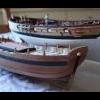
For those who don't have access to the German forum where Johann is posting his work, I show here three steps describing what I'm trying to obtain (Johann if this is disturbing just let me know and I'll remove the images immediately):
- cast support parts for carronade barrel
- unassembled parts
- the completed carronade
All his pieces are brass, either lathed or cast. I was not so lucky, so all my parts will be cast in pewter. The final finish will be in gun-metal paint, polished with some lead pencil dust to improve the metallic look. The 9pdr long gun pictures I posted some time ago show what I mean.
I'd like to highlight that the design of my barrels seem to be exactly the same of Johann's, but I only referred to Ancre plans: probably the weapon was the same type for both ships, regardless of the different years of building.
Also note how the lower part of the carriage has no wheels, and carronade training is done by rotating the upper sledge ... this seems to be a little bit weird, but I don't have the knowledge to contest this layout.
Cheers
Fam
-
Fam got a reaction from Siegfried in Le Colibri 1808 by Fam - scale 1:48 - POB French brick de 24
February 23rd, 2016
Hi all
as I’m working on multiple items, I’ll post several small updates in the next weeks.
Firstly I’d like to show the pieces that complete the stern galleries in their bottom part: they were carved from solid blocks of Basswood, using a technique similar to the cheeks for matching the curved surface of the hull. Of course I started from the flat upper surface, then slowly carved the internal surface until getting a good fit with the curved hull. With these two joints completed, I traced the lateral and vertical profiles of the piece (as seen from above and from the side) and cut them with the scroll saw. Then I had to find a good match with the counter, adapting a little bit the shape of the back face so that the counter is flush with it. Finally I could carve the external surface so that, when seen from behind the poop, it is a continuation of the transom profile (third picture).
The above picture also shows a little molding added to the lower edge of the counter, where it joins the hull planking. Another molding covers, and completes, the structure (floor) below the fake windows. Its junction with the lower transom molding will be later covered by a small carving (see below).
A little touch of personalization is the ribbon with the ship’s name, that I’ve scheduled to carve from dark Pearwood (as for all the transom decorations). Of course I’ve no historical reference at all about this detail, so decided for something sufficiently simple and not intrusive but at the same time clearly identifying the ship.
Speaking of decorations ... I was inspired by Ed Tosti buildlog of the Young America clipper, where he describes the stern friezes ... so decided to give it a try when I saw some FIMO© packages in a fine arts store.
I chose two colors because wanted to try obtaining a tone as much similar as possible to the shade of Pearwood I’m using for the stern decorations.
To the right of the FIMO© is a test decoration (branch with leaves) that I obtained with 8 parts of light-tan color and two parts of cherry color ... here below is how the 8:2 mix is matching the two shades of Pearwood I’m currently using (the lower is the discarded cathead piece) ...
... and here is how the same sample looks like on the starboard galleries:
After sculpting the sample on a flat pane of glass, I cooked it (still on the glass) for 30 minutes in the kitchen oven pre-heated at 110°C: no change in color to report, but the material is still a bit flexible. This is ok for me, considering that the decoration will be applied to curved surfaces. I’ve to admit I’m quite surprised by how easily I got it and pleased by the result.
Next will be to mold the floral decorations for the upper and lower pieces of the galleries, because that little carving you can see at the rear-lower corner of the galleries (above picture, at the junction between two moldings I mentioned above) took three hours of total concentration and sweet and stress... I cannot really imagine carving all the remaining decorations! My total admiration and respect for those who have this skill, but it is not my job ... definitely!
Jumping to another matter: there are several little details on the exterior of the bulwarks that I’m keeping to relax from the stress of carving :
- the oar ports shutters
- the rails for the carronades breeching ropes
- the external ladder steps
The shutters have no history: they are those simple flat pieces, with rain-drop shape, that I’ve already showed when I was deciding which shape to use for the oar ports. I just copied and pasted their paper drawings on a 8mm strip of Yellowheart wood, 1.5mm thick, then cut them out with the scroll-saw, sanded, hand-milled the step in their edge and glued to the hull. The brass pivot nail will come later.
They are visible in the latter pictures of today’s post. Two out of seven on each side are left opened, so the oar port shape is partially visible; the others are closed.
About the breeching ropes rails, they are basically 2.2x3mm battens with a U channel milled in the narrower side. I’ll show their scope in a while...
The problem with these pieces is that I don’t own a mill, even if that beautiful Proxxon MF70 machine has been in my wish list for so long time that I’m starting to think I will never give this present to myself!
So I had to try a setup of my column drill to make it work as a mill, using a 1mm diameter spherical mill bitt. I spent an entire Saturday afternoon trying to get a good and stable setup, with no result (well, I don’t consider 6 milled pieces thrown in the trash bin as a usable result!). The following Sunday I tried again with a different setup, and finally succeeded!
The following picture shows my less than amateurial setup while milling one Yellowheart strip, the next picture shows the completed job.
This is how this detail works: the carronade breeching rope of Le Cygne is not attached with hooks, or ringbolts, to the inside of the bulwark. It is made by a continuous rope loop, which starts inboard on one side of the carronade, passes outboard through a hole in the bulwark, around the external rail, back inboard through another bulwark hole on the opposite side, around the carronade, through the breech rope ring in the back of the barrel and then back to the starting point where it is fastened with a double seizing (see red arrow in the next shot).
The external rail piece is obtained, after the U channel is milled, by drilling two holes in the channel at 23mm distance and then cutting the batten at the far side of these holes. Then the rail profile is drawn on the batten wider side and the rounded shape is sanded with the disk sander.
The rail is glued to the bulwark, below the gunport sills, after having drilled the two pass-through holes in the bulwark itself (drilling jig in the next picture). Well ... only partially drilled, because these holes are sloping upward to exit above the waterway, so their remaining portion will be drilled from inside to outside.
Final look of the rail (also the oar-ports shutters are visible):
This is just the first test piece; the next 13 will come in the following days.
Nothing to say about the ladder steps, will be done in the next days. Stay tuned...
Cheers
Fam
-
Fam got a reaction from Siegfried in Le Colibri 1808 by Fam - scale 1:48 - POB French brick de 24
February 1st, 2016
Hi all
here I am with a new small update for my French Brig “Le Colibri”. It was a busy 2 weeks period, as the stern windows are very time consuming due to their very small size... but let’s start with order.
The first job I started with was the finishing of the transom. It consisted of two phases, the planking and the application of 4 moldings.
For the planking I used the same 0.5mm Tanganika veneer as for the main hull. In this case the planks layout is clearly depicted in the Ancre monography, so I quickly copied the plans and pasted the templates to the veneer.
Before gluing the planks I had to draw the horseshoe profile in the uppermost part of the transom face, and the profile for the large molding in its lower part. Then the planks application started.
After planking, the two round gunports where cut out and filed flush to their lining.
I then installed the first of the two moldings delimiting the area where some decorations are scheduled: this is built with a 2x1mm Pearwood strip bent with water and heat. The strip is sitting on the planks thickness, which greatly helps both shaping and gluing.
2mm width is much more than the amount required, as the molding only needs to be raised less than 1mm from the planked surface of the transom: it will be trimmed later.
Second phase, I added another Pearwood strip to the rearmost upper edge of the transom. This is 3mm wide, as the extra 1mm is needed to glue the molding above the transom: this way, this will also be the aft molding for the transom upper border that will contain some other decorations.
And finally a third 1x1mm strip is glued to the forward-most edge of the transom upper border, thus enclosing the second recessed area for the stern decorations.
As already said all these strips have excess of material: after glue was set, they were sanded with a rotating abrasive disk down to the required width and thickness.
BTW, I will never stop being amazed by the ease of bending this wood with just some heat, it’s unbelievable! Consider that I had to bend them in horseshoe shape and then edgewise to match the transom profile when seen from above, all in a single piece!!
Second task: the galleries.
Well, some of their parts are already visible in the above pictures, because I worked in parallel on multiple items while waiting for the glue to set. This was the sequence:
The profile of the side galleries, or fake windows as you prefer, is given in the plans. So again I just copied, mirrored and pasted it to both sides to draw the involved profiles.
With them defined, I could remove with a scalpel the portions of the three side moldings affected by the galleries:
Next I draw from the plans the floor and ceiling profiles for the windows area and transferred them to a thin plywood sheet: 2mm thick for the floor where a wide decorative molding is scheduled, 1mm thick for the ceiling where the molding is narrower.
Vertical positioning of the two profiles was quite tricky, as I had to match their slope (when seen from the side), the matcing surface of the transom wings, the large side molding of the hull and the multiple sheaves block.
In the end I realized that the only way to get the correct orientation was to fit the floor profile below the transom wings, and not just forward of them. So in the above picture the port floor profile is correctly shown in its final position, while the following picture shows the starboard side with the incorrect positioning. The starboard profiles were only temporarily glued, so I easily managed to remove both of them, rebuild a longer floor profile and reinstall them.
As far as the ceiling profile, its rear side is too high and touches the sheaves block with its internal corner: I had to lower it about 1mm at the rear to get the correct slope (seen from the side) and to clear the block with the required distance.
Windows then: a real pain in the ...! They are so small and tiny that I found no alternative other than building them one by one by hands: no automatization was possible, nor it was worth, because they are not equal to each other and they are just six.
So I cut very thin strips for the contour and the internal frame, using two qualities of Pearwood: 0.8mm thick darker Pearwood for the borders, 0.5mm light Pearwood for the frame pieces. Width (i.e. the window thickness) is 2mm for both and is reduced to 1mm after mounting is completed.
This is the first prototype almost completed: it took a whole building session of three hours to get at this stage!!
And this is the completed prototype, thinned and sanded, compared to the plans: measures are something about 12x7mm, with backward sloping tenon junctions at all corners.
I was satisfied with the result, so started with ‘mass’ production. The pillars are 2.7mm wide, and I chose a slightly different decoration with respect to the plans that, I remind, deal with the Le Cygne brig.
Another consideration about the general layout of the stern galleries: in all the plans of the Le Cygne class brigs we managed to find (with ‘we’ I’m meaning JA and myself), there are apparently only two layouts that only differ in the shape of the upper roof. The brig Le Cyclope, which pictures were posted by JA in his buildlog here (http://modelshipworld.com/index.php/topic/7795-hms-guadeloupe-ex-french-le-nisus-brick-de-24-by-jackaubrey-148-scale/?p=242287), shows the second possible layout.
Given the total absence of any drawing (so far) for Le Colibri, I decided to stick with the plans.
The following is another picture of the starboard gallery at a later stage: the glass, or blind, of the fake windows is simulated by gluing a piece of clear plastic sheet to the back of the window structure. I sanded the front surface of the plastic with very fine (1000 grade) sanding paper to diminish its glossy look, ant then painted black its back side.
The port windows and pillars completed: a simple capital is still missing from both ends of the pillars, but the basic shape is complete.
Now the upper roof: I took advantage of the skill learned while making the bow cheeks, because even in this case it was just a matter of matching multiple surfaces.
This is the starting point, with a block of Basswood cut and sanded to match the hull (on the internal side) and the front face of the transom wing (on the back face).
Then the external profile is vertically cut just matching the border of the windows ceiling profile. Also the forward slope is roughly cut, using the profile line draught on the hull side:
Next the forward slope is refined, until getting the correct shape, and the upper face is cut following the line draught on the hull:
Finally the inside part is cut, removing the material blocking the sheaves block:
And this is the roof piece sanded smooth, sealed, sanded again and painted matt black:
Note that also the recessed area for the transom border decoration has been painted, in preparation for the next stage.
The final look of the port gallery, with the required decorative moldings applied to the roof. A floral decoration is still needed on the roof surface; I have to figure out how to build one sufficiently thin and delicate for my taste. A paper template for the transom border decoration is also evident.
As all these jobs were quite demanding, I needed something alternative to relax. So switched back to the bow area and started preparing the pieces for the catheads.
First step was to cut the recesses in the gunwales that are needed to house the cathead beam.
I prepared a template showing the beams angle as seen from above, and positioned it on the hull centerline and, in the longitudinal axis, using the only reference body that I have already available: the bitt for the bowsprit foot.
After cutting the two recesses in the gunwales, I could start with the inner beam: Cherrywood was the choice this time, to match the color I’ve decided for all the deck fittings. I started removing a portion of molding and then shaped the face matching the inside bulwark and the waterway. My scope was to get a tight fit without cutting the waterway, so took my time and adapted the lower surface with continuous test fits and modifications.
For the outward side, I had to build a simple jib permitting to obtain the correct cathead angle in the horizontal and vertical plane. The vertical knee is just a dummy for the final knee, whose shape is available in the Ancre plans. The horizontal knee is just a piece of wood cut to the correct angle, with respect to the outboard surface of the bulwark, and resting under the protruding gunwale. To obtain the correct horizontal angle, i.e. with the cathead slightly backward of the perpendicular to the bulwark, I used again the template above shown.
Also visible is the upper portion of the inner vertical beam, that I left longer than needed.
Last picture related to the cathead shows the completed starboard item. To reach this stage I deepened and sloped the gunwale recess and cut the internal beam flush with the recess, so that the athwart beam could be positioned with the correct angles. Then glued the two beams together, strengthening the joint with a brass pin that will remain invisible. Then completed the job with filing and sanding until getting the final shape.
Were the catheads of this type built in a single piece, or by joining two beams the way I did? And in the latter case, was any metalwork visible for the junction of the two pieces? I don’t know, I’ve seen examples of both types... any suggestion?
Last job I did, again to ‘relax’ among more demanding works, was to start carving the transom decorations.
I evaluated different types of decoration suitable to fill the narrow strip on the transom border, and even considering that the same decoration would have to be used for the slightly larger area on the back face of the transom. I considered simple disks, shells, leaves, had a look in my photographic database of shipmodels...then decided for a sequence of overlapping stylized leaves: leaves and flowers should match the typical environment where hummingbirds (= colibri) live, it looked like a good and logic choice.
This is the start of the task, from a 3.2x1mm strip of dark Pearwood. The pencil gives an idea of proportions.
The shown rotary tools are my best friends for this type of carvings: I got them from my dentist, as a present after hours of pain and thousands of Euros
The two missing tools in above picture are a very sharp cutter blade and a chisel I build from a screwdriver... less than 1mm wide, good handle, very hard steel that keeps quite well the cutting edge.
The next picture shows the first strip completed and the next ready to start. The completed decoration has been already bent in two directions and twisted to conform the composite shape of the transom border: the carving makes its easier, together with water soak and heat, but Pearwood is just...
And this final picture shows the starboard gallery as it was yesterday evening
Regards
Fam
-
Fam got a reaction from Siegfried in Le Colibri 1808 by Fam - scale 1:48 - POB French brick de 24
December 24th, 2015
Hi all
as I promised, I’m able to show the completely coppered hull.
Firstly a couple of pictures at an earlier stage, when the plates covering the keel thickness are still missing.
I tried to adjust the color rendering so to match the real color of new copper, which is amazingly bright and shiny.
The following pictures show how I set the copper foil into the narrow and shallow groove that separates the keel from the false-keel... I don’t know if the picture manages to render the effect... well it is not exactly like if the copper continues between the two parts, but is looking almost as I wanted.
Next picture is how I prepared the stamp for the plates covering the keel width. The holes will house the steel needles used to stamp the simulated nails on the copper tape.
There is no detail about these plates in the Ancre monography, but I needed a greater width to have some margin for bending each plate to the sides of the keel timbers. The keel is 7mm thick, as I wrote above, and I managed to find a copper tape 12.7mm wide.
The layout of the nails is the same as for the other plates, just extended to the larger width of these plates. But, differently from the hull plates, I added another row of nails to the side edge, so that both left and right edges look correctly.
I imagined that the curvature of the bow timbers profile would have caused the plates to wrinkle at the sides of keel. To minimize this, I decided to reduce the plates length to about a half of the length of the hull plates: I firstly tried with 20mm length, but the wrinkles were still present and quite difficult to avoid. At 15mm length (instead of the standard 33mm) I managed to avoid the buildup of these wrinkles. So the final size I chose is 12.7mm width and 15mm length.
As for the hull plates, I started producing a small batch of plates for testing how they looked. When I laid the new plates on the side of those I’ve used for the first test, my heart almost missed a beat... OMG, the color was very different!!! More pinkish, as you can see in the following picture:
Probably a different brand of copper, or a different surface finish, or whatever... I didn’t know what to think!
I stopped working for a couple of days, thinking at what to do to fix this problem. Then just tried: degreased both copper types with acetone (nail polisher), then rubbed them with very fine steel wool ... and the miracle happened!
I don’t know what the reason was, I cannot believe the older plates had already oxidized ... well I didn’t care: now both plates types showed the same color.
Ok, let’s go forward: the amount of wide plates was not much, just about 20. So it was a job quickly done.
The next two pictures show the final plates installed on bow timber and stern post... you can see that the colors are still different, I fixed it later.
The last step of coppering was to try reducing the excessive shining of new copper by applying a weathering patina, so to simulate the natural ageing of copper.
I used the recipe suggested by Dirk (Dubz), a mixture of vinegar and salt, with as much salt as can be added to the solution before it starts to fall to the bottom of the pot. I also heated the vinegar to melt a bit more salt... a super-saturated solution I think it’s called.
Again, I used the tester plates to check the effect:
What above picture is showing is much more than the real effect, but I wanted to show it because three different areas are visible: to the left is the original copper, in the middle is the copper just covered with some mixture and to the right is the copper after the mixture has dried.
To be honest, I saw this result on the hull before, then I checked on the testers and noticed that a white patina had developed... in other words I was impatient to test the new technique and did not left enough time to the chemicals to complete their effects.
The effect of the mixture was treble: immediately the copper changed color, taking a more brownish tone. Then it lost great part of its shine. And finally the white patina appeared, probably a side effect of the excess of salt in the mixture...
Back to the hull: before applying the mixture I thoroughly degreased the entire hull with acetone, then passed all the plates with very fine steel wool... and the copper colors harmonized.
Then applied the mixture in several coats, using a ragged piece of fabric that I dipped into the solution: in this way I tried to avoid leaving any excessive amount of the stuff on the copper.
And this is the final effect:
I’m now thinking at how to face this patina, even though I admit that I’m not disliking the final look ...
A couple more shots of the coppered hull how as it is right now, before the shipyard was closed for Christmas holidays.
I used a different camera, with much lower performance, and this is the reason for such different color rendering...
You may see that I also added a third molding strip just below the water scuppers, an addition of the very last minutes. I’ve missed it during all my previous analysis of the plans, but discovered it when checking for the next job.
I’ve used Yellowheart wood strips that I had available in the scrap parts box: don’t be surprised for the strange color matching, because all this area will be painted black.
To set these strips I temporarily glued several 4.5mm wide spacers below the main molding (they are visible in the above picture), then used them as a guide for laying the new molding.
Next job, in the first days of the New Year 2016, will be the cheeks that laterally support the knee-of-the-head ... stay tuned!
I wish you Merry Christmas and a Happy and Prosperous New Year 2016
Fam
-
Fam got a reaction from Siegfried in Le Colibri 1808 by Fam - scale 1:48 - POB French brick de 24
November 30th, 2015
… Continuation …
Gunwales
Next scheduled step was building the gunwales, as they complete the upper edge of the bulwarks, protect them and give also more strength, that is not bad considering the hull will be inverted for some time.
The method is the same already described by my good friend JA, but I will show some more details about the procedure.
First step is to draw the profile of the gunwales: I used a piece of scrap cardboard (Corn Flakes boxes ), laid it flat above the bulwarks and transferred the bulwarks profile to the underneath of the cardboard with a sharp pencil.
The gunwales total width can be measured on the plans, which also show how they protrude about 1.5mm inside and outside the bulwarks. So I had to add another “parallel” line externally to the one already drawn, spaced 1.5mm away, and a second one internally to the existing line, at the correct distance to obtain the total width.
The above is the final result, with several red lines also traced: the midship line (to check symmetry) and the lines showing how to split the gunwales in several pieces.
I wanted to simulate the use of wood boards about 7-8m long, joined with scarph joints. So added these lines, drew the joints and cut the resulting pieces:
Then glued these pieces to a 2mm thick Pearwood board and cut them out with a scroll-saw.
Starting from the transom, I positioned the gunwale pieces on top of the bulwarks, alternating port and starboard sides to increase the visibility of any asymmetry. The pieces were held in position by pins inserted in the toptimbers and gunport side-lining pieces:
Piece after piece after piece...I got to the bow optimizing the flow of boards and every joint.
The gunwale boards have a composite profile on their internal and external edges, so I used the experienced technique of scrapers by cutting the required profile in a steel blade. Then locked every gunwale piece in a vise and scraped the two sides…
...with this result:
To avoid any painting problem after the installation, I pre-stained the boards underside with black stain. Here are all the gunwales pieces:
And finally the installation started. Here the problem was to firmly hold each piece pressed against the top of bulwarks, so to obtain a strong glued joint. The pin holes provided the needed reference for the alignment.
Above is the final results completed and below the gunwales finished with black acrylic paint: two light coats, a light sanding, a third light coat as final finishing:
The preparation for coppering was then concluded by painting a black area just few millimeters wide upward of the waterline: I wanted to avoid having the need to paint the hull down to the copper, and also wanted to avoid the need to protect the copper from overpainting, so prepared the base well in advance.
The waterline is still visible below this painted area because it will be the reference for laying the first row of plates.
And finally… coppering!!
I protected the gunwales and inverted the hull. After a long exchange of PMs with Archjofo/Johannes (thank you very much, you were very kind!) I obtained several pictures of the hull of his Le Crèole corvette, which is coppered exactly the same way described in the monography of Le Cygnus brig (ref. above posts).
The only difference is a single line of narrow copper plates at the waterline instead of four lines.
So I started producing the plates for the waterline: they are as long as the main plates, 33mm corresponding to 1.60m in the real world, but only 5.5mm wide instead of 10mm (0.50m). The simulated nails heads are 0.6mm diameter, corresponding to about 30mm. They obviously have a different (mirrored) layout from port to starboard.
Laying of the plates starts at the rudder post timber and proceeds forward, with an overlay of the plates by about 1mm (41mm in the real world).
And I immediately had to face a problem… how to approximate a curved line with straight segments! The solution was probably to use curved plates, prepared ad-hoc by the master blacksmith of the shipyard.
I simply used the prepared plates and cut the upper profile round, following the waterline. The lower profile of the plates waterline row results in a split-line, but it will be covered by the following rows of copper.
The flow of the row at the bow is much easier:
And these are the first two rows of standard plates completed yesterday night, with the few plates I had already prepared... unfortunately I had to temporarily close the blacksmith workshop because my relatives loudly protested for the hammering noise
To find its correct shape (natura lcurvature line) I used a 10mm wide plank, placed on the hull and bent to naturally follow the curvature of the hull. The next rows are just following the upper profile of this first:
Next days will be busy with the coppering. I will have also to prepare a third stamp for the plates covering the thickness of the keel-sternpost-stem timbers.
Cheers
Fam
-
Fam got a reaction from Siegfried in Le Colibri 1808 by Fam - scale 1:48 - POB French brick de 24
November 24th, 2015
Hi all
while playing with the copper, at the same time I’m proceeding with the preparatory steps that I’ve described above.
Hawse holes and water scuppers lining
Both these jobs are now completed with the method I’ve described in the previous posts: in the end I didn’t try with the brass tubes because the result I’ve got with simple paper is fully satisfactory for me. Here are a couple of shots (still not painted):
Bowsprit housing
Every preparatory job has...a preparatory job to be completed before!
So before building and installing the gunwales, I had to clear the housing for the bowsprit mast in the bow portion of the bulwark... but before being ready to do this task, I had to build the large bitt housing the foot of the bowsprit (btw, what’s its name?).
I used Cherry wood for it, and just followed the drawings in the Ancre monography. I left the two legs longer than needed, then cut two square holes in the deck planks to house the legs. The holes are as deep as the deck planks thickness, so the bowsprit bitt is fixed directly to the false deck plywood.
The final height of the legs is then adjusted so to have the correct distance between the deck and the horizontal beams of the bitt. Then, after adding a couple of brass pins to the center of the bitt legs, the bitt was positioned into its location. No glue for now, but the fit is so tight that it is not really needed while I’m checking the bowsprit position. The next pic shows the bitt before shortening the legs.
To carve the bowsprit housing I firstly prepared a dummy of the mast, using a 10mm diameter dowel.
First step was to measure the slope of the mast from the plans, with respect to the deck surface, which is about 19.5 degrees. Then I cut three faces into the foot of the dummy: first was a sloped surface (1) to match the deck: the easier way to do this is to use the disk sander with the tilting table set to 19.5deg.
Then I had to sand the foot of the dowel at 19.5deg from the dowel section (2), so that it remains vertical w.r.t. the deck. Again, with the disk sander help...
Third I cut two flat and parallel surfaces on the sides of the bowsprit foot (3), so that its width is exactly the same as the distance between the bitt legs.
After these steps were done, I started cutting the bulwark above the bow timbers: initially with 10mm width, the same as the bowsprit diameter, then progressively narrower until obtaining a ‘U’ shape sloping inward. In the end, the external and internal pieces of the bow timbers were joined in a continuous saddle for the mast. While slowly removing material from the bulwark, the bitt provided a stable stop to the mast foot and at the same time a reference for its slope. A third check point was the distance between the dummy mast and the top of the bow timber, where the figurehead will be attached (sorry, don't know the correct name of this part):
9pdr guns
Continuing with the 9pdr guns, I verified that the carriage cheeks were about 1mm too narrow for the gun barrel ... actually, it is the opposite, because the carriage is perfectly matching the plans.
So, some deconstruction time also for me: I disassembled the cheeks from the axles and forward piece, built a new forward piece 1mm wider and reassembled the 5 pieces. The following picture shows the new wider carriage (left) compared to the original. The next shows how the second barrel (still bare) sits comfortably between the cheeks and is able to be trained upward without interference.
The following picture shows both the carriages rebuilt, with all the bolts and ringbolts required and with the wheels completed by their iron bands. Next is a shot showing the two barrels painted: the first still with matt finish, the farther also polished with a nylon rotative brush and with some graphite powder from a 2B lead pencil.
Final steps were to build the brass strips fixing the barrel trunnions to the carriage. They are cut from brass 0.5mm thick sheet, bent to match the trunnion, drilled with two holes and fixed by a 0.5mm brass hook (to the rear) and a 0.8mm pin (to the front).
Finally, several shots showing the completed guns on the deck, occupying their position at the first gunports. The barrel is now correctly aiming upward, even though the elevation quoin is still not in its final position.
The above closer picture shows the elevation quoin, with the pin handle lathed from a Birch toothpick, and the brass pins through the wheels axles. All the metal parts have been chemically blackened.
Finally, I also tried to position the guns at the stern chase gunports ... again satisfactory !!
To be continued...
Fam
-
Fam got a reaction from Siegfried in Le Colibri 1808 by Fam - scale 1:48 - POB French brick de 24
November 10th, 2015
Hi all
the first steps forward in the above scheduling, plus some extras...
I decided to draw the waterline as first step, as the following coats of sealer would have protected the WL from the following sandings. This was another “First Time” for me, as I never had the need to do this job in my previous models.
So I built two simple jigs: the first to firmly hold a 2B type lead pencil at the required height, while at the same time providing an ample and smooth contact surface easily slipping on my workbench plan.
The second was to hold the hull so that the waterline was perfectly parallel to the workbench surface. This was built in two steps: transverse axis setup and longitudinal axis setup.
For the transverse (athwart) axis I used the hull profiles at bulwark VI(aft) and III(fwd) from Ancre plans, glued to a couple of 20x40x200mm plywood scrap pieces. I then laid a bubble-level across the main deck, from port waterway to stbd waterway, and adjusted the two supports profiles until the deck was horizontal at quarterdeck, midship and forecastle.
On the longitudinal axis, I measured on the plans the vertical distance from the WL downward to the bottom of the keel (false-keel, indeed) at two extreme bulkheads: I found a difference of 8.5mm from bulwark XIII(aft), where the keel deepest point is located, and bulwark V(fwd). So I had to raise the keel w.r.t. the workbench surface such that bulwark V(fwd) was higher by 8.5mm above the table surface than bulwark XIII(aft). This was done by adding wood wedges of increasing thickness under the forward support, until I got the required height difference.
After these alignment steps, I connected the two supports by gluing two battens, so to lock their relative positions, and the hull support jig was completed.
Drawing the waterline was just a matter of measuring and then working slowly and accurately, in short line pieces, connected one after the other. The height of the WL was measured and marked downward from the sills of three gunports (again forecastle, midship and quarterdeck), then I double-checked with another set of measurements downward from the large molding. The 6 measures matched quite well, and they were at constant height above the table in all three control stations. Then repeated on the other side of the hull.
The trickiest drawing point was at stern, where the hull sloped shape tends to push the pencil tip down... I had to try a couple of times before finding the correct pressure to apply to the pencil.
A couple of shots of the waterline completed.
Next I draw a dashed line at 5mm constant distance down from the WL: this is the lower edge of the first band of copper plates, which is laid just across the WL.
Then I started applying several coats of wood sanding sealer, with intermediate sanding by progressively finer sandpaper. You can see several darker spots in above picture: I had to use some CA glue to fix the 2nd layer planks where, in some points, was not glued correctly. Not a problem at all here, as the hull will be coppered and painted, but I must always keep it in mind if I want to build the hull with the wood natural color.... another lesson learned for the second planking phase!
In between a coat, sanding, another coat... I wanted to start something different as a distraction side project. I’ve received from The Lumberyard three gun barrels (18pdr long gun, pewter, 1/4 inch scale) that almost perfectly match the size and shape of the 9pdr long guns of my ‘Brik de 24’. So started to build the gun carriages.
Wood type is pear of the darker shade, the same as for the keel and bow timbers.
Below you can see that I divided the cheeks in two pieces, a la françoise, with a step joint in the middle. So glued the templates to the 2mm thick billets using stick glue, easily removable. The other pieces are for the wheels axle.
The Ancre plans show the carriage with wheels of the same size, 7mm diameter, but I was not convinced about this because the curved shape of the deck usually needs to be compensated by larger wheels in front and smaller in the back. A quick check with a prototype confirmed my doubts: the gun barrel, horizontal w.r.t. the carriage, was aiming downward. So I filed the bottom of the rear wheel, and glued a batten below the front wheel... much better this time, the barrel was almost horizontal:
So decided for slightly modified wheel sizes, larger in front and smaller in the rear: 7.6(ish)mm and 6.3(ish)mm respectively.
Here below the two cheek couples are glued together to ease shaping and drilling the required details, while the wheels and axles are being prepared.
Here are all the carriage pieces ready for final assembly (the brass pins in the wheels will be later blackened):
Assembly jig:
I improved the visibility of the joints between the two pieces of the cheeks by using a lead 2B pencil, same method as for deck planking. All the holes you see are just 0.6mm pilot holes, to locate the positions of the various details. The larger 2mm holes in the cheek sides are for the recoil breech, which passes through the carriage in the typical French fashion of beginning 19th century. The support sledge for the elevation wedge is still missing.
The barrel then: I was not able to find in internet a reliable method to chemically blacken pewter, nothing similar to the effect that can be obtained on brass. So decided to give paint a try: Humbrol n.53 Gun Metal enamel (for plastic modeling) as a color base, plus about 40% of matt Black for a darker shade. The mix was applied after cleaning the barrel from the casting signs and after a deep wash and degreasing of the barrel. Here is the result with the first coat:
It’s still a bit too matt for my taste; it’s missing that “metallic shine” that I was looking for. But I’ve already experienced with the carronades for my USS Constitution that this paint can be polished using a rotary nylon brush: I’ll show you the final effect as soon as the job is done also for the second gun.
The paper strips painted with the same color are for wheels iron banding.
Back to the hull: before giving the last sealer coat I drilled the water scuppers and the hawse holes. In the second picture is also apparent the shade of color of Tanganyika veneer after 3 coats of sanding sealer.
Last picture shows the first real trial of lining the water scuppers. I’ve already explained before the method I’m testing, now I will try to use it to see how it looks.
A 2.5mm hole is drilled with an upward slant, some standard printer paper is rolled and glued around a 1.75mm drill bit, the pipe is then just inserted into the hole for a dry fit.
Have a nice day!
Fam
-
Fam got a reaction from Siegfried in Le Colibri 1808 by Fam - scale 1:48 - POB French brick de 24
May 20th, 2015
Hi all
here I am to satisfy someone’s curiosity...
Firstly, my own personal porcupine! LOL
The lighter spot on the deck, in front of stbd gunport #3, is where I had to sand off the sealer to correct a defect, still to be fixed with another coat of sealer.
And now the tests for the water scuppers lining.
I drilled 3 holes 2mm diameter (left, for the scuppers) and 2 holes 5mm diameter (right, for the hawse holes) in a scrap wood piece. Then cut 2 disks from a piece of thick paper, about 4mm diameter, and 2 other disks of 7mm diameter. The problem with this method is to give the paper a sufficient lip surface to let the glue hold down the paper on the border of the holes when the paper is pressed into the hole... I tried with 1mm wide lip, but maybe 0.5mm is feasible if a thinner paper is used.
The last 2mm hole is used for the second method, using a paper roll (standard printer paper) to be inserted in the hole. The roll is then cut with scissors as close as possible to the wood surface, then the paper is soaked with glue and pressed to the hole border using a conic tool that creates the lip. This is similar to the technique plumbers use to prepare the ends of metal pipes for leak-proof connections.
And this is the final effect after a coat of dark gray acrylic paint... I didn’t even try to be precise with the brush tip, and the lining lips are far from perfect, but considering the size I think the result it’s not bad!
Maybe a slightly lighter shade of gray...
Just one consideration about the technique: gluing a paper disk above the hole borders, then pressing the tip of a tool trough the disk center to create the hole, is easier where accessibility for scissors is poor. Conversely, the pipe method seems to give a better result (well, to me), but free space for the scissors is needed.
So I think I’m going to use the first method on the inside, which will be also partially hidden by guns and various deck fittings, and the second method outside, where the lining will be perfectly visible.
Finally, all these holes were at 90deg to the wood surface, things may be slightly different when the hole is angled...
Next test: the sheave block pulleys.
The scope was to simulate the pulleys with something that gives the ‘idea’ of a pulley, even if the grove is not visible. Also consider that most pulleys will have a rope passing through, so will be only partially visible.
The method I used is the one I’ve already described, and you can see in the picture below the tool I used to punch the styrene disk out from the 1mm sheet. The sequence is straight-forward, no need for further explanation I think.
I painted the disks with bronze acrylic paint, but the result is maybe a bit too dark...
The look is not a shining brass as I’ve seen in many models, but I prefer not seeing any shine in my model, I think it’s too evident and not realistic... well maybe with the exclusion of the ship’s bell!
Don’t know, what do you think?? Any comment is really appreciated.
And finally yesterday evening I added the stem pieces/cut-water to the bow: the piece is made of three main parts, the other joints lines are just simulated... well, it will be partially painted and partially copper sheeted, so simulating the joint is a non-sense, but I wanted to see how it looks!
I had to cut a slot in the bulwark external layer of Yellowheart planks, because this layer is glued externally to the extension of the false keel, while the internal profile of the stem timber exactly follows the false keel profile.
Ideally, the hook of the stem timbers (the upper appendix for the main stay that is hold by the clamp in the above picture) has an extension internally to the bulwark that I added as a separate piece before planking the bulwarks: you can see it in the first picture of today, same color of the stem pieces.
If you compare this detail to the same in JackAubrey’s build-log, he cut all the way through the bulwark and the extension is integral with the stem timbers... definitely a better approach, but I was too late !
I also had to cut a slot in the forward side of hull basswood planking, to 2/3 of the height down from the wale (about where a darker strake is laying), to let the cut-water reach the false keel profile. Apart from this, the matching is quite good and there is a little slot left free for the second planking layer.
I’m now preparing the keel pieces; they will be two, and will be joined to the cut-water and to each other by scarph joints (where the green headed pin is visible). Cut-water and keel pieces will be fixed more strongly to the false keel by means of 2mm wooden pins. On top of the keel, the ‘shoe’ will be added covering the fixing pins. The second step in front of the green pin is just the housing for this piece.
Two holes will have to be drilled in the keel and shoe pieces for the bolts of the model supports.
And this is the end for today
Cheers
Fam
-
 Fam got a reaction from GrandpaPhil in Le Colibri 1808 by Fam - scale 1:48 - POB French brick de 24
April 8th, 2016
Hi all
another quick update about the head-timber works.
The third couple of timbers is installed and the lower rail is being test-fitted in the next picture. Note that I had to complete the finish of the three head-timbers in their outer face, for the portion between the upper cheek and the rail, because the latter will obstruct the accessibility to this area for finishing. Therefore I glued a narrow strip of paper, blackened with a felt pen, inside the scraped molding and then re-touched with black acrylic paint to match the bow finish.
Here, in the two following shots, the two lower rails are completed and definitely installed. They are monolithic, i.e. built in a single piece, because their size and curvature are smaller and I thought they could be obtained from a single piece of wood.
Matching the rail with the three existing head-timbers, with the bow (between the hawse holes) and with the main rail was another “pleasant” task
And finally the fourth head-timber is completed and installed: it sits on top of the lower rail (where it touches the bow surface) and is connected to the main rail. All timbers are finished with the black strip on their outer face.
Forward platform
After completing the lower part of the ship’s head, I have switched to its upper side ... what I call “bowsprit deck” or “forward platform” (pretty sure the name is another, but I don’t know the correct English term).
Several cross timbers are laid in athwart direction connecting the two main head-rails. They are longitudinally positioned close to the head-timbers above described, but not precisely overlaid: there is a small shift forward and aft of the two forward-most timbers, to leave space for the bowsprit gammoning.
The timbers are intended to support a series of fore-and-aft smaller timbers (or “ledges”?), thus creating a sort of grating, or something that reproduces the carlings-ledges structure of the decks but with the scope of a grating.
Connection among the “ledges” parts and the athwart supports should be done with a series of recesses (notches) 1mm wide and 0.9mm spaced apart to each other, like visible on the wedge piece at the head-of-the-knee that I’ve already fixed.
The more proper way of doing this job is probably drawing reference longitudinal lines across the athwart beams and then cutting the teeth, with a sharp chisel or cutter, on their fore and aft upper edges. I thought that this method leaves large space for alignment imprecisions, any error in cutting the recesses would reflect in a deviation of the ledges from the F&A direction and from their parallelism. So decided for simulating this method by using instead the method shown here on MSW by Alexandru (Guraus’s buildlog of HMS Victory).
I built a step on the fore and aft upper edges of the athwart beams by overlaying two pieces: the lower is 3mm wide by 2mm thick, the upper batten is 2mm wide by 1mm thick: the resulting beam is a 3x3mm timber with two continuous 0.5x1mm steps along the upper edges, which will house the ledges timbers. In this way I will be able to take care of their correct alignment and spacing to each other.
The following picture shows the first two cross-beams installed: the steps are visible on the fore edges. Choice of material for the entire forward platform is a lighter shade of Pearwood (Swiss pearwood from CrownTimberyard company, great stuff!!), contrasting with the darker shade of the lower structures.
Once again, I couldn’t be happier of my decision to buy a disk sander (Proxxon TSG250/E in my case): once the proper angles needed to match the rails with the beams are found, with some trials, then obtaining the correct fitting for all the cross-beam timbers with the disk-sander is easy and fast, just a matter of few seconds! No need to say I strongly recommend this tool.
Here below the third, and last, cross-beam is positioned: it is longitudinally positioned so that it interferes with the stem, that seemed a bit weird to me. But after checking and measuring on the plans and verifying on the model, and then double-checking and measuring again, I got to the conclusion that its position is correct … or better it is compliant with the plans (supposing they are correct).
The problem with this position is that the beam, apart from crossing the stem, is not able to support the longitudinal grating. So I added another small piece just forward of the stem and connecting the two parts of the beam: probably not the correct solution, but I could not imagine another way out from this impasse. The building method for this cross-beam was the same, simply divided in two parts.
The first 5 longitudinal parts of the gratings (ledges) are also installed, to demonstrate the concept. They seem to be slightly not parallel, but it is just an impression from the picture: I ensure they are parallel!
And here again the forward platform at a later stage, with more ledges installed and two of the knees connecting the beams to the rails installed:
The knees are notched to match the beam step, then I will cut the recesses for the ledges in the after edge of each knee.
Finally a shot from the opposite side of the ship: the stern transom is finished in matt black and the moldings and decorations pop-out much more evident. I like very much the way light reflects on the Pearwood leaf decorations, giving them different shades of color that are only due to different orientation of the leaves.
Painting of the counter down to the second molding is not yet complete.
That’s all for today.
Best regards
Fam
-
 Fam got a reaction from archjofo in Le Colibri 1808 by Fam - scale 1:48 - POB French brick de 24
March 16th, 2016
Hi all
a new update from the dockyard of the French brig “Colibri”.
It has been a busy period, with many tasks started at the same time to interrupt the challenging carving activity...that I absolutely hate!!
First task: Continuing preparation of carronades parts masters for pewter casting.
While my friend was still lathing the second carronade barrel, I have prepared the barrel supports masters: they are built with hard Yellowheart wood as I’ve been assured that the curing temperature of the silicon resin to be used for the mold will not destroy them. In contrary case, they will be re-carved in lead alloy before creating the mold.
The numbered sequence is self-explaining: I started from a milled batten and the pieces are singularly created by hand with a scroll saw, files and dental burrs loaded into my Proxxon rotary tool. They are 3 LH side parts and 3 symmetrical RH side parts. The measures of the completed pieces are 3x4x7 mm.
Next task: Completing the carved stern decorations.
The first picture shows a palm-tree leaf to be installed on the center-top of the transom. I carved it erroneously with light color Pearwood, with bas-relief method, and the re-carved from darker Pearwood using the high-relief method. The size is 8,5x5x1 mm.
The following were the leaves decorations for the roofs of the stern (fake) side-galleries. For this very delicate and thin detail I used the FIMO© as previously described, and the following are the resuts:
The color shade, slightly yellowish, is not exactly the same as for the other wood decorations but I think it is acceptable.
Also better visible are the small Acanthus leaves carvings at the corner of the gallery and transom moldings.
And finally a shot of the almost completed stern decorations:
Still missing are the decorations for the parts below the galleries windows (I don’t know the name for this).
I wanted to try again with the FIMO©, so drew a curl with a fan of Acanthus leaves curved upward and rearward and tried to reproduce it with this material. The result was not completely satisfactory, because after cooking in the oven the material still remains a bit soft (a bit harder than a pen eraser, but still too soft) and I could not get an acceptable smooth finish.
So decided to try again with wood carving: below is shown the results comparison (consider that total thickness of the carved Pearwood is 1mm in the thicker areas). Obviously my final choice was for wood, and the following picture shows the completed stern-galleries.
Next task: Completing the catheads.
As described earlier, I rebuilt them from a single piece of Cherywood, ‘L’ shaped and beveled to match the bulwark internal surface and the waterway and to protrude outboard with an angle slightly more than 90 degrees (toward poop) w.r.t. the bulwark itself.
Then cut two slots for the anchor tackle pulleys, and added a cleat on the forward side of the beam to house a third pulley, whose scope is still a mystery to me.
I’ve ordered several 5mm diameter brass pulleys from RB-Model-Fittings at The Model Dockyard on-line shop.
A knee is supporting the cathead outboard, and then the last details can be then added: a ‘V’ shaped groove on the horizontal beam head, an iron band, two ring-bolts and an internal cleat.
I added a filling piece of scrap wood in lieu of the third pulley, hold in position by a brass nail, to protect the thin cleat wall from possible breakage.
Next task: Building the bow rails joining the catheads to the knee-of-the-head.
There are two rails whose shapes can be deduce from the Ancre plans with several geometric projections. I started with the main one: decided to build it in two layers of multiple pieces, in order to keep the wood grain as much as possible along the curved arch direction. The pieces are staggered by half their length, using the sketches shown here below.
Here are the two rails’ pieces assembled, with the rail ready for finishing: the upper in the picture is the LH side rail, showing its internal side
And here are the two rails completed, with two scraped grooves as decorations on the outboard face. Another carved decoration is scheduled on the aft end and will be built later.
The small block piece on the inside end of the lower rail is intended to fix this end against the bulwark.
The drawing on the background explains the projection method I used to find the correct shape of the rails from the 3-view plans.
To install the rails, a cut-out must be created in the cathead's knee face. The following pictures show the modified knee and the port rail temporarily fit for installation checks.
The rails are supported from below by a series of four head-timbers that lay above the cheeks and against the head-of-the-knee. The rough shape of these pieces is included in the plans, but they must be adapted with lot of dry-fit tests and modification to get the correct shape. A squared 'U' groove is scraped in the external face and my intention is to paint matt-black the bottom of this groove.
The bolsters are also visible after their definitive installation. Quoting and in total agreement with Dan Vadas's buildlog "...Their function is to prevent the Hawse Cable from chafing on the upper cheek and planking around the holes.... Making one of these was enough of a mission - it took me 3,5 hours to shape..."
The bow has been partially painted with a first coat of black, to avoid the need of reaching hidden areas after all the headwork is completed.
The next picture shows the first head-timbers couple definitely fitted and the building of the trapeze piece joining the two main rails to the tip of the head-of-the-knee.
I used the detailed step-by-step description posted by Dan Vadas for his HMS Vulture as a tutorial, but decided to reverse the sequence by installing firstly the head-timbers and then the beams joining the rails in athwart direction. This will be shown in a next post.
The last picture of today shows the second couple of head-timbers installed below the rails.
That’s all for today.
Cheers
FAM
-
 Fam got a reaction from aviaamator in Le Colibri 1808 by Fam - scale 1:48 - POB French brick de 24
Hi all, and ciao Sergio my friend!
Yes I'm still alive, but unfortunately I had to stop the works on my Brig being too busy with another family project...
I hope I will manage to resume my shipyard in short time, I'm missing it so much...
In the meanwhile I send all the members my best wishes for a happy and prosperous New Year
Cheers
Fam
-
 Fam got a reaction from druxey in Le Colibri 1808 by Fam - scale 1:48 - POB French brick de 24
Hi all, and ciao Sergio my friend!
Yes I'm still alive, but unfortunately I had to stop the works on my Brig being too busy with another family project...
I hope I will manage to resume my shipyard in short time, I'm missing it so much...
In the meanwhile I send all the members my best wishes for a happy and prosperous New Year
Cheers
Fam
-
 Fam got a reaction from albert in Le Colibri 1808 by Fam - scale 1:48 - POB French brick de 24
Hi all, and ciao Sergio my friend!
Yes I'm still alive, but unfortunately I had to stop the works on my Brig being too busy with another family project...
I hope I will manage to resume my shipyard in short time, I'm missing it so much...
In the meanwhile I send all the members my best wishes for a happy and prosperous New Year
Cheers
Fam
-
 Fam got a reaction from mtaylor in Le Colibri 1808 by Fam - scale 1:48 - POB French brick de 24
Hi all, and ciao Sergio my friend!
Yes I'm still alive, but unfortunately I had to stop the works on my Brig being too busy with another family project...
I hope I will manage to resume my shipyard in short time, I'm missing it so much...
In the meanwhile I send all the members my best wishes for a happy and prosperous New Year
Cheers
Fam
-
 Fam got a reaction from Dubz in Le Colibri 1808 by Fam - scale 1:48 - POB French brick de 24
Hi all, and ciao Sergio my friend!
Yes I'm still alive, but unfortunately I had to stop the works on my Brig being too busy with another family project...
I hope I will manage to resume my shipyard in short time, I'm missing it so much...
In the meanwhile I send all the members my best wishes for a happy and prosperous New Year
Cheers
Fam
-
 Fam got a reaction from juzek in Le Colibri 1808 by Fam - scale 1:48 - POB French brick de 24
April 8th, 2016
Hi all
another quick update about the head-timber works.
The third couple of timbers is installed and the lower rail is being test-fitted in the next picture. Note that I had to complete the finish of the three head-timbers in their outer face, for the portion between the upper cheek and the rail, because the latter will obstruct the accessibility to this area for finishing. Therefore I glued a narrow strip of paper, blackened with a felt pen, inside the scraped molding and then re-touched with black acrylic paint to match the bow finish.
Here, in the two following shots, the two lower rails are completed and definitely installed. They are monolithic, i.e. built in a single piece, because their size and curvature are smaller and I thought they could be obtained from a single piece of wood.
Matching the rail with the three existing head-timbers, with the bow (between the hawse holes) and with the main rail was another “pleasant” task
And finally the fourth head-timber is completed and installed: it sits on top of the lower rail (where it touches the bow surface) and is connected to the main rail. All timbers are finished with the black strip on their outer face.
Forward platform
After completing the lower part of the ship’s head, I have switched to its upper side ... what I call “bowsprit deck” or “forward platform” (pretty sure the name is another, but I don’t know the correct English term).
Several cross timbers are laid in athwart direction connecting the two main head-rails. They are longitudinally positioned close to the head-timbers above described, but not precisely overlaid: there is a small shift forward and aft of the two forward-most timbers, to leave space for the bowsprit gammoning.
The timbers are intended to support a series of fore-and-aft smaller timbers (or “ledges”?), thus creating a sort of grating, or something that reproduces the carlings-ledges structure of the decks but with the scope of a grating.
Connection among the “ledges” parts and the athwart supports should be done with a series of recesses (notches) 1mm wide and 0.9mm spaced apart to each other, like visible on the wedge piece at the head-of-the-knee that I’ve already fixed.
The more proper way of doing this job is probably drawing reference longitudinal lines across the athwart beams and then cutting the teeth, with a sharp chisel or cutter, on their fore and aft upper edges. I thought that this method leaves large space for alignment imprecisions, any error in cutting the recesses would reflect in a deviation of the ledges from the F&A direction and from their parallelism. So decided for simulating this method by using instead the method shown here on MSW by Alexandru (Guraus’s buildlog of HMS Victory).
I built a step on the fore and aft upper edges of the athwart beams by overlaying two pieces: the lower is 3mm wide by 2mm thick, the upper batten is 2mm wide by 1mm thick: the resulting beam is a 3x3mm timber with two continuous 0.5x1mm steps along the upper edges, which will house the ledges timbers. In this way I will be able to take care of their correct alignment and spacing to each other.
The following picture shows the first two cross-beams installed: the steps are visible on the fore edges. Choice of material for the entire forward platform is a lighter shade of Pearwood (Swiss pearwood from CrownTimberyard company, great stuff!!), contrasting with the darker shade of the lower structures.
Once again, I couldn’t be happier of my decision to buy a disk sander (Proxxon TSG250/E in my case): once the proper angles needed to match the rails with the beams are found, with some trials, then obtaining the correct fitting for all the cross-beam timbers with the disk-sander is easy and fast, just a matter of few seconds! No need to say I strongly recommend this tool.
Here below the third, and last, cross-beam is positioned: it is longitudinally positioned so that it interferes with the stem, that seemed a bit weird to me. But after checking and measuring on the plans and verifying on the model, and then double-checking and measuring again, I got to the conclusion that its position is correct … or better it is compliant with the plans (supposing they are correct).
The problem with this position is that the beam, apart from crossing the stem, is not able to support the longitudinal grating. So I added another small piece just forward of the stem and connecting the two parts of the beam: probably not the correct solution, but I could not imagine another way out from this impasse. The building method for this cross-beam was the same, simply divided in two parts.
The first 5 longitudinal parts of the gratings (ledges) are also installed, to demonstrate the concept. They seem to be slightly not parallel, but it is just an impression from the picture: I ensure they are parallel!
And here again the forward platform at a later stage, with more ledges installed and two of the knees connecting the beams to the rails installed:
The knees are notched to match the beam step, then I will cut the recesses for the ledges in the after edge of each knee.
Finally a shot from the opposite side of the ship: the stern transom is finished in matt black and the moldings and decorations pop-out much more evident. I like very much the way light reflects on the Pearwood leaf decorations, giving them different shades of color that are only due to different orientation of the leaves.
Painting of the counter down to the second molding is not yet complete.
That’s all for today.
Best regards
Fam
-
 Fam got a reaction from cog in Le Colibri 1808 by Fam - scale 1:48 - POB French brick de 24
Hi all, and ciao Sergio my friend!
Yes I'm still alive, but unfortunately I had to stop the works on my Brig being too busy with another family project...
I hope I will manage to resume my shipyard in short time, I'm missing it so much...
In the meanwhile I send all the members my best wishes for a happy and prosperous New Year
Cheers
Fam
-
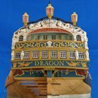 Fam got a reaction from Siggi52 in Le Colibri 1808 by Fam - scale 1:48 - POB French brick de 24
April 8th, 2016
Hi all
another quick update about the head-timber works.
The third couple of timbers is installed and the lower rail is being test-fitted in the next picture. Note that I had to complete the finish of the three head-timbers in their outer face, for the portion between the upper cheek and the rail, because the latter will obstruct the accessibility to this area for finishing. Therefore I glued a narrow strip of paper, blackened with a felt pen, inside the scraped molding and then re-touched with black acrylic paint to match the bow finish.
Here, in the two following shots, the two lower rails are completed and definitely installed. They are monolithic, i.e. built in a single piece, because their size and curvature are smaller and I thought they could be obtained from a single piece of wood.
Matching the rail with the three existing head-timbers, with the bow (between the hawse holes) and with the main rail was another “pleasant” task
And finally the fourth head-timber is completed and installed: it sits on top of the lower rail (where it touches the bow surface) and is connected to the main rail. All timbers are finished with the black strip on their outer face.
Forward platform
After completing the lower part of the ship’s head, I have switched to its upper side ... what I call “bowsprit deck” or “forward platform” (pretty sure the name is another, but I don’t know the correct English term).
Several cross timbers are laid in athwart direction connecting the two main head-rails. They are longitudinally positioned close to the head-timbers above described, but not precisely overlaid: there is a small shift forward and aft of the two forward-most timbers, to leave space for the bowsprit gammoning.
The timbers are intended to support a series of fore-and-aft smaller timbers (or “ledges”?), thus creating a sort of grating, or something that reproduces the carlings-ledges structure of the decks but with the scope of a grating.
Connection among the “ledges” parts and the athwart supports should be done with a series of recesses (notches) 1mm wide and 0.9mm spaced apart to each other, like visible on the wedge piece at the head-of-the-knee that I’ve already fixed.
The more proper way of doing this job is probably drawing reference longitudinal lines across the athwart beams and then cutting the teeth, with a sharp chisel or cutter, on their fore and aft upper edges. I thought that this method leaves large space for alignment imprecisions, any error in cutting the recesses would reflect in a deviation of the ledges from the F&A direction and from their parallelism. So decided for simulating this method by using instead the method shown here on MSW by Alexandru (Guraus’s buildlog of HMS Victory).
I built a step on the fore and aft upper edges of the athwart beams by overlaying two pieces: the lower is 3mm wide by 2mm thick, the upper batten is 2mm wide by 1mm thick: the resulting beam is a 3x3mm timber with two continuous 0.5x1mm steps along the upper edges, which will house the ledges timbers. In this way I will be able to take care of their correct alignment and spacing to each other.
The following picture shows the first two cross-beams installed: the steps are visible on the fore edges. Choice of material for the entire forward platform is a lighter shade of Pearwood (Swiss pearwood from CrownTimberyard company, great stuff!!), contrasting with the darker shade of the lower structures.
Once again, I couldn’t be happier of my decision to buy a disk sander (Proxxon TSG250/E in my case): once the proper angles needed to match the rails with the beams are found, with some trials, then obtaining the correct fitting for all the cross-beam timbers with the disk-sander is easy and fast, just a matter of few seconds! No need to say I strongly recommend this tool.
Here below the third, and last, cross-beam is positioned: it is longitudinally positioned so that it interferes with the stem, that seemed a bit weird to me. But after checking and measuring on the plans and verifying on the model, and then double-checking and measuring again, I got to the conclusion that its position is correct … or better it is compliant with the plans (supposing they are correct).
The problem with this position is that the beam, apart from crossing the stem, is not able to support the longitudinal grating. So I added another small piece just forward of the stem and connecting the two parts of the beam: probably not the correct solution, but I could not imagine another way out from this impasse. The building method for this cross-beam was the same, simply divided in two parts.
The first 5 longitudinal parts of the gratings (ledges) are also installed, to demonstrate the concept. They seem to be slightly not parallel, but it is just an impression from the picture: I ensure they are parallel!
And here again the forward platform at a later stage, with more ledges installed and two of the knees connecting the beams to the rails installed:
The knees are notched to match the beam step, then I will cut the recesses for the ledges in the after edge of each knee.
Finally a shot from the opposite side of the ship: the stern transom is finished in matt black and the moldings and decorations pop-out much more evident. I like very much the way light reflects on the Pearwood leaf decorations, giving them different shades of color that are only due to different orientation of the leaves.
Painting of the counter down to the second molding is not yet complete.
That’s all for today.
Best regards
Fam
-
 Fam got a reaction from Tadeusz43 in Le Colibri 1808 by Fam - scale 1:48 - POB French brick de 24
April 29th, 2016
No words ... just emotions to share
Fam
-
Fam got a reaction from Tadeusz43 in Le Colibri 1808 by Fam - scale 1:48 - POB French brick de 24
April 8th, 2016
Hi all
another quick update about the head-timber works.
The third couple of timbers is installed and the lower rail is being test-fitted in the next picture. Note that I had to complete the finish of the three head-timbers in their outer face, for the portion between the upper cheek and the rail, because the latter will obstruct the accessibility to this area for finishing. Therefore I glued a narrow strip of paper, blackened with a felt pen, inside the scraped molding and then re-touched with black acrylic paint to match the bow finish.
Here, in the two following shots, the two lower rails are completed and definitely installed. They are monolithic, i.e. built in a single piece, because their size and curvature are smaller and I thought they could be obtained from a single piece of wood.
Matching the rail with the three existing head-timbers, with the bow (between the hawse holes) and with the main rail was another “pleasant” task
And finally the fourth head-timber is completed and installed: it sits on top of the lower rail (where it touches the bow surface) and is connected to the main rail. All timbers are finished with the black strip on their outer face.
Forward platform
After completing the lower part of the ship’s head, I have switched to its upper side ... what I call “bowsprit deck” or “forward platform” (pretty sure the name is another, but I don’t know the correct English term).
Several cross timbers are laid in athwart direction connecting the two main head-rails. They are longitudinally positioned close to the head-timbers above described, but not precisely overlaid: there is a small shift forward and aft of the two forward-most timbers, to leave space for the bowsprit gammoning.
The timbers are intended to support a series of fore-and-aft smaller timbers (or “ledges”?), thus creating a sort of grating, or something that reproduces the carlings-ledges structure of the decks but with the scope of a grating.
Connection among the “ledges” parts and the athwart supports should be done with a series of recesses (notches) 1mm wide and 0.9mm spaced apart to each other, like visible on the wedge piece at the head-of-the-knee that I’ve already fixed.
The more proper way of doing this job is probably drawing reference longitudinal lines across the athwart beams and then cutting the teeth, with a sharp chisel or cutter, on their fore and aft upper edges. I thought that this method leaves large space for alignment imprecisions, any error in cutting the recesses would reflect in a deviation of the ledges from the F&A direction and from their parallelism. So decided for simulating this method by using instead the method shown here on MSW by Alexandru (Guraus’s buildlog of HMS Victory).
I built a step on the fore and aft upper edges of the athwart beams by overlaying two pieces: the lower is 3mm wide by 2mm thick, the upper batten is 2mm wide by 1mm thick: the resulting beam is a 3x3mm timber with two continuous 0.5x1mm steps along the upper edges, which will house the ledges timbers. In this way I will be able to take care of their correct alignment and spacing to each other.
The following picture shows the first two cross-beams installed: the steps are visible on the fore edges. Choice of material for the entire forward platform is a lighter shade of Pearwood (Swiss pearwood from CrownTimberyard company, great stuff!!), contrasting with the darker shade of the lower structures.
Once again, I couldn’t be happier of my decision to buy a disk sander (Proxxon TSG250/E in my case): once the proper angles needed to match the rails with the beams are found, with some trials, then obtaining the correct fitting for all the cross-beam timbers with the disk-sander is easy and fast, just a matter of few seconds! No need to say I strongly recommend this tool.
Here below the third, and last, cross-beam is positioned: it is longitudinally positioned so that it interferes with the stem, that seemed a bit weird to me. But after checking and measuring on the plans and verifying on the model, and then double-checking and measuring again, I got to the conclusion that its position is correct … or better it is compliant with the plans (supposing they are correct).
The problem with this position is that the beam, apart from crossing the stem, is not able to support the longitudinal grating. So I added another small piece just forward of the stem and connecting the two parts of the beam: probably not the correct solution, but I could not imagine another way out from this impasse. The building method for this cross-beam was the same, simply divided in two parts.
The first 5 longitudinal parts of the gratings (ledges) are also installed, to demonstrate the concept. They seem to be slightly not parallel, but it is just an impression from the picture: I ensure they are parallel!
And here again the forward platform at a later stage, with more ledges installed and two of the knees connecting the beams to the rails installed:
The knees are notched to match the beam step, then I will cut the recesses for the ledges in the after edge of each knee.
Finally a shot from the opposite side of the ship: the stern transom is finished in matt black and the moldings and decorations pop-out much more evident. I like very much the way light reflects on the Pearwood leaf decorations, giving them different shades of color that are only due to different orientation of the leaves.
Painting of the counter down to the second molding is not yet complete.
That’s all for today.
Best regards
Fam
-
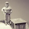 Fam got a reaction from kees de mol in Le Colibri 1808 by Fam - scale 1:48 - POB French brick de 24
For those who don't have access to the German forum where Johann is posting his work, I show here three steps describing what I'm trying to obtain (Johann if this is disturbing just let me know and I'll remove the images immediately):
- cast support parts for carronade barrel
- unassembled parts
- the completed carronade
All his pieces are brass, either lathed or cast. I was not so lucky, so all my parts will be cast in pewter. The final finish will be in gun-metal paint, polished with some lead pencil dust to improve the metallic look. The 9pdr long gun pictures I posted some time ago show what I mean.
I'd like to highlight that the design of my barrels seem to be exactly the same of Johann's, but I only referred to Ancre plans: probably the weapon was the same type for both ships, regardless of the different years of building.
Also note how the lower part of the carriage has no wheels, and carronade training is done by rotating the upper sledge ... this seems to be a little bit weird, but I don't have the knowledge to contest this layout.
Cheers
Fam