


Beef Wellington
-
Posts
2,245 -
Joined
-
Last visited
Reputation Activity
-

 Beef Wellington reacted to Blue Ensign in Muirneag 1903 by Blue Ensign – FINISHED - Vanguard Models - 1:64 scale - A Scottish Zulu Fishing Boat Based on the Vanguard Models Zulu Kit
Post 8
Completing the planking.
After a week of fairly concerted effort I am happy that my least liked aspect of assembly, the hull planking, is completed.
7183(2)
With nine strakes to go I added two strakes above the Garboard Plank.
From this point on it is simply a question of working the planks both upwards from the keel and down from the waterline.
The aim is to get the inevitable (in my case) final less regular shaped plank to sit on the underside of the hull curve.
7194(2)
One more to go.
During these last few strakes I re-check the planking runs and re-mark the tick strips several times.
7197(2)
The completed hull prior to sanding
Overall the supplied planking was satisfactory; a fair number of the planks did have an element of feathering on one edge, and some inconsistency in thickness along the length, but nothing that the sanding won’t sort out.
7206(2)
7207(2)
I use Pearwood dust sprinkled over pva to seal any slight gaps between the planking strakes.
7210(2)
7212
Starting to look better, but some fettlin’ still to go before I move onto the deck and the areas that interest me most on a build.
B.E.
19/09/2020
-
Beef Wellington reacted to Blue Ensign in Muirneag 1903 by Blue Ensign – FINISHED - Vanguard Models - 1:64 scale - A Scottish Zulu Fishing Boat Based on the Vanguard Models Zulu Kit
Post 6.
Second Planking.
This begins with the pre cut Garboard planks, another excellent idea from Chris.👍
Head scratching over the Garboard shape and extent of its length is something that happens to a lot of modellers, me included, and I’m grateful for its inclusion.
6959
The supplied patterns are a perfect fit requiring only a slight bevel to the keel edge. I also heat induced a slight twist to the plank to suit the hull shape along the keel.
6938
I used pva to fix these planks as I limit my use of ca to the minimum.
Moving onto the Pearwood planking.
It may be that Chris has already amended the manual but for those following it literally there is a narrative error in instruction 14. That may cause confusion.
6902
References to the planking starting at the main wale position markings, which are shown on the gunport patterns, obviously relates to another model.
The planking I assume starts along the top line of the bulwark pattern as with the Fifie model, and this is where I will start.
I sorted thro’ the stock of Pearwood strip and picked out the best strips matched for uniformity and colour.
I am primarily concerned with the planking down to the waterline about twelve strakes each side, as this will be simply sealed with wipe-on-poly.
In the end I decided to go with the supplied planking for my Cutter Alert Kit (which I didn’t use) and which has overall more consistent milling and a richer colour tone.
6944
The first three strakes down were fitted without taper, the Pearwood strip easily followed the sheer line, getting a close fit at the stem and stern posts is the main consideration.
6942
Below the second strake and my normal peg clamps don’t work, and the third strake is the limit of my modified peg clamps.
6945
The fourth strake down required a little edge bending towards the stern, but no tapering, and thanks to the large hatchway there is purchase to use the larger clamps.
6950
The fifth plank down requires both edge bend and taper at the stern.
6956
Beyond this point the option of clamps is removed so a degree of ca will be introduced at the bow and stern.
6955
The pre-formed Garboard plank can be seen running along the keel line.
6953
6965
Pre-fitting I do fine down the ends of the planks at the bow to reduce final sanding.
6960
With five strakes completed I will stop here and use the tick trip method to work out the remaining planking requirements before I continue.
B.E.
02.09/2020
-
Beef Wellington reacted to Blue Ensign in Muirneag 1903 by Blue Ensign – FINISHED - Vanguard Models - 1:64 scale - A Scottish Zulu Fishing Boat Based on the Vanguard Models Zulu Kit
Thank you Bob and Rusty, and to those who have looked in and 'liked'
Post 5
Preparing for second planking
With sanding of the first planking completed the stem piece and keel and stern pieces can be added.
I do rather like this method devised by Chris of having facing pieces in a nice wood which also provide a sort of rabbet for the second planking.
Slight set back as my assistant decided to practice some abstract canine carpentry on one of the keel strips that had fallen from my bench.
6976
Fortunately, a strip of Pearwood from the part retaining fret was available to make a replacement.
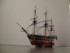
So here she is ready for the second planking, seems longer than the mere nine days since I actively started the project.
6920
Careful sanding down of the first layer around the bow and stern has allowed the ‘rabbets’ to provide sufficient edge to contain the second planking.
6925(2)
A first opportunity to compare the Fifie and Zulu side by side.
6908(2)
Sleeker than the Fifie and a tad longer, awaiting her transformation into a Swan.
6911(2)
They will make a fine complimentary pair representing the apex of the Scottish fishing industry of the early 20th century.
B.E.
29/08/20
-
Beef Wellington reacted to Blue Ensign in Muirneag 1903 by Blue Ensign – FINISHED - Vanguard Models - 1:64 scale - A Scottish Zulu Fishing Boat Based on the Vanguard Models Zulu Kit
Post 2
Preparing for planking
The first step is to complete the fairing and add the Bulwark patterns.
Fitting the bulwark patterns is a fairly painless exercise.
6706
Starting with the aft patterns soaking and wet fitting to form the shape using clamps to secure above decks, and bulkhead clamps for the lower edge.
6721
I use a hairdryer to speed up the process to establish shape memory, and the patterns can then be attached.
Only the area below the bulkhead tabs is glued, so again clamps only are used to hold the top line. The lower edge is pinned into the bulkheads.
6730
It helps to have everything to hand before starting, clamps, pins, pin pusher, and means to apply the glue.
6720
For positioning the pattern I use the lower of the two horizontal lines etched into the inside of the patterns, to align with the sub deck level.
This is something that was mentioned in the Fifie build, but not in the Zulu manual. In practice the top of the pattern mostly aligns with the tabs.
The Fore pattern bends easily around to the stem without the need for wetting. I did give it a blast of hot air whilst dry fitted and left it insitu overnight whilst the aft pattern was curing.
6726
The fore pattern on my build at least, was a perfect fit for length.
I temporarily fitted the stem post and the secondary stem piece to assist with alignment.
6733(2)
The distinctive sheer sweep to the stern now clearly apparent, plank tapering is going to be a significant feature of this build.
6731(2)
In this photo the stem piece is only dry fitted.
6739(2)
I now need to consider my approach to planking.
B.E.
22/08/20
-
Beef Wellington reacted to Blue Ensign in Muirneag 1903 by Blue Ensign – FINISHED - Vanguard Models - 1:64 scale - A Scottish Zulu Fishing Boat Based on the Vanguard Models Zulu Kit
Post 1
First Steps - the basics.
Usual stuff of assembling the false keel, bulkheads, and sub decks.
Note:
With the exception of the false keel (15) the other parts on the 3mm mdf sheet are numbered differently on the plan and in the manual.
There are similar differences on the Bulkhead sheet, but the bulkheads do accord.
6671
A minor confusion and irritation and perhaps something that needs addressing going forward.
I like to dry fit and fiddle around with the basic construction up to the fitting of the lower deck.
The bulkheads are a slightly looser fit than on my Fifie kit, and to ensure proper alignment, once lightly glued on the false keel I used the lower floor, Lower deck pattern, and Fore and aft filling patterns to keep things ship shape.
I initially glued the bulkheads 1-3 and then dry fitted the Fore filling pattern; followed by Bulkheads 10-14, secured by the Aft filling pattern; then the intervening bulkheads secured by the lower floor, and lower deck patterns.
6657
Any excess glue was removed from around the bulkheads before the dry fit items were put into place.
The first three and last three bulkheads are marked for an element of pre-fit bevelling, which was done before fitting.
As per the manual I also assembled the superstructure comprising a Poop deck, the companionway to the below cabin area, and Fish hatch, which is checked for fit in the lower deck.
6652
This structure won’t be needed for some time but is such that the fitting out of the Fish Hatch can be mostly done off model.
The Poop decking will not be put into place at this stage as I intend to open up the Companionway.
With the bulkheads fixed, the filling patterns are bevelled and glued into place, followed by the lower floor and deck pattern.
6665
The aft filling pattern is quite weak at its extreme end and one did snap during the bevelling process.
6667
Here temporarily supported until glued into place.
Fitting the aft filling patterns gave me the most trouble at this stage. The Starboard pattern simply wouldn’t fit down flush with the keel without a deal of fettling, the port side was easier to fit but still needed a little slot sanding.
I finally fitted them dry and ran diluted pva along the joints.
At this stage the stern extension and last three bulkheads present a point of weakness.
6660
There is a risk that this section could snap off if knocked, or even by heavy handed fairing of the last three bulkheads, which is best left until the sub deck is fitted.
The sub deck slotted between the bulkhead extensions without trouble and without any damage to the tabs.
6687(2)
The structure is now strong and rigid and can be handled with more confidence.
My final step in this stage is to add the rather nice Pearwood keel and stern post.
6695(2)
These slotted together and into the false keel with an excellent fit. As with the Fifie kit Chris has provided a number of keel alignment patterns, a simple but innovative idea.
6689(2)
Although shown in place here the manual calls for leaving the stem piece off until completion of the first planking;
I’m undecided about taking this approach, my natural instinct is to rabbet the stem piece.
Effectively the first planking needs to be reduced to a feather edge at the bow and stern to allow for the second planking to fit flush into the secondary stem piece which forms a rabbet for the Pearwood planking.
B.E.
21/08/20
-
 Beef Wellington got a reaction from mtaylor in HMS Bellerophon 1786 by fake johnbull - Amati/Victory Models - 1/72
Hi Mitsuaki, I really like the additional detailing that you have put into the channels and the chains. I have been considering taking the same approach for making the preventer links with wire. It's a small detail, but the results you have achieved are such an improvement on the flat kit supplied part and add so much to be beauty of the model.
-
 Beef Wellington got a reaction from mort stoll in HMS Bellerophon 1786 by fake johnbull - Amati/Victory Models - 1/72
Hi Mitsuaki, I really like the additional detailing that you have put into the channels and the chains. I have been considering taking the same approach for making the preventer links with wire. It's a small detail, but the results you have achieved are such an improvement on the flat kit supplied part and add so much to be beauty of the model.
-
 Beef Wellington got a reaction from drtrap in HMS Snake by Beef Wellington - FINISHED - Caldercraft - Scale 1: 64 - First wooden ship build
Hi Folks, have been away from the shipyard and this site for quite some time, and I've missed the friendly interaction. Looking forward to catching up with everyone's builds soon!
@Martin - welcome to the neighborhood! We got lucky and didn't lose power in the storms, hope you stayed safe. We definitely need to connect at some point so I can pick your brains 🙂
@ Sjors - Good to hear from you old friend, its been a while! Will check out your new model soon.
@ Stergios - the yards were rigged from bottom to top. Not sure if that is the recommended way, but it made sense to me to do that way because the lower masts require quite a few items of rigging to be in place near the mast and it seemed that this would be harder if the lines from the top masts were getting in the way. Maybe personal preference?
The cutter has finally been finished and the details of the final stages of construction are posted in my 'Jason' build log. Figuring out where to place the cutter onboard Snake was a little bit of a challenge. It seems inconceivable that a ship (sloop) like Snake would not have at least one boat, but there is simply no space to place one. I could find no examples of solutions to this in practice (recognizing that other ships may well have had raised davits), and it seems somewhat logical to mount the supports on the coamings which would also be supported by the deck beams underneath. Finally in position, its clear that even a modest 24' cutter has little room to spare.
With that done, now rigging can continue, hopefully some progress possible soon...
-
Beef Wellington reacted to Peterhudson in HMS DIANA by Peterhudson - Caldercraft - 1:64 Scale
I have been remiss in updating the blog. Apologies so here are a few catch up pictures. I have completed the main deck, securing all the cannons, carronades and deck fittings and am now moving on to the bowsprit and masts... Ill try to be a little more diligent with my updates. Peter
-
 Beef Wellington got a reaction from Jorge Diaz O in HMS Jason by Beef Wellington - Caldercraft - 1:64 - Artois-class frigate modified from HMS Diana 1794
Hi Folks,
Sadly been rather absent from both the shipyard and this site for some time. I very much hope to catch up soon on everyone else's fine builds here soon. Time to get a little more up to date, the cutter is pretty close to completion aside from a little fettling.
Frames were added to the interior using strips cut from some scrap 0.5mm pear wood. These were soaked and pre-bent in situ prior to gluing with PVA:
The frames were further reduced down to the keel former to try and get a bit more depth the boat. To my eye, applying planking to the false deck puts the board too high, especially as there is very little room to play with considering the various structural elements still to go on. A template for the footwaling was then made up to determine the shape. Once the placement was determined, the rising plank was added (again cut from some 0.5mm pear sheet)
I wanted to try and allow the footwalling to have an element of curvature which would be natural on the real boat. A relatively straightforward way to achieve this was to apply wood strip to thin card to match the template which maintains a lot of flexibility (Straight strip was used rather than the more complicated curved planking on the plan). Once dry, the assembly was easily glued on top of the keel former, the footwaling then follows the interior curve naturally.
With those element in place, it was possible to add the platform under the sternsheets. The Diana plans show these as a grating, but to my eye again the kit supplied grating is too large, so plain boards were installed instead which also appear to be used. After the main and fore mast steps, thwarts and ringbolts I assume would be used for hoisting the boat had been added, the bow was closed in using a cover as suggested on the plan - this also helped disguise the rudimentary construction at the bow. The rowlocks were cut, interestingly these are not symetrical between port and starboard, and one seems to sit rather awkwardly in the sternsheets.
The sternsheets were made up and installed, again having used a template to finalise shape, together with all the other details including mast thwarts, gunwale and knees.
The colour scheme follows a slightly simplified version of that shown below which seems suitably utilitarian. Looking at this, and comparing once the black was applied, suggests to me that I made a mistake in the tapering of the clinker planking. The black area covers both the wash strake and upper strake, and judging from these pictures it appears that these are of somewhat consistent in width, especially toward the stem. I had tapered these proportionally as well, hoping nobody else notices...
-
 Beef Wellington got a reaction from Timmo in HMS Jason by Beef Wellington - Caldercraft - 1:64 - Artois-class frigate modified from HMS Diana 1794
Hi Folks,
Sadly been rather absent from both the shipyard and this site for some time. I very much hope to catch up soon on everyone else's fine builds here soon. Time to get a little more up to date, the cutter is pretty close to completion aside from a little fettling.
Frames were added to the interior using strips cut from some scrap 0.5mm pear wood. These were soaked and pre-bent in situ prior to gluing with PVA:
The frames were further reduced down to the keel former to try and get a bit more depth the boat. To my eye, applying planking to the false deck puts the board too high, especially as there is very little room to play with considering the various structural elements still to go on. A template for the footwaling was then made up to determine the shape. Once the placement was determined, the rising plank was added (again cut from some 0.5mm pear sheet)
I wanted to try and allow the footwalling to have an element of curvature which would be natural on the real boat. A relatively straightforward way to achieve this was to apply wood strip to thin card to match the template which maintains a lot of flexibility (Straight strip was used rather than the more complicated curved planking on the plan). Once dry, the assembly was easily glued on top of the keel former, the footwaling then follows the interior curve naturally.
With those element in place, it was possible to add the platform under the sternsheets. The Diana plans show these as a grating, but to my eye again the kit supplied grating is too large, so plain boards were installed instead which also appear to be used. After the main and fore mast steps, thwarts and ringbolts I assume would be used for hoisting the boat had been added, the bow was closed in using a cover as suggested on the plan - this also helped disguise the rudimentary construction at the bow. The rowlocks were cut, interestingly these are not symetrical between port and starboard, and one seems to sit rather awkwardly in the sternsheets.
The sternsheets were made up and installed, again having used a template to finalise shape, together with all the other details including mast thwarts, gunwale and knees.
The colour scheme follows a slightly simplified version of that shown below which seems suitably utilitarian. Looking at this, and comparing once the black was applied, suggests to me that I made a mistake in the tapering of the clinker planking. The black area covers both the wash strake and upper strake, and judging from these pictures it appears that these are of somewhat consistent in width, especially toward the stem. I had tapered these proportionally as well, hoping nobody else notices...
-
Beef Wellington got a reaction from mtaylor in HM Brig-Sloop Flirt 1782 by Sjors - FINISHED - Vanguard Models - Scale 1:64
Great start Sjors and nice to see another of your model builds. Your planking looks great and you seem to have overcome the challenges on some of the details. This looks like an awesome kit.
-
.thumb.jpg.62d1d69fed1f32364417cb1f9cdeb009.jpg) Beef Wellington got a reaction from WalrusGuy in HMS Jason by Beef Wellington - Caldercraft - 1:64 - Artois-class frigate modified from HMS Diana 1794
Beef Wellington got a reaction from WalrusGuy in HMS Jason by Beef Wellington - Caldercraft - 1:64 - Artois-class frigate modified from HMS Diana 1794
Hi Folks,
Sadly been rather absent from both the shipyard and this site for some time. I very much hope to catch up soon on everyone else's fine builds here soon. Time to get a little more up to date, the cutter is pretty close to completion aside from a little fettling.
Frames were added to the interior using strips cut from some scrap 0.5mm pear wood. These were soaked and pre-bent in situ prior to gluing with PVA:
The frames were further reduced down to the keel former to try and get a bit more depth the boat. To my eye, applying planking to the false deck puts the board too high, especially as there is very little room to play with considering the various structural elements still to go on. A template for the footwaling was then made up to determine the shape. Once the placement was determined, the rising plank was added (again cut from some 0.5mm pear sheet)
I wanted to try and allow the footwalling to have an element of curvature which would be natural on the real boat. A relatively straightforward way to achieve this was to apply wood strip to thin card to match the template which maintains a lot of flexibility (Straight strip was used rather than the more complicated curved planking on the plan). Once dry, the assembly was easily glued on top of the keel former, the footwaling then follows the interior curve naturally.
With those element in place, it was possible to add the platform under the sternsheets. The Diana plans show these as a grating, but to my eye again the kit supplied grating is too large, so plain boards were installed instead which also appear to be used. After the main and fore mast steps, thwarts and ringbolts I assume would be used for hoisting the boat had been added, the bow was closed in using a cover as suggested on the plan - this also helped disguise the rudimentary construction at the bow. The rowlocks were cut, interestingly these are not symetrical between port and starboard, and one seems to sit rather awkwardly in the sternsheets.
The sternsheets were made up and installed, again having used a template to finalise shape, together with all the other details including mast thwarts, gunwale and knees.
The colour scheme follows a slightly simplified version of that shown below which seems suitably utilitarian. Looking at this, and comparing once the black was applied, suggests to me that I made a mistake in the tapering of the clinker planking. The black area covers both the wash strake and upper strake, and judging from these pictures it appears that these are of somewhat consistent in width, especially toward the stem. I had tapered these proportionally as well, hoping nobody else notices...
-
 Beef Wellington got a reaction from Barbossa in HMS Jason by Beef Wellington - Caldercraft - 1:64 - Artois-class frigate modified from HMS Diana 1794
Hi Folks,
Sadly been rather absent from both the shipyard and this site for some time. I very much hope to catch up soon on everyone else's fine builds here soon. Time to get a little more up to date, the cutter is pretty close to completion aside from a little fettling.
Frames were added to the interior using strips cut from some scrap 0.5mm pear wood. These were soaked and pre-bent in situ prior to gluing with PVA:
The frames were further reduced down to the keel former to try and get a bit more depth the boat. To my eye, applying planking to the false deck puts the board too high, especially as there is very little room to play with considering the various structural elements still to go on. A template for the footwaling was then made up to determine the shape. Once the placement was determined, the rising plank was added (again cut from some 0.5mm pear sheet)
I wanted to try and allow the footwalling to have an element of curvature which would be natural on the real boat. A relatively straightforward way to achieve this was to apply wood strip to thin card to match the template which maintains a lot of flexibility (Straight strip was used rather than the more complicated curved planking on the plan). Once dry, the assembly was easily glued on top of the keel former, the footwaling then follows the interior curve naturally.
With those element in place, it was possible to add the platform under the sternsheets. The Diana plans show these as a grating, but to my eye again the kit supplied grating is too large, so plain boards were installed instead which also appear to be used. After the main and fore mast steps, thwarts and ringbolts I assume would be used for hoisting the boat had been added, the bow was closed in using a cover as suggested on the plan - this also helped disguise the rudimentary construction at the bow. The rowlocks were cut, interestingly these are not symetrical between port and starboard, and one seems to sit rather awkwardly in the sternsheets.
The sternsheets were made up and installed, again having used a template to finalise shape, together with all the other details including mast thwarts, gunwale and knees.
The colour scheme follows a slightly simplified version of that shown below which seems suitably utilitarian. Looking at this, and comparing once the black was applied, suggests to me that I made a mistake in the tapering of the clinker planking. The black area covers both the wash strake and upper strake, and judging from these pictures it appears that these are of somewhat consistent in width, especially toward the stem. I had tapered these proportionally as well, hoping nobody else notices...
-
Beef Wellington got a reaction from WalrusGuy in HMS Snake by Beef Wellington - FINISHED - Caldercraft - Scale 1: 64 - First wooden ship build
Hi Folks, have been away from the shipyard and this site for quite some time, and I've missed the friendly interaction. Looking forward to catching up with everyone's builds soon!
@Martin - welcome to the neighborhood! We got lucky and didn't lose power in the storms, hope you stayed safe. We definitely need to connect at some point so I can pick your brains 🙂
@ Sjors - Good to hear from you old friend, its been a while! Will check out your new model soon.
@ Stergios - the yards were rigged from bottom to top. Not sure if that is the recommended way, but it made sense to me to do that way because the lower masts require quite a few items of rigging to be in place near the mast and it seemed that this would be harder if the lines from the top masts were getting in the way. Maybe personal preference?
The cutter has finally been finished and the details of the final stages of construction are posted in my 'Jason' build log. Figuring out where to place the cutter onboard Snake was a little bit of a challenge. It seems inconceivable that a ship (sloop) like Snake would not have at least one boat, but there is simply no space to place one. I could find no examples of solutions to this in practice (recognizing that other ships may well have had raised davits), and it seems somewhat logical to mount the supports on the coamings which would also be supported by the deck beams underneath. Finally in position, its clear that even a modest 24' cutter has little room to spare.
With that done, now rigging can continue, hopefully some progress possible soon...
-
Beef Wellington reacted to dafi in HMS Victory by dafi - Heller - PLASTIC - To Victory and beyond ...
Thank you Gary and druxey.
Very nice detail the small flap. Could it also be to protect the bar from the side effects of the shot? Often the ports for the carronades were higher in size for that reason.
Also I realised the bolster being extended forward. My interpretation was - as I realisd it mostely underneath gunports - that it would perhaps allow an temporary extension for the board. The step is a great explanation too. I do not think this was for sounding the lead I know it being done out of the channels or another small platform amidship. There too the breaststrap could be fixed more easily that allowed the men to lean against and have the hands free.
Difficult to be seen, but the strap is there 🙂
XXXDAn
-
Beef Wellington reacted to dafi in HMS Victory by dafi - Heller - PLASTIC - To Victory and beyond ...
So the trilogy of the 4 slices is almost done 🙂
- 1765 to 1780 (as build)
- September 1805 mid Atlantic on the chase of Villeneuve
- 1920 before docking
- and the latest revamp 2018
Still have to make a nice frame.
XXXDAn
-
 Beef Wellington got a reaction from DmitriyMarkov in HMS Jason by Beef Wellington - Caldercraft - 1:64 - Artois-class frigate modified from HMS Diana 1794
Hi Folks,
Sadly been rather absent from both the shipyard and this site for some time. I very much hope to catch up soon on everyone else's fine builds here soon. Time to get a little more up to date, the cutter is pretty close to completion aside from a little fettling.
Frames were added to the interior using strips cut from some scrap 0.5mm pear wood. These were soaked and pre-bent in situ prior to gluing with PVA:
The frames were further reduced down to the keel former to try and get a bit more depth the boat. To my eye, applying planking to the false deck puts the board too high, especially as there is very little room to play with considering the various structural elements still to go on. A template for the footwaling was then made up to determine the shape. Once the placement was determined, the rising plank was added (again cut from some 0.5mm pear sheet)
I wanted to try and allow the footwalling to have an element of curvature which would be natural on the real boat. A relatively straightforward way to achieve this was to apply wood strip to thin card to match the template which maintains a lot of flexibility (Straight strip was used rather than the more complicated curved planking on the plan). Once dry, the assembly was easily glued on top of the keel former, the footwaling then follows the interior curve naturally.
With those element in place, it was possible to add the platform under the sternsheets. The Diana plans show these as a grating, but to my eye again the kit supplied grating is too large, so plain boards were installed instead which also appear to be used. After the main and fore mast steps, thwarts and ringbolts I assume would be used for hoisting the boat had been added, the bow was closed in using a cover as suggested on the plan - this also helped disguise the rudimentary construction at the bow. The rowlocks were cut, interestingly these are not symetrical between port and starboard, and one seems to sit rather awkwardly in the sternsheets.
The sternsheets were made up and installed, again having used a template to finalise shape, together with all the other details including mast thwarts, gunwale and knees.
The colour scheme follows a slightly simplified version of that shown below which seems suitably utilitarian. Looking at this, and comparing once the black was applied, suggests to me that I made a mistake in the tapering of the clinker planking. The black area covers both the wash strake and upper strake, and judging from these pictures it appears that these are of somewhat consistent in width, especially toward the stem. I had tapered these proportionally as well, hoping nobody else notices...
-
 Beef Wellington got a reaction from Blue Ensign in HMS Snake by Beef Wellington - FINISHED - Caldercraft - Scale 1: 64 - First wooden ship build
Hi Folks, have been away from the shipyard and this site for quite some time, and I've missed the friendly interaction. Looking forward to catching up with everyone's builds soon!
@Martin - welcome to the neighborhood! We got lucky and didn't lose power in the storms, hope you stayed safe. We definitely need to connect at some point so I can pick your brains 🙂
@ Sjors - Good to hear from you old friend, its been a while! Will check out your new model soon.
@ Stergios - the yards were rigged from bottom to top. Not sure if that is the recommended way, but it made sense to me to do that way because the lower masts require quite a few items of rigging to be in place near the mast and it seemed that this would be harder if the lines from the top masts were getting in the way. Maybe personal preference?
The cutter has finally been finished and the details of the final stages of construction are posted in my 'Jason' build log. Figuring out where to place the cutter onboard Snake was a little bit of a challenge. It seems inconceivable that a ship (sloop) like Snake would not have at least one boat, but there is simply no space to place one. I could find no examples of solutions to this in practice (recognizing that other ships may well have had raised davits), and it seems somewhat logical to mount the supports on the coamings which would also be supported by the deck beams underneath. Finally in position, its clear that even a modest 24' cutter has little room to spare.
With that done, now rigging can continue, hopefully some progress possible soon...
-
 Beef Wellington got a reaction from cog in HMS Jason by Beef Wellington - Caldercraft - 1:64 - Artois-class frigate modified from HMS Diana 1794
Hi Folks,
Sadly been rather absent from both the shipyard and this site for some time. I very much hope to catch up soon on everyone else's fine builds here soon. Time to get a little more up to date, the cutter is pretty close to completion aside from a little fettling.
Frames were added to the interior using strips cut from some scrap 0.5mm pear wood. These were soaked and pre-bent in situ prior to gluing with PVA:
The frames were further reduced down to the keel former to try and get a bit more depth the boat. To my eye, applying planking to the false deck puts the board too high, especially as there is very little room to play with considering the various structural elements still to go on. A template for the footwaling was then made up to determine the shape. Once the placement was determined, the rising plank was added (again cut from some 0.5mm pear sheet)
I wanted to try and allow the footwalling to have an element of curvature which would be natural on the real boat. A relatively straightforward way to achieve this was to apply wood strip to thin card to match the template which maintains a lot of flexibility (Straight strip was used rather than the more complicated curved planking on the plan). Once dry, the assembly was easily glued on top of the keel former, the footwaling then follows the interior curve naturally.
With those element in place, it was possible to add the platform under the sternsheets. The Diana plans show these as a grating, but to my eye again the kit supplied grating is too large, so plain boards were installed instead which also appear to be used. After the main and fore mast steps, thwarts and ringbolts I assume would be used for hoisting the boat had been added, the bow was closed in using a cover as suggested on the plan - this also helped disguise the rudimentary construction at the bow. The rowlocks were cut, interestingly these are not symetrical between port and starboard, and one seems to sit rather awkwardly in the sternsheets.
The sternsheets were made up and installed, again having used a template to finalise shape, together with all the other details including mast thwarts, gunwale and knees.
The colour scheme follows a slightly simplified version of that shown below which seems suitably utilitarian. Looking at this, and comparing once the black was applied, suggests to me that I made a mistake in the tapering of the clinker planking. The black area covers both the wash strake and upper strake, and judging from these pictures it appears that these are of somewhat consistent in width, especially toward the stem. I had tapered these proportionally as well, hoping nobody else notices...
-
Beef Wellington reacted to BenD in HMS Snake by BenD - Caldercraft - 1:64
I've been working on all the deck features. Nothing is glued in yet as there is a lot more work to be done. Next up is the fore and aft platforms.
-
Beef Wellington reacted to BenD in HMS Snake by BenD - Caldercraft - 1:64
I upgraded my workstation once again. This time I got a new desk and some cheap Ikea lamps that can use 800 lumens bulbs. I now have more desk space than I know what to do with.
So many hours have gone into prepping parts and painting for the Carronades. I can't even begin to imagine doing all the guns for a frigate or a ship of the line. Anyway I tried using a black deckblock to see If I liked the contrast or not, backed out of that pretty fast.
-
 Beef Wellington got a reaction from KARAVOKIRIS in HMS Snake by Beef Wellington - FINISHED - Caldercraft - Scale 1: 64 - First wooden ship build
Hi Folks, have been away from the shipyard and this site for quite some time, and I've missed the friendly interaction. Looking forward to catching up with everyone's builds soon!
@Martin - welcome to the neighborhood! We got lucky and didn't lose power in the storms, hope you stayed safe. We definitely need to connect at some point so I can pick your brains 🙂
@ Sjors - Good to hear from you old friend, its been a while! Will check out your new model soon.
@ Stergios - the yards were rigged from bottom to top. Not sure if that is the recommended way, but it made sense to me to do that way because the lower masts require quite a few items of rigging to be in place near the mast and it seemed that this would be harder if the lines from the top masts were getting in the way. Maybe personal preference?
The cutter has finally been finished and the details of the final stages of construction are posted in my 'Jason' build log. Figuring out where to place the cutter onboard Snake was a little bit of a challenge. It seems inconceivable that a ship (sloop) like Snake would not have at least one boat, but there is simply no space to place one. I could find no examples of solutions to this in practice (recognizing that other ships may well have had raised davits), and it seems somewhat logical to mount the supports on the coamings which would also be supported by the deck beams underneath. Finally in position, its clear that even a modest 24' cutter has little room to spare.
With that done, now rigging can continue, hopefully some progress possible soon...
-
 Beef Wellington got a reaction from Sjors in HMS Jason by Beef Wellington - Caldercraft - 1:64 - Artois-class frigate modified from HMS Diana 1794
Many thanks all for the comments and likes, definitely good to have people along for the journey..
Feels like a chapter is coming to a close, finally seem to be closing in on completing the upper deck. Definitely a multitude of time consuming small tasks. First off I needed to address the fixed part of the gangway. This is shown quite clearly in plan view on page 46 of AOTS Diana, however it is not shown in profile. Given that it appears to contain its own lodging knee, I decided to extend the profile of the deck beam. This seems to make sense when recognizing that a ladder will eventually be located here. This highlights one of the inconsistencies in the AOTS book, many diagrams show the non-flush gangboards which I understand were going out of fashion at this point to be replaced by flush gangboards. Hoping I'm not too far off the mark here. A strip with a slight profile was added also to the deck beam to sit flush with the false quarterdeck.
The base plate to the stove was ripped off and replaced despite my intentions to leave as, hopefully this sits a little more harmoniously.
Cables have been added and "secured" to the various ring bolts beside the midship gratings. AOTS describes these as being used for stoppers, but decided to secure with simpler ring ropes as described in Lever. Stoppers have been modelled as per Lever on the 2 foremost ring bolts, but not yet tied on or attached permanently to allow me to finally decide (or others to refute) the approach taken.
Even though this area will only ever be glimpsed, time was spent fully building out the area around the foremast with the For jeer and for topsail sheet bitts as they would appear. The actual bitts on the fo'c'sl will be mounted to the deck, seemed unnecessarily complicated to build these fully. Couldn't quite figure out what was represented on diagrams for the fore jeer bitts until I saw interior photos of contemporary models in the Roger's Dockyard Model collection - but still no clue what the "swan neck" arrangement is called. What is very interesting is how crowded this forward area really is, fighting these guns must have been a real challenge.
Warning: Here follows some highly indulgent closeups taken on Captain's rounds! This is the closest I guess I'll get to seeing what this looked like in practice
And finally...some overall shots with where things stand..
-
Beef Wellington got a reaction from Sjors in HMS Jason by Beef Wellington - Caldercraft - 1:64 - Artois-class frigate modified from HMS Diana 1794
Quick update. Increasingly realizing I'm reaching a point that I need to attach the upper false foc's'l and quarter deck template before more progress can be made, but a couple of items I need to finalize and figure out first.
Main and mizzen backstay stools:
Unfortunately when I made the channels I neglected to make the stools at the same time, In a moment of focus decided to just get these done. These smaller items were definitely trickier than the channels when scraping the edge profile, other than that, these can be put aside for when I'm ready to install the quarterdeck drift rail.
Upper deck coamings:
As mentioned previously, I'd like to keep the option to have a few of the gratings be removeable. First off, appropriately sized gratings were made up, and the coamings then sized accordingly. I cheated here and used a simple butt joint as I didn't think the more authentic lap joint would really be visible. These were made of 3x3mm strip and 2x3mm strip with the inside ledge added after with some slightly thinned 1mm strip. The grating thickness had to be thinned quite a bit to make it them sit flush. These will also be simulating actual practice and so the edges were rounded off to 1mm above the bottom to butt up against planking. TFFM was used as a guide here.
Once the coamings were finished, the fake beams and cross pieces could be made up to the appropriate size. The ends were sloped to ensure that the end of the face beam would not be visible for viewing angles.
Adjustments were made to the false deck to accommodate the larger openings and positions tweaked a little. For the foc's'l, the coaming size does not match the deck cut-out or AOTS exactly due to the limited incremental options for the grating size. The stove flue needs to sit equidistant between the steam grate and the forward grating which moved forward slightly. The steam grating needs to be positioned appropriately to allow the belfy to sit on the aft end of the steam grate coaming.
The top tackle scuttles have been filled in to ease future planking - the instructions indicate that there should be coamings and gratings here, however, these will be modeled as flush scuppers without a coaming as described in AOTS and shown on contemporary models. Although the surface of the center deck is very slightly curved, it is a close enough approximation to a flat surface that the flat top of the fake frame seem to sit without issue. Lighting is clearly an issue here, and the interior is a little more visible than the photo's suggest, and probably more so in a well lit room.
Of note is the fact that the stove, and especially the condenser, sits a little higher than ideally would be the case, although looking at the AOTS diagrams its still a tight fit there as well. In retrospect, I would probably not have put wooden battens underneath the bottom plate to lower this by 1mm or so, but not going to risk damage at this point to redo.
Putting some scrap planking in place give a better sense for the final proportion and the above deck rounded edge. Think these will be a nice contrast to the much higher coamings of the exposed upper deck below needed to withstand water ingress.