


Beef Wellington
-
Posts
2,245 -
Joined
-
Last visited
Reputation Activity
-

 Beef Wellington reacted to Dan Vadas in IJN Amatsukaze by Dan Vadas - FINISHED - Halinski - 1:200 scale - CARD and Brass - WW2 Japanese Destroyer -
Hah, that's nearly exactly what I did , and I also used a Q-tip dipped in Acetone to go over each one when the paint was almost dry. This took a little of the paint off, allowing some of the original to show through, and taking all the shine off it as well.
I've finished the red touch-up, masked the grey (which I haven't touched up yet) and gave the hull two coats of Testor's Dullcote. The difference is extraordinary - you really have to look hard to see any of the touch-ups. The only ones that stand out a little bit are a couple that I'd done with a slightly darker shade of red near the stern. I'm more than happy with the result .
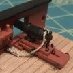
I've fitted the Bilge Keels. I had to think a bit on a way of holding them in position and came up with the following. There is a thin printed line to follow, so I used some Tamiya tape to make it easier to see as it would have been hidden once the keel went on :
Next I shaped a strip of balsa to follow the curvature and taped it to the hull :
I taped and clamped the keel to the balsa strip and ran a bead of glue on the edge closest to the centre of the ship so it won't be seen when the ship is the right way up :
The finished job. You can see the touch-ups on the gaps (or not ) :
Danny
-
Beef Wellington reacted to toms10 in HMS Leopard by toms10 - FINISHED - 1:85 scale POF/POB
Now that the summer weather is here progress will slow for sure but I have been playing with some LED lights and started putting some in to illuminate some of the visible details of the lower decks. I drilled a lot of holes for the wires to snake through the frames. The idea will be to have them joined between the frames just above where the rear display pedestal will be located. A single set of wires will come out through the keel and through the center of the pedestal. I will figure out how to hide these in the case when I start building that in a few years. Right now just for testing the positioning and intensities the wires are just dangling all over. Can pretty that up later.
The light on the left of the uppermost deck shown (lower gun deck) is not fixed in place yet so the camera picked up the glare because the bulb are still visible. I will position it in the aft corner on the starboard side so it won't be visible when looking in.
Here is the portside without the cannons coming through the gun ports yet. Looked kind of neat so I thought I would share the picture.
The final plan is to have the stern galleries lit up as well and the 2 stern lights. It is going to be a lot of work and time... uh, I mean fun... but worth it in the end.
Tom
-
Beef Wellington reacted to toms10 in HMS Leopard by toms10 - FINISHED - 1:85 scale POF/POB
Hello all,
I have not posted in a while but I have been picking away at odds and ends. I finish sanded the outer planking above the wales, moved a gunport that was in the wrong location... but we won't talk about that much. I mistook a centerline of the port for the edge and it ended up a 1/2 port too much aft. It was the gun port just forward of where the stairs on the outside hull would be. On the picture above (post #95) it was the 6th one from the bow on the port side. It needed to be moved forward. That is now behind me and only the people who read this post will know. All the port linings are finished and now I am dry fitting the deck beams for the upper gun deck. Things are going a bit slower now that the weather is pretty nice and other hobbies are kicking in. Just wondering, is spring yard clean up considered a hobby??? I have been waiting for the "yard fairies" to show up but it doesn't look promising.
I also need to start figuring out how I am going to get my Constellation to the Northeast Ship Modelers Show in New London, CT at the end of the month.
Start building and dry fitting the upper deck beams.
Tom
-
Beef Wellington reacted to ken3335 in Royal William by ken3335 - FINISHED - Euromodel - Scale 1:72
Hi Mustafa, Thanks, welcome aboard my log.
I said that I only had minor tweaks to finish this part off, well they took me the rest of the day, no quick fixes I'm afraid. I've now glued the two pieces together but just slotted the casting in place so now I have a good idea of how it will look. I've shown a picture of how it sits at what will be its final position. A little filler will be needed but as it will be painted I'm ok with that.
ken
-
Beef Wellington reacted to ken3335 in Royal William by ken3335 - FINISHED - Euromodel - Scale 1:72
Hello Everyone. As you'll see I've had another busy time at the shipyard. It's come along so well that I'm actually grinning at the thought of showing it off. As I mentioned earlier, until the hull is sanded it looks a bit rough and you don't get that thrill of seeing what it's eventually going to look like, but now!
I gave it a good sanding, there were a few seams that I rubbed some filler in to try and get it as good as I could. I cut out the grooves for the stem, keel and sternpost, made them up and fitted them. I'd not done it like this before but had a good feeling that it was the way to go. I'm delighted at the result and don't think that I could have had as neat a result if I had tried to butt the planks against the prow and stern. I decided to stain the hull to give the wood a slightly warmer than walnut look. I rubbed in some light teak stain, this gave it a slight honey coloured tone a bit like pear, it also brought out the grain so again I was pleased. I think that I'll give it a coat of sanding sealer so that the nice surface doesn't get any stains on it that I won't be able to remove.
I am now in a dilemma, whilst I realise that it will never be used as an example of how a model ship should be planked I am so pleased with the way it looks that I am now undecided whether to leave it bare showing off the wood or to paint it as had originally intended. Hmm! thoughts on this please.
I am now nearing the part of the build that I am dreading most, The stern gallery support and the galleries themselves. Mark in his log gives an excellent account with good pictures of how he accomplished his galleries but until I start I have doubts on how I'm actually going to get this done, I've got a couple of pre shaped pieces of wood, the third and thinnest was missing so I made one up off the plan and I'm now wondering where to start?
Ken
-
 Beef Wellington got a reaction from mtaylor in HMS Jason by Beef Wellington - Caldercraft - 1:64 - Artois-class frigate modified from HMS Diana 1794
Thanks everyone for the encouraging comments.
@Carl - I looked at Baskerville, before you posted this I decided to follow Perpetua Titling as a guide as it is probably the closest to whats seen on Victory that I could find, Baskerville looks good as well. There is one problem with all these fonts, and that is the "J", in nearly all of these older fonts the J drops below the level of the other letters (it is invariably the only one to do that) which I don't think is how it would be done. I've decided to us the 'Castella' font as a guide for the J, as the other letters are similar stylistically but a little thicker.
However, there is a big caveat here, given that I'm choosing to paint the letters so despite lofty ideas I still need to execute that somehow, and I doubt my skills are up to this level of accuracy or refinement and I'm keeping my expectations at an appropriate level. I think it would be a good game afterwards to play 'guess' the font because I know it will not be as pure as the printed examples.
-
 Beef Wellington got a reaction from CiscoH in HMS Jason by Beef Wellington - Caldercraft - 1:64 - Artois-class frigate modified from HMS Diana 1794
Thomas, Bob, Eamonn, Pat and Mark (nice to have you back!) - thanks for the comments guys and the likes, I very much appreciate your interest.
The upper counter and the proof of the pudding...
Finally plucked up the courage to attach the stern fascia, really have done about as much on this as I can before fitting, and any final adjustments should be done in place to get a proper feel for the various lines and angles and how this will fit with the side galleries (esp. out edge and gunports). Epoxy was used for maximum strength, so it better be right. It all went pretty painlessly as the placement had already been determined.
Then comes the upper counter...this should simply fit between the edge of the upper counter and the stern fascia. I have been planning to use a single piece of 1mm pear for this (I think the kit instructions indicate for this to be planked) and I didn't relax for the whole weekend while I worked on this part. Philosophically, it is what it is at this point as I had done everything I could think of to ensure this fitted well.
After making a template for the upper counter and leaving material to allow for fine tuning, the lower edge of the stern fascia (where the upper counter rail will go), was chamfered back to receive the upper counter and ensure the correct angle to the vertical along its length.
The edge of the upper counter was then gradually chamfered to meet this angle. I found using a razor blade scraper a very effective way to do this as it kept a nice flat profile and allow the angle with the stern fascia to be followed easily. I had painted the upper counter prior to this process to give a better feel for the shape during this process. (The lower edge was simply masked so the lower counter rail can be glued more easily as I prefer to use PVA glue). The profile at the end shows how this fitted together.
Only one potential problem remained. The face with the join needs to be the same width as the upper counter rail (3mm) which required many, small adjustments. See photo below for how the various rails will be positioned.
This is not glued yet, but the overall I was very happy with the way this turned out, and 2 small pegs are all that's needed to keep it in position. Before this is attached I need to figure out how to apply the name, at this point I'm leaning toward painting this. I've been playing with some templates made in Powerpoint to just get a sense for size and alignment. This is Time New Roman, 50pt font with y-rotation of 340% and 100% perspective adjustment. I now feel I have proper ship under construction.
As always, suggestions welcome!
-
Beef Wellington reacted to cog in HMS Jason by Beef Wellington - Caldercraft - 1:64 - Artois-class frigate modified from HMS Diana 1794
Jason,
Considering the shape of the font of e.g. HMS Victory, I would sooner go for Baskerville, if you need the font, let me know
-
Beef Wellington reacted to mcpwilk in HMS Jason by Beef Wellington - Caldercraft - 1:64 - Artois-class frigate modified from HMS Diana 1794
Beautifully done.
Mike
-
Beef Wellington reacted to Blue Ensign in HMS Jason by Beef Wellington - Caldercraft - 1:64 - Artois-class frigate modified from HMS Diana 1794
Beautiful work Jason, the headworks shots so clearly show the purity of your work.
A wonderful build.
B.E.
-
Beef Wellington reacted to Timmo in HMS Jason by Beef Wellington - Caldercraft - 1:64 - Artois-class frigate modified from HMS Diana 1794
That name looks great Jason and the cheeks and other stem work is fantastic. Well done.
-
 Beef Wellington got a reaction from BenD in HMS Jason by Beef Wellington - Caldercraft - 1:64 - Artois-class frigate modified from HMS Diana 1794
Thomas, Bob, Eamonn, Pat and Mark (nice to have you back!) - thanks for the comments guys and the likes, I very much appreciate your interest.
The upper counter and the proof of the pudding...
Finally plucked up the courage to attach the stern fascia, really have done about as much on this as I can before fitting, and any final adjustments should be done in place to get a proper feel for the various lines and angles and how this will fit with the side galleries (esp. out edge and gunports). Epoxy was used for maximum strength, so it better be right. It all went pretty painlessly as the placement had already been determined.
Then comes the upper counter...this should simply fit between the edge of the upper counter and the stern fascia. I have been planning to use a single piece of 1mm pear for this (I think the kit instructions indicate for this to be planked) and I didn't relax for the whole weekend while I worked on this part. Philosophically, it is what it is at this point as I had done everything I could think of to ensure this fitted well.
After making a template for the upper counter and leaving material to allow for fine tuning, the lower edge of the stern fascia (where the upper counter rail will go), was chamfered back to receive the upper counter and ensure the correct angle to the vertical along its length.
The edge of the upper counter was then gradually chamfered to meet this angle. I found using a razor blade scraper a very effective way to do this as it kept a nice flat profile and allow the angle with the stern fascia to be followed easily. I had painted the upper counter prior to this process to give a better feel for the shape during this process. (The lower edge was simply masked so the lower counter rail can be glued more easily as I prefer to use PVA glue). The profile at the end shows how this fitted together.
Only one potential problem remained. The face with the join needs to be the same width as the upper counter rail (3mm) which required many, small adjustments. See photo below for how the various rails will be positioned.
This is not glued yet, but the overall I was very happy with the way this turned out, and 2 small pegs are all that's needed to keep it in position. Before this is attached I need to figure out how to apply the name, at this point I'm leaning toward painting this. I've been playing with some templates made in Powerpoint to just get a sense for size and alignment. This is Time New Roman, 50pt font with y-rotation of 340% and 100% perspective adjustment. I now feel I have proper ship under construction.
As always, suggestions welcome!
-
 Beef Wellington got a reaction from coxswain in HMS Jason by Beef Wellington - Caldercraft - 1:64 - Artois-class frigate modified from HMS Diana 1794
Thomas, Bob, Eamonn, Pat and Mark (nice to have you back!) - thanks for the comments guys and the likes, I very much appreciate your interest.
The upper counter and the proof of the pudding...
Finally plucked up the courage to attach the stern fascia, really have done about as much on this as I can before fitting, and any final adjustments should be done in place to get a proper feel for the various lines and angles and how this will fit with the side galleries (esp. out edge and gunports). Epoxy was used for maximum strength, so it better be right. It all went pretty painlessly as the placement had already been determined.
Then comes the upper counter...this should simply fit between the edge of the upper counter and the stern fascia. I have been planning to use a single piece of 1mm pear for this (I think the kit instructions indicate for this to be planked) and I didn't relax for the whole weekend while I worked on this part. Philosophically, it is what it is at this point as I had done everything I could think of to ensure this fitted well.
After making a template for the upper counter and leaving material to allow for fine tuning, the lower edge of the stern fascia (where the upper counter rail will go), was chamfered back to receive the upper counter and ensure the correct angle to the vertical along its length.
The edge of the upper counter was then gradually chamfered to meet this angle. I found using a razor blade scraper a very effective way to do this as it kept a nice flat profile and allow the angle with the stern fascia to be followed easily. I had painted the upper counter prior to this process to give a better feel for the shape during this process. (The lower edge was simply masked so the lower counter rail can be glued more easily as I prefer to use PVA glue). The profile at the end shows how this fitted together.
Only one potential problem remained. The face with the join needs to be the same width as the upper counter rail (3mm) which required many, small adjustments. See photo below for how the various rails will be positioned.
This is not glued yet, but the overall I was very happy with the way this turned out, and 2 small pegs are all that's needed to keep it in position. Before this is attached I need to figure out how to apply the name, at this point I'm leaning toward painting this. I've been playing with some templates made in Powerpoint to just get a sense for size and alignment. This is Time New Roman, 50pt font with y-rotation of 340% and 100% perspective adjustment. I now feel I have proper ship under construction.
As always, suggestions welcome!
-
 Beef Wellington got a reaction from chris watton in HMS Jason by Beef Wellington - Caldercraft - 1:64 - Artois-class frigate modified from HMS Diana 1794
Carl, Rob, Christian, Niles and the likes - thanks for your kind words, encouragement and patience on this slow voyage...
Jesse, Dave - Of course you are right, but no matter how many times I tell myself that it doesn't help...I probably have one of those personality disorders along the lines of "well he did it, so why can't I?" And yes, its gets me into trouble with those fixes around the house that I maybe shouldn't be tackling..
Anyway a little update as I really can do no more to the bow at this point, which means I need to get back to the stern...then I remembered that that was basically the reason for me taking a break and starting work on the bow...There are a couple of questions at the end.
Once the cheeks and the rails were done, I needed to tackle hawse holes and the bolsters. These had me really thinking, but first step was once again to shape from some thick stock, only this time I had to take it even slower as pretty much the entire interior face needed to fit tightly against the hull because any errors would be really obvious once the holes were cut. The balsa filler blocks were also removed (Interestingly, you can see the outline of the recess that I had put in a long while ago to try to introduce a void behind the expected hole placement to look a little more authentic...seemed a good idea at the time but they would have been in slightly the wrong place)
The holes themselves are ~6mm in diameter, and taking a drill bit of that size was clearly out of the question. The hole centers were estimated and I drilled with a 2mm bit in a hand drill. This was large enough to get a round microfile in to gradually enlarge and then use a larger round file. Once the holes were approx. 4-5mm and still quite rough, some tapered dowel was used with sandpaper around to again gradually enlarge until they were approximately the right size. All the time doing this, the bolsters were held in place with fingers so everything would align - I didn't want to commit to gluing in place just yet.
Once again, I knew I'd be making my own out of castello, but continuing the trend I think the kit supplied parts are way undersized.
One other item to take care of is the Gamming knee, the kit supplied part was generally oversized, but it was necessary to cut a new piece because the back of the knee was undersized. Not sure how much of this will be visible, but it fun to make. The hole is for the mainstay collar, some alteration will likely be needed on the head timbers but that is for another day. This is not attached yet.
And the final results...these pieces seem to really bring out the face of the ship and to my eye really add some character.
Some questions:
The bulwark are considerably thinner than they would be in scale, and although the photo makes it more obvious, this is apparent if you look for it. Also, I know that the hawse holes were lined in lead, but I'm not seeing this as a feature standing out to me looking at models, in many it seems these were just painted ochre...would welcome other's thoughts and suggestions here. I'm leaning toward a 'lead like' grey just on the inside of the bulwark but not extending over the bolster. For fellow Diana kit builders. I placed the waste rail on the starboard bow side only as it seems to me that this could cause problems with the fitment of the bow grating against the hull - anyone have any experiences on this?
-
 Beef Wellington got a reaction from KARAVOKIRIS in HMS Jason by Beef Wellington - Caldercraft - 1:64 - Artois-class frigate modified from HMS Diana 1794
Hi Chaps, we'll I am back after a little hiatus. Ron, Mark, Pat, Bob and the likes - thanks for the kind words as always.
Sjors - Its nice to have the option to use the kit part rather than nothing, its insurance
I've landed a new job, which is some relief - even though I had time on my hands I couldn't enjoy building but did what I could when the mood took me. I'm not sure how the scratch builders feel, but these cheeks and rails had me thinking I'd never get them done and asking myself if I'd bitten off more than I could chew.
First off, I had to decide how I wanted to terminate the rails. This period seems to be a bit of a mix in styles, mixing more elaborate decoration with a hint of future frugality. I decided to err on the side of ornamentation after studying some NMM models, which basically just meant a larger scroll on the hair bracket and lower cheek I tried to follow guidance in TFFM as much as I could, and I've shown the progress pics below. This wasn't as hard as I thought and for a first effort I was pretty happy, but I'll leave final judgement to others. I knew I'd be painting these, so I found myself occasionally putting a think coat of paint on to get a better sense for the contours which is difficult with the pale castello.
Once the scrolls were done, I made a scraper for the contour and tried to add the profile. I found this very tricky and found myself battling the curve, the changes in width and the slight grain, especially in the thinner sections. First approach was to shape the cheek piece and the rail and then glue together (I did these off the model painting would be next to impossible once mounted). This didn't work as well as hoped, the profiles didn't match and the edges had rounded, but some filler and rework did the job. For the others, I glued the cheek piece and the bracket before profiling which seemed to work fine. I used a touch of sepia wash to highlight the profile. Near the scroll, there is barely a profile so paint is needed to give the effect.
Overall, I give myself a "C" on the profiling: hopefully could do better next time but needed to move on or forever be stuck in hairbracket purgatory. Next time () I think I'd try using pear rather than castello but didn't have any of the right dimension to hand to try.
Lastly, couldn't resist adding a little more detail than the kit offers and wanted to add both a Filling piece and Trailboard. Looking at contemporary Artois models, the filling piece is quite substantial and adds a distinctive look. First off, I tried making a 1mm thick version bent to the hull shape - too thin. I next tried a 2mm think version, but again felt it was too thin. Tried 3mm, but it was impossible to bend, so went with a 5mm castello sheet and shaped as needed. This was quite a bit of work as none of the sides are at 90deg, and the hull curvature needs to be accounted for, luckily this doesn't need to be perfect as the interior faces will be hidden by the cheeks. The trailboard was relatively simple but again took a while to get the appropriate shape. Once complete these should go together like a jigsaw puzzle.....
And the finished result. These will not be glued until I have the port side pieces finalized, but they fit together just fine. Overall, I found this tricky and time consuming, but educational. Without detailed plans there was a lot to consider to get the alignment looking right to my eye, for example, the lower cheek scroll terminating at the foot of the figurehead, the hair bracket scroll aligning with the rounded top of the lacing piece.
Finally, recognition for all those failures forever consigned to the wastebasket of progress....
-
Beef Wellington got a reaction from CiscoH in HMS Jason by Beef Wellington - Caldercraft - 1:64 - Artois-class frigate modified from HMS Diana 1794
A quandry with the Quarter Galleries
Thanks all for the continued interest. Slow progress continues, the usually slow pace has also been impacted by me losing my job late last year which theoretically meant I have a lot more time on my hands, but has unfortunately in practice sapped my enjoyment to some degree. This was coupled with some continuing challenges with the copper finish. I've forced myself to stand back and leave alone to later date so have moved on...
The quarter galleries seem to once again present quite the challenge I think to look right. The kit instructions are very simple, attach the quarter gallery panel to an upper and lower former, then attach the lights - but do not identify which is which. Analysis of the provided PE lights show similar problems to the stern lights; they are slightly too short, and their geometry is not quite right but think these can be accommodated. Each light is a slight different height, but think CC went the wrong way the one that is tallest should be shortest and vice versa.
Sure this could have worked, but wanted a little more control over the outcome to fine tune as I go. I decided to frame up the actually gallery to be more robust so built up the front and back with some spare ply. Shaping was done before attaching my own cut fascia piece cut from some extra 1.5mm ply - I did this so I could represent the fore and aft lights as false lights (as per AOTS) similar to the stern fascia as I've decided to stray away from the modelling ideal and represent as close as possible to actual practice.
The geometry of this arrangement seemed to boil down to two key elements. The fore and aft planes of the gallery should be parallel when viewed side on, and the lie of the gallery should be parallel to the wale. Allowing for the slight tumblehome and compromising the above objectives together with the actual shape of the lights brought everything together by trial and error. The build up on the fascia was done in exactly the same way as on the stern fascia. I pre-bent the horizontal strips vertically first to ease attachment. These still require a little fine tuning.
One note, I decided to used 4mm strip for the columns rather than 3mm which is probably closer to the plans and AOTS. The reason for this is that the PE decorations are approx. 3mm wide and I think would look awkward - don't think this minor change affects the overall look too much.
As a diversion, I started to experiment with making a scraper to develop what will hopefully one day be moldings. The razor blade was simply cut with a dremel and the narrowest cutting blade I could find (AND PROTECTIVE EYEWEAR AND LOTS OF CARE). The result is far from perfect (lots of tries to find one that works) but its amazing how imperfections can be dealt with by simply taking your time and focusing on the end result - I was pleasantly surprised at my first attempt. I much prefer the look to the supplied white metal supplied for the stern, and the provided cut walnut for the sides.
Putting everything in place allowed me to check alignment, and I was happy with the way things turned out. Aligning with the still dry fitted stern fascia and placing the side molding approximately where it should be showed that this appears to cut the quarter gallery mid way through the top pane - pretty much where it appears in the AOTS diagrams. To my eye, the compromises seem to disappear except upon close inspection and are less noticeable in person. Now the prototype is done, need to do the port side...
-
Beef Wellington got a reaction from CiscoH in HMS Jason by Beef Wellington - Caldercraft - 1:64 - Artois-class frigate modified from HMS Diana 1794
Here's an update just for you Sjors...
Since finding out the Aggy lights are not an option been trying to figure out where I want to go with these. I realized that the thickness of the mullions of the supplied PE parts was a major reason why the lights just did sit well to my eye. Plucked up the courage to thin these down with the smallest file I had. The photo below shows the filed down ones at center and on the right, original on the left. I stopped here for now at the risk of taking too much off and ruining these pieces reserving the right to possibly thin a little more after I've looked at them for a bit. I deliberately left the top 'mullion' thicker to simulate the single sash. Definitely would appreciate others opinions and suggestions here....
I shaped some 1x1mm box for the cove moldings, the trickiest to get right were the outside coves as the curve is so tight. Left the strip to soak for a day and then steamed with an iron over a cardboard tube left over from some rigging line which was about the right shape. I'll try to shape this a little with a scraper at a later date.
I placed the various cast ornaments for now to get a sense for alignment even though I would like to try and carve some replacements and was pleased with the way these sat together, my eye being very sensitive to proportions for some reason. I'm happy so far.
Something else just hit me as I was reconciling various dimensions and it also explains discrepancies in the kit plans and supplied parts. I'm estimating that the width of the bulwarks at the stern is approx. 10mm larger (5mm each side) in the kit than is identified in the AOTS and possibly explains why the supplied stern fascia is so wide - for comparison below you can see the kit supplied PE versus my version.. I wanted the proportions shown in the AOTS and you can see the rough misalignment I don't think that this will be that noticeable so I'm not proposing to do anything else here. The angles look rather off in this view but to the eye it is much less jarring.
Lastly, a slightly more forgiving angle showing the expected results of all the compromises, overall, I think this may just work. Obviously lots to do yet and a few more tricky problems to solve...including some carving.
-
 Beef Wellington got a reaction from Kevin in HMS Jason by Beef Wellington - Caldercraft - 1:64 - Artois-class frigate modified from HMS Diana 1794
Thomas, Bob, Eamonn, Pat and Mark (nice to have you back!) - thanks for the comments guys and the likes, I very much appreciate your interest.
The upper counter and the proof of the pudding...
Finally plucked up the courage to attach the stern fascia, really have done about as much on this as I can before fitting, and any final adjustments should be done in place to get a proper feel for the various lines and angles and how this will fit with the side galleries (esp. out edge and gunports). Epoxy was used for maximum strength, so it better be right. It all went pretty painlessly as the placement had already been determined.
Then comes the upper counter...this should simply fit between the edge of the upper counter and the stern fascia. I have been planning to use a single piece of 1mm pear for this (I think the kit instructions indicate for this to be planked) and I didn't relax for the whole weekend while I worked on this part. Philosophically, it is what it is at this point as I had done everything I could think of to ensure this fitted well.
After making a template for the upper counter and leaving material to allow for fine tuning, the lower edge of the stern fascia (where the upper counter rail will go), was chamfered back to receive the upper counter and ensure the correct angle to the vertical along its length.
The edge of the upper counter was then gradually chamfered to meet this angle. I found using a razor blade scraper a very effective way to do this as it kept a nice flat profile and allow the angle with the stern fascia to be followed easily. I had painted the upper counter prior to this process to give a better feel for the shape during this process. (The lower edge was simply masked so the lower counter rail can be glued more easily as I prefer to use PVA glue). The profile at the end shows how this fitted together.
Only one potential problem remained. The face with the join needs to be the same width as the upper counter rail (3mm) which required many, small adjustments. See photo below for how the various rails will be positioned.
This is not glued yet, but the overall I was very happy with the way this turned out, and 2 small pegs are all that's needed to keep it in position. Before this is attached I need to figure out how to apply the name, at this point I'm leaning toward painting this. I've been playing with some templates made in Powerpoint to just get a sense for size and alignment. This is Time New Roman, 50pt font with y-rotation of 340% and 100% perspective adjustment. I now feel I have proper ship under construction.
As always, suggestions welcome!
-
Beef Wellington got a reaction from BenD in HMS Jason by Beef Wellington - Caldercraft - 1:64 - Artois-class frigate modified from HMS Diana 1794
Carl, Rob, Christian, Niles and the likes - thanks for your kind words, encouragement and patience on this slow voyage...
Jesse, Dave - Of course you are right, but no matter how many times I tell myself that it doesn't help...I probably have one of those personality disorders along the lines of "well he did it, so why can't I?" And yes, its gets me into trouble with those fixes around the house that I maybe shouldn't be tackling..
Anyway a little update as I really can do no more to the bow at this point, which means I need to get back to the stern...then I remembered that that was basically the reason for me taking a break and starting work on the bow...There are a couple of questions at the end.
Once the cheeks and the rails were done, I needed to tackle hawse holes and the bolsters. These had me really thinking, but first step was once again to shape from some thick stock, only this time I had to take it even slower as pretty much the entire interior face needed to fit tightly against the hull because any errors would be really obvious once the holes were cut. The balsa filler blocks were also removed (Interestingly, you can see the outline of the recess that I had put in a long while ago to try to introduce a void behind the expected hole placement to look a little more authentic...seemed a good idea at the time but they would have been in slightly the wrong place)
The holes themselves are ~6mm in diameter, and taking a drill bit of that size was clearly out of the question. The hole centers were estimated and I drilled with a 2mm bit in a hand drill. This was large enough to get a round microfile in to gradually enlarge and then use a larger round file. Once the holes were approx. 4-5mm and still quite rough, some tapered dowel was used with sandpaper around to again gradually enlarge until they were approximately the right size. All the time doing this, the bolsters were held in place with fingers so everything would align - I didn't want to commit to gluing in place just yet.
Once again, I knew I'd be making my own out of castello, but continuing the trend I think the kit supplied parts are way undersized.
One other item to take care of is the Gamming knee, the kit supplied part was generally oversized, but it was necessary to cut a new piece because the back of the knee was undersized. Not sure how much of this will be visible, but it fun to make. The hole is for the mainstay collar, some alteration will likely be needed on the head timbers but that is for another day. This is not attached yet.
And the final results...these pieces seem to really bring out the face of the ship and to my eye really add some character.
Some questions:
The bulwark are considerably thinner than they would be in scale, and although the photo makes it more obvious, this is apparent if you look for it. Also, I know that the hawse holes were lined in lead, but I'm not seeing this as a feature standing out to me looking at models, in many it seems these were just painted ochre...would welcome other's thoughts and suggestions here. I'm leaning toward a 'lead like' grey just on the inside of the bulwark but not extending over the bolster. For fellow Diana kit builders. I placed the waste rail on the starboard bow side only as it seems to me that this could cause problems with the fitment of the bow grating against the hull - anyone have any experiences on this?
-
Beef Wellington got a reaction from CiscoH in HMS Jason by Beef Wellington - Caldercraft - 1:64 - Artois-class frigate modified from HMS Diana 1794
Hi Chaps, we'll I am back after a little hiatus. Ron, Mark, Pat, Bob and the likes - thanks for the kind words as always.
Sjors - Its nice to have the option to use the kit part rather than nothing, its insurance
I've landed a new job, which is some relief - even though I had time on my hands I couldn't enjoy building but did what I could when the mood took me. I'm not sure how the scratch builders feel, but these cheeks and rails had me thinking I'd never get them done and asking myself if I'd bitten off more than I could chew.
First off, I had to decide how I wanted to terminate the rails. This period seems to be a bit of a mix in styles, mixing more elaborate decoration with a hint of future frugality. I decided to err on the side of ornamentation after studying some NMM models, which basically just meant a larger scroll on the hair bracket and lower cheek I tried to follow guidance in TFFM as much as I could, and I've shown the progress pics below. This wasn't as hard as I thought and for a first effort I was pretty happy, but I'll leave final judgement to others. I knew I'd be painting these, so I found myself occasionally putting a think coat of paint on to get a better sense for the contours which is difficult with the pale castello.
Once the scrolls were done, I made a scraper for the contour and tried to add the profile. I found this very tricky and found myself battling the curve, the changes in width and the slight grain, especially in the thinner sections. First approach was to shape the cheek piece and the rail and then glue together (I did these off the model painting would be next to impossible once mounted). This didn't work as well as hoped, the profiles didn't match and the edges had rounded, but some filler and rework did the job. For the others, I glued the cheek piece and the bracket before profiling which seemed to work fine. I used a touch of sepia wash to highlight the profile. Near the scroll, there is barely a profile so paint is needed to give the effect.
Overall, I give myself a "C" on the profiling: hopefully could do better next time but needed to move on or forever be stuck in hairbracket purgatory. Next time () I think I'd try using pear rather than castello but didn't have any of the right dimension to hand to try.
Lastly, couldn't resist adding a little more detail than the kit offers and wanted to add both a Filling piece and Trailboard. Looking at contemporary Artois models, the filling piece is quite substantial and adds a distinctive look. First off, I tried making a 1mm thick version bent to the hull shape - too thin. I next tried a 2mm think version, but again felt it was too thin. Tried 3mm, but it was impossible to bend, so went with a 5mm castello sheet and shaped as needed. This was quite a bit of work as none of the sides are at 90deg, and the hull curvature needs to be accounted for, luckily this doesn't need to be perfect as the interior faces will be hidden by the cheeks. The trailboard was relatively simple but again took a while to get the appropriate shape. Once complete these should go together like a jigsaw puzzle.....
And the finished result. These will not be glued until I have the port side pieces finalized, but they fit together just fine. Overall, I found this tricky and time consuming, but educational. Without detailed plans there was a lot to consider to get the alignment looking right to my eye, for example, the lower cheek scroll terminating at the foot of the figurehead, the hair bracket scroll aligning with the rounded top of the lacing piece.
Finally, recognition for all those failures forever consigned to the wastebasket of progress....
-
Beef Wellington got a reaction from CiscoH in HMS Jason by Beef Wellington - Caldercraft - 1:64 - Artois-class frigate modified from HMS Diana 1794
Wow..Christian, Doug, Pat, Harvey, Carl, Tom, Wayne, VACorsair, Eamonn, and the likes, thanks guys for interest and the overly kind words. Narrative below will explain more, but think I've irrevocably stepped off the 'being happy with kit parts' ledge...this can only mean even slower progress...but perhaps more fun
I know I'm bouncing around a bit so apologies for that, but continuing foundational aspects which seem easier with the ship careened over on a towel.
Challenging Cheeks:
The kit supplied cheeks are hair rail are not that great. The cheeks themselves come nowhere near to fitting the hull, and I'm pretty sure the hull form is correct. The only option was to scratch my own cheeks. Aside from the fit, they are also seem rather undersized.
The next consideration was the hair rail and lower cheek, and decided to go whole hog and redo these as well. Given that there needs to be two of everything, I cheated and sparingly glued with PVA glue some 3mm sheet together and then cut to shape. The pieces were then separated using rubbing alcohol, and voila, 2 matching parts with the work of 1! These parts are still very slighty oversized to allow them to be fine tuned once other parts are made - necessary given I don't have any true plans to work from and that these pieces form quite a complex shape.
Photos below show hair rail prior to separation. The difference in dimensions is quite evident to that appearing in AOTS which I used as a guide for the scratch piece.
As a side note, the quality of the walnut parts are just not good, the main/false rail would need a lot a work to get presentable so suspect these will also be remade at some point.
The cheeks themselves took a long time (days) to get right due to the angled concave curve and lack of plans. Pretty happy with the results, though the parts still need some fine tuning as the rails are a little thick still I think. I'm hoping to use a scraper to give a profile to the edges, and a quick test shows that this should work OK even for a quick test. This also commits me to what will probably be my first simple carvings on the scrolls, but that's for another day.
Side by side comparison of scratch vs kit supplied pieces..
-
Beef Wellington reacted to Barbossa in HMS Diana By Barbossa - Caldercraft - Scale 1:64 - The 1794 Attempt
Hi BE and Chris, thanks for the kind comments
Ulises : for the record : a pencil code 1 or H will do just fine for the caulking job.
Meanwhile , I took care of the Dolphin striker.
While we're at it : I do not recall that an appropriate block -on which the dolphin striker is attached- was supplied that would allow a perpandicular position of the dolphin striker towards the surface.
As I didn't like it to describe an angle (following the angle of the bowsprit), I succeeded more or less making one myself.
-
Beef Wellington reacted to Barbossa in HMS Diana By Barbossa - Caldercraft - Scale 1:64 - The 1794 Attempt
Hi Folks, running rigging almost completed (dolphin striker and yet lot of trimming to do), lots of pics are to come
But first a few comments :
The process was pretty straight forward according to building instructions but I also relied upon Ray's building log ( Thank you Ray )
For fellow Diana builders : please take a look at drawings 25 and 27 related to the masttops. You may want to fore those holes before fixing them upon the mast and certainly before mounting the yards ( ahem...)
I painted the connection pieces for the yard extensions (brackets?) in Vallejo 70.994 dark grey, for a little contrast.
Although I still can, I did not fix the blocks to secure the topsail yards on the shrouds as I was a bit anxious to avoid any awkward tension on the same shrouds
Furthermore, some rigging is to be fixed on the shrouds just above the upper deadeye ( + cleats) . For the same reason, I wasn't to kean for this so I fixed the rigging on the lower deadeye. It's hardly visisble. This allows to add extra tension on the thread thus to obtain an as straight as possible rigging.
The footrope stirrups are of my own making.
So enjoy part 1 of 3
-
Beef Wellington reacted to Barbossa in HMS Diana By Barbossa - Caldercraft - Scale 1:64 - The 1794 Attempt
Part 2 of 3
-
Beef Wellington reacted to Barbossa in HMS Diana By Barbossa - Caldercraft - Scale 1:64 - The 1794 Attempt
and finally part 3 of 3