
Maury S
-
Posts
1,490 -
Joined
-
Last visited
Content Type
Profiles
Forums
Gallery
Events
Posts posted by Maury S
-
-
-
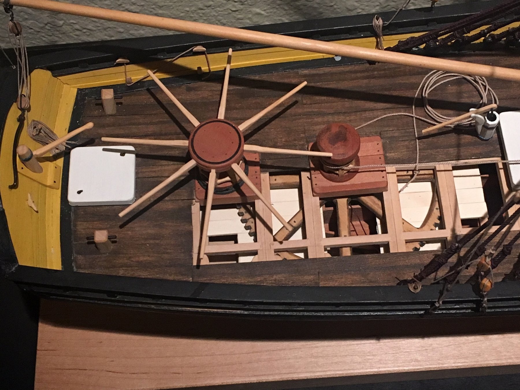
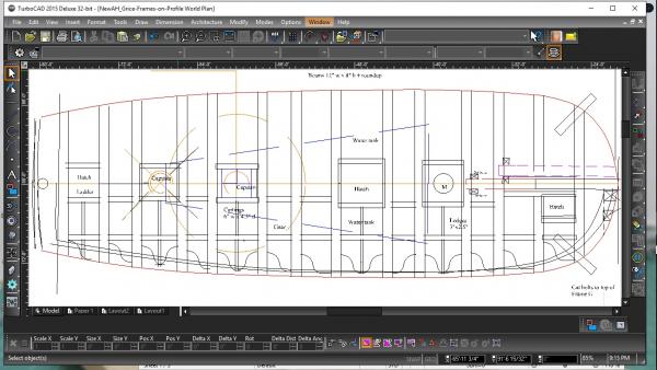
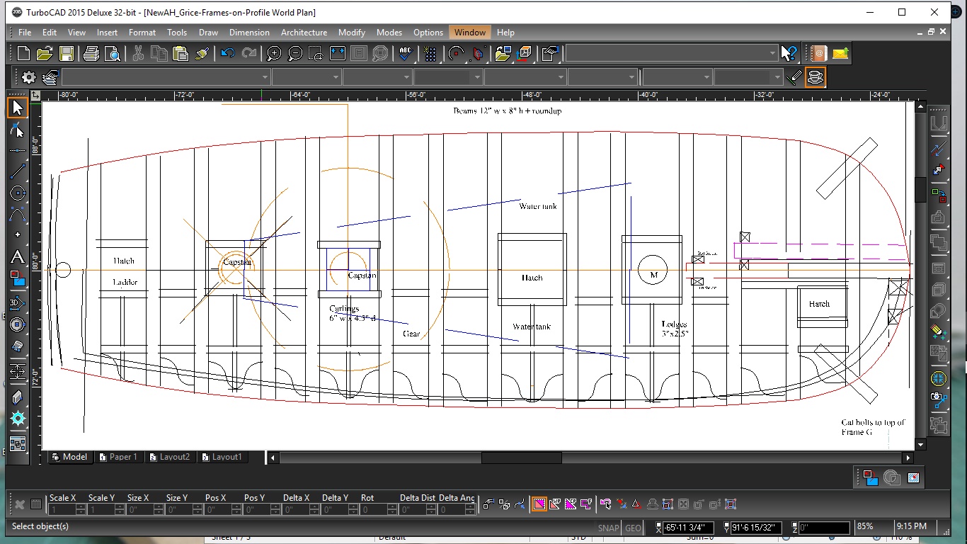
I worked on the deck plan laying out beam placement, partners, capstans, bitts, hatches, etc.
All the knees are the same profile., just mirrored. The bowsprit is removable so it doesn't get in the way of the operation of the great anchor cat. The inboard end is fastened with a pin through the bitts.
Maury
-
Druxey,
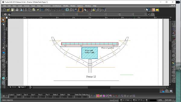
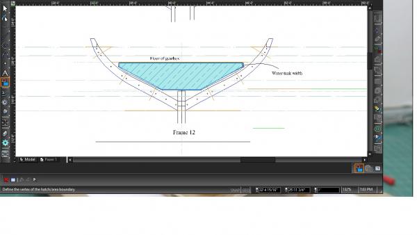
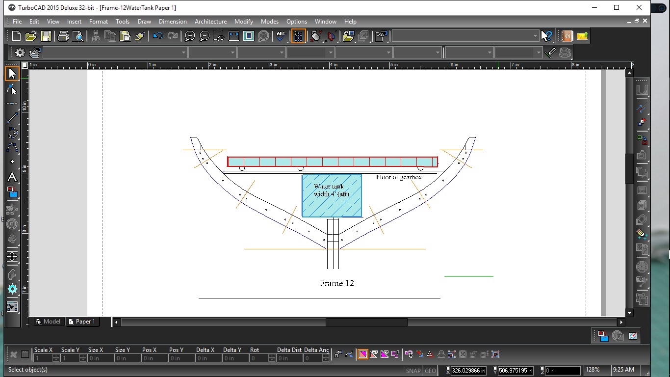
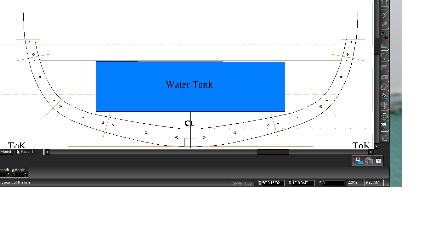
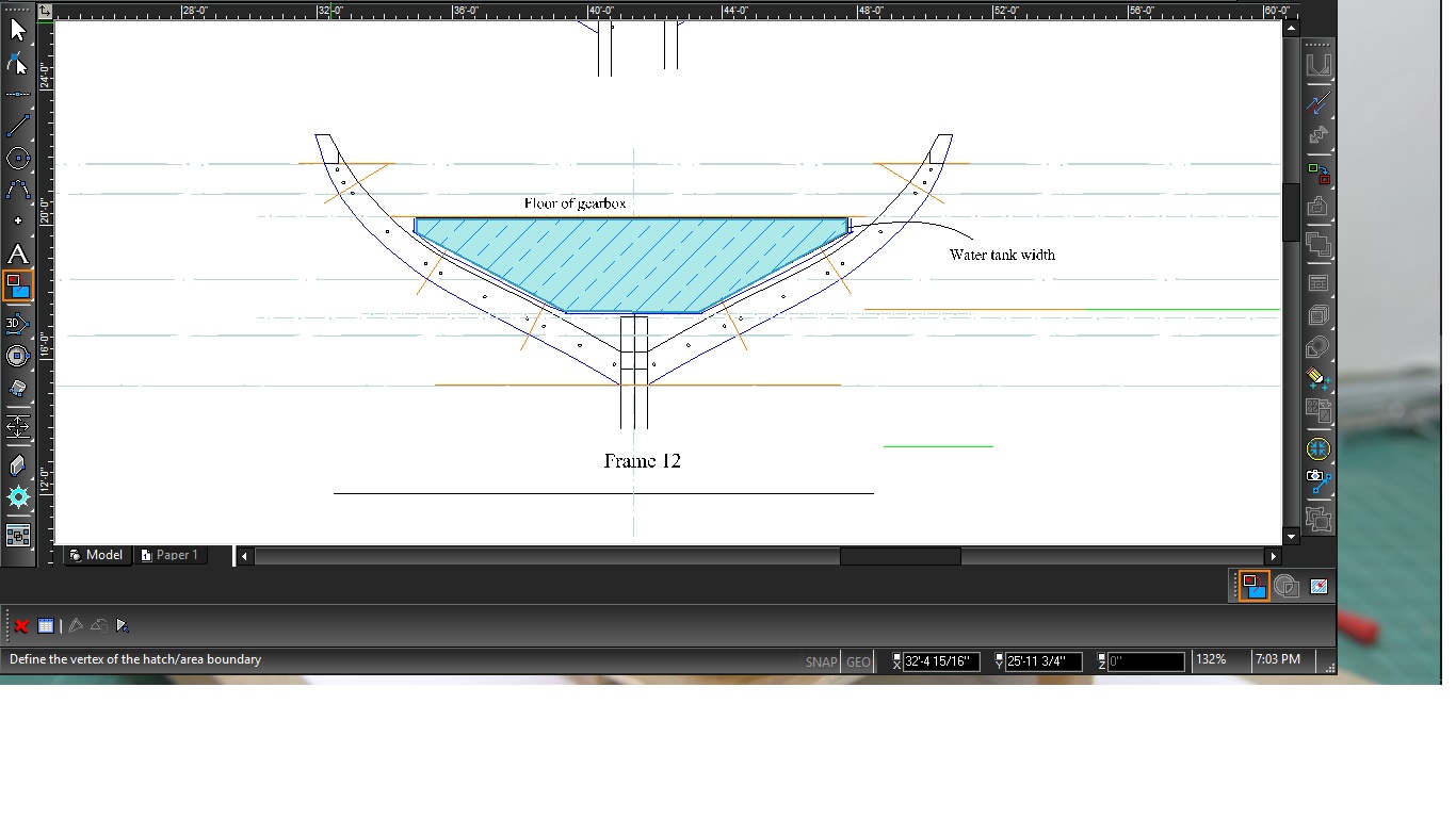
I think you are correct about the width. If I square-up the sides at the fore and aft ends, it becomes about 11.25' wide near the mast (at Fr. 00) and about 4' wide at frame 12 making it a very long isosceles trapezoid. There is a 3' square well in the middle of the tank protecting the axle and supports for the large gear that takes up a good amount of space / volume, but the Grice drawings (for what they're worth anymore) clearly show the tank going back to the aft most capstan. With this revision, most of the water would be near midships and less possibility of sloshing. Also, that construction would not use the interior planking as part of the tank, which makes sense because the planking is structural. As to the lining, zinc was widely available at the time and seems plausible. Better than lead, but they may not have understood that at the time. There is nothing in the various sources of Harbor Craft and Water Hoys that I have that indicate the linings. Probably easy to "model" as well. Thanks again for all the comments.
Maury

-
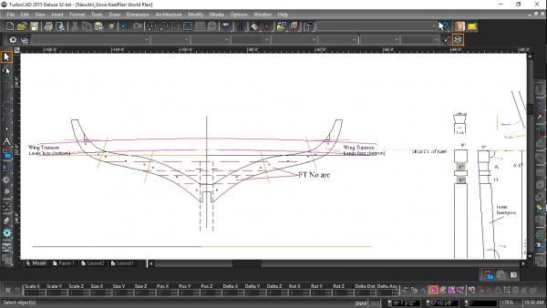
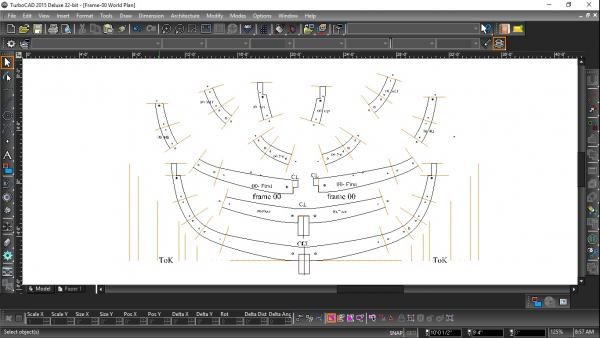
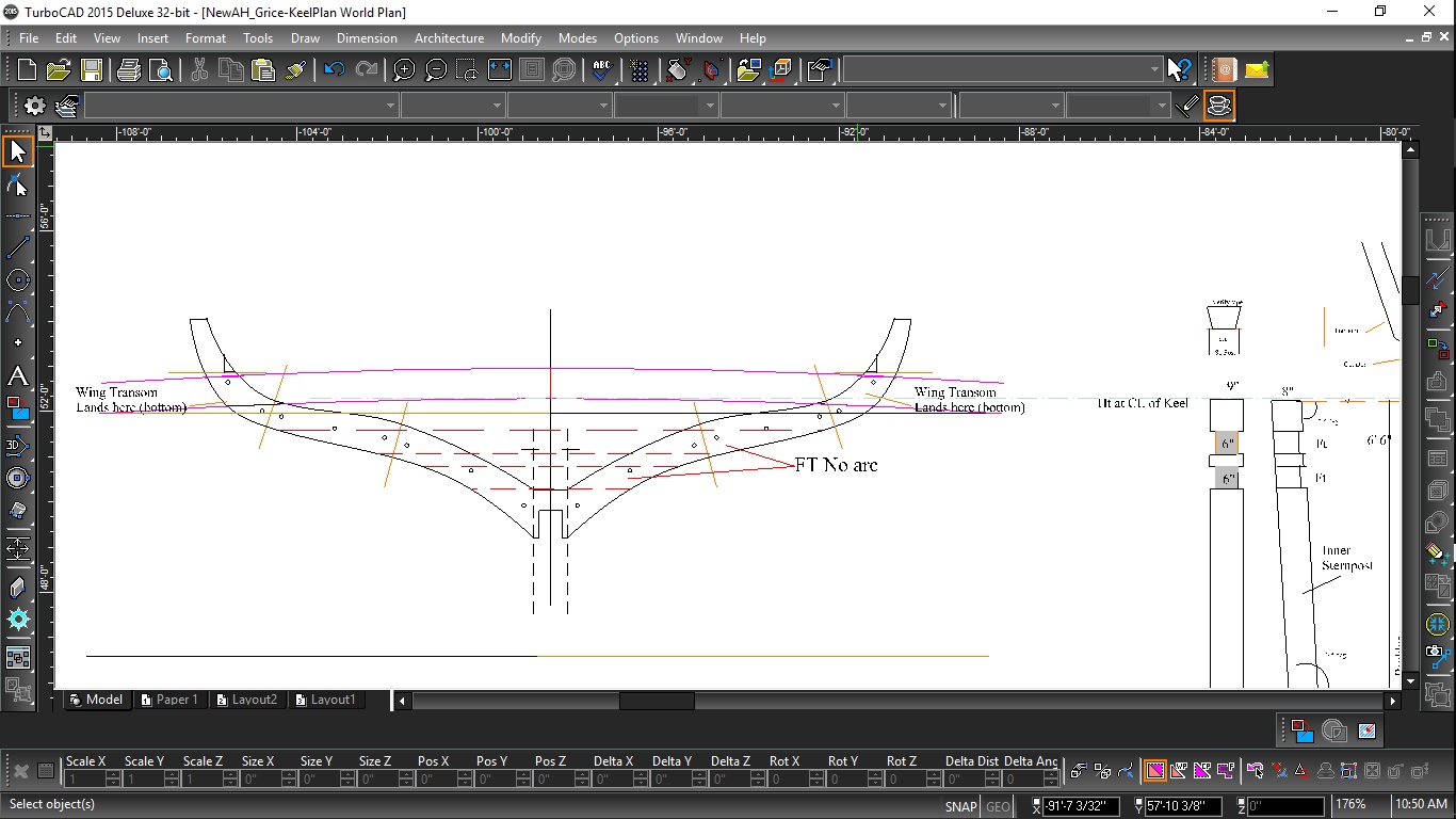
After lining up the large capstan gear on the frame plan, it was obvious the drawings by Grice were done with some artistic license. It clearly shows on the profile that the large gear is approx. 16' diameter. Problem is the inside of the frames at that location and height above the keel are about 15'. I downsized the gear to 14' (1/8th reduction) to allow for planking and re-located the capstans to fit.
Water tank: the description is clear that the water tank is 26' - 9" long (from about dead flat aft to frame 12) but nothing about the width. The height is limited by the cabinet that protects the gears. The inside frame sizes are the limitation. See the pic. below as a possible shape. That size is about 500+ cubic ft. or approx. 3,750 - 4,000 gallons. Anyone have a better idea? Narrower? As far as the floor and walls of the tank go, I assume they are caulked wood planking. Could there have been a metal lining? Since it might have been drinking water (?), I doubt it was tar coated, but who knows.
Maury
-
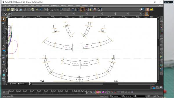
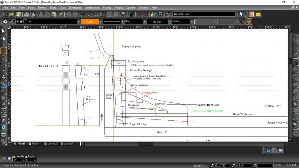
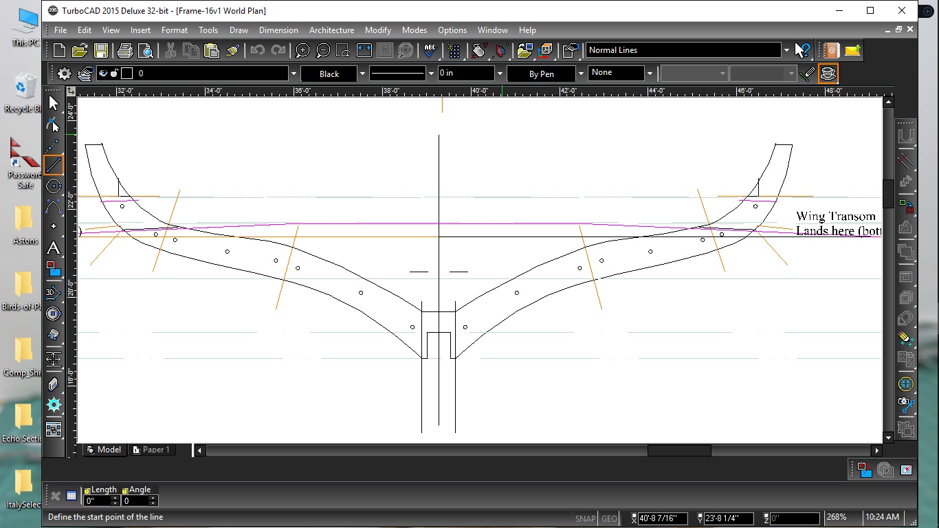
Re-doing the tops, I realized I need to correlate the levels of the filler transoms on the keel plan with frame 16. Involved moving the FTs around a bit to fit to the frame. While the Wing transom is arched, there is no need to do so on the fillers. Everything's connected...
Maury
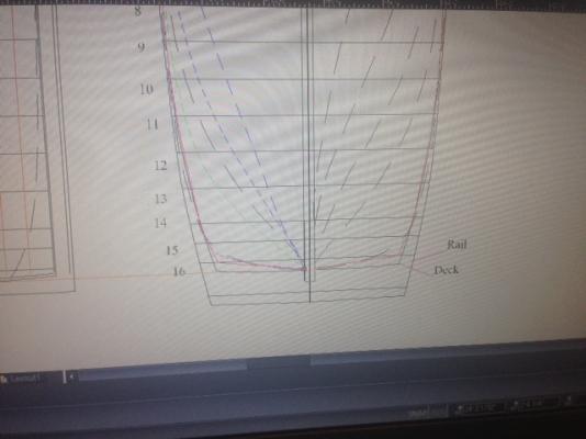
-
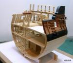
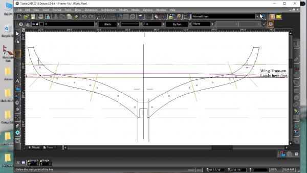
Thanks for the guidance. I was going to go back and re-do the top timbers. This exercise is certainly giving be a better idea of the construction process. Attached is a recent pic. of the aft-most frame. I inserted the arc of the wing transom (magenta line) and it lines up where it should. Back to the frame plans to work on the little tops. I had no other pressing things to do this weekend anyhow.
Maury
-
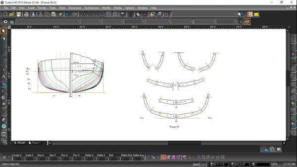
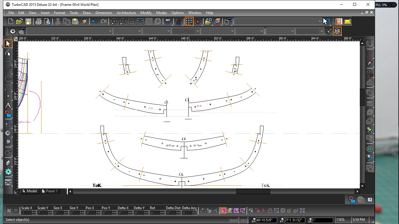
Lots of time lofting frames over the last week. Very repetitive. Plenty of goofs and re-dos along the way.
Each frame will be printed (3x) on 8 1/2 x 11 sheet. I've completed lofting all but the fore-most and aft 2. Slightly different sequence for the half-frames. I'm not sure I'm going to cant the front two and aft one. We'll see.
Thanks again for all the comments and help with the size and positions of the futtocks.
Maury
-
-
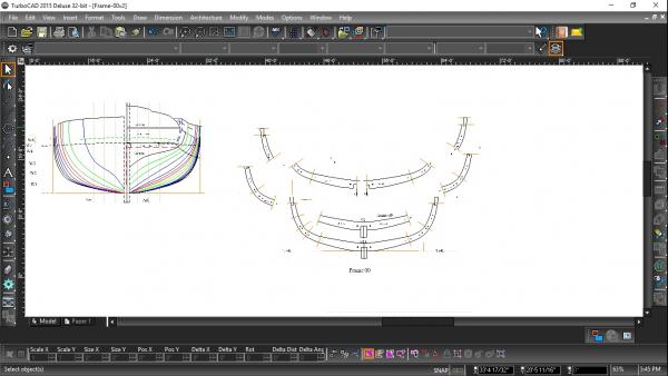
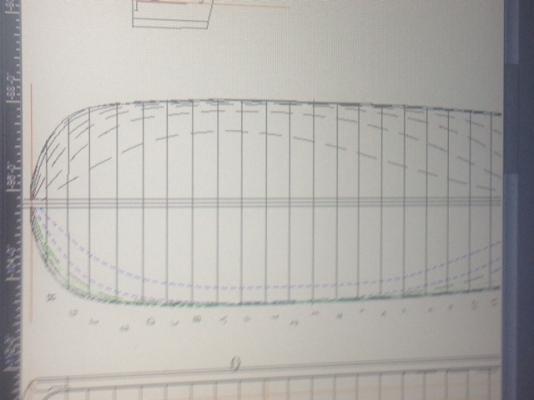
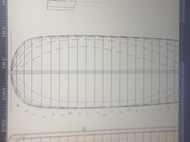
The Futtock Lines on the body plan are drawn across both sides and "look fair". You should be able to click on the picture to enlarge. The lines appear as purple so they don't get confused with other lines. Next I'll move fore and aft repeating the lofting process for each frame, checking the starting points by referring back to the body plan. Once erected the "line" of all the futtock joints on the frames should appear as a nice faired image.
Maury
-
Thanks again for all the input and the "likes". One more attempt for review. I've shortened the floors and first futtocks a bit and lengthened the other pieces and it seems to make more sense. Once satisfied with the general proportions, I can then lay out new futtock lines on the body plan and proceed to the remaining square frames. One step at a time. On subsequent frames (every other one) the top extends about 20" higher to support bulwarks and the top rails.
Maury
- AnobiumPunctatum, mtaylor, Canute and 1 other
-
 4
4
-
-
Second try with fewer futtocks per druxey's suggestion...better and certainly easier.
Maury
- JerryGreening, tlevine, dvm27 and 6 others
-
9
-
-
-
Thanks again for the comments and all the "likes". I started on the frame lofting to get a sense of the procedures. Instructions were followed from Lofting Ship Plans, aided by the comments in Ed Tosti's Young America vol. I using a pin alignment system. A few mistakes and lessons learned along the way in dealing with the parts of the frames. A point here is that once the parts are separated, you can't fix something on a futtock-- like pin alignment. You have to discard the part, fix the item on the full frame and take it apart again. I'm not going to loft the beveled frame sides at this stage. Most of the frames are very close to DF until you get to the foremost and aft most frames. The dead flat frame and parts seem finished. If anyone notices a fatal flaw along the way, please "speak now or ....."
Maury
- Canute, JerryGreening, vaddoc and 2 others
-
5
-
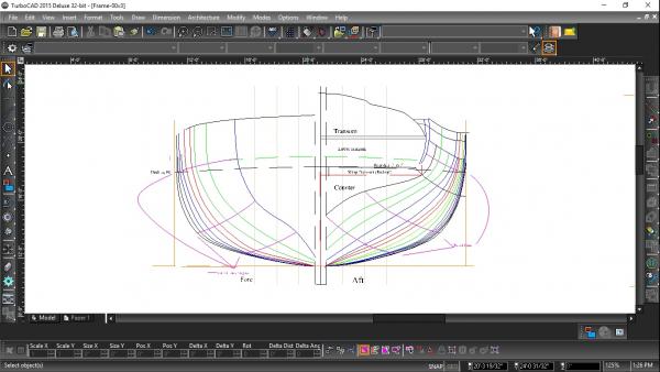
A lot of back and forth regarding the height of the wing transom (and hence top of the inner stern post). There is nothing definite I can find so with the helpful comments of a few and some more research, I've decided to place it with the bottom just below the transition from counter to transom. That's where the fore & aft planking changes to athwartship on the counter so it will provide support in three planes.
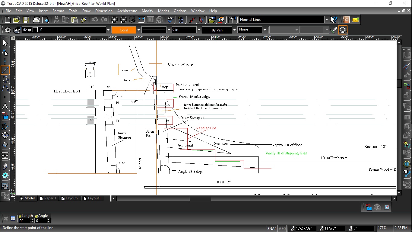
The keel is 12" tall, the rising wood another 12" and the Keelson will be 12". Frames are 6" (paired to make them 12" sided). When I get tired of doing the computer work, I've gone into the shop and built some mini clamps (per Ed Tosti's plans). Second Mate thinks they're "cute".
Maury
-
-
I spent many hours working with TurboCAD transferring, projecting and cleaning up the lines. They look pretty good. I have saved a separate copy of just the keel plan and the problem I'm having is determining at what height the Wing transom should be. My best guess is at the top of the deck beam level, and resting on top of the inner sternpost. Any thoughts? Thanks,
Maury
-
-
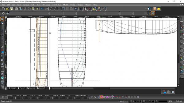
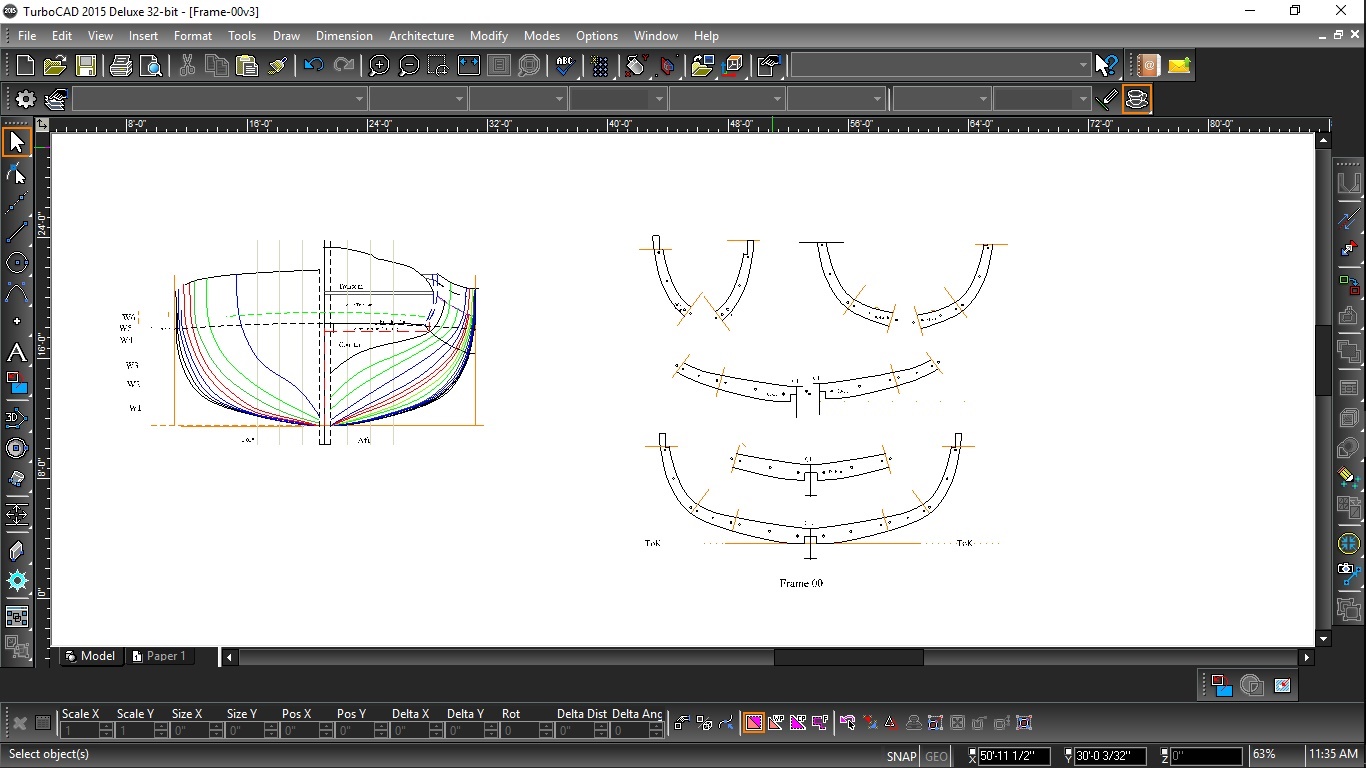
I think I found my misteps. The halfbreadth was erased and started again. I tried to work backwards from the traced lines on the right side with vertical construction lines up to the body plan to see where the WLs began and ended. This time, on the halfbreadth, I started the lowest aft waterline from a point projected from the bearding line on the (vertical) profile. While the new lofted WL (on the left) is a bit wider than the traced line (on the right) amidships, the line does blend into the deadwood smoothly.
Thanks for the comments and tips.
Maury
-
Druxey, The smooth blend to the deadwood was what I was hoping for. Instructions say to start where the horiz. Construction line from the profile rabbet lines up on the half breadth and then connect the dots as you move from one waterline / station line / intersection to the next. Clearly I'm doing something wrong in the aft area. Wayne, the body plan matches the original scaled and leveled picture (traced line for line). I've done a screen grab and got a cleaner but smaller picture. Maybe it should start where the half frame intersects the deadwood rather than the rabbet. More playing with it tonight.
Thanks for all the comments.
Maury
-
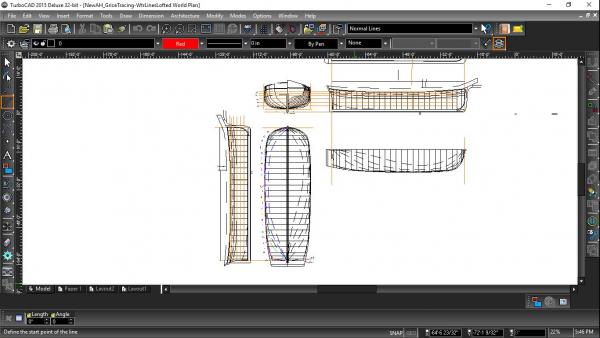
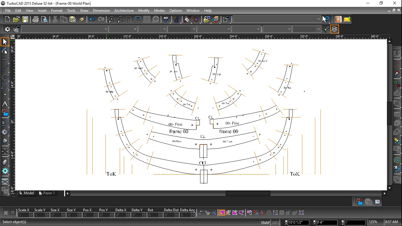
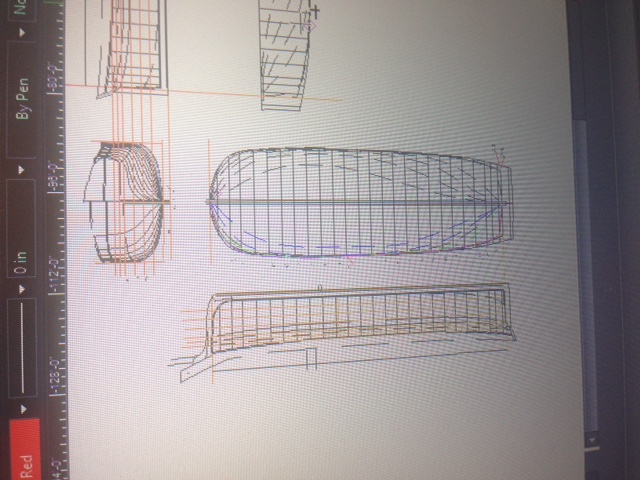
Thanks for the input and help. The stern post is off-set by about 3.5 degrees. The body and all three plans attached. Sorry about the orientation on the first one. Construction lines were run from body water line / section intersections to the half breadth station lines and those intersections were plotted. Everything is square and aligned...distortion from camera.
Maury

-
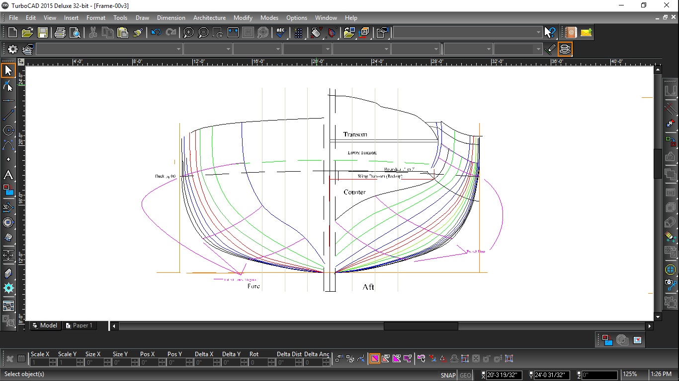
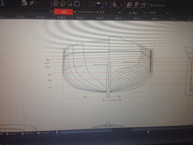
The left set fair with the station lines. No diagonals avail and I don't know how to introduce them. Could the inner most line on the right half be a buttock line? Notice how the WLs on the right (traced from old plan) meet the keel much farther forward than the ones I lofted (on the left).
M
- Canute, mtaylor, JerryGreening and 1 other
-
4
-
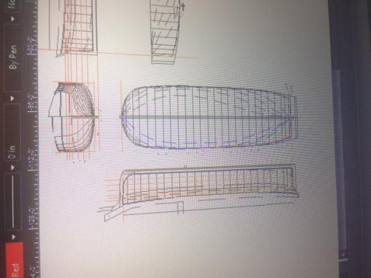
Lofting: After several practice runs the process is coming together...slowly. I'm following "Drafting Ship Plans in CAD" by Wayne Kempson (WRKempson on this forum). I've traced the original drawings by Grice as I think that is more reliable than the nice set of plans that were provided to me (in theory lofted from the same drawings). Everything has been re-scaled to "full size". The profile, body and half breadth have all been synchronized to keel and mid-lines and the process of projecting waterlines to the half breadth is underway. Pause...Look at the two halves of the plan below. The upper half shows the waterlines as traced from the plan sheet (drawn in 1997??). The lower half show the waterlines as projected from the body plan per the instructions. There is quite a divergence at the lowest (inner most) waterline. If the lofting process is to be trusted, I think I have to go with the lines I lofted and delete the traced lines. Anyone with lofting experience please feel free to comment.
Maury
- Canute, JerryGreening, hexnut and 3 others
-
6


Anchor Hoy c. 1825 by Maury S - FINISHED - 1:48 - Harbor craft - POF
in - Build logs for subjects built 1801 - 1850
Posted
Here is the revised Knee plan...much improved. Thanks Druxey.
Maury