


Gahm
-
Posts
1,217 -
Joined
-
Last visited
Content Type
Profiles
Forums
Gallery
Events
Posts posted by Gahm
-
-
Thank you, Yves!
Thomas
-
Thank you, Ferit! In hind side I probably could have saved me some work by framing the gun ports a little differently . . .
Thomas
-
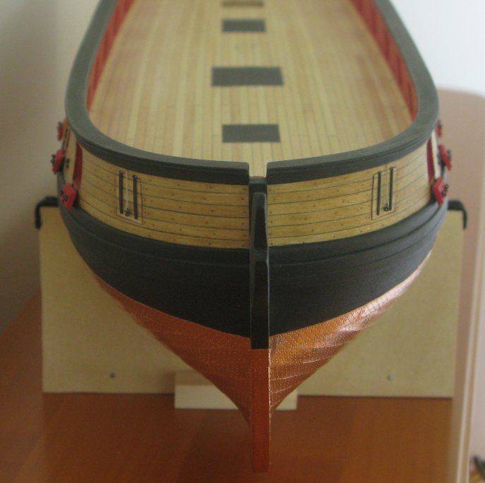
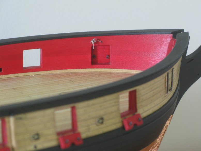
I found a few hours to finish the bridle ports and one of the rear gun ports. I hope that with coming fall and winter I can shift more time to ship modeling again . . .

The gun port lids were done following Chuck’s instructions. The photo etched hinges for the bridle ports supplied in the kit were not quite as long as they were shown on Chuck’s plans, so I made my own.
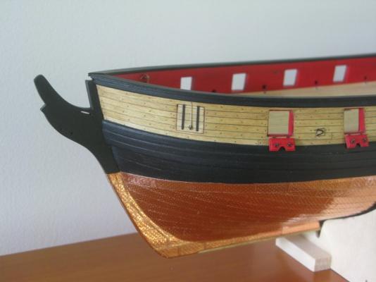
Bridle port, port side

Bridle ports, front view
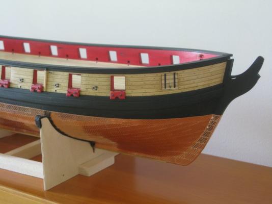
Bridle port, starboard

Bridle port, deck view
Closed rear gun port
Rear gun port, deck view
- mtaylor, Ryland Craze, rvchima and 9 others
-
 12
12
-
-
-
Thank you, Rod! When I had finished with the little ring bolts, I was quite happy that I made them. However, when I tried to produce them, it was good that my wife did not hear me because I was constantly cursing these tiny things jumping away at the slightest touch, sticking to the tweezers, and in general defying gravity completely
Thomas
- fnkershner and augie
-
2
-
-
-
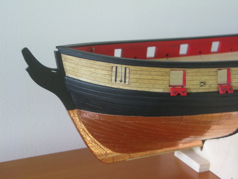
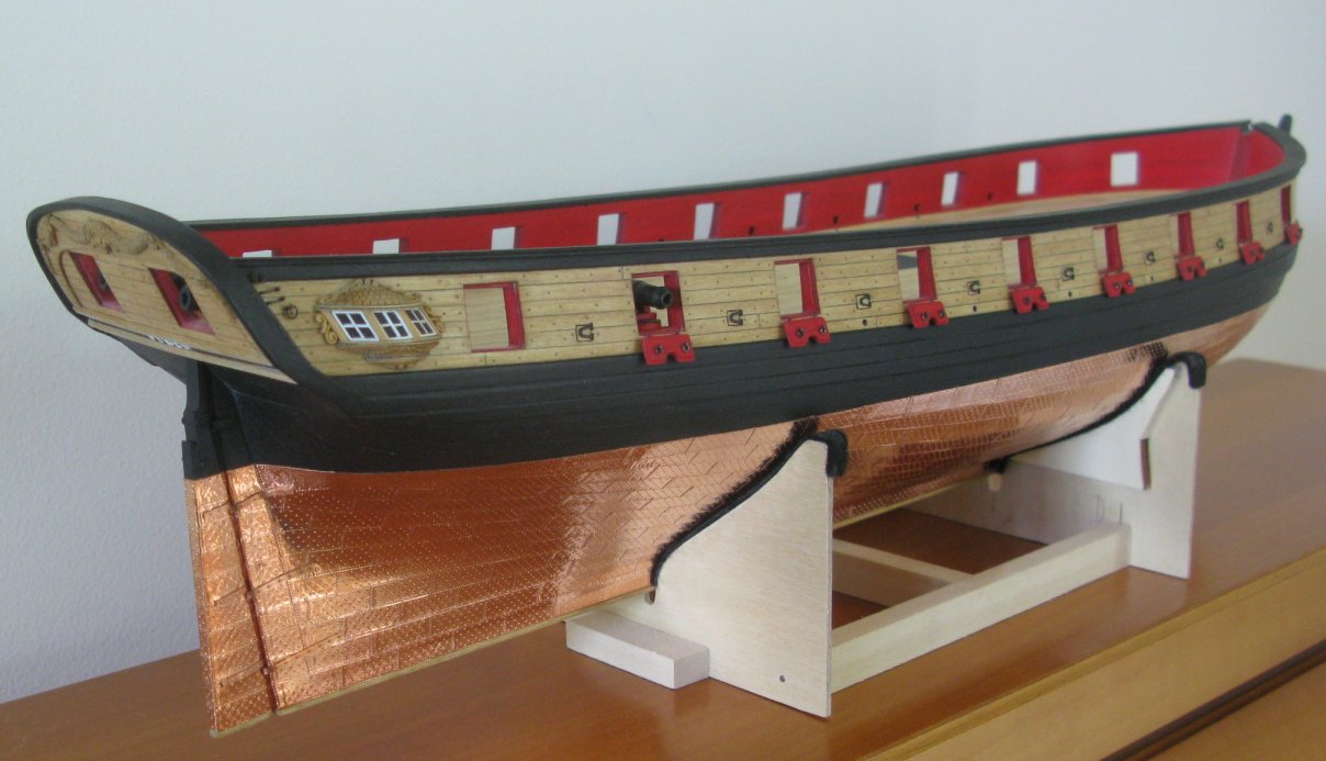
Unfortunately, during the last few weeks I had very little time for working on my Syren. Too much focus on business and competing projects with higher priorities . . .

Nevertheless, here is a little update. The lids of all open gun ports on both sides are in place, sheaves and fenders are done, and work is progressing on the bridle ports.
Thomas


-
-
-
I haven't seen your build for 2 weeks as I was on a business trip with very limited Internet access. Wonderful job on that rigging!! It looks like you are about to cross the finishing line! What comes next?
Thomas
-
I just had the time to go through your whole build the first time . . . excellent work and craftsmanship! It is a pleasure to watch it!
Thomas
-
-
-
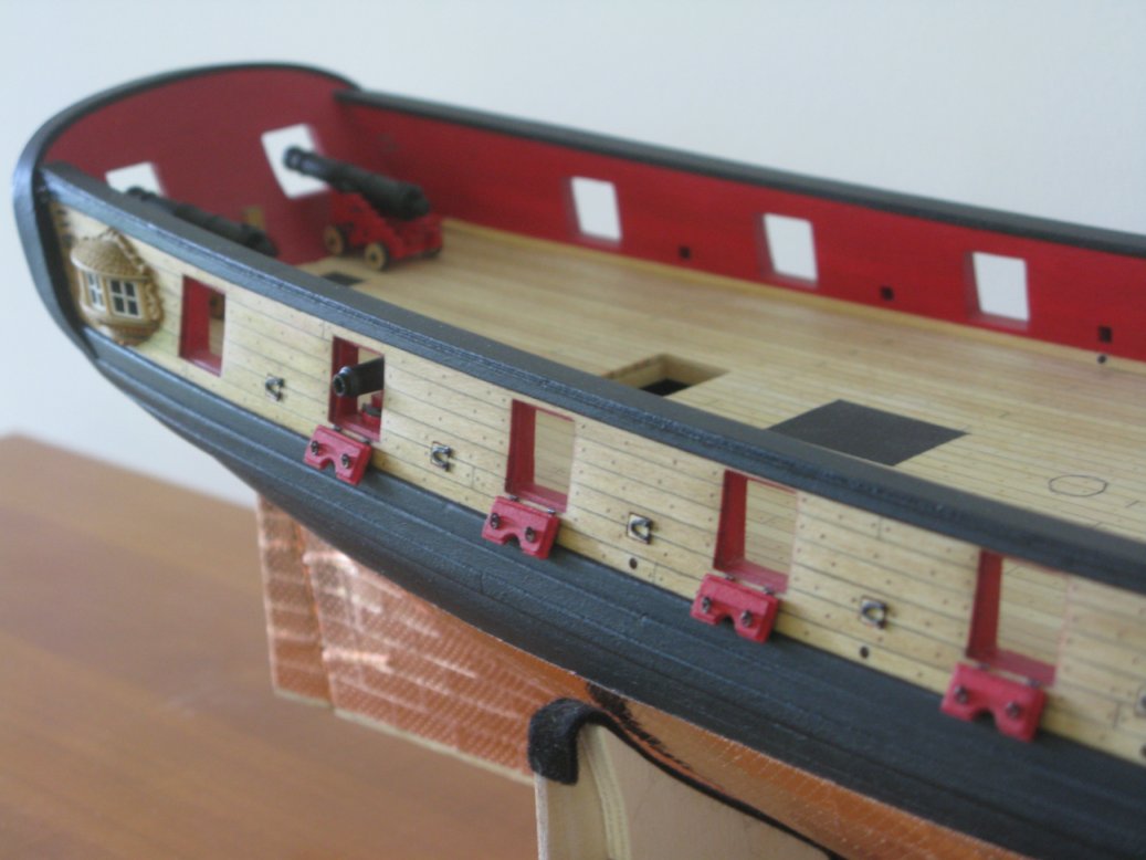
The first 8 starboard gun port lids are in place.

- foxy, Blue Ensign, augie and 6 others
-
9
-
-
Hi Dirk,
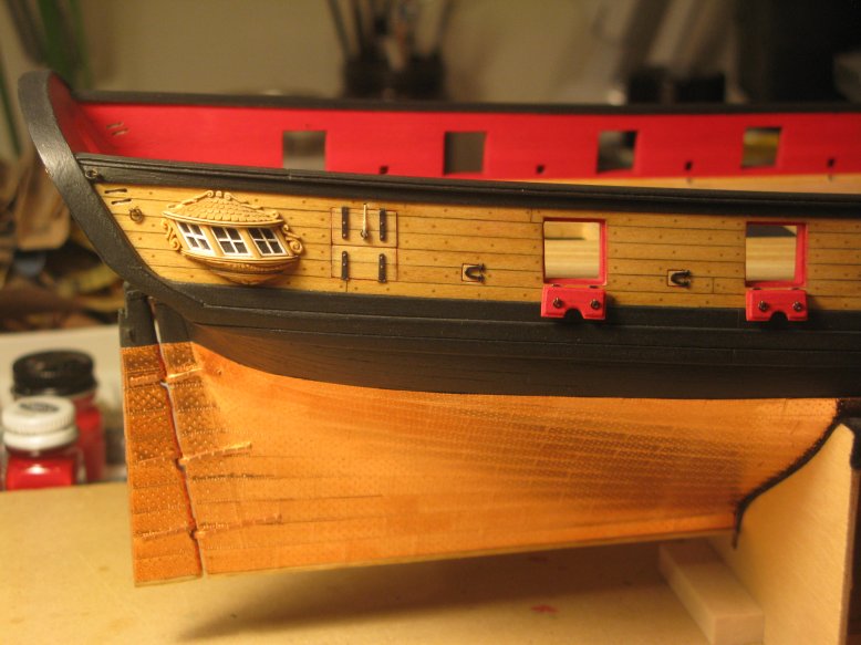
Before we had the “big crash” there were several build logs of people showing different ways of constructing the quarter galleries. They all yielded very nice results. One person carved each quarter gallery out of a piece of (box?)wood . . . it looked very nice. The most common approach was to carve the part from the bottom of the windows down, and the part from the top of the windows up, and design the windows and the pillars in the gap between these two parts. For the roof they went with individual shingles made out of birch veneer. I think Chuck may have used a similar approach for his original designs, and he may still be able to provide you with a few images. This type of technique you also find in some of the scratch build logs for the design of the quarter galleries. And then there is also the polymer clay sculpting approach, and last but not least using the metal casts from the kit, and refining/ recasting them. So there are a lot of possibilities . . .
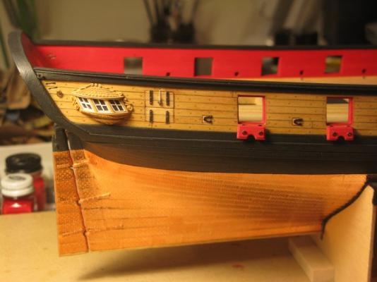
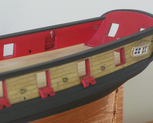
Where my method is concerned I don’t really have a lot more images than what I published in my log already. I basically broke down the whole task into a lot of little steps which could be individually refined. I started with the 3 moldings. The width I got from the plan, the depth and general shape I extracted from the metal castings. Each molding was built from 2 pieces of bass wood sanded down to the correct thickness (see plan). I rounded the edges and glued them together with a little piece of black paper in between for better contrast. You cans see one of the finished moldings in image 2 (1st page of my build log), upper right corner, a second one already mounted on the window wood block in the middle of image 2. The individual windows and the wood block to mount the windows came next. The window frames were made from thin strips of birch veneer painted white, the window panes out of bass wood, thinned down and painted black. I assembled the windows out of little parts as shown in image 1. The wood block is a bit tricky because you must get a lot of angles right. Especially don’t forget that the whole assembly is not perpendicular to the ship’s wall but angled by about 75 – 80 degrees, which makes things even more interesting. The next step then is to glue the upper molding to the wood block, mount the 3 windows, design the pillars in between (I did mine out of pear wood) and finish off the assembly with the lower molding (images 3 and 4). All that remained to do then was to make the two filler pieces below the window assembly, the top part and the side ornaments. All of those I made out of pear wood. The 2 lower pieces were cut in shape using an Exacto knife. When doing that you obviously have to leave enough wood so once you carve the ornaments you end up with the right dimensions. The carving of the ornaments was done with the Exacto knife, some micro chisels, and for the coarse work a rotary tool. It took me several attempts to get these right, but once satisfied I glued them together and ended up with the result shown in image 5. The top part of the quarter gallery consists of the backplane with some ornaments and the shingle block. The backplane I cut out of pear wood sanded down to about 1mm thickness. The shape of it I extracted from the plan. The ornaments were made using the same tools as before. Finally the backplane was sanded down again until the thickness appeared right for the scale (~ 0.75mm . . . see image 8). The shingle block was cut in shape with an Exacto knife and the shingle layers cut into it with the rotary tool (image 7). All that remained to get the final shingles were some vertical cuts and rounding off of the corners (image 9). To finish off the quarter gallery the shingle block needed to be glued in place and the side ornaments had to be made (image 6). For most of these pieces it took me several attempts to come up with an acceptable result. So patience and time are important ingredients in this process.
I hope this description helped a little to explain how I made these quarter galleries. Good luck with it!
Thomas
-
Eric, I think the trick here is not so much which rotary tool but that you use a fine diamond bur with the tool. I have a Proxxon with a flexible shaft. The flex shaft just allows for more precise motion control. And only separate the hinges from their photo etch grid once you are done with the thinning task. It makes for much easier work that way because you have a nice handle!
Thomas
-
-
-
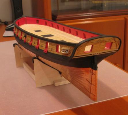
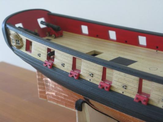
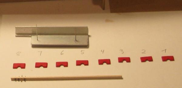
I started with the lids for the sweep and gun ports (still chapter 9 . . . I have the feeling I am stuck for ever in this chapter
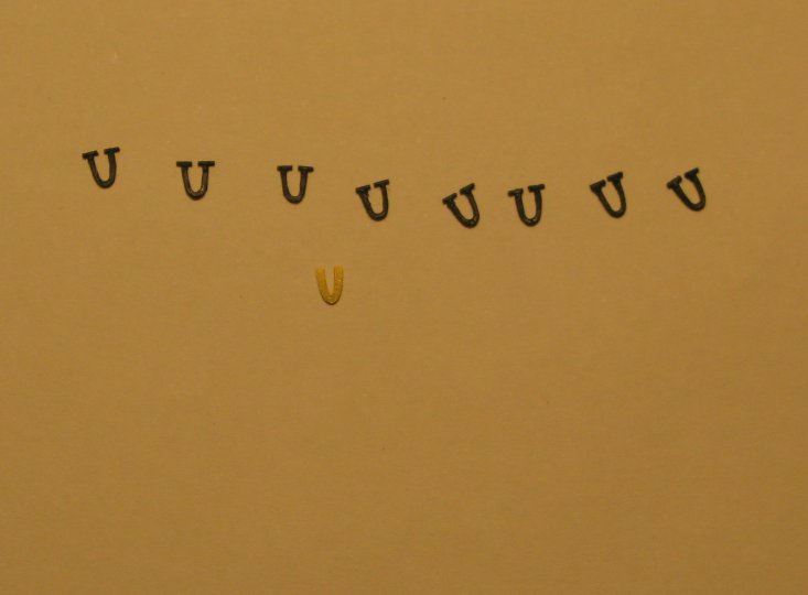
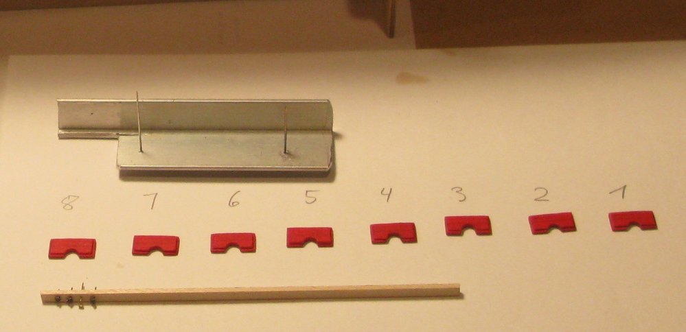
). In comparison to the plans the photo etched horse shoe hinges for the sweep port lids seemed a bit too thick and too triangular shaped . . . so I thinned them out and got the shape “more horse shoe like”.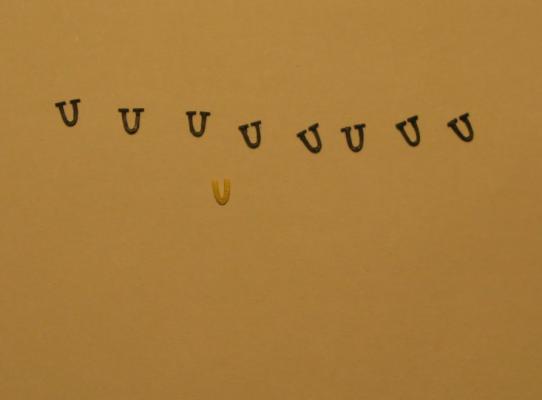
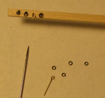
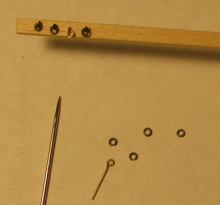
I also experimented with changing the eye-bolt simulation on the gun ports to the real thing. The trick here obviously is to stay within scale and not to end up with rings which are too large. But I think my first prototypes (3 black eye-bolt ring combinations mounted on the little wood stick as compared to the not painted brass eye-bolt simulation) got close enough.
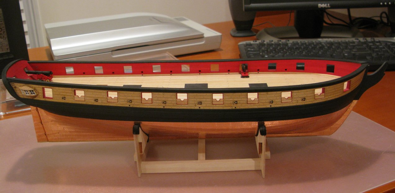
The next 2 images show my first set of gun port lids and how they (test) fit into the gun ports as well as the finished and mounted sweep port lids. As it is the case with most of the Syren models I also will finally mount the gun port lids in the open position.

-
-
Excellent work, Augie! Your Syren looks very good!
Thomas


US Brig Syren by rvchima - FINISHED - Model Shipways
in - Kit build logs for subjects built from 1801 - 1850
Posted
Just saw that you crossed the finishing line. Congratulations!! Your Syren turned out very nicely!
Thomas