HOLIDAY DONATION DRIVE - SUPPORT MSW - DO YOUR PART TO KEEP THIS GREAT FORUM GOING! (Only 24 donations so far out of 49,000 members - C'mon guys!)
×


Senior ole salt
-
Posts
393 -
Joined
-
Last visited
Content Type
Profiles
Forums
Gallery
Events
Everything posted by Senior ole salt
-
 Yea , soon we'll all need l magnifying glasses to see your work. Amazing. Do ya ever have any shortage of material to transform ? SOS
- 64 replies
-
- 4
-

-
- koch
- polar ship
- (and 2 more)
-
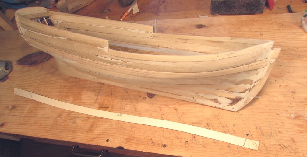
Add to Post The Providence plan calls for a wale P&S showing 2' wide the full length of the hull. To determine it's shape I pinned on a "fairing batten' "1/16" X 1/16" " in the designated area. A tweek here and there was needed to get it to look "fair". As much as a 32 of an inch made a difference in achieving a "fair" look . Once satisfied I traced this curve on to the hull using a lead pencil. Now using tracing paper on the penciled line I captured this S curve on a piece of tracing paper which was used to transfer once more on to artists WC paper. This is in the fore ground of the image. I made it ½" wide as shown and placed it on the hull to get the stern and bow cuts. I figured if I cut this shape on a suitable piece of bass wood it would be near impossible (for me)to connect it to the hull using clamps, pins whatever. So , why not in several narrow strakes reasoning that in full size it would also impossible etc. So I borrowed stock intended for the deck which came prescribed to simulate the calking. This worked out OK for me and in the image are three of the 4 strakes to obtain the wale shape on the hull. I'm still figuring if I should apply a filler or just let the black paint do it's thing. I still haven't applied any sanding sealer to the hull. S.O.S

-
Nice job Bob. All ya need now are a suit of sails a bit of lead and a nice pond to sail her in. SOS
- 127 replies
-
- 4
-
-
- dragon class
- yacht
- (and 1 more)
-
I find myself and some work on my present build. taking the hull on my lap or between my legs to hold the hull in place during some application. Any body else do the same ? Or shouldI see my shrink ? BTW I do have various vises. SOS
-
Another word for scuppers. Notes on the plan call for them to be 3" high X 36" long to be between frames on the main deck in the region of what could be call "the waist". SOS
-
Thanks, M Taylor for the advise for a trail cutting. Shown in the image is a cutting of a gun port on a scrap bulkhead. I did use the carbide burr chucked in a Dremel for the initial start then carefully moved to the prescribed cut as related before. I finished up with a 3 cornered file and emery board. I decided not to cut the ports now but rather later as the hull needs much handling to glue the whale, channels, moldings bow to stern and rail caps. Along with the gun ports and freeing ports in the whole main deck I feel the bulwarks P&S will be rather weak. SOS
-
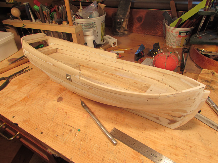
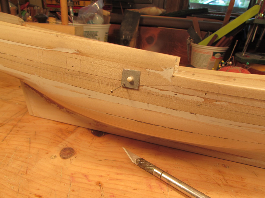
I've gotten to the stage I'd like to apply a coat of sanding sealer to the model. But I'll be darned if I want to pluck down 17 bucks for a 1qt can of commercial grade of "Sanding Sealer and use only an oz.. I hear tell one can make your own using talcum powder . I'd like to try that but use some of the cans show above. Can anyone here tell me the right proportions ? And just how good is this home made solution ? Thanks. Shown in the images s my lay out for cutting the gun ports. I established their location from the plans and the station marks on the model. I drilled through from the inside of the hull at the center of the proposed cut. I used a thin metal template with a hole drilled through then mounted on the hull in the exact location secured with the pin as shown. Now I can mark with an Xacto knife for the start of the cut. After the initial cut I'm thinking of plunging right into the center with a carbide burr then trim out to the xacto knofe of a small saw made from an old Xacto fine saw blade. Thanks to those who peek in here. SOS


-
My plans are a bit different. Only swivel guns on the Poop. Also the across ship bulkhead under the Poop D. shows an angled off set instead of the curved sweep, your plans show. 20th century architects had to deal with collision bulkheads etc. The great cabin layout has the furniture is arranged differently. BTW How does one explain "Poop deck" to non marine types ? SOS
-
Hi Chuck, good to see you starting your log build. I got some deck plans that you might not have and would be glad to get a copy out to you. ( I Obtained them from a former skipper of the replica) Thanks for posting the history of the ship that hasn't gotten much attention from the public and especially kit builders. Maybe we can get them off their collective duffs and come out with one!! SOS
-
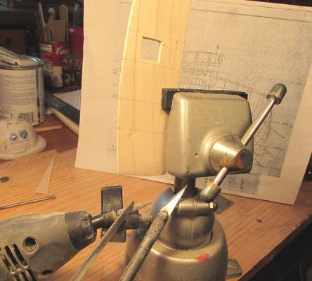
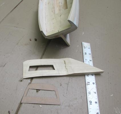
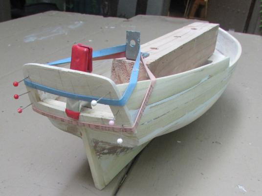
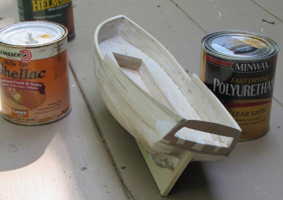
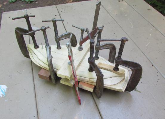
Still making progress. The transom has been carved to the curve shown on the plan ( or there abouts) I carved it using a cardboard template as a guide. (see image.) Notice in the image I first cut out for the window, before any shaping was done. The transom is carved from a scrap and provided a "handle". ( It could have been longer) This for me makes the process easier. I used gouges , rasps chisels and lots of sanding. Trial fits were frequent as well as working towards the desired thickness. The template allows me to re-establish the transom outline after sanding or whitling. After getting reasonably close to the desired shape I pinned it on the stern to get an idea how it all looked. Glueing it on the stern resulted some "rubber band clamping anchored by my "vise block", as well as a conventional clamp. After the glue sets up, I'll do some more shaping, filling and trimming as I deliberately made the whole thing a bit bigger. Next comes the windows and inside "glass." SOS
-
Tom , Yes this style of ship modeling is labor intensive but supplies much kindling for next winters fireplace, However most of that sort of labor is over for now , at least with this model. Hope you poke in often. Chuck I haven't gotten my "fly swatter" decking yet but probably will try to work with it. . I will take your suggestion about the Minwax sealer, thanks. It will be neet to watch your progress on the other "Providence" thread. You seem to be ahead but this isn't a race. Right now I'm working on the transom which will be carved with a built in curve. I considered bending in a thin slab with the grain up and down but thought it might change with high humidity SOS
-
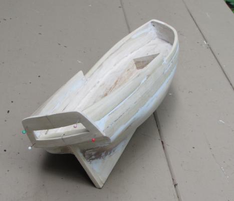
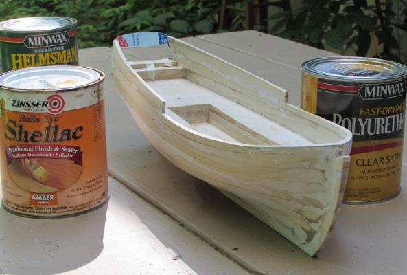
Still making progress with my lift method of the Sloop Providence. My idea of shaping the hull using a vise block worked out OK. It's removable and capable of adding to as needed when sanding the bottom. So far only 60 grit paper has been used. I intend to use successive finer grits before applying a sealer. Shown in the image is three cans of what I have laying around. I'm kind of favoring the Helmsman varnish diluted but maybe the shellac would be better. I got a lot more to do and am starting to order from a supplier made items like the decking. On the way is scribbed decking but it has no simulated caulking. Shown in one image is a template for the stern transom. ( pardon the cereal cardboard ) A couple of questions if I may: 1.. Will a coat of sealer and then a wash simulate a caulking, or seal out the wash ? 2 Should I apply the sealer to the hull before glueing in sheer mouldings channels etc. and the items like rail frames ? 3. Should I thin out the shellac before using it to seal the wood Thanks for any replies and interest. PS BTW the varnish shown in the background is a marine grade. I use it on one pirogue I paddle around. S.O.S.
-
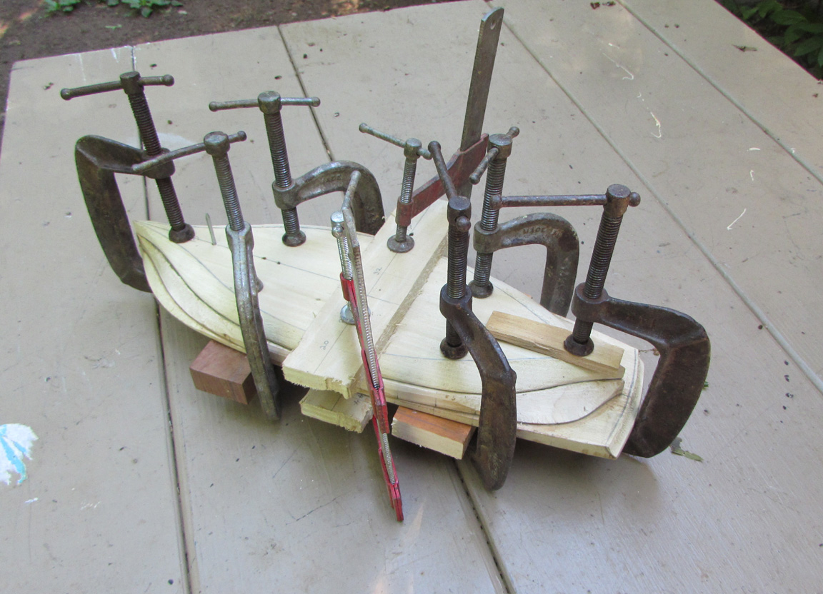
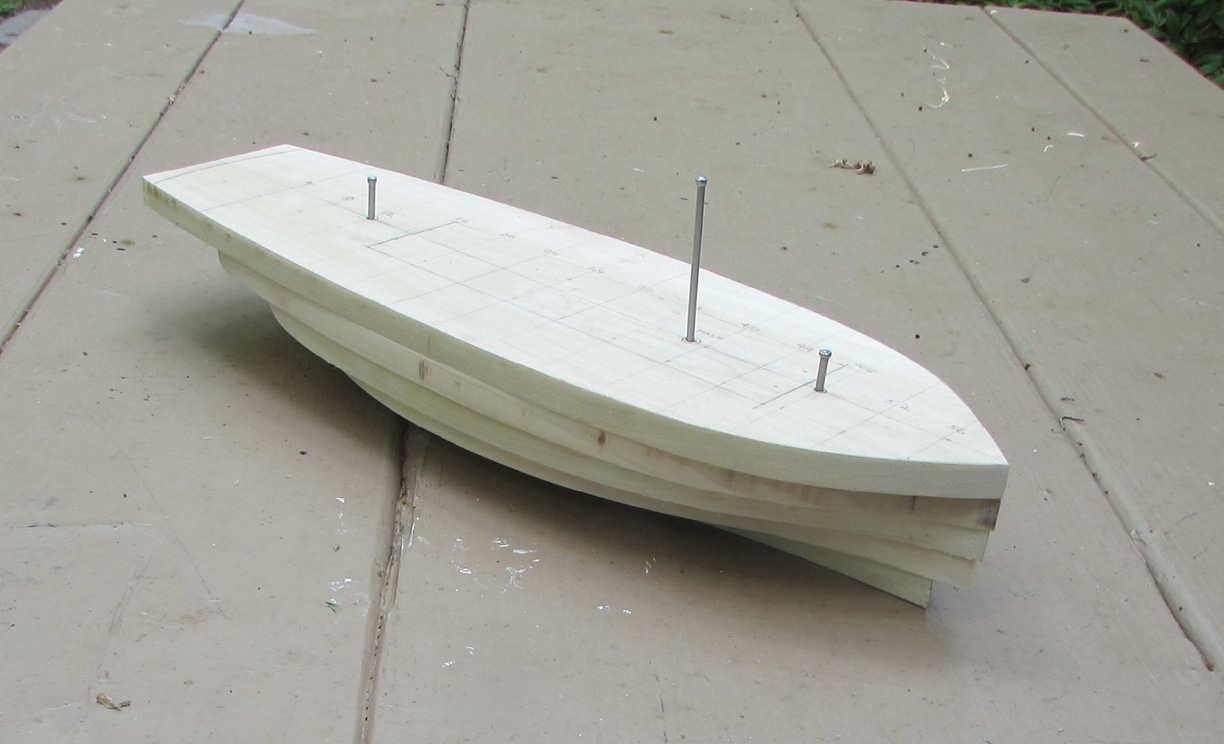
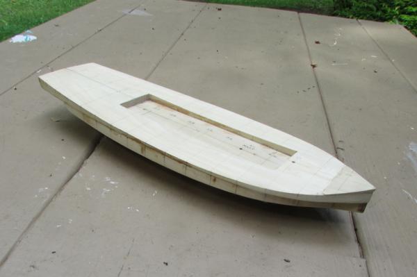
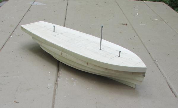
Making slow progress on my Providence as sailing my sprit rigged sharpie has more attention. However here are some images: The cut out for the vise block . This cut out has two purposes a. the vise block( to make the carving the hull easier) and b.a kind of "look " to a limited section below the hatches which will be open or at least showing the grate and ladders to the lower deck. Planking will cover most of this cut out which will have short deck beams to support the deck planking. (Vise block screw holes not showing but this method of attachment makes the vise block easily removable when needed.) The deck sheer has been cut out along with the camber of the main deck. Three lifts glued and clamped up all kept in perfect alignment with the nails as shown. S.O.S.

-
You know that one can actually shoot one of those cannons.Years ago my son and I loaded up a model 24 brass cannon with old fashioned white match heads. Rammed down a section of a 1/4" dowel. pointed it away of course. Than poked a red hot needle down the touch hole.Well that dowel went into a plastered wall. My wife and daughter soon put an end to that. Inside the house of course. but out side ....stand clear S.O.S
-
Absolutely fabulous work. I'm always astounded by the skill and workmanship exhibited on this forum. It makes me humbled and inspired at the same time. SOS
-
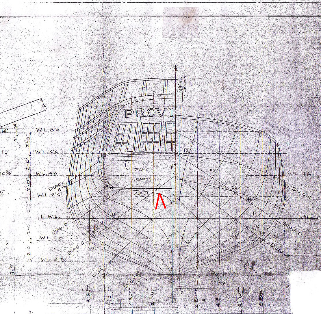
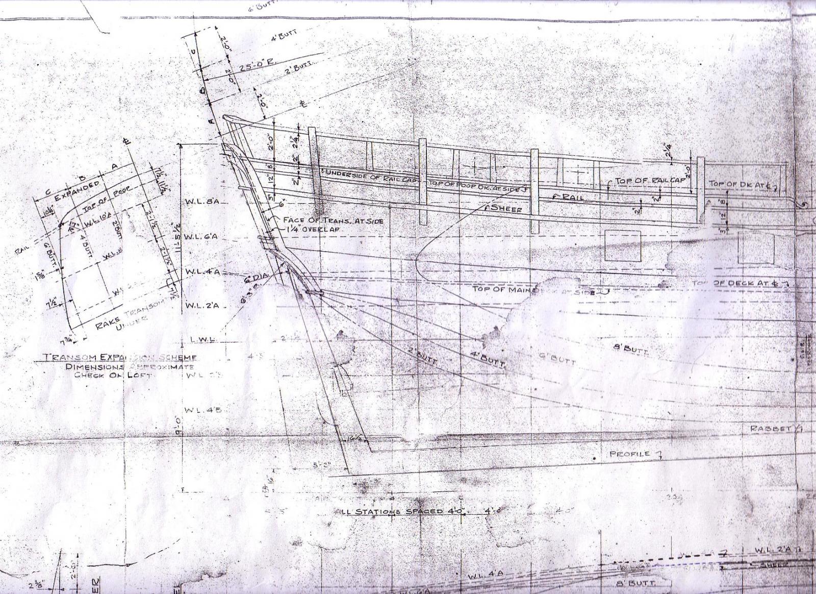
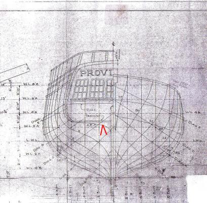
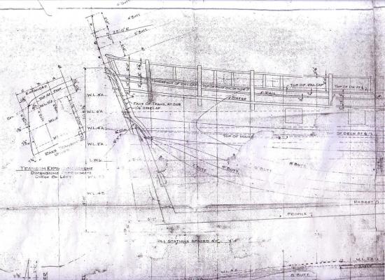
There are some things on the plan that are unclear to me . For instance the "AP" as indicated by the red arrow,as shown on the attachment . I cannot find it's designation on the profile plan shown to the right. Any guesses as to it's meaning ? Right now I'm only building up to the top of WL 4 A and intend to build the fwd. bulwarks and poop deck separately. Keel, cut water and stern post to be added later as well. Thanks SOS
-
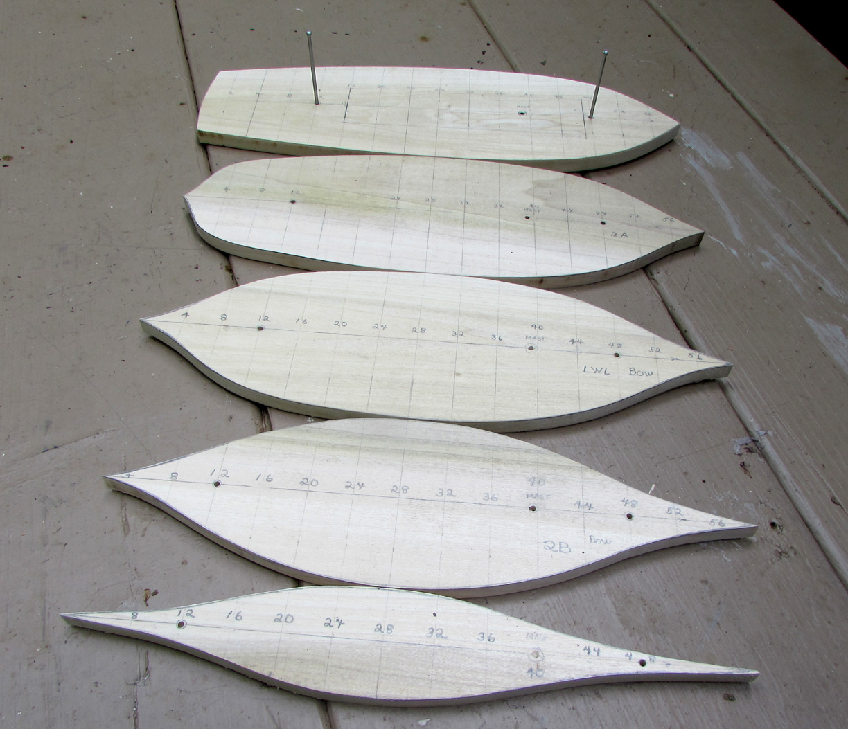
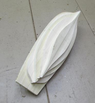
Making slow progress on my Sloop Providence as the lines are hard to see and some guess work is involved. However here are some images showing some headway. shows the lifts cut out for the vessel from the deck to the lowest lift There are 5 in all.( from the deck down ) I used tracing to copy the lines from the plan. The top lift 4a will have to be re cut for the main deck sheer. At this time none of the lifts been glued together. My idea of keeping the whole thing in register is working as the finish nails shown are inserted into pre drilled 1/8" holes. Add to Post Add to Post ( At this point the counter curve was not cut yet. and the center nail is the pilot for the mast.) I'm thinking not to glue anything yet and to attach a "Vise block " which will be screwed into each lift . This will allow some pre cutting when the Vise block is clamped into a vise allowing each lift to be worked being carefully not to cut into the outlined lines on both side of each lift. The top lift will have the this "Vise block" screwed to the under side of the lift so that the sheer can be cut to shape. I made a template for this taken from the plan. as well as a template for each lift as well. I'm also thinking of glueijng one lift at a time with the "vise block" and work the concave hollows with a gouge but not all the way. This will be done when the whole thing is glued together using 80 grit sand paper working up to 220 in stages, all wrapped in a suitable curved pre curved wood blank. S.O.S.

-
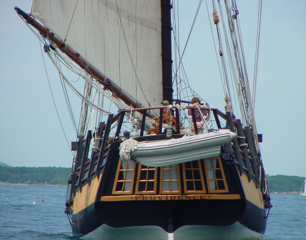
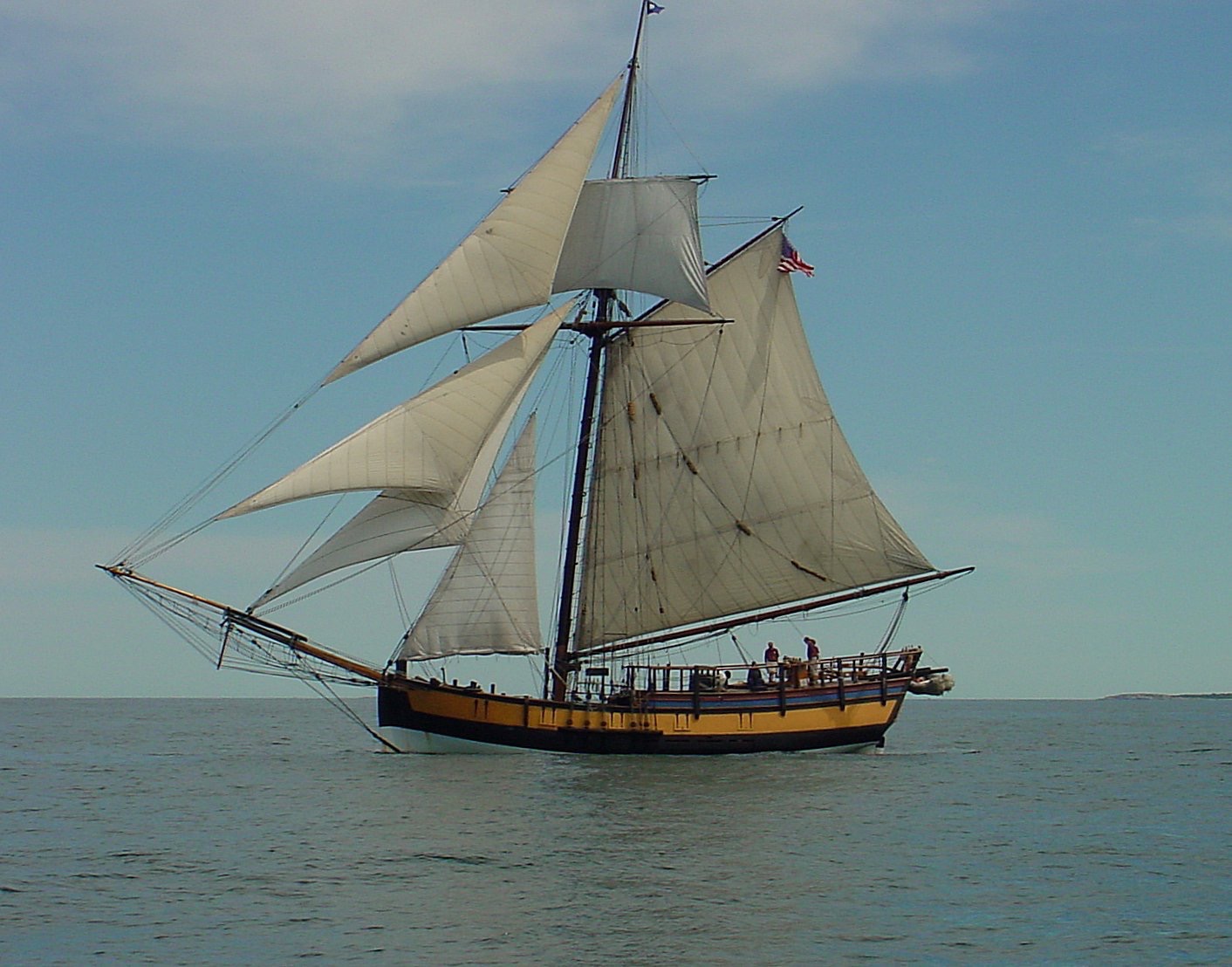
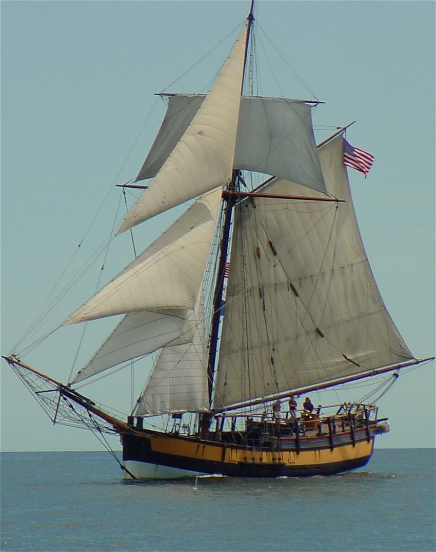
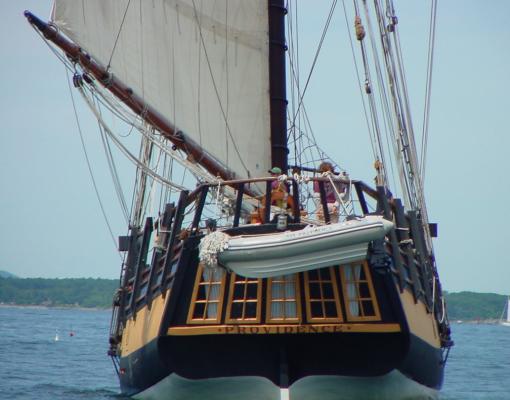
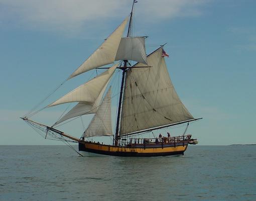
Just a bit of inspiration. S.O.S.

-
Nice to see that there are others interested in early American Men O War. Chuck that sure is a coincidence we are building the same vessel. I’ll see if the local printer can further reduce the sail and spar plan to 3/16” = 1’ I’ll send it out to you. Thanks for your posting of your work so far as I’m still cutting out lifts and your images inspire me to keep cutting away. I’ll post some images soon. I used the original station numbers to keep confusion at bay but even with the larger scale of my plans some questions still arise. Perhaps we can confer where the ???? comes up too often. Fortunately I can ask the former Skipper as well. Keep building S.O.S PS For a little inspiration.. I'll post some images of the reproduction sailing as soon as I can figure out out how to reduce them.
-
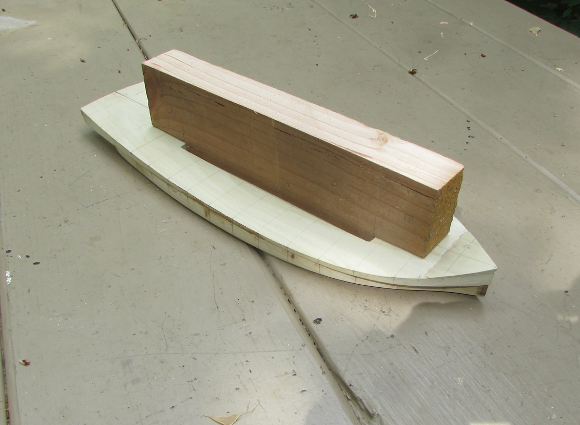
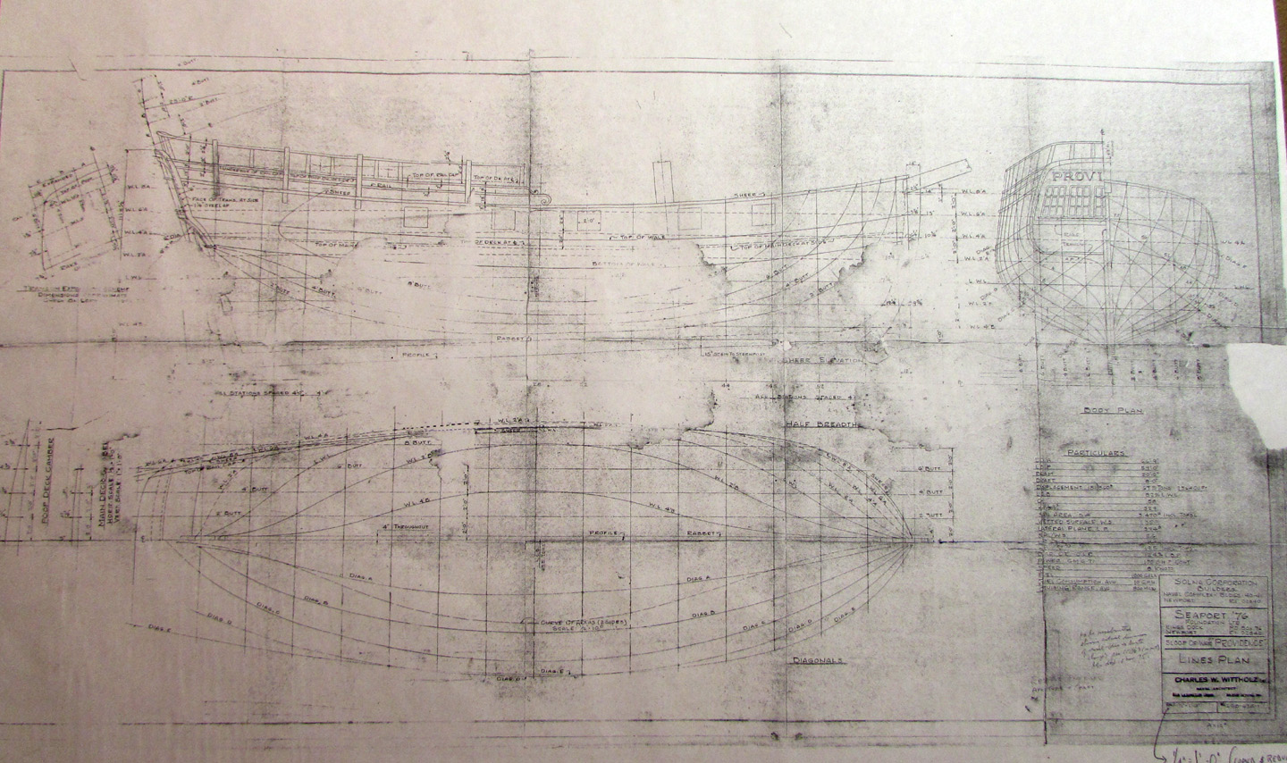
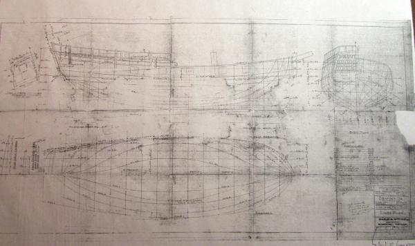
OK, I guess no one really knows just how this little raider appeared during the American revolution, but I assume some research was done before the building of a reproduction An architect by the name of Charles W. Wittholz designed the reproduction for the Seaport 76 foundation Newport RI.. This little vessel was the first command of John Paul Jones under the American flag and should have more recognition by kit designers and or modelers. I was fortunate to get a beat up plans from a former Skipper of the reproduction and will attempt to dope out just what the weathered plans are telling me. Any suggestions, hints comments etc are welcome. Here is one plan: The plans, ( shown in the image) are photo copied to the scale 1/4+ 1' and consist of the body and line plans ( some lines missing due to time, water and who knows what.) A deck fittings plan , Mast and spars plan but no rigging and a much faded bow and jib sprit plan. The vessel represented on these plans is the FG reproduction of the actual tall ship now awaiting her fate, and, as far as I know still damaged and not repaired at a yard in RI.. My idea is to construct the model using the lift method for the hull to the deck level and build up the poop deck with side bulwarks and deck. By coincidence each lift on the plan measures exactly ½" very convenient for me as I managed to get some poplar dressed to this thickness. I plan to cut out a portion of the main deck lift to allow some visual glimpse into the lower deck level. This hollow portion will also allow a the insertion for a temporary tendon affording me to insert the tendon into a vise while carving the inverted hull. When this is done I can beam over the hollow portion and cover it with decking..... Dowels will hold the various lifts in register during the glueing process. One may even be the mast but the rake could present problems. Anyway the hole for the mast can be drilled into each lift even before the assembly is glued. Well that's the plan thus far. Mind visualizing, this works so lets see what problems it might present in reality. Thanks for any interest. S.O.S.
-
looks good Bob. I feel like i'd like to miniaturizing my self and get next to that little stove. Or... at least sail aboard. SOS
-
Well I finally finished the model of my sprit rigged skiff Carrianne. I made 4 main sails and two jibs before i got a set of sails I liked. Here's another video of her sailing. I like it because the sound is good. http://tinypic.com/usermedia.php?uo=adkBqYNLltuvP10Ev533aoh4l5k2TGxc#.VF_6kTTF98E