HOLIDAY DONATION DRIVE - SUPPORT MSW - DO YOUR PART TO KEEP THIS GREAT FORUM GOING! (78 donations so far out of 49,000 members - C'mon guys!)
×


AON
-
Posts
2,863 -
Joined
-
Last visited
Content Type
Profiles
Forums
Gallery
Events
Everything posted by AON
-
 In this instance for the length and diameter of the part, three times.
 -
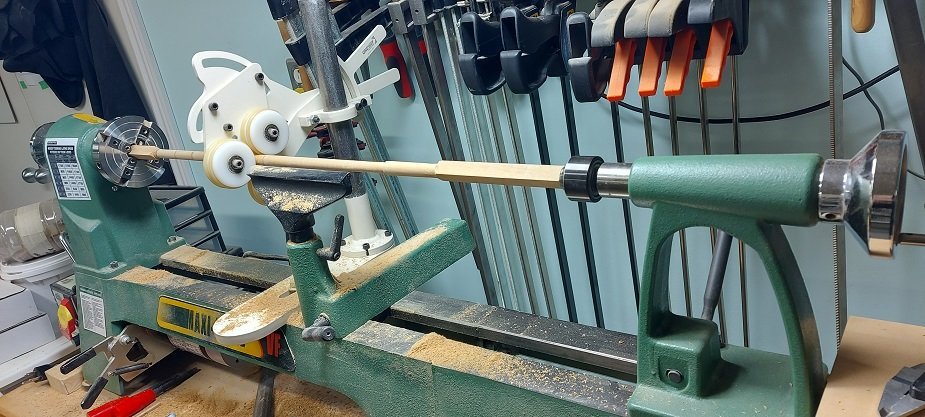
I had a busy September; getting things ready for fall and winter, and my son's wedding. I reworked the one carving (of the two) I had done for my kayak model for scale after having attended the NRG modelling realistic water workshop. I think this link will take you there to see the before and after of it: I have installed all the deck clamps I care to, including the orlop deck, and am presently turning my lower mizzen mast. As it is not a made mast it will be a bit easier. The shot below includes the "steady" Druxey asked about quite some time ago. I did a rough major diameter turn. Marked off the upper and lower quarters and presently have the top tapered. Going to work on the lower half Tuesday. Expecting company tomorrow (Canadian Thanksgiving Day). Once I have this and the lower foremast made I will install the three mast steps and then the deck beams.
-
Welcome aboard. You'll not find a better forum or helpful group of people than here at the MSW. I sent you a PM (private message).
-
Prior to mid 1800's port was referred to as larboard.
- 562 replies
-
- 2
-

-
- vanguard models
- alert
- (and 2 more)
-
I think she's water tight now!
-
Yup, sailors have been using both common whipping and sailmaker's whipping for centuries. Two quite different whipping methods. The former is quick and can slip off the end of a wet line, the latter is long lasting, so much so that it was used on the end of reef lines, two sailmaker's whippings in series. When the end of the rope wore down past the first whipping of the two in series due to it slapping against the sail the second took over until the sailmaker could take the sail down and change them all out again.
- 562 replies
-
- 3
-
-
- vanguard models
- alert
- (and 2 more)
-
The seizing in the video above is actually called common whipping used at the end of a rope instead of a back splice, to keep it from untwisting or fraying.
- 562 replies
-
- 2
-
-
- vanguard models
- alert
- (and 2 more)
-
Thank you "No Idea"... I usually feel as if I've no idea myself. I fully expect things to be a bit wonky. As the deck cross beams should fit into pockets in the clamp strakes (to keep them from rolling over?) I am thinking I could make adjustments with the depth of the pockets or alternately not do pockets but rather notch the end of the deck beam to sit properly (height wise) on the clamp strake. The will be a considerable amount of dry fitting involved to see this through properly. I may need a bigger scrap box. Eventually the top sides will be sanded.
-
Good morning Jaager Room and Space is 2'-8 1/2" Floor Timbers from 3 to C are 16" This leaves 1/4" (0.004") spaces Yes it increases as you move away from the DF to 1-3/4" spaces (0.027") and 2-3/4" (0.043") spaces No. 0-80 UNF thread has a major diameter of 0.06"
-
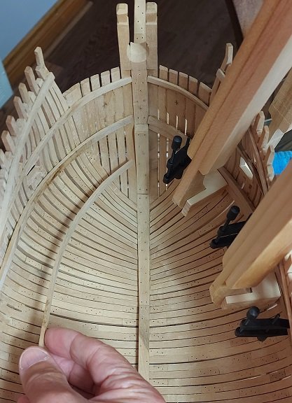
Thankyou Jaager. If you install every other frame there are gaps of more than adequate size for threaded bolts. Following the room and space per the contract does not allow an adequate gap... especially at the smallest of 1/4 inch gap (at 1:64 scale) between frames. Being a novice I didn't appreciate why modelers left every other frame out. As a matter of fact, I've learnt to appreciate more then I likely could ever remember... which means I am doomed to repeat some things. I agree with your statement regarding clamping pressure and I have been pleasantly surprised with what these simple large wooden clamps can do.
-
If you manage to get the camera at just the right distance, angled just so, and get the lighting just off the right amount... she looks fantastic! Don't get too close though because the fantasy is ruined. I double checked the heights off the plan, the distance below the gunport lower cill per the contract, the height needed for my 3D printed guns, and the wind direction. So it will definitely be off!
-
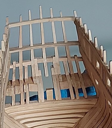
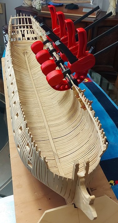
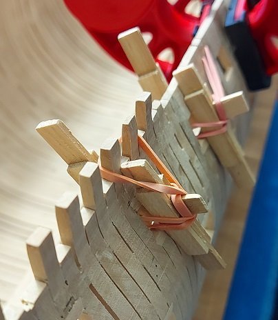
..... still (slowly) installing clamps. Here is a steamed 2nd or middle layer gundeck clamping strake bow piece being put into place. The mate (on the other side) already installed and clamped. seems I sometimes need one or both shoes on my wooden clamps whereas at other times I do not. I still haven't used any elastic bands on them. Very warm outside today, so I was working the dining room. I expect the weather to swing over to fall very soon. When that happens it is back to the dungeon.
-
Hamilton photographer, Brantford model set Guinness World Record for deepest underwater photo shoot The June 2021 shoot was recognized by the organization earlier this year. Modelling has taken Ciara Antoski all over the world. The Brantford woman has posed everywhere from Australia to Taiwan and Switzerland to Spain. But it was a pandemic-era photo shoot with Hamilton photographer Steve Haining that not only took Antoski to the bottom of Georgian Bay (Ontario, Canada), but also launched her into the pages of the Guinness World Records. Antoski and Haining, along with master scuba diver Mareesha Kulps, hold the record for the deepest underwater model photo shoot at 6.4 metres — or 21 feet. A Guinness spokesperson confirmed to The Spectator that the record was set in June 2021 near Tobermory.

-
- 6
-
-

-
In the old days, before CAD, when engineering drawings were by hand on a draughting (drafting) board with a Tee square, protractor, set squares, pencil and sanding board, or ink and pens on paper or velum, a draughtsman would be drawing hundreds of lines to scale a day, so he measured with the proper side of a triangular scale at the drawing scale. It saved time and was as accurate as the thickness of a pencil or pen nib allowed. Sure we had calculators. But not long before that we used slide rules. Good lord I hated those. Electronic calculators were a gift from the heavens. Time is money... why else would they invent CAD. Do you need them now? Only if you don't want to spend the time calculating equivalents.
-
Installed one length of the upper of three gundeck clamps using my large wooden clamps to hold them in place while the glue sets. Found the pivoting shoes didn't work so I rushed and removed them. Clamped without elastics but need a spacer block so I used a shoe. I'll get the other long piece on the other side tomorrow and work my way through them. I decided I will install the orlop deck clamps.

-
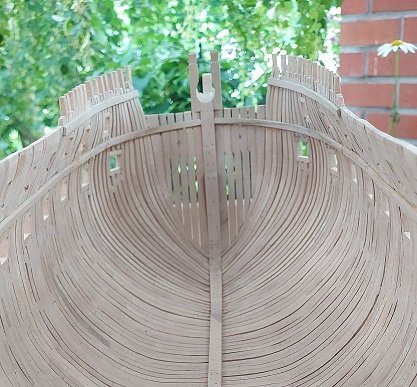
Stern counter beams done. Short stern quarter upper deck clamps steamed and clamped in place for shaping. I should have those on permanently tomorrow. Then I'll work on the gundeck clamps. I've not bothered posting photos as it isn't at all that exciting.
-
I used some string to measure the length of upper deck clamp required for the curvature of the bow. Cut my length, steamed and clamped it in place to dry. Glued and clamped that on the next day. Below you see it running up to the stem post. Today I sanded the stern counter beams. A little more work to go on them before I install the upper deck clamps back there. I wasn't really happy with my work closing up the stern but after today's sanding effort I feel much better about it.
-
Completed the sanding and installed an extra long length of the port or larboard side Upper Deck clamp yesterday. The contract reads that they were 4'-6" long scarphs "to be tabled into each other with hook and butt". As the actual connection will not be seen and I've yet to master such a joint I decided to give myself a break and do simple square end butt joints. The top edge of the deck clamps are about 3/8" below the gunports. I marked the upper location with a pencil to help locate them. Wood glue was applied, deck clamp put in place and holding clamps installed and left overnight to set and cure. I decided to run about 2/3rds of the length in one strip as I could just reach most of the length with my bar clamps and only needed to use three of the homemade elastic band wooden clamps through gunports. There is a short length required at the stern quarter and another at the bow. The bow piece will need to be steamed and clamped to shape. Moments ago I installed a similar long piece on the starboard side and I'll not touch this again until tomorrow. I'll work on the short pieces next, and then the Gun Deck clamps will be made in shorter lengths and clamped with the elastic band wooden clamps alone. I've still not decided if I'll bother with the Orlop deck. She is stiffening up quite nicely.
-
Yup...and they either connect to the sewer, run off to the street and collect in the sewer, or a stone pit at the far end of the yard. That works wonderfully until your run off water is overflowing (ground water flood) causing the sewer system to backup because it cannot handle the volume...then you have a flood in the basement.
-
All dry, water sensor/alarm installed, and a standing pipe and floor drain gasket on order from New Jersey (they don't sell these in Canada). I made a mess of the nice clean shop floor yesterday, cut and sanded my upper and gun deck clamps. Went to install them and it seems I hadn't quite done a good enough fairing job inboard at the upper deck level. So I'll be at that today.
-
It is almost back to normal now. Should be 100% by tomorrow night. We've lived here over 20 years and this is the second rain storm that the sewer system couldn't handle the run off. After the first we made sure to get everything off the floor but over time the memory fades and we get lazy. Not too much lost but the perimeter drywall got a good soaking. Some boxes ruined, stuff for donation turned to garbage and one extension cord to our cycle gone kaput. Most stuff was in rubbermaid tote boxes so that was fine No tools lost but all my sawdust was caked to the floor of the shop with a trail to the drain. Three stains on the floor to deal with. I built extra shelves well off the floor yesterday for any new stuff. The fans have done a good job drying things out but the humidity has gone to my paper plans hanging in the corner. At least the model was upstairs on the dining room table so she is fine. I'll be installing a stand pipe rubber gasket in the floor drain for next time.
-
Since it was raining quite alot this weekend I decided to go down to my basement shop to make the additional deck clamps. Discovered about 2 inches of water had flooded the basement coming up from the floor drain. The wife and I have been purging, cleaning, drying it all out since. Taking our first trip to the city dump tomorrow morning.
-
The pieces are quite deep (long fore and aft) so once again I did them individually.Next will be sanding and filing. When this is done I will get my other deck clamps installed and then make my fore and mizzen lower masts... then the mast steps and deck beams.