AON
-
Posts
2,874 -
Joined
-
Last visited
Content Type
Profiles
Forums
Gallery
Events
Everything posted by AON
-

Niagara by Alex-Ks1 - 1:7 Scale
AON replied to Alex-Ks1's topic in - Build logs for subjects built 1801 - 1850
Have you seen an eye doctor? I get an injection in my left eye every 9 weeks for going on 5 years now for one problem, and just had cataract surgery in both eyes last year. If it weren't for my regular eye checkups I'd be blind permanently in the left eye and going ( but reversible) blind in the right by now. As it is I now have 20/20 vision in both eyes except for a tiny spot just off centre at about 7:00 that is white if reading type (books) when I am tired, otherwise the other eye fills in the blank. -
I buy my wood in billets (about 4" x 6" x 6 feet) Cut them to about 18" in length on my table saw. Cut those small slugs into slices length wise (thicker than what I needed). Pass these through my 13" thickness planer to get them flat on both sides. Pass those through the Byrnes model Machine thickness sander to get the required thickness. Cut my pieces from that with a Byrnes Model Machine Table Saw and/or my 16" scroll saw.
-
I spent a considerable amount of afternoons this week working and reworking the stern timbers and beams to close it up. When I came up today the wife asked: "how did it go?", and I responded: "I learnt so much today", and she said: "what went wrong?" There's no pulling the wool over her eyes. No photos until I master this part... or at least earn an "atta boy".
-
Two clamps removed and they've set perfectly. The dog leg Frames are repaired. The clamps will be glued in place this afternoon.
-
You just had to put that out into the universe didn't you! 😳 It is easy being brave when you don't know better. I'll fix them BOTH tomorrow.
-
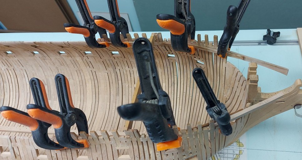
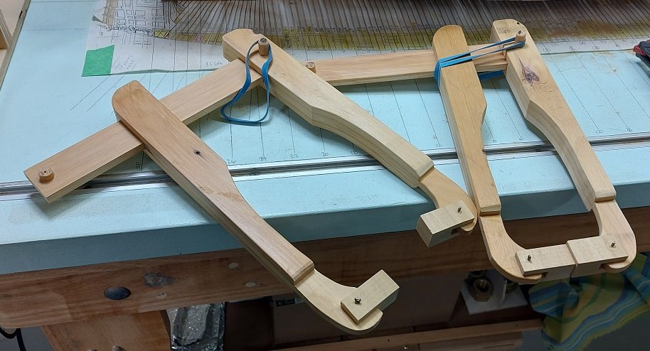
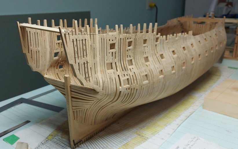
Roundhouse and quarterdeck clamps installed each in one length. Steamed and clamped the forecastle clamps. They formed up quite nicely with twist and camber but the knuckle doesn't set against the hull so I will do them again with more clamps. I had propped them out at the bow with a spacer to accommodate spring back and that seemed to work for the most part. Speaking of (spring) clamps to hold the wood strip deck clamps to the hull. All mine are quite short and lack the reach needed for the upper deck at the bow and stern, the gun deck and the orlop deck (if I'm putting this in). I could make something to reach through the gun port which takes care of 80% of the clamping needs but what about the rest, and the orlop deck has no gunports to reach through. I found a YouTube video by an airplane modeler (key words for your search are "elastic band operated clamps") and decided to make a couple and see how they work. Once set they do not open one iota. I made a few modifications to how the elastic connects, the bar stop assembly and the clamp nose piece assembly (cotter pins) and my dowels are dry friction fitted so the whole thing can come apart if needed. They are made of hemlock with pine nose pieces and maple dowels. Extremely light and as they are a soft wood, if they topple over nothing gets damaged. I estimated worst case I needed a 6" reach and they provide 8-1/2". Now I'll likely make a couple narrower ones for nesting closer together, and a few much smaller to reach through the gunports.
-
I see it now. Funny how the mind goes where it wants to. Regardless, when the time comes I think you can set a reasonable gap by adjusting the angle ever so slightly. But then again... I am no Druxey! 25 years eh? and I thought I was taking long. Thanks for making me feel better.
-
If only I was. ☹️
-
Regarding the bowsprit clearance. Can't that be done by changing the angle ever so slightly to suit. No one will be taking a protractor to it.
-
Niagara by Alex-Ks1 - 1:7 Scale
AON replied to Alex-Ks1's topic in - Build logs for subjects built 1801 - 1850
Go to your very first post and pick the three dots at the top right. That will open a menu. Pick edit. You will see the title displayed and you can edit it. Pick save. -
Niagara by Alex-Ks1 - 1:7 Scale
AON replied to Alex-Ks1's topic in - Build logs for subjects built 1801 - 1850
Hello Alex. I am not aware of your location but if it will be of any help I have some photos of the Brig Niagara. I was on the replica for a day cruise and banged my head quite a few times when down below. She was quite shallow because of the sand bar entering or exiting the bay in which she was built. Even at that they had to remove the guns to lighten her up more to clear and the British were there waiting but didn't realize she had no guns so didn't attack. You might want to correct the spelling of the ship's name in the title... you're missing a letter. -
All fixed. Decided not to take the over thickness starboard clamp off as the alcohol to do this would de-glue the frame and chock connections behind it. I sanded the port roundhouse clamp to the proper thickness and used it to mark off the proper thickness of the starboard clamp that was glued in place. I then sanded it down to below the line, this taking into account the thickness of the pencil line outside the thickness of the clamp used as a template. At this time both are attached. Today I made stock for the quarter deck and forecastle clamps and they will be installed next.

-
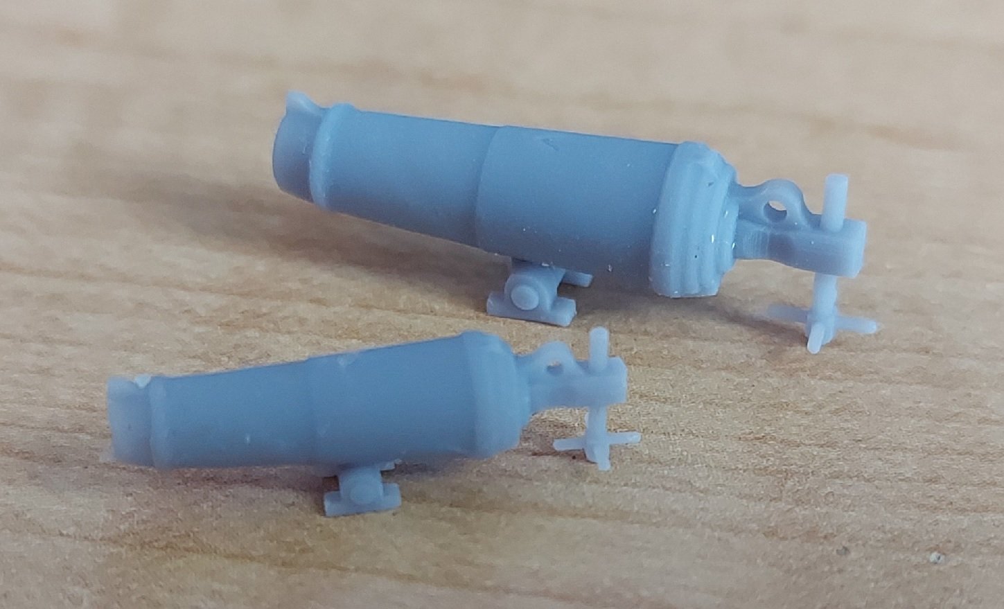
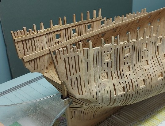
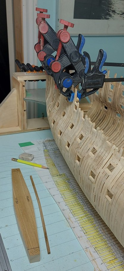
The Roundhouse Clamps have been made, steamed and bent to fit. The starboard side has been glued and clamped in place. In the photo below you can see my form used to shape the clamps to. The port side clamp is on the table next to it. I've started the Quarter Deck and Forecastle Clamps at 4" x 12". 4 inches thick seems awfully thin compared to the Roundhouse clamps at 11" x 13" but that is what they are. ***EDIT: I made a major boo boo. The size of the Roundhouse clamps didn't make sense compared to the Quarter Deck clamps. I then looked at the Gun Deck and Orlop deck. I checked the image in the Bellona book. I went back to the original contract document. The 11 is actually a 4. The way it is written it looks like an 11 to me. Now I have to try to get the one off and do it all over. My sailor words are creeping up through my throat from my gut. Also, I received my resin printed carronades just over a week ago and they look fantastic! 8 each x 18 Pdrs and 2 each x 32 Pdrs. The larger is about 1" long and the smaller about 13/16" long I have no idea why I waited a week to post this other then they are very delicate (screw nut handles) and I don't want to handle them more than necessary. I'll get them painted and stored away in the next few days.

-
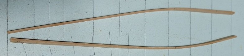
I'm starting with the roundhouse clamps at 11" thick and 13" broad (height). Clamps were normally 25 to 30 feet long but I read the roundhouse clamps were normally made in one piece. Mine are about 49 feet long. That would be a beast to lift in place at practically 1 ton of weight. I made a quick mock up out of scrap poplar, marked off the heights for the clamps and laid the mock up in to check it out. It ran below the top of the door opening. Double checked my pencilled in door locations which were spot on. I found that the original framing plan had the round house deck beams drawn in at double thickness. After adjusting things the mock up just cleared. I then made up the two clamps in Castello boxwood, a paper template of the wall curvature, and then a form to clamp my steamed clamps to. When dried I had 1/8" spring back. Adjusted the form and things are re-steamed, clamped and setting now.
-
Will this be the master for casting more?
-
I deleted my earlier post as I made an error having read all the clamp descriptions at once I got confused and melded them. Need to step back for a moment.
-
I think it looks fantastic!
-
Looking at the size of the roundhouse and quarterdeck clamps now.
-
I wasn't planning on that next but it would definitely brace things before cutting out the doorways. Hmmmm. Change in plans????
-
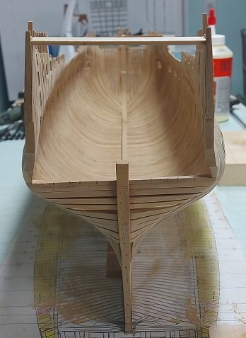
Rebuilt the side quarter and faired (sanded). Looking considerably better this time. I installed a temporary brace across the top of the counter timbers to try to steady things a bit while I work in that area. Marked of the top timbers and quarter doorways. These will be cut down/out this weekend, then I'll get the cills installed. I am hoping to do a better job on them also!
-
I'm surprised no one asked what the heck that means.
-
That is very interesting. The Royal Navy BR67 - Manual of Seamanship 1937 reprinted for the Royal Canadian Navy in 1942 lists four types of construction: 1. Clinker built 2. Carvel built 3. Diagonal built 4. Sewn boats Clinker built boats existed well into the 1970's until replaced by the new Fiberglas hulls. We had one, a cutter built for us (local sea cadets) in the 1920's and they were at the reserve base boat shed at HMCS Star and summer training camp HMCS Quadra in the 1970's. My interest is with the Royal Navy of 1790-1800.
- 24 replies
-
- 3
-

-
- Small boats
- cutter
- (and 2 more)
-
That certainly shines a much brighter light on things. Thank you.
- 24 replies
-
- 2
-
-
- Small boats
- cutter
- (and 2 more)
-
Thank to all, and yes it did seem to take a wee fork in the road but enjoyable none the less. I have been peeking in but have be otherwise occupied over the last few days to be able to comment. The first few posts put some light on the subject. I've found that Wolfram zu Mondfeld wrote in his book Historic Ship Models, pg.192: The cutter - A clinker built general purpose boat with up to 12 oars and fitted for sailing - introduced in the latter part of the 18th century. The carvel built yawl of 4 to 6 oars was the smallest ship's boat on board until the late 18th century, when it was superseded by a small 18ft cutter pulling 4 oars, known colloquially as a "jolly boat". The gig - A long narrow, fast boat for personnel transport with 6 to 8 oars. The gig was used for carrying the Captain and usually his private property. With its introduction in the late 18th century the gig took over part of the duties of a pinnace or barge. Only one gig was normally carried. The images on the following page 193 show the gig to be single banked and the cutter double banked. In Ship Modeling From Stem to Stern by Milton Roth, page 136 -137: The smallest carried aboard was the dinghy or jolly boat, ranging in size from 12 to 16 feet. By contrast, the largest was the longboat or launch. The Longboat Launch (first time I've seen longboat and launch together so I guess that answers another question, or does it?) was 20 to 50 ft long, double banked The Yawl Barge was 24 to 35 ft long with 8 to 16 oars, single or double banked (which in profile on page 140 looks like a shorter launch, but per the description the lengths overlap so were they the same thing up to 35 ft? This was a Yawl Barge, what about the Yawl and the Barge?) The Pinnace Cutter was 20 to 50 ft long with 8 to 16 oars, double banked and was the second largest service boat. (so was the Pinnace a Cutter, apparently not according to W.E. May in his book The Boats of Men of War as they are listed separately. Also, the pinnace was carvel planked and the cutter clinker planked... ) The Dinghy Jolly Boat was 12 to 16 ft with 2 oars, single banked (virtually a small boat rowed by one man... like when I go fishing. I read "jolly" as a fun little boat.) I find it all very confusing as most overlap in length, number of oars, and even dual use of names... and then different sources don't seem to agree. I imagine the deciding factor might the end use assigned to the design. Where might that be listed? I hope this helps people understand my confusion.
- 24 replies
-
- 1
-
-
- Small boats
- cutter
- (and 2 more)
-
Could someone please explain the difference between a Jolly Boat, a Captain's Gig and the shorter cutters. I understand a Jolly boat was 18 feet long or less and was used to transport people from ship to shore or ship to ship. I understand this is the same description of an 18 foot long cutter Are the then the same thing? What about the Captain's Gig?
- 24 replies
-
- 1
-
-
- Small boats
- cutter
- (and 2 more)