HOLIDAY DONATION DRIVE - SUPPORT MSW - DO YOUR PART TO KEEP THIS GREAT FORUM GOING! (89 donations so far out of 49,000 members - C'mon guys!)
×


AON
-
Posts
2,868 -
Joined
-
Last visited
Content Type
Profiles
Forums
Gallery
Events
Everything posted by AON
-
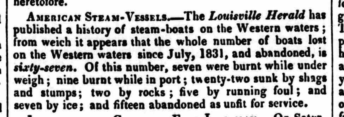
A talley of the loss of American steam ships - 1834
-
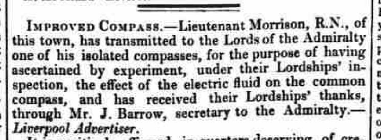
I suppose nothing much became of this as I cannot find the fellow in a web search - 1832
-
and the King of France has a new barge - 1832
-

Bowsprit Fairlead - what rigging uses this?
AON replied to AON's topic in Masting, rigging and sails
for anyone that reads this in the future, after looking at conventional models on the RMG website, and having found one 74gun 3rd rate English MOW date 1760 that I could see some detail of the fairlead, I had decided yesterday to go with nine holes, and use all but the top hole located at 12:00 for each of the lines that tie off at the forecastle timberheads. the top hole would be left empty, as a spare, and this would provide a wide clear walkway up and down the bowsprit. I've mapped out all the standing and running rigging for the bowsprit/jib boom, spritsail and spritsail top sail for my build and posted them as a PDF in my build dated yesterday, posts 1044 an 1046.- 1 reply
-
- 2
-

-
Thinking logically.... people need to walk out on the bowsprit, so lines through the fairlead cannot be a trip hazard, so maximum foot clearance space between them would be a plus. At 9 holes the space would be about 8 inches (203mm). At 7 holes the space would be about 10 inches (254mm) which is better What I was looking at was a 74gun 3rd rate MOW of 1760 and that model seemed to have nine (9) holes. My ship has eight timberheads with lines secured to them. These eight lines would be Nos. 1,2,3,4,7,8,9,10 on my list in my PDF word document above. If I go by this list, it leaves one hole in the fairlead unused, a spare... and I would assume this is located at 12:00 leaving a 16 inches (406mm) open walkway. I assume not all the holes would be used. Possibly the outer timberhead lines might not pass through the fairlead leaving more spares... or to be used by a couple other lines. Makes sense to me. Nine holes it is then. Yes Druxey, I am going down to the dungeon to start sanding again.
-
I spent a good part of the morning scouring the RMG site with model images zoomed in and then my screen zoomed in and my wife saw me with a magnifying glass... that sight must have been hilarious. I found one model that I could focus on and it seems to have nine (9) holes in the fairlead. I wish there were more images and sources on this item. With so few holes I imagine the outer most lines would be eliminated from passing through the fairlead. So I suppose I should review my list of possibilities.
-
Thank you Druxey, but with the accompanying word document it is much more than a nice illustration, it is a map. seven or nine holes? funny it should be an odd number. TFFM has seven, but others have even numbers up to twelve. none have rigging as few install sails Bowsprit + Jib Boom - Standing + Running rigging.pdf
-
Quick update... Still sanding off and on, and having a wonderful time of it. I've chiselled what I can, and hasped and flexible filed a bit more, then #80 sand paper, followed by finer grades, but it is very slow going. Finished my drawing of all the lines for the Bowsprit and Jib Boom, and created a MSWord doc for them all so I do not have to relearn it all in a few years when I get to this point, but for now, I have enough information to add my rope wooldings, rings, cleats and saddles to the bowsprit and jib boom I had made. It has been good exercise for the brain, I learnt quite a bit. I have posted a question in Masting and Rigging about the fairlead as it is the only item I am not 100% certain of. Some of the running rigging passes through holes in the fairlead to keep them organized and from getting fouled up. The problem is I have not found one source that states the number of holes or lines or what they all are. So this is one small but important detail to allow me to wrap that up. Bowsprit Rigging Layout.pdf
-
I am trying to verify the number of running rigging lines from the Bowsprit/Jib Boom yards and sails that pass through the fairlead located on the bowsprit of a English 74 gun Man of War launched in 1786. I have come to realize there were quite a number of changes (upgrades) in these ships during their life time and it has been a challenge when sources disagree due mainly to their date of reference. Referencing the following sources: Rees's Naval Architecture (1819-20), Steel's Rigging Tables (1799), The Anatomy of Nelson's Ship's, The Masting and Rigging of English Ships of War (1625-1860), The Fully Framed Model (including the 3D renderings by Dennis Ranaric of Croatia for Admiralty Models), and the Rigging of Period Ships, I have narrowed it down to the twelve lines of which only two are clearly stated in Rees's to have done so. Lines identified as possibly feeding through the Bowsprit Fairlead: 1. Jib Staysail (In) Down Hauler (1); 7/8" dia.; secures at Forecastle Timberhead #6 2. Jib Staysail Out Hauler (1); 1-1/4" dia.; secures at Forecastle Timberhead #5 3. Fore Topmast Staysail Down Hauler (1); 7/8" dia.; secures at *Forecastle Timberhead #3 ? 4. Fore Staysail Down Hauler (1); 7/8" dia.; secures at *Forecastle Timberhead #4 ? 5. Spritsail Topsail Yard Halyard (1); 7/8" dia.; belays to a rack over the bowsprit (REES pg 92) 6. Spritsail Yard Halyard (1); 1" dia.; 7. Spritsail Topsail Lift/Sheet (1 - port); 7/8" dia.; secures at Forecastle Timberhead #1 8. Spritsail Topsail Lift/Sheet (1 - starboard); 7/8" dia.; secures at Forecastle Timberhead #8 9. Spritsail Lift (1 - port); 1" dia.; secures at Forecastle Timberhead #2 10. Spritsail Lift (1 - starboard); 1" dia.; secures at Forecastle Timberhead #7 11. Spritsail Topsail Clew Line (1 - port); 5/8" dia.; 12. Spritsail Topsail Clew Line (1 - starboard); 5/8" dia.; *Forecastle Timberhead locations 3 and 4 available as listed for Flying Jib Out/In Haulers I was hoping someone in the forum may have "hoed this row" and so might be able to help confirm my list as I have seen builds with eight, ten, and twelve holes, but no source I've found adequately describes the fairlead nor the rigging lines that utilize it to keep those lines from fouling. Thank you in advance.
-
Thank you Druxey. Although I pride my visualization skills, I've learnt over 40 years of relying on it that you cannot imagineer everything.
-
Thank you for the response Druxey The Anatomy of Nelson's Ships, pg 227/228 clearly state the Guys run aft over both the Spritsail Topsail Yard and the Spritsail Yard. The same book, pg 236 states the (aft) Spritsail Yard hangs about 2 feet beneath the Bowsprit. I quickly modified my drawing and find I would need to drop the ST Yard about 34" to clear over top. Pg 239 states the Spritsail Topsail Yard has no sling. The weight is taken by a parrel. It must be lowered to work, so the parrel trucks and yard lashing must accommodate this distance.
-
Popeye: From what I can find there was a period where all yards/sails were included in the rigging of the ship and with the addition of the Dolphin Striker and related rigging the Spritsail Topsail and it's yard were removed. When the Dolphin Striker rigging was further improved the Spritsail and it's yard disappeared. In that time period that they both existed the Guy must (in my mind) run under the forward yard or it cannot be hauled taut, and so would be useless. Running over the forward yard would bite into the top of the yard, and that seems counterproductive to me. The more I think about it, it seems plausible that the Guy was simple slackened off, as I mentioned in my response to Druxey. This seems the simplest answer. REES (and STEELS) couldn't be wrong. Alan
-
Druxey: I do not know positively. I imagine these sails are best used when running, and if that is true then the aft sail being larger would make the forward smaller sail less effective BUT as the mast is angled at 30° this exposes almost 12 feet of the upper portion to catch wind so I would guess the answer is a very possible yes under light wind conditions. The yards of these two square sails can be angled, I assume when the wind is off the stern quarter, or to assist turning the front of the ship around. In any case the Guy does not run outside of the mast far enough to avoid the Spritsail Topsail and so would pass through where the sail would be, unless the Guy was removed, slackened off to allow the sail to set, or not used at all. The second choice (slackened off) seems to make sense. Is this the answer?
-
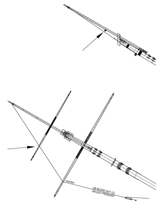
I've noticed many irregularities and contradictions in various books with regards to the rigging of the bow masts, so to untangle the mess in my head I am attempting to plan my jib boom/bowsprit rigging for down the road and am creating a map for me to follow when I get to this stage. My many sources show rigging that doesn't seem to make sense and not installing sails on your build would mean they would likely not be noticed. For example: This image clearly show two yards (Spritsail Yard and Spritsail Topsail Yard) with standing rigging running through the dolphin striker clearly making it impossible to set these sails. After banging my head I was steered by a good friend to appreciate that in the year of my construction there was no dolphin striker! Could someone help me please to understand how this next one works.... Looking at REES'S plate IV (rigging plate III) Figure 2 the Jib Boom Guy Pendant (items 49 and 50) run from the head of the jib boom down through a thimble stropped to the Spritsail Yard (furthest aft) and then to a block and tackle system. The description on page 91 confirms this. When I draw it out the pendant runs under the Spritsail Topsail Yard (furthest forward). (location identified with arrows on the drawing) This means that if there is a sail on the Spritsail Topsail Yard the Guy Pendant goes through it. Commons sense dictates this is wrong. My question: What am I misunderstanding?
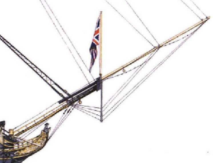
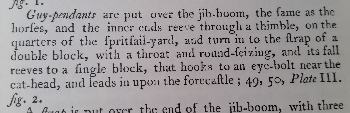
Fig2.jpg.e6941973243c305d169571cc50c58e6e.jpg)
-
I should post that I've had some PM with MESSIS and I had sent him a corrected image for the French rigging. The image in post 5 above is more, I believe, for English ships.
-
Does this seem a bit drastic... 1832

-
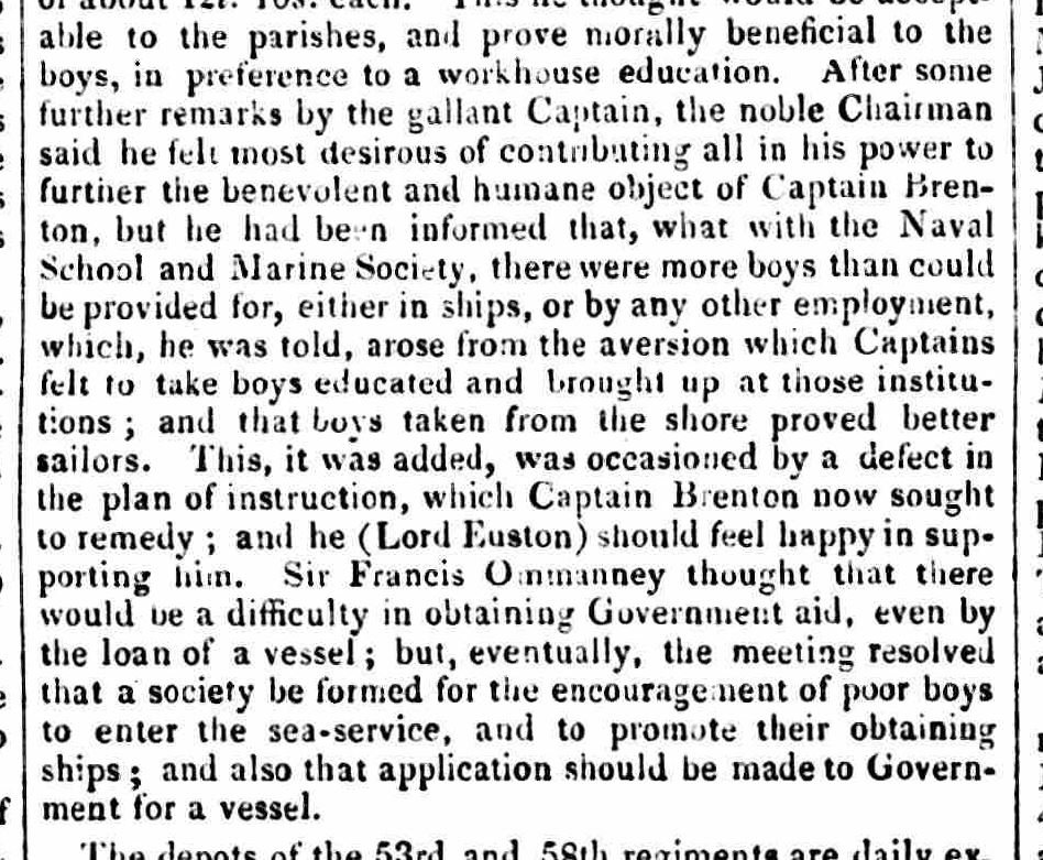
very interesting reads Druxey ...then came the Boys Naval Brigade, from which came Navy League Cadets, and then Sea Cadets.
-
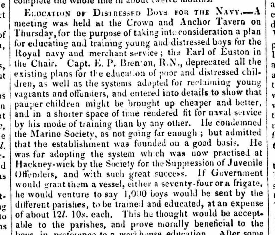
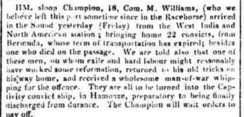
Oh what to do with the vagrant and offending youth overtaking the realm? 1834
-
A sad state of affairs... 1833
-
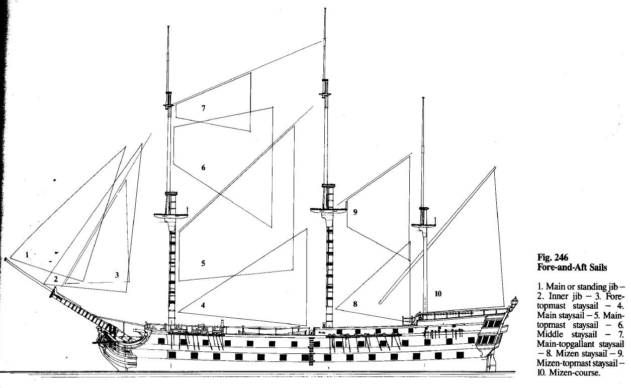
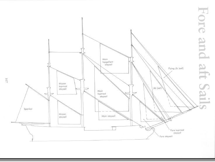
With no flying jib boom it would be Jib Sail, (out front) Fore Topmast Stay Sail, and Fore Staysail (back aft). Your images do not have the Fore Staysail rigged or raised. The traveller on the Jib Sail is hauled about halfway aft on the jib boom.
-
John Dalberg-Acton, 1st Baron Acton:

-
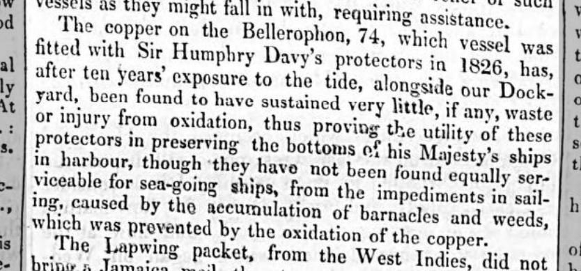
10 year result of testing copper plating - 1836
-
The more things change, the more the stay the same. Or do they - 1832
-
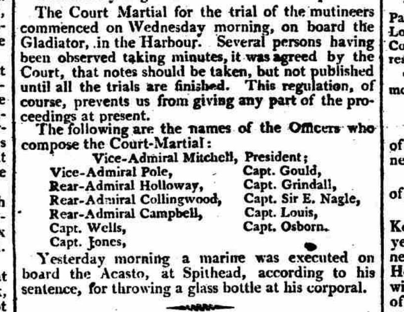
1802 - a little harsh? It was only a corporal after all... maybe for an admiral.
-
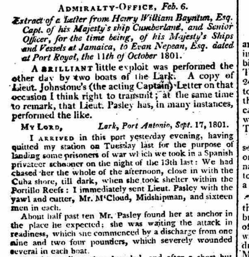
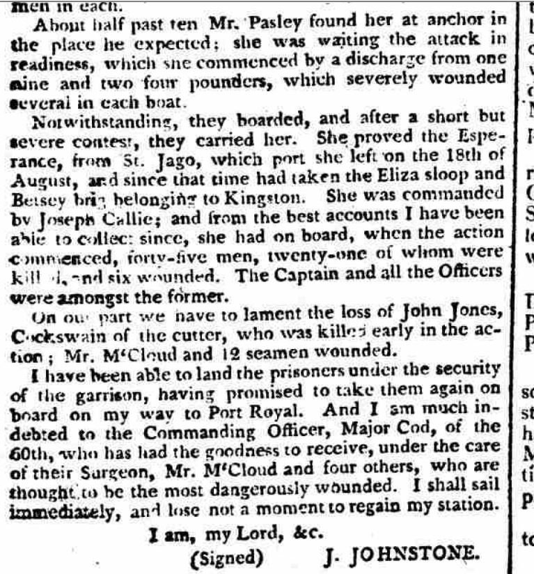
1802 - the Cumberland taking a Spanish privateer schooner in the Caribbean - 2 parts