
AON
-
Posts
2,585 -
Joined
-
Last visited
Content Type
Profiles
Forums
Gallery
Events
Everything posted by AON
-
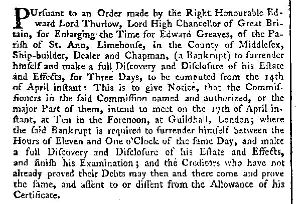
 Druxey, That is what I originally thought... some ones thoughts scribbled on the contract. But there are so many other things ... the 1805 date for example. I usually love a puzzle and my darling wife (the super sleuth) has been doing what she does best ... looking for clues and finding additional info on the bankruptcy and the date of death for dear Mr. Edward Greaves. I e-mailed my contact at NMM this morning to ask for help deciphering the contract notations and hope I have better luck with a response then the poor fellow I had provided the contact info to for quotes on plans elsewhere on this site. I also asked my NRG mentor early yesterday and had not heard back from him as yet, I prefer to think he is working on it rather than him "having a life"! I need to learn the virtue of patience!
 -
Good morning all. Thank you for the additional info and thoughts Mark. I was looking at the data I had printed out / collected from various source including Wikipedia (which I am told to take that particular info with a grain of salt) and very little agrees with each other. As for the NMM and their plans... it is my understanding that they still have stuff that is waiting to be reviewed, identified and catalogued so with my luck I am positive it will all come to light the day after I am done After one nights sleep on it I had another thought.... I wonder if there may be an "expert" at the NMM that can make sense of it all? Lord knows what strange things they've seen. As for the Billy Ruffian, as a 13 year old she (the sea cadet corps in Welland, Ontario, Canada) saved me. Also... If not for the sea cadet corps I would have never met the young girl that I now share my life with, my wife. I went through the ranks to eventually become Chief of the corps (cox'n) and then as an adult went further to be Officer Commanding the Corps for five years. Although as an old man I had no involvement for the last 20 years of her existence, it broke my heart (along with many other men and women) to see her shut down. This is my attachment to the name Bellerophon and why I am so keen on building this particular ship and not HMS Elephant for which I seem to have easily acquired all the info for.
-
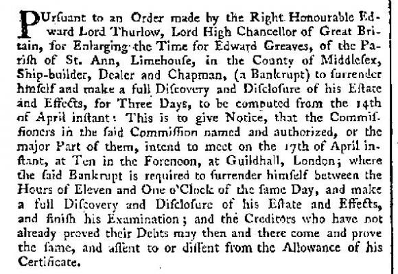
Don (and all) The scribbling in the upper left corner of the first page of the document seems to read "Ships Contracted for 2h Jan 1805". I also see a very small 1805 scribbled above the heading "INTEREST" and below the eighth work payment during seasoning on the second to the last sheet. I am going to sleep on this for a short while and see if any sense of it comes in my dreams. Until then I'll ask again if anyone knows that they might spend 180% of the original cost to make her sea worthy and serviceable again after the Battle of Trafalgar. Would they actually make her 8 feet longer (how???) and about 9 inches wider (thicker boards on the hull???) Thinking back to the seasoning and launch delay... were the sums in the left column late payments due / made with interest? Since there was no war would the government be eager to hand out moneys, hence i wonder the cause of the gentleman's bankruptcy. (this doesn't make sense to me but it was a thought I had) I know there are quite a few forum members that are extremely knowledgeable (and talented) and hope one might shine a brighter light. More than willing to PM some select portions of sheets of the contract to study. Maybe I should post this problem elsewhere on this site so someone not visiting might see it... good idea. Will do that in the morning as might allotted play time is up for this evening. Mark: presently waiting the reprint of HMS Bellerophon (announced in the books section of the site) to arrive and wonder if it might reveal anything with regards to size. G'night world.
-
Thank you Mark According to the contract she did supply an income during the seasoning period. There were payments at regular intervals somewhat equal to the build payments
-
I know she had extensive damage during that battle I imagined the contract was referred to for the refit. Would they have made her longer and wider? Doesn't seem likely to me. Is this something they would have done? I cannot imagine spending almost twice the cost of the original build for a refit... I'd have used her for target practice. None of it makes sense to me.
-
MY HEAD IS STARTING TO HURT Today, if I were making any changes to a legal document I would initial each and every change. I personally would add the date to each also! There are an awful lot of "notations" on the contract and 180% original payments seem to be recorded in the margins. I want to be true to the original build... but I suppose the right thing to do is whatever is right for me. What is right for me? What a conundrum.
-
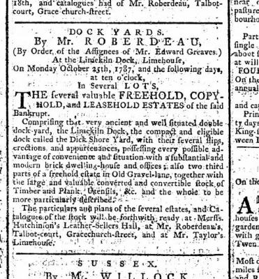
One more newspaper clipping that tells more about the shipyard Morning Chronicle and London Advertiser Sept 12 1787 re Edward Greaves Certainly a business will go under if not managed well but he was contracted by the government and knowing how timely governments are at collecting versus paying out today I wonder if he had issues with "delayed payments" versus creditors. This side trip into the builder is all very interesting. Regardless, the longer I stare at this contract the more it seems obvious all references to this ship being like the other Arrogant Class ships are likely wrong. HMS Bellerophon was eight feet longer. I suppose I need to review Steels and Rees and hunt for other 175 foot 74 gun ships to better understand / visualize the framing, etc...
-
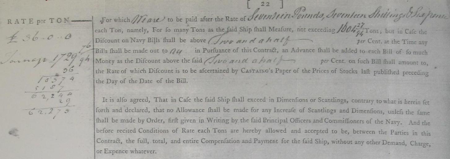
Looking over payments HMS Elephant per contract, no noted amendments = 54530 pounds HMS Bellerophon per original contract = 50704 pounds but with all amendments and payment total made in margins = 91694 pounds !!! I cannot believe the navy filed a contract with all these amendments that they were not in agreement with All notations therefore must have been agreed to amendments Am I "out to lunch" with my conclusion? Then again, why the bankruptcy?
-
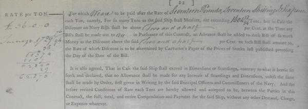
(part 2) When we look at payments... The contract clearly states "not to exceed 1604 - 27/94 tons The penned notation in the left column reads 1729 - 76/94 tons The last paragraph of this section clearly states "... in the case the said ship shall exceed in dimensions or scantlings contrary to what is herein set forth and declared that no allowance shall be made for any increase of scantlings and dimensions ..." In other words he would be out of pocket for changes instigated by himself. This contract was signed in February of 1782. The ship was launched 6 October 1787 and completed by March 1787 Strangely enough Edward Greaves was bankrupt in 1787 !!! Did the Bellerophon do him in? Did he ignore the contract? Was she 175 feet long?

-
Druxey, (Part 1) The "as built draught" is of HMS Elephant The non-amended contract for her reads the same as the one for HMS Bellerophon The contract for HMS Bellerophon has the additional notations You will note the contract clearly states 168 feet but just below it is penned (what seems to be) 175 feet I had mistaken the 5 to be a zero. Don had caught this. It seems the Length of keel for tonnage was amended to 144 feet 1-5/8 inches The builder was Mr. Edward Greaves and Company of Limehouse, County Middlesex. There are quite a few other notations throughout the contract. When we look at payments....

-
Thank you all for the words of encouragement. I fear stepping away might cause me to be more forgetful. (Is that possible?) Regarding the 168 feet versus the 170 feet... Don has zoomed in on it and tells me it looks more like 175 feet and having done the same last night I tend to think he is right. The tiny five being very similar to a zero. (the 8's still look like freakishly twisted 6's) I will stick to my original decision as I believe there cannot be any possible way a builder would put that much more out of pocket expense into a build 168 feet it will be. I am still going to try and salvage my work to date it will mean re-establishing the station locations and when that is done re- fairing the hull.... and that part was such a joy. Hopefully it won't be too bad as I keep having trouble acknowledging the tiny scale. 40 plus years of doing exactly the opposite does not make it easier (drawing small and trying to see it in my mind at full scale) With the weekend around the corner I hope to get adequate time in to resolve my problem
-
Don As explained in our PM (for anyone else wondering) as a habit at work we do not use configurations as they have been the result of some major $$$ errors. If someone forgets to set to the proper configuration someone else may not realize and WHAM all of a sudden your expecting a pink slip. If I had worked in configurations and this was the error I could easily pick the other one. If you knew how many times I opened the file and started working on it only to discover I was working on the Back Up copy....dumb move once ... really dumb the forth time Druxey Not making excuses but it can be difficult trying to focus 1-1/2 hours in the evening after spending 8 to 9 hours staring at drawings and documents on a computer screen. I tend to feel relaxed when do this stuff after the stress of work ... but the last few days of this has not been that relaxing! Even the 45 to 60 minutes in the morning can be dangerous (am I really awake or am I dreaming about my build????) I am narrowing in on it and believe this is what happened I think it all happened between my guessing at the station spacings while working with images of the drawings, and then finally receiving and trying to work with the contract. It seems my station locations are buggered I just laid it all out in 2D CAD - Draftsight - and now question the spacings of the forward and aft cant frames A discussion for me and my mentor I am not one to give up ............ but it certainly humbles a fellow Alan
-
HOLY MOLLY !!! fan-bleed'n-tastic
-
A "do over" would certainly reinforce what I hope I've learned... just not looking forward to starting from scratch. It would definitely be better organized the second time. Can't seem to turn my back on the progress I've made to date. My NRG mentor suggested I might have imported the drawing to CAD and traced it versus trying to measure everything. I'd still have to contend with paper stretch but it would be faster and lines would align. Starting over??? Holy old bald headed Saint Dulabon... what have I gotten myself into?
-
Good morning world! I have been busy building my modelling table and dealing with summer. Getting back into all this with fresh eyes and I've noticed a few things I had done that I cannot recall "why". (a great advocating point in favour of the build log notes idea mentioned in another forum) Seems I have a double set of station lines and I've no idea why.. apparently I had changed something and left the original set in. I am trying to determine if I had erroneously used a wrong one anywhere I've measured (what I believe to be meticulously) off the drawing and laid out the keel, stem and stern posts and rabbet line along with shown scarf joints and they do not align properly. . At the moment I am extremely frustrated and am very close to shelving what I've done to date, chalking it up to a learning experience and starting over from square one. Another thing that has been nagging at me is the fact that I'm working off the Elephant plans but the Bellerophon contract has a penned notation (correction) to the length changing it from 168 feet to 170 feet long. This extra 2 feet (1/2" at 1:48) won't leave my mind... I cannot let it go. I will continue to try to determine if I can salvage what I've done or start over. I cannot adequately describe the feelings I am having at this moment Alan
-
what is the ideal modelling table?
AON replied to AON's topic in Modeling tools and Workshop Equipment
Thanks guys Can't wait to start building on it Drafting (draughting) table? I moved on from that about 25 years ago. Still have my pencils, compass and accessories, brush, sanding board, triangular scales, french curves......... Might even have a few sheets of D size paper in a tube. I'd need a cover ... and a place to put my model!! -
what is the ideal modelling table?
AON replied to AON's topic in Modeling tools and Workshop Equipment
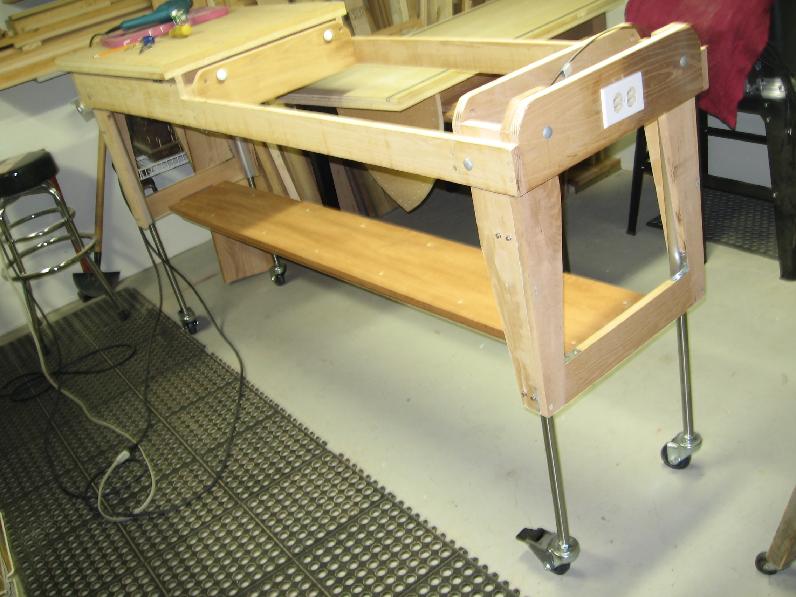
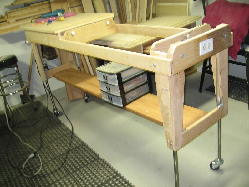
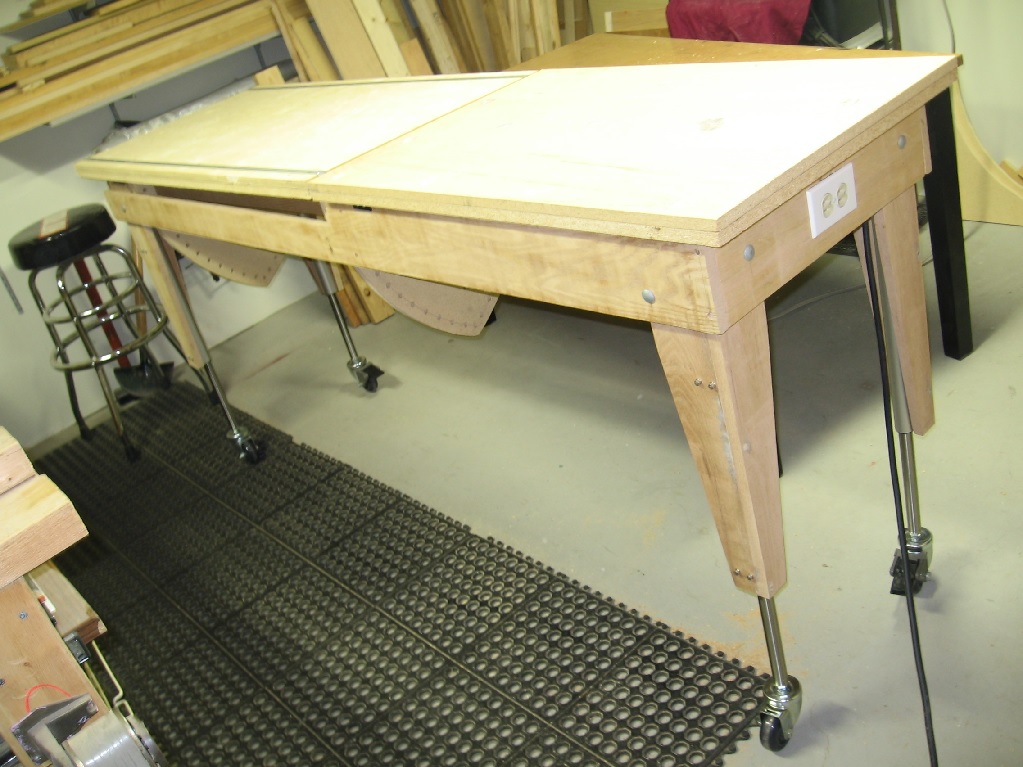
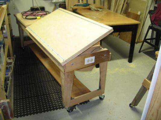
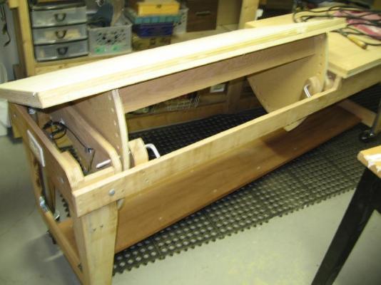
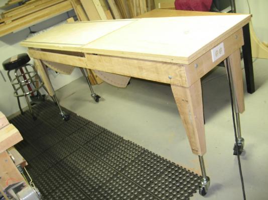
I managed to put in more time on my modeling table build and it is near done. (Pictures follow below) I installed the short cross braces at the bottom of the end legs These are held in place with screws and metal brackets below and above I then installed metal shelf hanging brackets (I had been saving these for years) Then built the shelf / long cross brace Cut the shelf and two stiffeners to length Marked off the location of the shelf bracket so the braces would be located just clear Chalked screw centre lines and outer edge of brace Clamped the brace to the shelf aligning it to the outer edge chalk line Drilled pilot holes, drilled countersunk holes and screwed in place Wood puttied the holes above the screw heads Installed the shelf and screwed to the bracket from underneath Installed the four pivot pin support brackets Cut my 3/8” diameter aluminium rod into 4 equal lengths Ground a radius edge on one end and taper on the other Bent a pull tab at 90° on the radius end about 1-1/2” long Installed the pivot table and tested it out … it didn’t work The holes were to tight and minor misalignment caused binding Opened up all the holes… yes all of them Now the pivot option works! Left to do… 1. Finish the table top edges 2. Paint 3. Final Clean up My breaking news: My darling wife saw my work spilling out of my play area and spreading all over the basement. She (who must be obeyed) suggested I need to enlarge my work room (don't have to tell me twice ... another project!!!... ????) Alan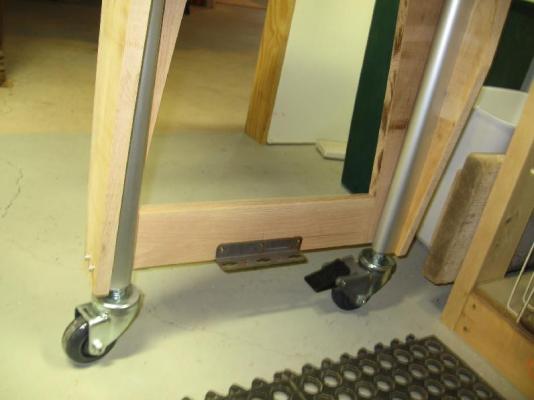


- 121 replies
-
- 12
-

-
what is the ideal modelling table?
AON replied to AON's topic in Modeling tools and Workshop Equipment
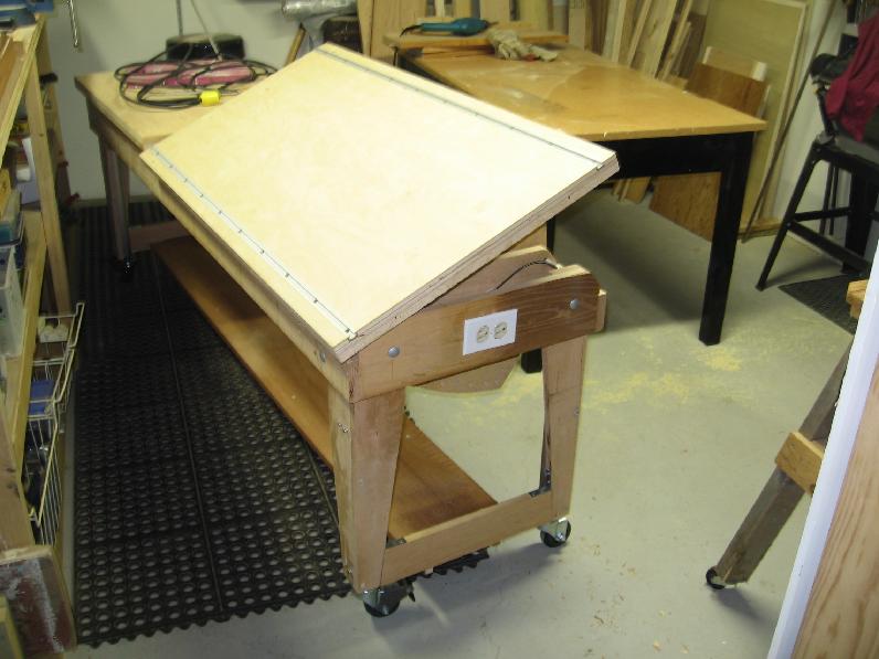
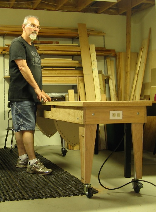
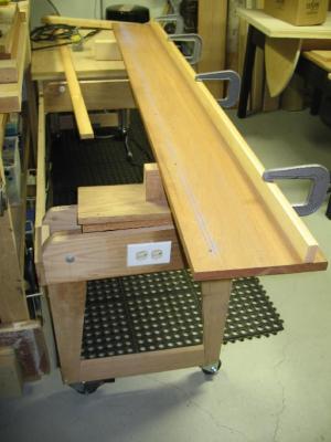
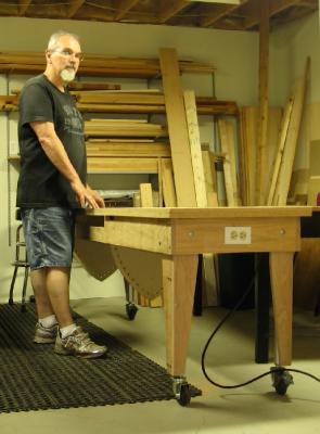
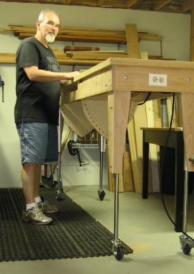
GOOD MORNING ALL! I will admit I was concerned about sturdiness of such a narrow (24") work table when raised so high but am happy to announce this table is much more sturdy and solid than I expected. Once I have the shelf on the bottom the centre of gravity will be lowered and it will be slightly better grounded yet. I had even pivoted the table with the pins inserted to get a feel for the usefulness of the feature and it gave me that warm and fuzzy feeling of a thing done right. Even if used only a few times it will be worth it to me. The "walk around" versus the "Lazy Suzan turn table" feature was a compromise for space and further expense. I am feeling good about this decision also but have not glued the top down so I can instigate plan B at any time in the future. The 3" wheels that were purchased with the lift glide extremely smooth and easy, absolutely effortless. I just need the lighting installed overhead. It also took awhile to settle on 24" x 48" for the build portion as I was going to go 18 or 20" x 36" but after reviewing build scales and the fact I didn't want to do this twice 24" x 48" seemed practical with regards to ergonomics (comfort and arm reach) This is all about comfort for me, storage of the build while under construction, storage of the wee bits and pieces between my visits. The size seems too large at the moment but if I go 1:48 scale (which I am really getting serious about) it will be perfect. As usual I am thinking ahead to a "tent cover" to keep the dust off the build. -
what is the ideal modelling table?
AON replied to AON's topic in Modeling tools and Workshop Equipment
sorry no orders once this is built I start my Billy Ruffian build -
what is the ideal modelling table?
AON replied to AON's topic in Modeling tools and Workshop Equipment
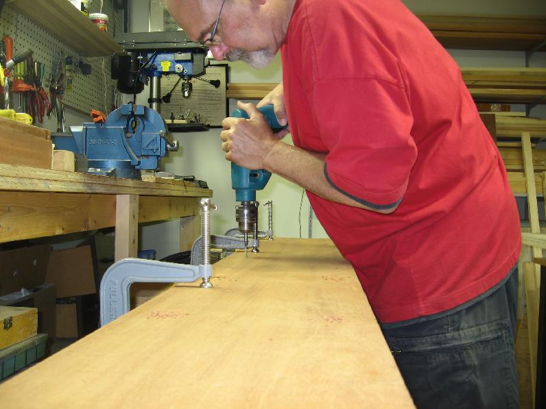
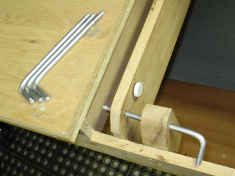
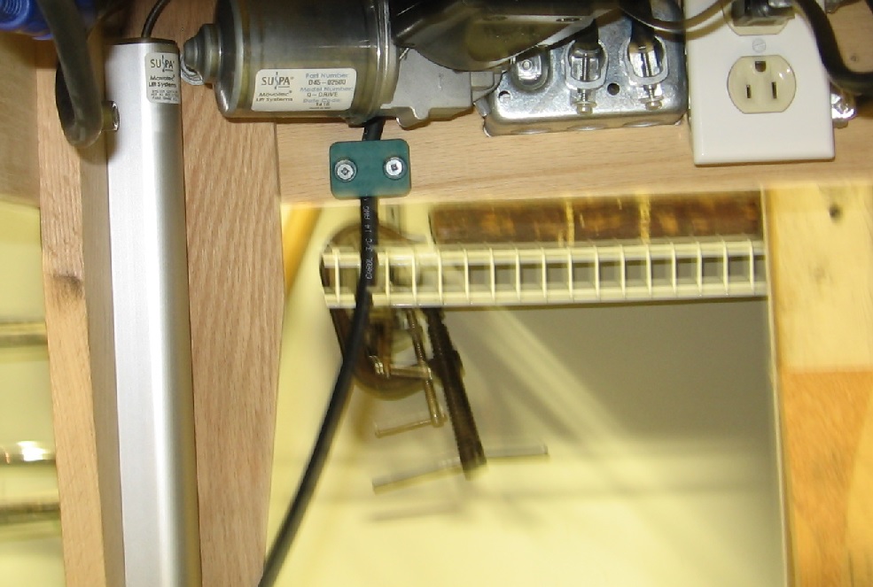
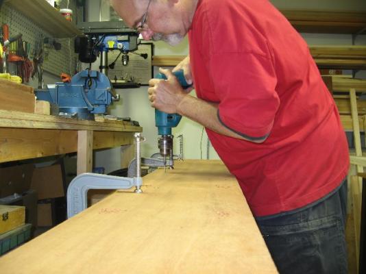
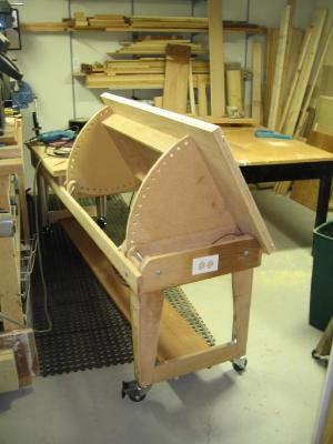
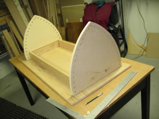
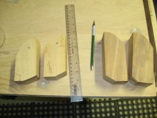
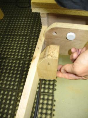
Did some more work on the table this weekend. Following is a description of the work and some photos 1. built frame work for the pivot table (picture of set up to drill dowel pin holes) 2. assembled the sub table top to the frame (drilled and screwed) 3. assembled the finished table top to the sub top (drilled and screwed) 4. applied wood putty to the screw holes 5. assembled the tracks to the table top (drilled and screwed) 6. assembled the pivot table to the table assembly, Temporarily inserted the pivot pins and... they would not assemble. Lifted the pivot table to take a look and the very first set of screws (step 2 above) went through the pivot pin holes, effectively blocking them. 7. take all the screws out of the top sheet (this meant digging out the wood putty). Remove the four offending screws and insert shorter screws. Check that they were indeed short enough. Reassemble the whole thing a second time. 8. cut out my primary pin support blocks (the pin goes through this block first then through the hole in the pivot plate, then through the hole in the frame. This way the 3/8" diameter aluminium pivot pin is supported both sides of the pivot plate) 9, added furniture button gliders (the white round button behind the block on the frame) onto the stationary frame so when the table is pivoted the wood will rub against the glider, not wood on wood) 9. I also added a strain relief to the electrical power cord (the green rectangular shaped box over the black power cord) Left to do: - complete the pin support blocks - assemble blocks to table frame - complete and assemble the pivot pins - add the leg cross bracing and shelf - painting

-
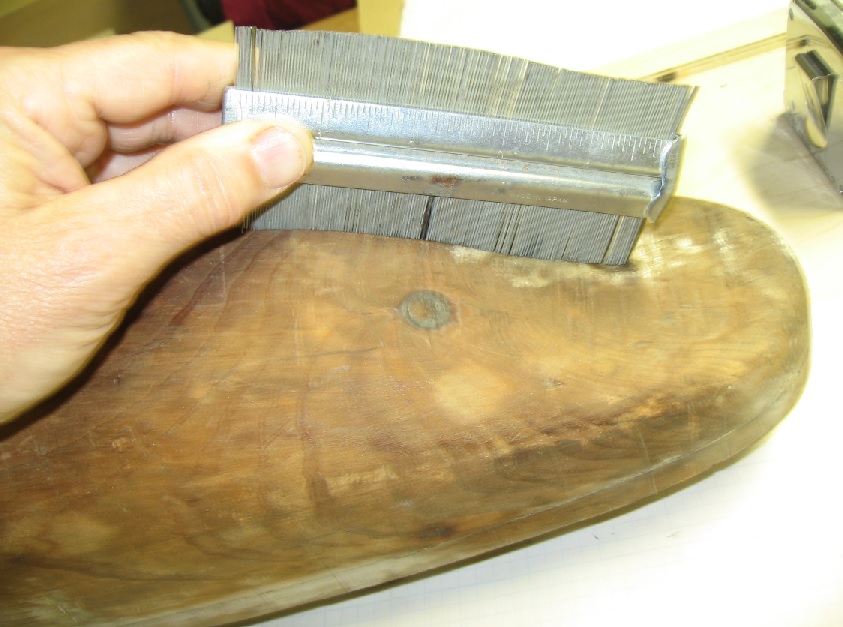
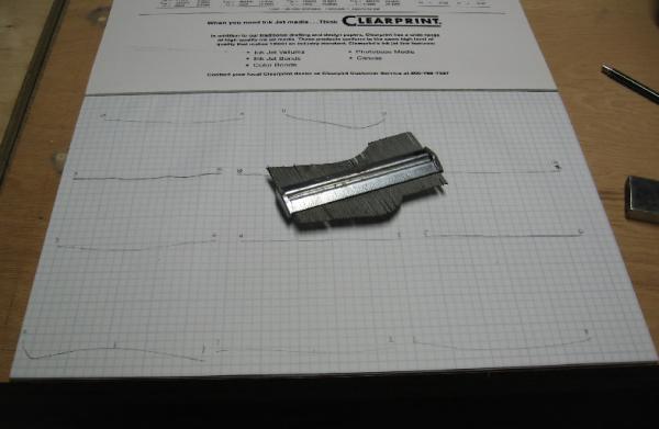
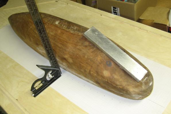
I managed to copy the underside shape of the hull onto paper and then cut and paste this to cardboard. The black mark on my profile gauge is the overlap I made on the profiles to assure everything aligned. I'll cut out the cardboard to make the template that will fit against the hull. I'll then trace the skeg profile I want to build onto to cardboard template. This will be fitted and adjusted to "look good". I'll then cut the shape from wood stock with my band saw and finally finish the shape with hand tools and a sander. Once fastened to the hull I will fill and blend the gaps with wood putty.

-
......... timing is everything .........
-
Thank you Bob. The measurements will help me scale my additions from any schooner photographs I might snag off the inter-web (including models here!) Alan
-
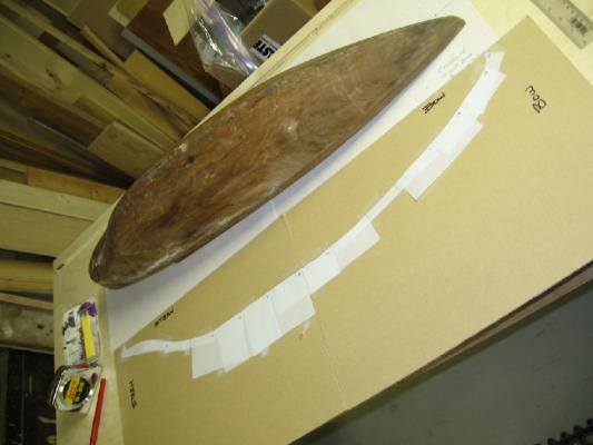
Here are the photos ... and yes that is my unfinished modelling table I am using The lift feature came in very handy! It is definitely going to get a lot of use 1. plotting the shape 2. chalking the centreline 3. drilling three tiny centreline holes 4. the plotted shape got to go time to work.


-
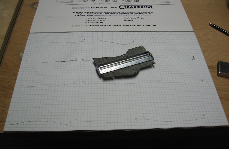
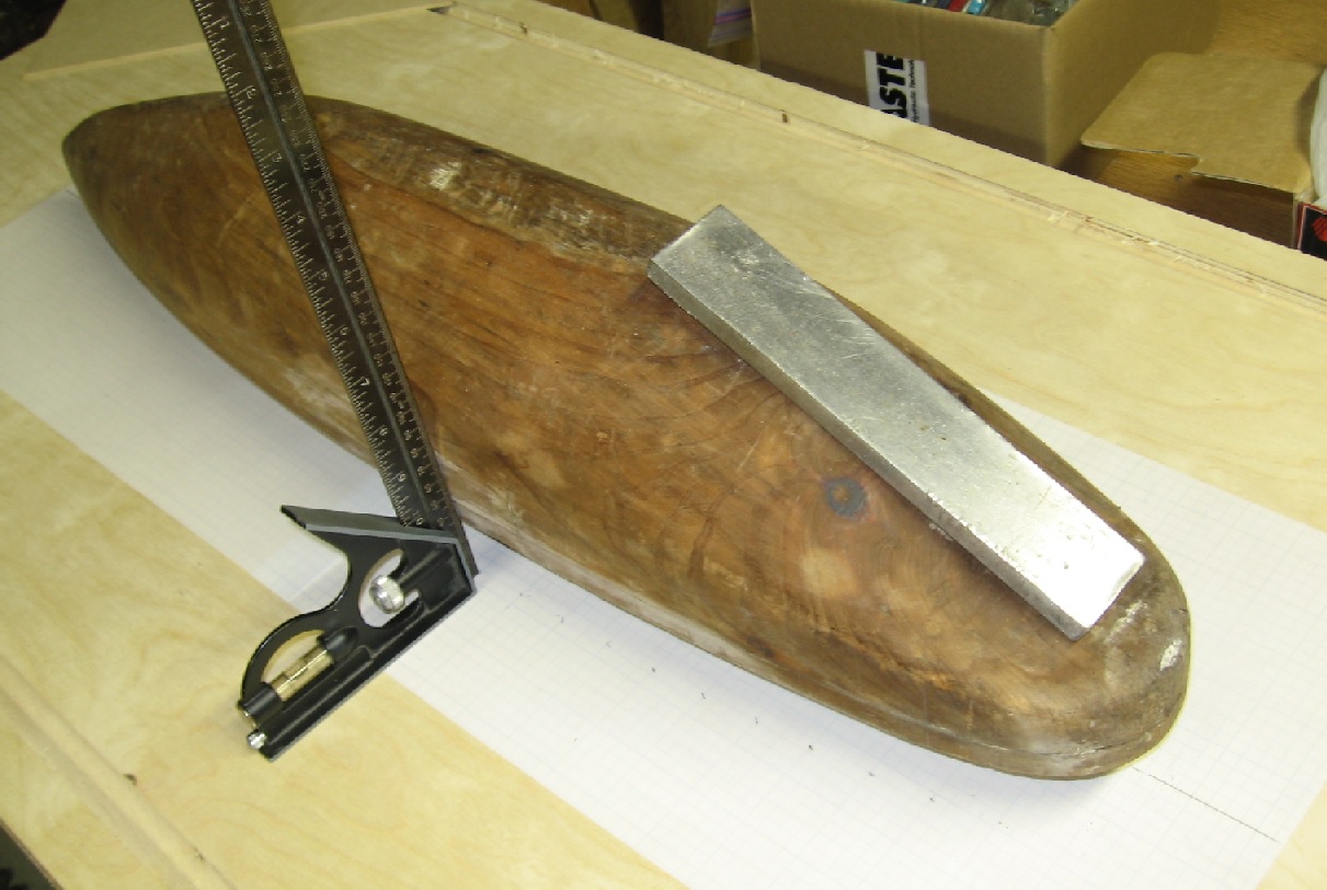
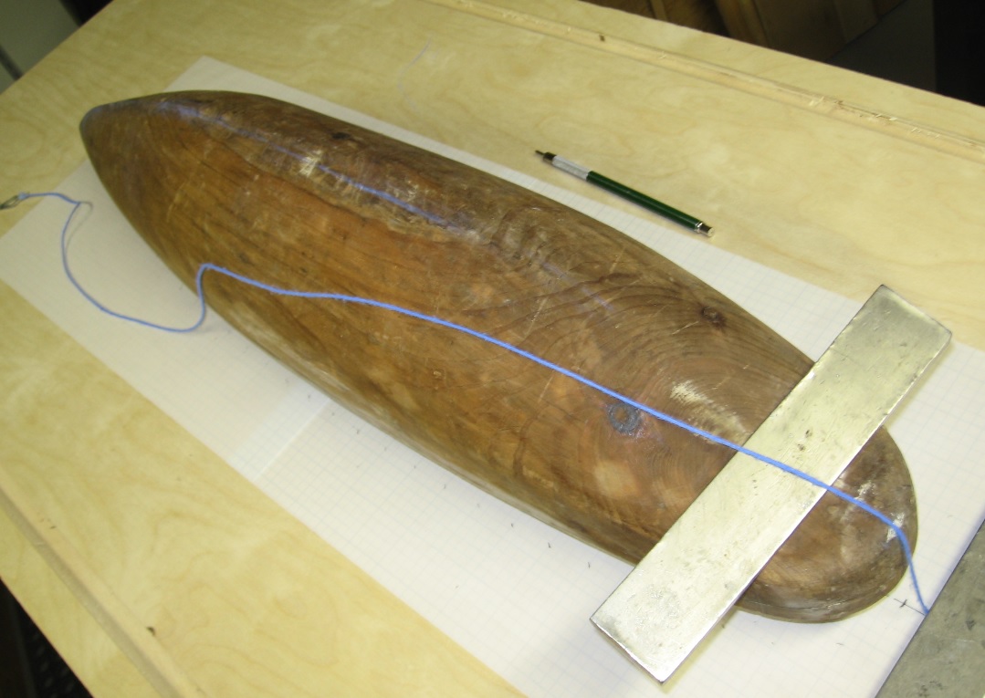
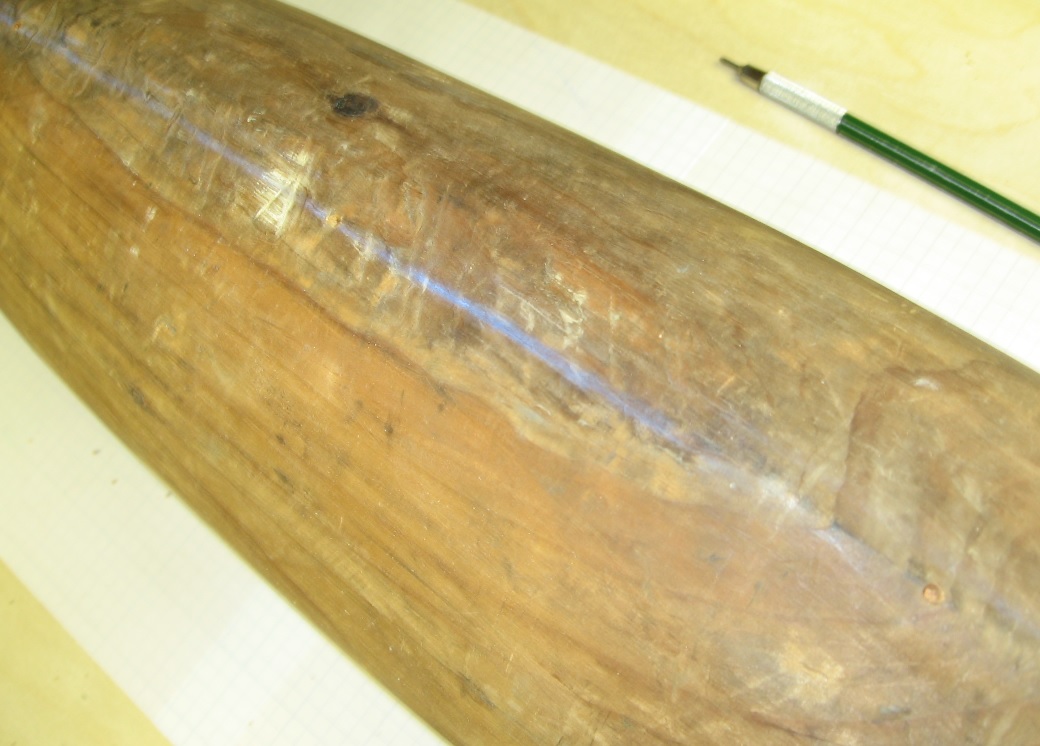
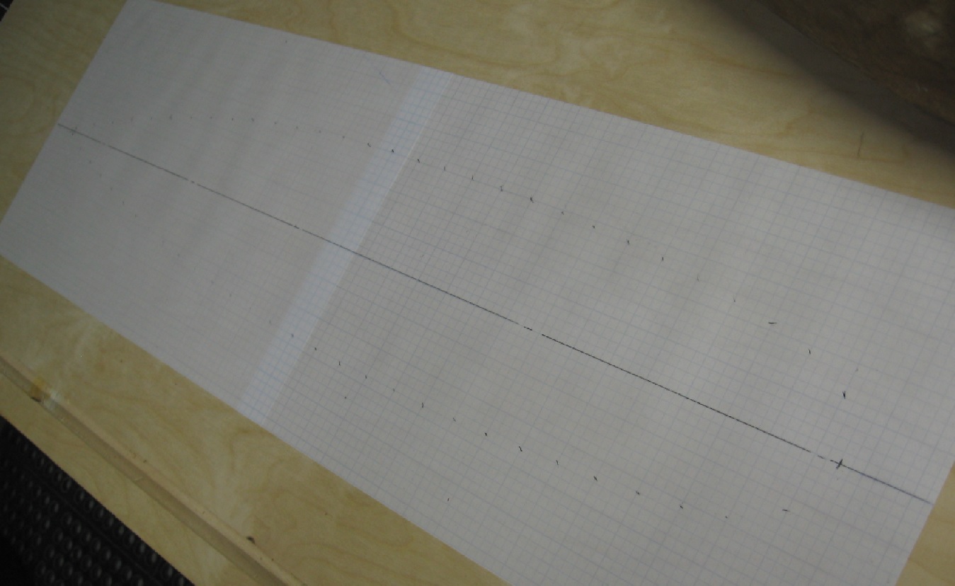
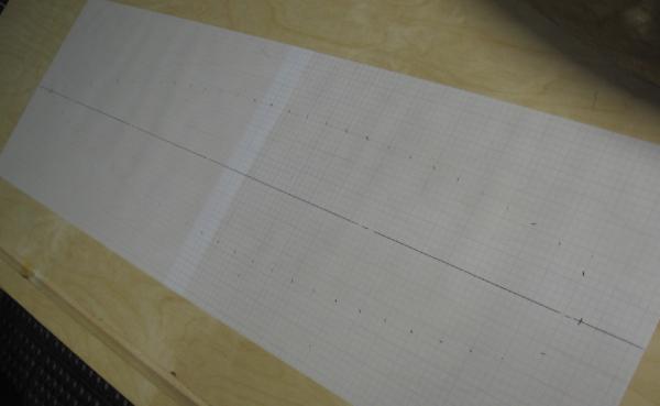
I set the hull upside down on graph paper and centred the stern to the bow using a square. I then marked reference (station?) lines at 1" intervals onto the hull and graph paper Now I have the top profile on paper and reference marks on the hull The model is 6-3/4" wide x 30-7/8" long (171 mm x 784 mm) I then got out my trusty chalk line and established a centreline along the bottom I drilled three tiny shallow holes on the chalk line as it will rub away This is my permanent (until covered) reference for the centreline My next step (tomorrow?) will be to use my profile gauge along the underside of the hull to trace the shape to transfer to a template. I did take some photos (to be posted later today) but have to get ready for my day job now. Hi Ho, Hi Ho, It's off to work I go............................