
Supplies of the Ship Modeler's Handbook are running out. Get your copy NOW before they are gone! Click on photo to order.
×


AON
-
Posts
2,791 -
Joined
-
Last visited
Reputation Activity
-

 AON got a reaction from SimonR in Hello from Ireland
Good evening Simon and welcome aboard!
Alan O'Neill
-
 AON got a reaction from mtaylor in Hello from Ireland
Good evening Simon and welcome aboard!
Alan O'Neill
-
 AON got a reaction from Edwardkenway in Hello from Ireland
Good evening Simon and welcome aboard!
Alan O'Neill
-
.jpg.d84ec4dad1d7791e855dca06210ab6f3.thumb.jpg.f45209242e851d4409eca1a09293165b.jpg) AON got a reaction from hollowneck in HMS Bellerophon 1786 by AON – scale 1:64 – 74-gun 3rd Rate Man of War - Arrogant-Class
AON got a reaction from hollowneck in HMS Bellerophon 1786 by AON – scale 1:64 – 74-gun 3rd Rate Man of War - Arrogant-Class
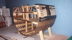
Well, I just today finished my one hole 16'-9" Aleutian hunting Baidarkas (Kayak) frame build.
Photo posted below for your amusement.
I will be writing this one up and submitting it for publication in the Nautical Research Journal.
My River Raft (above) was published in the issue that came out today.
Then I'll be back full time on my Billy Ruffian.
-
 AON got a reaction from Landlubber Mike in Are there any decent clamps?
Not to be funny... I find all clamps are very good until you need that special one... like right now.
-
 AON got a reaction from Old Collingwood in HMS Bellerophon 1786 by AON – scale 1:64 – 74-gun 3rd Rate Man of War - Arrogant-Class
Well, I just today finished my one hole 16'-9" Aleutian hunting Baidarkas (Kayak) frame build.
Photo posted below for your amusement.
I will be writing this one up and submitting it for publication in the Nautical Research Journal.
My River Raft (above) was published in the issue that came out today.
Then I'll be back full time on my Billy Ruffian.
-
 AON got a reaction from allanyed in Are there any decent clamps?
Not to be funny... I find all clamps are very good until you need that special one... like right now.
-
AON got a reaction from mtaylor in Are there any decent clamps?
Not to be funny... I find all clamps are very good until you need that special one... like right now.
-

 AON reacted to Ian_Grant in English flag
This comment made me think of Sheldon's "Fun With Flags" blog on "The Big Bang Theory". What a great show that was.
-
AON reacted to SimonR in Hello from Ireland
Hello everyone!
I joined a few weeks ago, and I will start a build log soon. Im starting out on a Sergal HMS President that I got as a Christmas present as my first build. Should be a bit of a challenge judging by the instructions! Currently half way through the first round of planking, its been quite the learning curve.
I have a background in Architecture, so I have experience in making architectural models, but I have already learned so much from model ship building, I wish I had started when I was in college as alot of the techniques I have learned so far would have been very useful for architectural model making. Great forum here, glad I found it, I have learned lots of tricks from you all.
Here is the progress so far. Getting a few of the smaller bits like anchors etc. while doing the planking.
Possibly not the best model to start out with, but I like a challenge
-
-
 AON reacted to Wintergreen in HMS Bellona 1760 by SJSoane - Scale 1:64 - English 74-gun - as designed
Hey guys, look up bitao7697s' setup for his Young America. I think that is @michael mott means.
-
-
AON reacted to toms10 in HMS Leopard by toms10 - FINISHED - 1:85 scale POF/POB
Hi everyone
Here is a little more sail work. I ended up going with the darker bolt ropes. There were cases for both light and dark. After making a couple small sails with the running rigging color I could barely see the rope on the sail. The color was too close to the sail. Including the cringles it was a lot of work that would basically go unnoticed. I leaned toward the more artistic side where the “ordinary” non-modeling person would appreciate the work. Neither one seemed to be wrong from the research I did.
Here is how I did the cringles. The head cringles is just a loop with a simple knot at the base to hold it firm. The leech cringles were done by piercing 2 holes first.
Second, the bolt rope was glued in place from the head down to the first cringle hole. From that point the bolt rope was just laid in place.
I then ran a 50 wt thread through the first hole with a very small sewing needle and tied a simple knot over the bolt rope to hold it in place and start the cringle. Repeat for the second hole.
I then took a straight dental pick and pushed it in between the sail edge and bolt rope to form the cringle. Then glued the bolt rope to the edge of the sail up to the next cringle hole and repeated the whole process for the next cringle.
I glued all the knots with Liquitex matte medium to hold them and allow me to trim them very close.
Here is a close up of the results. It is a bit tedious but I like the results and at 1:85 scale that is about as real as it is going to get; st least for the capabilities of this modeler. 😜
This may rank up there with tying rat lines!
Tom
-
AON got a reaction from mtaylor in HMS Bellona 1760 by SJSoane - Scale 1:64 - English 74-gun - as designed
You've put a lot more effort into your drawings then I have!
Should be fewer surprises.
BZ
-
AON reacted to druxey in HMS Bellona 1760 by SJSoane - Scale 1:64 - English 74-gun - as designed
Well the gun deck cannon issue is a serious one. And you wonder why so many models show the gun deck ports closed? One idea (thinking laterally); why not show the lids closed and display the armament for this deck on the model's baseboard? It has been done before; I recall at least one POW bone/ivory model in the Rogers' Collection with a similar presentation.
-
 AON got a reaction from druxey in HMS Bellona 1760 by SJSoane - Scale 1:64 - English 74-gun - as designed
You've put a lot more effort into your drawings then I have!
Should be fewer surprises.
BZ
-
AON reacted to SJSoane in HMS Bellona 1760 by SJSoane - Scale 1:64 - English 74-gun - as designed
Hi Alan,
Doing more drawing is how I procrastinate on actually cutting wood! It is becoming a bad habit...🙃
Mark
-
AON reacted to SJSoane in HMS Bellona 1760 by SJSoane - Scale 1:64 - English 74-gun - as designed
A couple more sheets. These are not yet really finished or laid out as final drawings, but they do help pull together a lot of work I have done on more detail. Just in case the electronic world fails, I will have hard copies of the basic information!
-
AON reacted to SJSoane in HMS Bellona 1760 by SJSoane - Scale 1:64 - English 74-gun - as designed
Hi druxey, I so wish I could take a jewelry class somewhere. I seen now how exceedingly helpful that would be. Silver soldering still eludes me...
Other things in life have taken me away from the shop. But while distracted by other things, it helped clarify my next steps, resolving the numerous chicken and egg issues of what has to come before what.
I have concluded that I cannot install the barrels of the guns on the gundeck afterwards. The stool bed and wedged quoin are way too delicate; several have broken off just picking up the carriages. I will need to epoxy the barrels both at the capsquares and at the quoin, possibly pinning somehow at the stool and quoin. So all of this has to happen before I start closing in the gundeck with the upper deck over it.
And once the cannon are sticking out (druxey, is that the official naval description?), I need to avoid putting the hull on its side or perhaps even upside down. So everything requiring turning the hull upside down or sideways needs to be completed before the cannon go in and I can start on the upper decks.
So, I first need to finish as much carpentry work as possible that will create shavings inboard, so I can tip the hull over and clean it out before proceeding. This means cutting all of the mortises for the beams on the upper deck, quarterdeck and forecastle, and roundhouse. Also, drilling the hawse holes.
Then I need to finish up the outboard work including planking as much as possible, so I can turn the hull on its sides for painting the wales and the cutwater at the stem. I also need to consider finishing more of the stern works, which will also require turning the hull upside down--particularly for the frieze painting on the lower counter.
Next step, then, cutting the beam mortises. Last time, I laboriously measured each beam location from the drawing, then measured from a station line on the hull. I had to square every beam up, to ensure they were parallel. This was complicated by the fact that many beams were asymmetrical due to the halved joint between the two parts. Each side was offset a little from the other side.
Now many years later, with CAD drawings available, I am planning to print the upper deck, glue it to some stiff card, and lay it on the beam shelves. Then I can simply mark the location of each beam for the mortise.
For the first time, I took electronic copies of my CAD drawings to the local UPS store, where they printed out very accurately dimensioned sheets on 30 X 42 inch paper. Doesn't look too bad, hate to cut up the sheet. But it was only $3 US per sheet, so I will go back for more.
Mark
-
AON reacted to toms10 in HMS Leopard by toms10 - FINISHED - 1:85 scale POF/POB
Hi Tom,
I do have that book and it has been a great help. Like you I am not a sailor and learning as I go. As you mentioned, I will not be doing anything regarding the studding sails. Those are stored in the sail room below. 😄 I am not sure what sails I am going to set. I may just take a a picture out of the Seamanship in the Age of Sail book or some other reference and duplicate it. Thanks for the help (I can use all I can get) and the kind words.
Hopefully we can see each other in New London at the joint conference in October.
Tom
-
AON reacted to TomShipModel in HMS Leopard by toms10 - FINISHED - 1:85 scale POF/POB
Your model is excellent. Since you are going to bend sails, a very good reference is "Seamanship in the Age of Sail" by John Harland. I am not a sailor, and this book will help you to enhance realism. For example, a ship like yours did have 37 total sails. However, they were never all set. The reason is that they would blanket each other and be counterproductive. So, stay sails would be set if a ship was sailing close to the wind. However, in that sitution some of the square sails would not be set and those that were would have their yards braced to the extreme. Also, studding sails were normally not set on both ends of the yard. They would be set on one side or the other and normally not bent at all. The only documented case of a ship having every sail set was when Constitution was becalmed when it was being chased by a British Squadron. The ship was being towed/kedged, in the hope of finding any wind. Once they did find some wind, only the sails that were favorable were left set.
Finally, many of the running rigging lines would actually hang with a drape. For example, if the courses are furled, both the sheets and tacks would be hanging slack.
I really appreciate your build and good fortune with your sails.
-
AON reacted to garyshipwright in HMS Montague 1779 by garyshipwright - 74-gun Alfred-class
Hi Clay. Well good sir my thought process on the framing was I used butt's to hold the parts of the frame together that is shown on page 18 in Goodwin's book. Being a expert , thank you for that, but call my self more of a student who will never finish school. When i started building my frames I did use chocks to hold the parts together but being that you make about a 130 frames it takes awhile which is why I used the butt and dowel that hold's those parts together. Not as time consuming and once the planks are installed on the outside and inside you can't see the chocks but if I had to do it again I would have installed the chocks, but today that is just a bit of hind sight on my part. Installing the chocks does take a while and after three years of framing figure chocks would have added 2 years to their building, for me anyway. Chock's would be more accurate doing our time frame. Now the sister frames would have been called bends and it seems that He shows this on page 14,16 and 18. What they usually did, as far as I can tell in Alfred's/Warrior time frame, would be to to build one bend( two frames put together as one) two single filling frames that did not touch each other and then another bend. Some where around the dead flat there was a changing of the floors so at that place you would have a floor, a first futtock and then another floor. What they did is at the forward part of the hull the floors would be on forward side and aft the would be on the aft side. I added a photo of Alfred's framing plan and my framing , they are about as close as I can get them. If you look at station 1 and the dead flat you will see the switching of the floor. How you can tell is that there is three filling frames between the two bend's and usually you only had two filler's. Now the bend's didn't touch as the went up but was pushed apart with blocks of wood , so the upper parts of the frame's could make up the side of the gun port. Those parts of the frame were bolted together were the blocks were installed . I colored those blocks black and shows that this was a station and the filling frames did not have those blocks. Hope this makes sense Clay. Gary
-
AON reacted to toms10 in HMS Leopard by toms10 - FINISHED - 1:85 scale POF/POB
Just bought the NRG Shop Notes Volume 2. If I like them then volume 1 will be a great gift idea for somebody 😜😁. Now if I could just get the admiral to read this post ....
Tom
-
AON reacted to TomShipModel in HMS Leopard by toms10 - FINISHED - 1:85 scale POF/POB
Good morning. I did silk span sails for my 1:96 HMS Liverpool. I used silk span as it can be draped, furled, and billowed very easily using dilute white glue with a touch of biocide in the mix to prevent mildew. I use three plies and laminate them together. The center plie has the tabling penciled on. Up to 1:48, this should work well. This method has been demonstrated many times and was put in NRG Ship Model Shop Notes 2. The results are very good. I modifi ed the method slightly to suit my model. I've presen ted this method several times at our local clubs. Here is a photo of the results.