


wefalck
-
Posts
6,358 -
Joined
-
Last visited


.thumb.jpeg.fc5d633a7b34428fcf19419a73d56d55.jpeg)


-
 Bob Cleek reacted to a post in a topic:
Pretty cool tool: drilling positioner
Bob Cleek reacted to a post in a topic:
Pretty cool tool: drilling positioner
-
 Ras Ambrioso reacted to a post in a topic:
Pomeranian Rahschlup 1846 by wefalck – 1/160 scale – single-masted Baltic trading vessel
Ras Ambrioso reacted to a post in a topic:
Pomeranian Rahschlup 1846 by wefalck – 1/160 scale – single-masted Baltic trading vessel
-
Marcus.K. reacted to a post in a topic:
Pomeranian Rahschlup 1846 by wefalck – 1/160 scale – single-masted Baltic trading vessel
-
Keith Black reacted to a post in a topic:
St Roch by Lecrenb - 1:48 scale - RCMP Schooner rigged as schooner c. 1930/35
-
 Look for a building log on the Norwegian GJØA, I seem to remember that she used a chain drive from a petrol engine to the spill/winch.
 -
Paul Le Wol reacted to a post in a topic:
St Roch by Lecrenb - 1:48 scale - RCMP Schooner rigged as schooner c. 1930/35
-
druxey reacted to a post in a topic:
Libertad 1925 by Valeriy V - Scale 1:100 - Spanish Type F Light Cruiser
-
druxey reacted to a post in a topic:
St Roch by Lecrenb - 1:48 scale - RCMP Schooner rigged as schooner c. 1930/35
-
Paul Le Wol reacted to a post in a topic:
Libertad 1925 by Valeriy V - Scale 1:100 - Spanish Type F Light Cruiser
-
Keith Black reacted to a post in a topic:
Libertad 1925 by Valeriy V - Scale 1:100 - Spanish Type F Light Cruiser
-
Keith Black reacted to a post in a topic:
Hercules by vaddoc - 1:64 - Steam Tugboat
-
Excellent metal work as usual. What do you use as heat-sink to prevent parts already soldered from falling apart?
-
wefalck reacted to a post in a topic:
Libertad 1925 by Valeriy V - Scale 1:100 - Spanish Type F Light Cruiser
-
Yes, some of the tugs did have indeed rather sleek hulls. How will you simulate the plating?
-
wefalck reacted to a post in a topic:
Hercules by vaddoc - 1:64 - Steam Tugboat
-
I think that it would have been a chain-drive. Leather belts would break, if humid and frozen. I have never seen belt-drives on ships, but chain-drives seem to have been fairly common at a time before electrical direct drives became the norm.
-
wefalck reacted to a post in a topic:
Pelican 1943 by FriedClams - 1:48 - Eastern-Rig Dragger
-
wefalck reacted to a post in a topic:
HDMS Elben 1831 by TJM - scale 1:64 - PoB - first scratch build
-
wefalck reacted to a post in a topic:
Lancha Chilota by JacquesCousteau – Scale 1:32 – Chilean Coasting Sloop
-
wefalck reacted to a post in a topic:
Lancha Chilota by JacquesCousteau – Scale 1:32 – Chilean Coasting Sloop
-
Glad to have been of service ... As to the robands vs. continous lacing, I have seen both used on the same sail. I didn't check on the photographs, but was the foot of the sail actually tied to the boom? On vernacular craft sails were often loose-footed, as this allowed tricing them up quickly and thus take the pressure out of a sail e.g. in an emergency. Whether and how a sail was tied to the boom may also be depending on whether the boom was used as a cargo derrick. Robands may be easier to untie than to unravel a continuous lacing.
- 281 replies
-
- 4
-
-

-
- Chile
- Latin America
- (and 5 more)
-
wefalck reacted to a post in a topic:
Lancha Chilota by JacquesCousteau – Scale 1:32 – Chilean Coasting Sloop
-
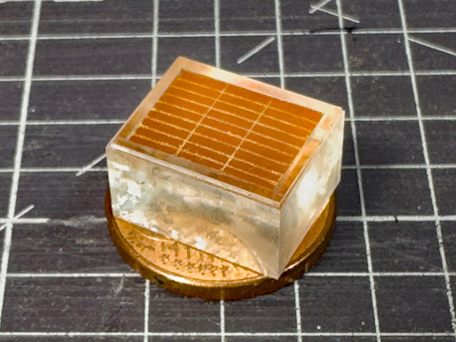
In spite of a week's travel for business, I managed to get done a part: ********************* The Main Hatch The main hatch will be shown closed, so I could revert to my usual technique of milling it from a solid piece of acrylic glass. In fact, the piece forms a core and as sharp corners for the recess into which the hatch covers fit is needed, around it strips of 1 mm acrylic glass were cemented. This arrangement was milled to size and shape as shown previously. To make it visually more interesting a quarter-round cove was milled into the outer edge with a 0.5 mm ball-burr. In real life, this would also prevent the wood from splintering, when hit by something during loading. Milling a quarter-round cove into the coaming of the main-hatch The cover was assumed to be in three parts, each planked with short lengths of plank. The cover is made from a tight-fitting piece of bakelite paper into which the planks were engraved, as was done for the deck-planks. Making hatch and cover in separate pieces allows to paint it with sharp edges. The cover will be simulated to be natural wood. The main-hatch with the cover inserted Eventually, the hatch will be fitted with clamps for the battens to tie-down the canvas cover. That will be done at a later stage to avoid damage during fitting the part into the deck. To be continued …
-
wefalck reacted to a post in a topic:
J H Crawford by LJP (Lawrence Paplham) - Scale 1:64 - an 1894 to 1898 Wisconsin sternwheeler
-
wefalck reacted to a post in a topic:
J H Crawford by LJP (Lawrence Paplham) - Scale 1:64 - an 1894 to 1898 Wisconsin sternwheeler
-
Keep in mind that they have been painted decades later …
-
In any case, don't iron sails already treated with acrylic paint. The paint is not heat resistant. Otherwise, I ironed silk-paper slightly humid with a wool seeting or so between two thin cotton towels. Keep the iron moving, it is easy to 'brown' the paper ...
-
Pretty cool tool: drilling positioner
wefalck replied to CPDDET's topic in Modeling tools and Workshop Equipment
The problem is, that it only works for the set of diameters provide in the tool ... -
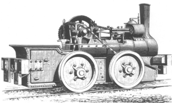
Aveling & Porter converted a couple of their traction engines for use on rails in the RN Dockyards. There is a preserved one in Chatham: https://newsite.dockyardrailway.co.uk/?page_id=89. The wheels are driven by chain from the crankshaft.
-
Well, I did not contemplate to etch the bars, but rather to etch notches into the back of the frames to allow to glue in the wires at correct and equal spacing, as I had done for the engine-room skylight of SMS WESPE.
-
Machining bevel gears it not trivial and one needs a pretty massive 'universal' milling machine or shaper and a dividing head for that. However, by 1900 it would not be uncommon to see bevel gears of some sort on steam-engines. For instance, they were used since the later 1860s or so to drive the rope-drums on ploughing engines. Also, they became increasingly common in engineering due to the budding automotive sector, although there initially chain-drives were used. Chain-drives were used on (sailing) ships for instance to power winches from a centrally placed IC engine, but also in stationary industrial applications powered by steam. From the modelling perspective, one could turn a cone and file the teeth for bevel gears. You can buy them down to 0.3 modular, but that would be still too coarse for your scale. For chains, one could try to find a so-called fusee-chain as used in certain types of clocks/watches, but I have no idea of prices.
-
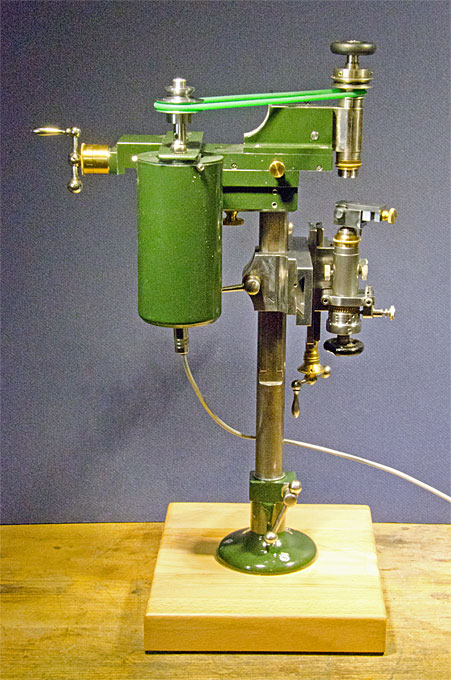
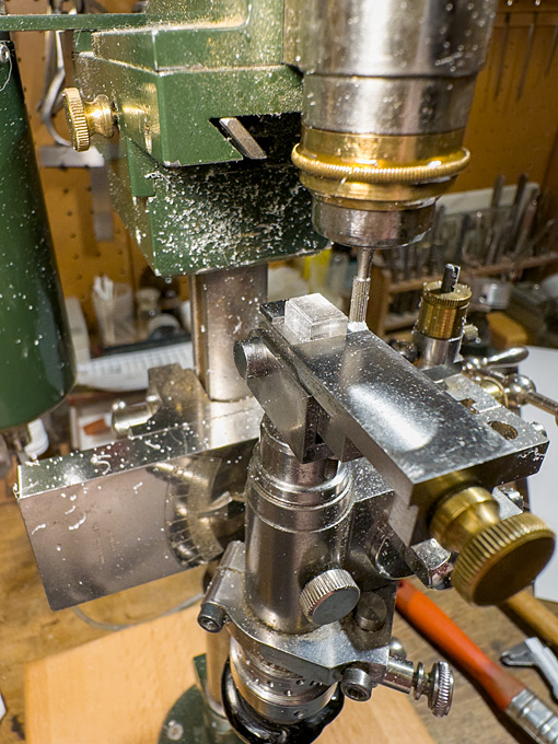
Well, it's a vintage milling machine that never was: https://www.maritima-et-mechanika.org/tools/micromill/micromill.html. The key mechanical parts came from antique watchmaking lathes. https://www.maritima-et-mechanika.org/tools/micromill/MF-V1.mp4 The miniature vice is shop-made: https://www.maritima-et-mechanika.org/tools/attachments/attachments.html#Micro_vice
-
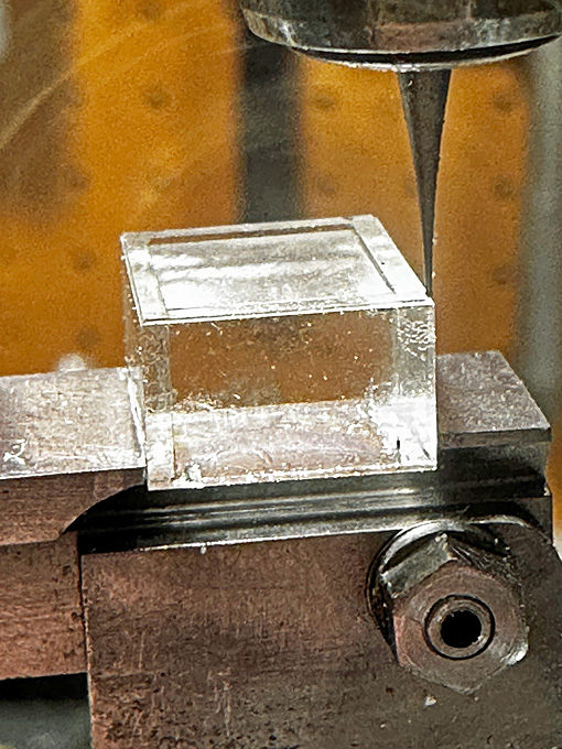
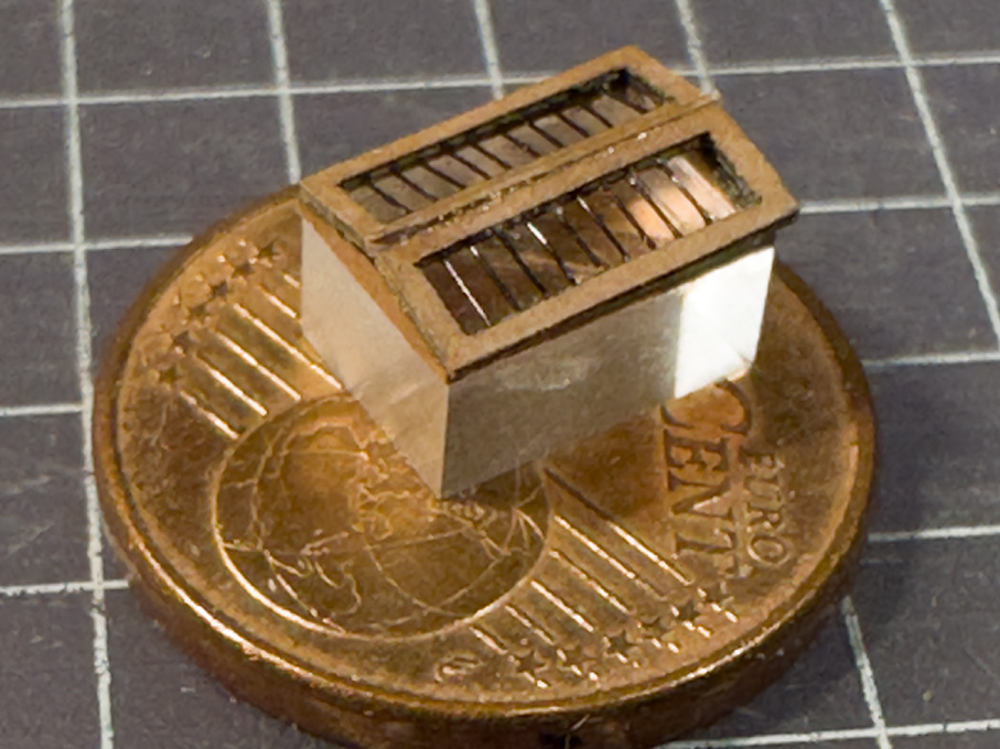
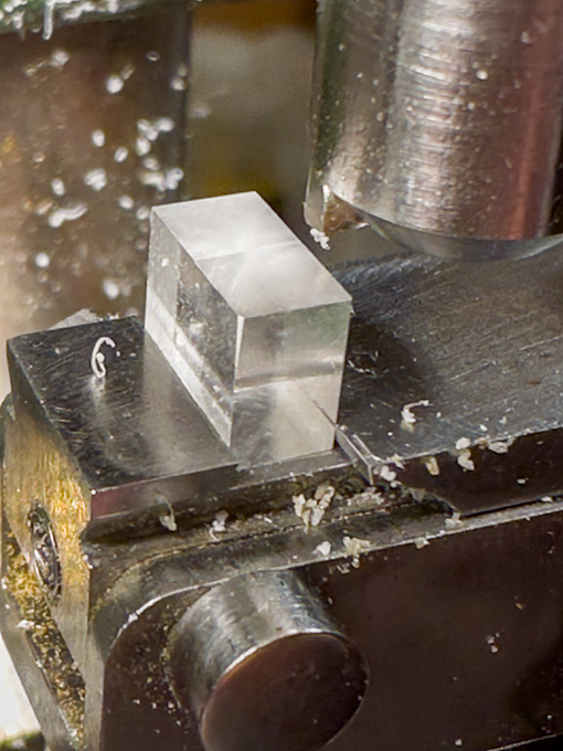
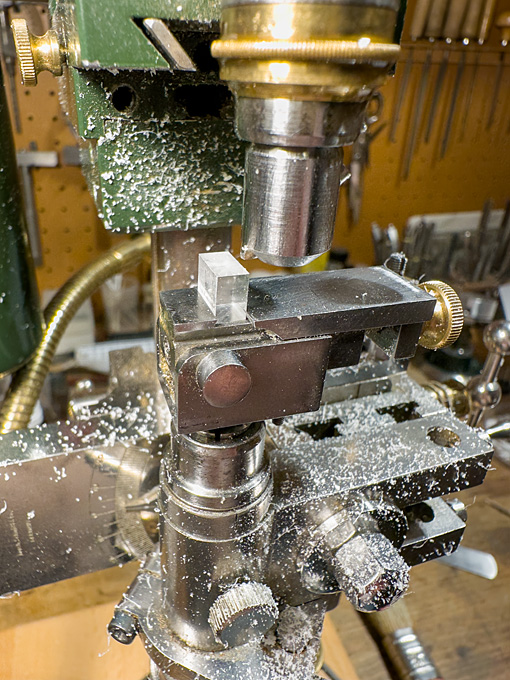
In between business-related absences from home, I managed to progress a little bit ... **************** Cabin Skylight As noted previously, the cabin skylight is a somewhat perilous position, but nevertheless contemporary drawings and some old models indicated, that they were of relatively lightweight construction. The actual construction is somewhat conjectural, but it seems that the hatch was covered by frame into which glass-panes were insert. Over this, there is a shallow roof-like structure with protective iron bars. In this arrangement, the glass-panes are not actually insert into the roof-like structure, but are at some distance below. The effect is, that even in the event that the iron bars are bent, the glass would not be touched. It also conceivable, that in the Baltic not real glass was used, but rather muscovite, which would be obtained by trade from Russia. In the event of very bad weather, the roof-like grille presumably could be replaced by a plain hatch cover. Milling to shape of the acrylic glass core for the cabin skylight This structure was built up in my preferred way, that is around a core of acrylic glass. It was milled to size from scrap piece of acrylic glass. For the ‘glass’ surface, I was able to use one of the original - as manufactured - surfaces, so no polishing was required. The high-speed milling with a fly-cutter a low feed-rate left almost transparent surfaces. Milling to shape of the acrylic glass core for the cabin skylight Milling of the recesses for the laser-cut frame parts The parts for the roof-like structure were produced again with the laser-cutter from Canson paper. The structure was to be designed in two parts, namely the frame attached to acrylic core and the two roof halves with the grilles, to allow painting. During painting the horizontal pane will be masked off and the roof halves painted separately. In order to ensure equal spacing of the ‘bars’, the roof was built up from three layers with the middle layers having notches. This layer was lacquered onto one of the outer layers and the ‘bars’ attached with drops of varnish – quite a fiddly bit of work and I am not entirely satisfied with the result. In the past, I made such parts from surface-etched brass and this seems to have worked better, but I didn’t want to set up everything for etching just a couple of small parts. Basic structure of the skylight, waiting to be painted and finally assembled I prefer to defer painting to the late stages of the building process in order to avoid handling the painted parts as much as possible, so construction of the skylight stops here for the moment. To be continued …
-
You mean by drive-shaft and bevel gears?