
MORE HANDBOOKS ARE ON THEIR WAY! We will let you know when they get here.
×


Chuck
-
Posts
9,598 -
Joined
-
Last visited


.jpg.d84ec4dad1d7791e855dca06210ab6f3.thumb.jpg.f45209242e851d4409eca1a09293165b.jpg)
About Chuck

Recent Profile Visitors
49,967 profile views


-

question about waxing thread
Chuck replied to ford34tom@comcast.net's topic in Masting, rigging and sails
I dont use wax ever. My rope doesnt need it at all. It just obscures the detail of the rope and attracts dust which sticks to it like a magnet. Unless your rope is a fuzzy mess. Dont use it. Instead, run your rope through a alcohol flame rather than a candle flame because it wont leave soot. That gets rid of the fuzzies. But never wax. Best thing to do is buy better rope. No stretching, wetting or waxing needed. Just use it out of the package. Rope of Scale or Syren makes perfect rope. You just have to pick the one that you like better because the color tan and brown is slightly different from both sources. Chuck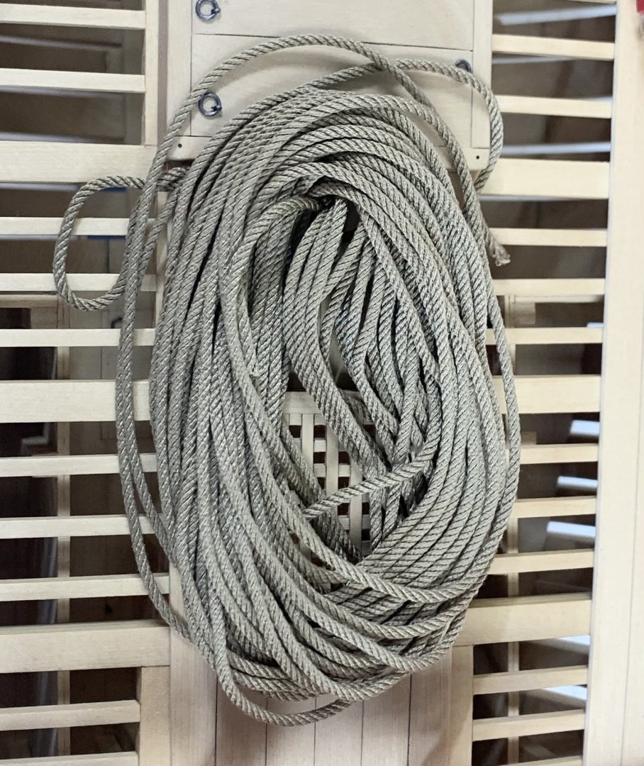
-
 Chuck reacted to a post in a topic:
Syren Ship Model Company News, Updates and Info.....(part 2)
Chuck reacted to a post in a topic:
Syren Ship Model Company News, Updates and Info.....(part 2)
-
Chuck reacted to a post in a topic:
Syren Ship Model Company News, Updates and Info.....(part 2)
-
dvm27 reacted to a post in a topic:
Syren Ship Model Company News, Updates and Info.....(part 2)
-
druxey reacted to a post in a topic:
Syren Ship Model Company News, Updates and Info.....(part 2)
-
Rustyj reacted to a post in a topic:
Syren Ship Model Company News, Updates and Info.....(part 2)
-
RLK reacted to a post in a topic:
Syren Ship Model Company News, Updates and Info.....(part 2)
-
Nunnehi (Don) reacted to a post in a topic:
Syren Ship Model Company News, Updates and Info.....(part 2)
-
Ryland Craze reacted to a post in a topic:
Syren Ship Model Company News, Updates and Info.....(part 2)
-
Tossedman reacted to a post in a topic:
Syren Ship Model Company News, Updates and Info.....(part 2)
-
Tossedman reacted to a post in a topic:
Syren Ship Model Company News, Updates and Info.....(part 2)
-
CiscoH reacted to a post in a topic:
Syren Ship Model Company News, Updates and Info.....(part 2)
-
Archi reacted to a post in a topic:
Syren Ship Model Company News, Updates and Info.....(part 2)
-
Chuck reacted to a post in a topic:
HM Gun Brig Adder 1797 by Geordie Tyne - Vanguard Models - 1:64
-
Chuck reacted to a post in a topic:
HMS Portland 1770 by scrubbyj427 - 1:48 - 4th rate 50-gun ship
-
Thanks guys for saying. I am quite happy with the finish and color. Chuck
-
Chuck reacted to a post in a topic:
Syren Ship Model Company News, Updates and Info.....(part 2)
-
Chuck reacted to a post in a topic:
Syren Ship Model Company News, Updates and Info.....(part 2)
-
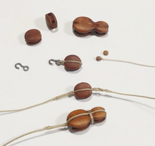
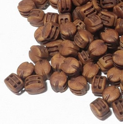
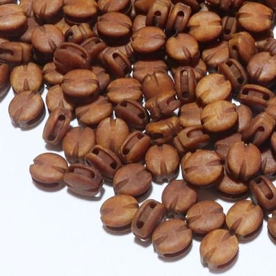
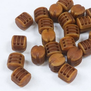
After a weekend of busy sales...rest assured I should be restocked with blocks by tomorrow afternoon....You guys must be building a lot of ship models. Actually finishing up more 2mm single blocks as I write this. Then onto rope.
-
Lovely work Chris.
-
Chuck reacted to a post in a topic:
La Renommee 1744 by ChrisLBren - 1/48 - 2025
-
Chuck reacted to a post in a topic:
HMS Portland 1770 by Trussben - Portland Scale Ship Co. - 1:48 - 50 gun 4th rate
-
Chuck reacted to a post in a topic:
Swan Class Sloops Plans Set
-
Oh my!!! That was sure some kind of machine, LOL. The plans are still out there if you can get parts. Google it!!!
-
You could easily use the Model Shipways ropewalk. Its flimsy and pricey for what you get but at $50 it will do the trick for just your own model. My more robust version of a ropewalk will hopefully be back soon and it is also easy to make your own. I used the MS ropewalk for years before I went into the rope making business. Chuck
-
As it seems many of you noticed, I opened the store yesterday around 3pm. Its all going quick...at this pace in another day or two it will be all gone again. I am very thankful as always. But I wont shut the store down again. Whenever I get around to restocking the items I will get around to it. Its just too much....so it will get done eventually. Sorry in advance for the wait times. Its gonna be a slog. Chuck
-
Actually my head stock and tail stock are 43 feet apart when I make my 30 foot lengths of rope. You were pretty close. LOL
-
Ok let me get this other group going for the capstan first and once I get caught up and running smooth with store again. Chuck
-
Yours would be just as good really. Its kind of hard to make bad rope actually once you get the feel for it. I think I mentioned this once before, we had a blackout a few years back and I was still able to make rope in complete darkness by feel. Once you learn it is absolutely like riding a bike. I think it took me slightly longer, LOL....maybe 8 minutes per package rather than 7, LOL.
-
Not at all. You dont have to make 30 foot lengths. You could easily make a 12 foot length on demand when you need it in about 10 minutes or less. Is it a luxury to have more space to make longer lengths....absolutely. But the beauty of some rope walks is the ability to make ropes of any length or thickness on demand. When I was making rope for just myself, I made 12 foot lengths. When I opened the store I started making 20 ft lengths and then increased that again to 30 ft for the same price to give folks more product for the same $$. So it was very economical for people to buy way more than they actually needed. But making it on your own, your costs will only be for the ropewalk and for the materials. The material cost is ridiculously low. Its the labor costs you guys are paying for. You can buy one spool of Guttermann Mara thread for $4.50 From that one spool of thread you can make 15 packages of .025 tan rope 30 feet long. Its all just the labor costs. So it is well worth giving it a try and even making shorter lengths. Chuck
-
Glenn, I dont think so. In this particular case, I think there was just an unfounded rumor floating around that I was retiring and shutting down the shop. That is far from the truth. I will repeat that I am going to be around for a whole bunch more years. Only two things will make me shut down earlier , I drop dead, or I hit the numbers. So there is no need for hoarding and I think folks will realize that when they see things stay the same once I reopen. But I will revamp my effort to teach and encourage folks to make rope on their own. I will make more video tutorials and even maybe a workshop or group project of some sort. I might possibly release my plans and files for my ropewalk and we could have a group build. You could make it without a laser cutter. I could work up a material list and the sources to buy the stuff needed. Would you guys be interested in that? Glenn I am curious...have you ever tried making your own? You would be good at it. You get to pick your own material and the color and even the infinite number of sizes you would be able to make. More than any store could sell. And make rope on demand the moment you need it. Chuck
-
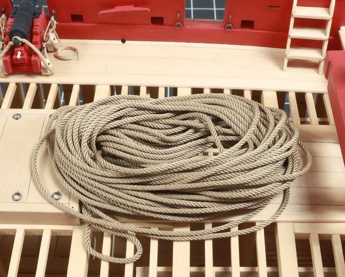
That is an option but for now I am good. I will just do my best and if folks have to wait a little bit for me to restock once in a while then hopefully it will be worth the wait. I used to have help with rope making but my son in law has moved on to other things. Ropewalks may be back in stock soon as well so hopefully more folks will try and make their own. They really should try it. Making rope for just one project you are working on, at the moment when you need it is just too easy...it takes less time than waiting for the mailman to deliver the stuff you buy from me or anyone else. This 30 foot length of rope literally took me 7 minutes to make and its perfect. Its only when you have to make 2500 feet of rope per day...every day... that it makes you want to stick a fork in your eye. Chuck

-
Thank God!!! I am on my last size of rope for restocking... Shouldnt be long now.
-
Lovely....so elegant!!!


