wrkempson
-
Posts
288 -
Joined
-
Last visited
Content Type
Profiles
Forums
Gallery
Events
Everything posted by wrkempson
-
This is new to me as well. According to the Online Etymology Dictionary the term "staircase" appears in the 1620's in reference to the enclosure of the stairs. I know we are looking at a contracts 150 years later, but it seems to me the nautical "staircase" or "stair case" or "stair-case" might refer to iron railings, hand rails, etc. that might surround (encase) the ladders. So my vote goes to staircase=handrails. In support I note that this section of the contract comes far distant from where the storage rooms would be described, lying between the office cabins and the pantries. Thus, the use of iron for casing the ladders would be of a more ornamental nature. This is pure speculation. Wayne
-
Lines Plans
wrkempson replied to ToddM's topic in Building, Framing, Planking and plating a ships hull and deck
Dropping perpendiculars from the half breadth plan to the sheer plan identifies the darkest lines as the rail line, as you surmised. A few waterlines run outside this line because of the slight tumblehome. The diagonals generally run wider. The confusion at the bow seems (to me) to be the result of careless drawing. I'm not sure about the confusion at the stern. At least, this is my less than expert take on things. Wayne -
Ed, I'm pretty sure that renegade eye bolt came from my work table. It was lost some time ago. I thought it had vanished into thin air, but now I know it fell through a space warp into your CAD program. Wayne
- 3,596 replies
-
- 3
-

-
- young america
- clipper
- (and 1 more)
-
Swan class 3D model in progress
wrkempson replied to dvm27's topic in CAD and 3D Modelling/Drafting Plans with Software
Astounding model. Thank you for the renderings. May I ask what software is being used and, if not too personal, what are the specs on the computer employed? Wayne- 104 replies
-
- 3
-
-
- pof swan series
- swan
- (and 1 more)
-
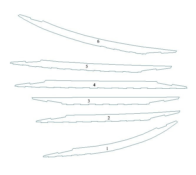
I am interested to know if you have taken the scarph arrangements from your plans. In a brief review last night, it seems that the scarphs were not usually drawn in. For Euryalus they were drawn in. I am attaching the keelson pieces from Euryalus that indicates the orientation of the scarphs. I could never make a great deal of sense out of it. The only thing I could come up with was that the keelson pieces were installed in the order 4,5,6,1,2,3. This would allow two gangs to fit the pieces in situ (4&1, 2&5, 6&3 being done simultaneously). Your arrangement, of course, would install 1,2,3,4,5,6. This is no big deal, but I thought I would mention it in passing. Wayne
-
Stage Coach 1848 by Eddie - Artesania Latina - Scale 1:10
wrkempson replied to Eddie's topic in Non-ship/categorised builds
I look forward to your progress. It looks like an exciting project. One very small thing. The box shows two pins at the ends of the spokes set into the felloes. I don't believe these are at all right. There are no pins or fasteners in the wheel. Everything was held together by the iron tyre (rim). If you consult photographs you should see there are no such pins. I feel like I am being more dogmatic than I should, so I am open to correction and reproof. Thanks for letting us look over your shoulder while building. Wayne -
Yet Another Pandora 3D build
wrkempson replied to herask's topic in CAD and 3D Modelling/Drafting Plans with Software
Goodwin and Lavery are entirely different books. Goodwin is the resource for building the ship. Lavery tells you what to put in it. Both books are necessary resources. Add to them Lees' book on Masting and Rigging and you will have a nice trilogy for building these ships. Wayne -
Beautiful work. One word of caution: the thin gasket material works well for the braces. But later on it is used to cover the luggage rack and to close in the storage space beneath the driver's seat. On my coach the thin gasket material has dried out over time resulting in annoying curls. By now it is too brittle to work back into place. It is not impossible but I would look for a different material to use when coming to that part of the build. If I can I'll edit in a photo later. Wayne
-
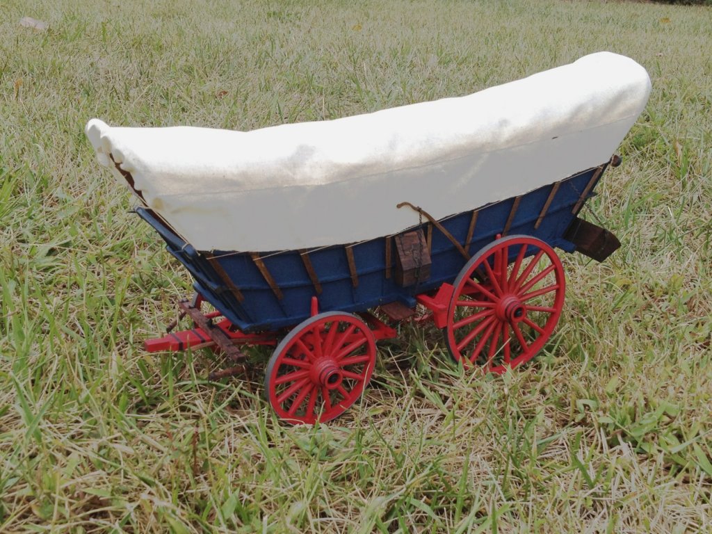
Dan, when you first purchased your Stage Coach I followed suit. I even spent time on the Scale Horse Drawn Vehicle web site (which makes me enjoy this forum all the more). I have now built ME's Stage Coach, Conestoga, Doctor's Buggy and Chuck Wagon. The carriage works shown by Mike seems to be the common method of supporting all kinds of wagons. If I were to put a New England whale boat on wheels, that is the arrangement to be used. I posted a few videos on YouTube on building the Conestoga that can be found by searching for "Building the Conestoga Wagon." I append one photo just for fun. I love what you are doing on the Stage Coach. Wayne
- 151 replies
-
- 10
-
-
"I've always hoped someone would design a square ringed ship simulator" http://www.pdavis.nl/ Is graphically crude, but the elements of handling a square rigger are there. It's old by now, but you can get a feel for how the various sails affect the movement and handling of the ship. Wayne
-
Yes, according to http://www.surnamedb.com/Surname/Crothers
-
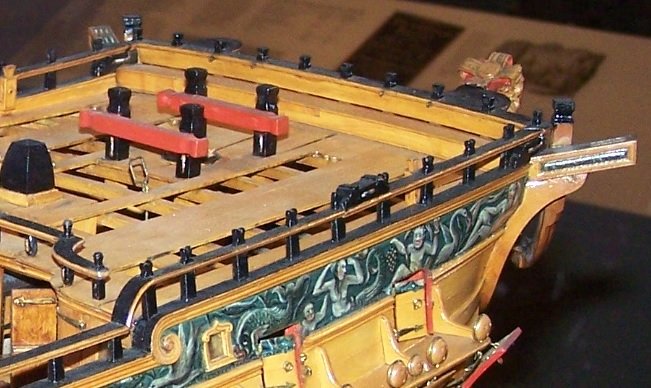
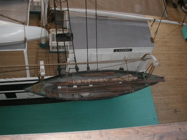
The boats on Lagoda have the oars, paddles, mast, sail, harpoons etc., and line tubs. This photo is not terribly clear, but indicates the contents. In that this model at half scale was built by men who had personal experience with whaling, I would give this arrangement serious weight. Wayne
-
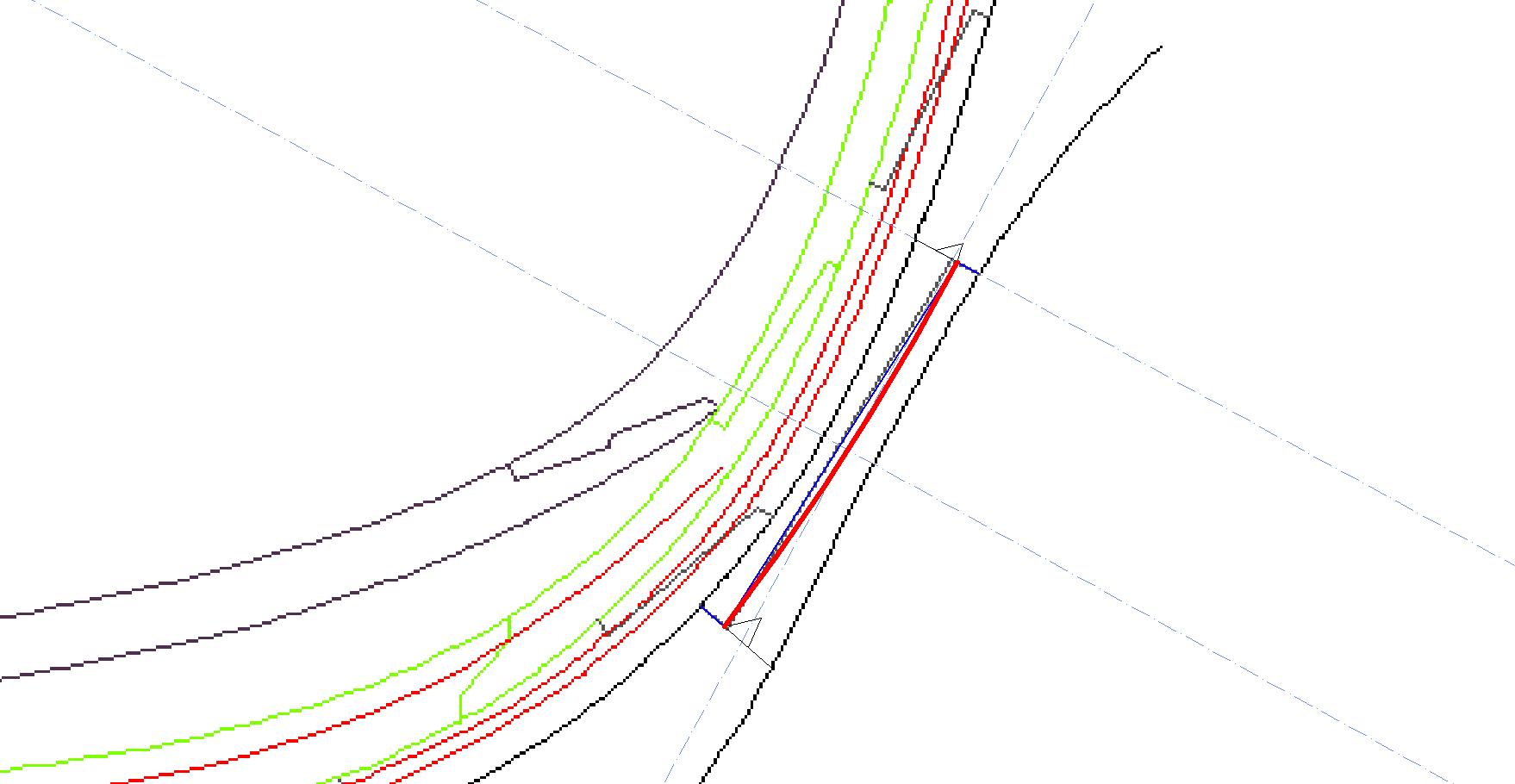
The long line between the lips of the scarph is actually an arc, I suspect. Several years ago there was a discussion of the shape of the "flat" of the scarph of the stem pieces at http://modelshipworld.com/index.php/topic/4080-scantling-questions/page-17#entry289479 If that discussion is accurate, and I suspect it is, then perhaps the scarph of the break water is also curved. The "flat" arc passes through a point halfway between the lips and at the mid point for the thickness of the timber. Attached shows this for the scarph in question. I think this makes a much more serviceable joint. Wayne

-
A quick search found http://www.maritima-et-mechanika.org/maritime/sciencemuseum/sciencemuseum.html scroll down and click for http://www.maritima-et-mechanika.org/maritime/sciencemuseum/ScienceMuseumShipping-11.jpg Wayne
- 3,596 replies
-
- 5
-
-
- young america
- clipper
- (and 1 more)
-
Addictive, indeed.
- 18 replies
-
- 3
-
-
- Early Navy
- frigates
- (and 2 more)
-
On the other hand, the only plan I have that shows the keel scarphs shows them equidistant from one another, so we add some hesitation to the above calculations. Wayne
-
Druxey's "hunch" for a long time has been that the taper begins close to where the cant frames begin. The 24' figure comports well with that notion. I got to thinking. What if the length of the taper also defines the length of the keel piece? For example, if we use Steel for a 36 gun frigate, the length of the keel tread is 126' 2"; the keel is sided amidships 1' 4", forward 1' 2" and aft 1' 1". By this the after taper begins 24' and the forward taper 16' from the respective ends. Steel calls for six keel pieces (the Repository calls for five). Now, if the forward keel piece is 16' and the after piece is 24' (for a total of 40'), then the remaining four keel pieces take up 86' 2" and each piece would be 21' 7". Should one use five pieces the inner pieces would be 28' 8" (or 9"). These seem like viable lengths for the keel pieces. The same procedure for a 74 gives the fore and aft pieces at 24' with five inner pieces of 22' 5" (or 6"). Again, this seems viable. Of course, all these would be adjusted to account for the joints. I have made my keel piece lengths as roughly equal, but the above was an amusing exercise if nothing else. Wayne
-
Upon looking at Fincham again, his words are "It [the keel] is parallel in breadth or siding, excepting towards the extremities, where it is reduced from two to three inches; in the proportion of 1/8 inch in a foot on each side." Ignoring the archaic punctuation, this can be read to mean that the taper extends over a length of one foot per 1/8 inch of differential between the midship and end siding of the keel. Thus, a total taper of 3 inches would begin at a length of 24 feet from the end. The formula in Finch (a foot to 1/8 inch) does not describe the angle of the taper but is a rule to establish where the taper begins. So, there is a taper on both sides that begins at a distance of a foot per 1/8 inch of the total differential. So, I guess I would amend Hoss's formula and suggest the taper begins at 24 feet from the end (if we follow Fincham). I can think of one reason to ignore Fincham for earlier vessels, but I'm not sure of it enough to suggest it here. Wayne
-
By Hoss's citation the taper would begin 4 feet distant for every 1 inch differential between the midship siding and the end siding. In your case, 15-12=3 and so 3X4=12. Hence, the taper would be 12 feet from the end, not 6 feet. I think you may have halved the 3 inch differential unnecessarily. Twelve feet still seems too short for my viscera, but if you follow Hoss's formula that's what it is. I have argued elsewhere for a different way to view the taper, but for the present I am no longer as certain as before. It's just that 12 feet is awfully severe to me. Wayne
-
Many, many thanks. Wayne
-
Hoss, can you provide the page where this is found? Wayne EDIT: Found it in An Outline of Ship Building by John Fincham, 1852, p. 72 for the fore foot.
-
Did I miss the taper?
-
Pro would make no difference. Deluxe will do everything you need.
-
I have TC for PC v19 and have been using TC since v8 (actually v4, but it's a long story). The trace tool in TC is not good enough for our kind of work. Under the best of circumstances it leaves one frustrated with its poor quality. I now have a 64 bit version of TC that no longer has a trace tool. When using Trace in earlier 32 bit versions I quickly gave up on its utility. You might want to check out http://forums.turbocad.com/index.php?topic=11696.0 and http://forums.turbocad.com/index.php?topic=12575.0 for insight from the TC forum. For our kind of work importing the image and then manually "tracing" is better anyway. Wayne