James H
-
Posts
6,133 -
Joined
-
Last visited
Content Type
Profiles
Forums
Gallery
Events
Everything posted by James H
-
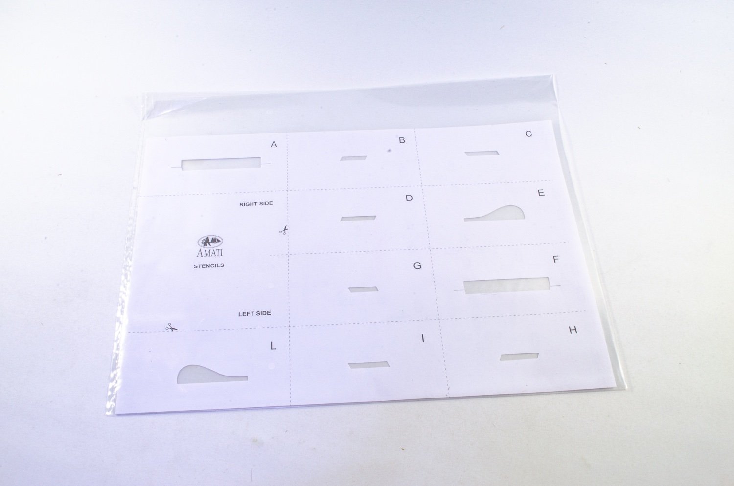
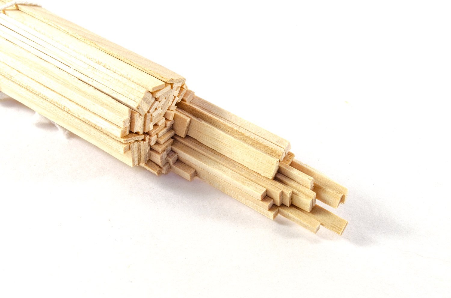
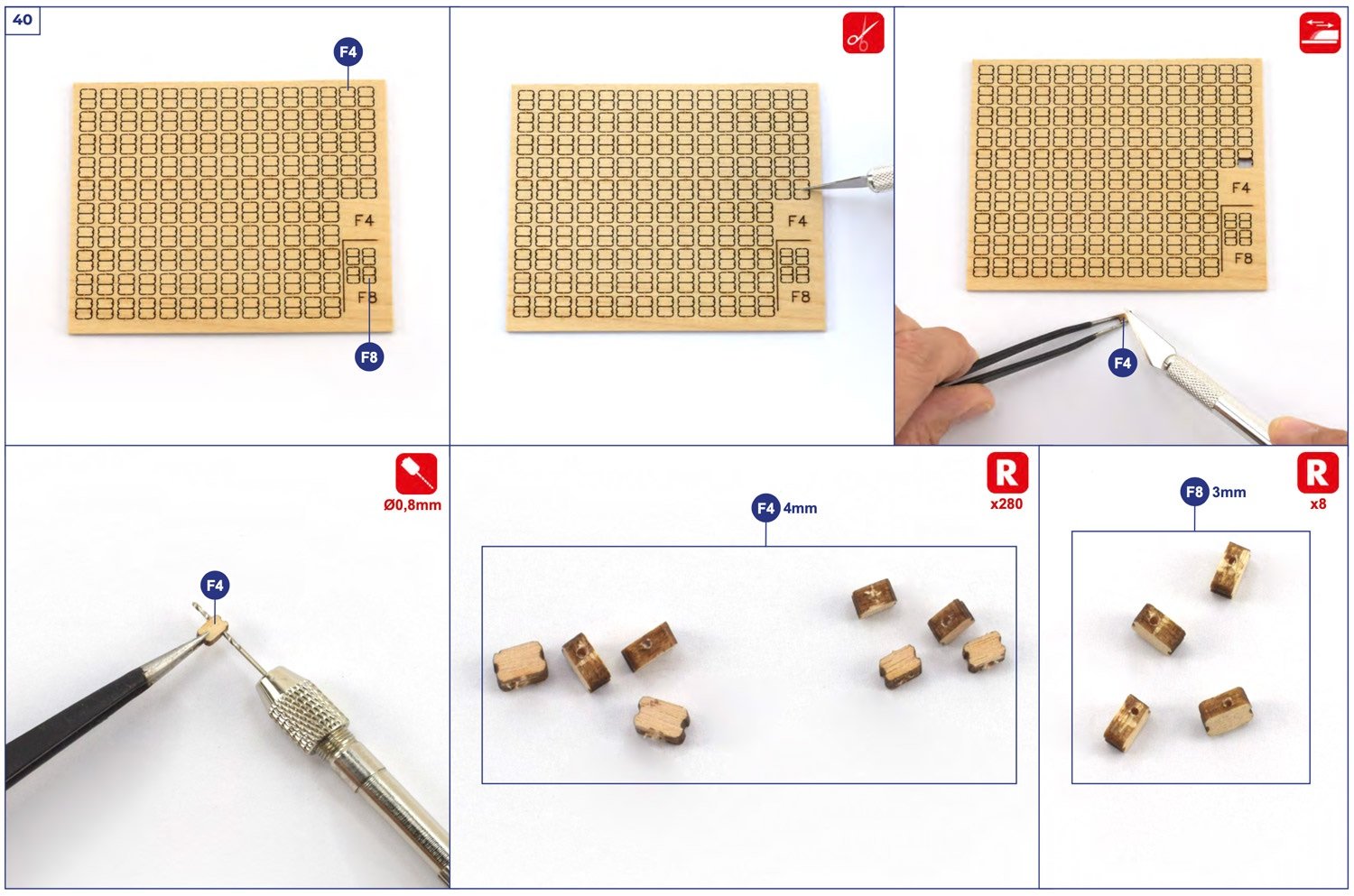
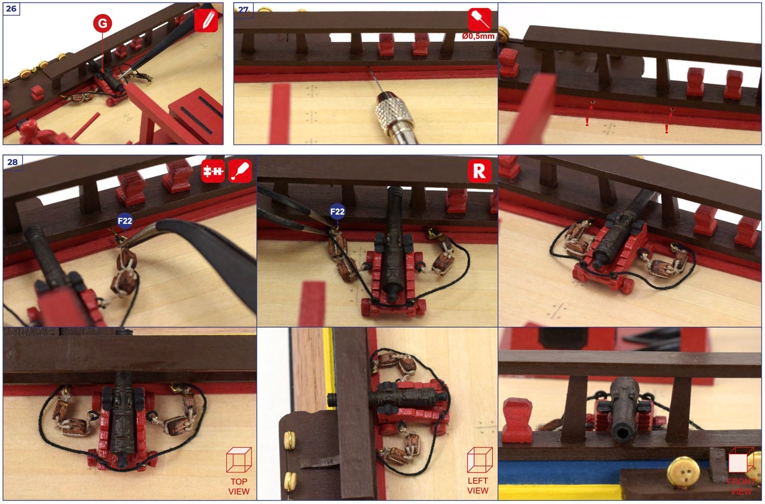
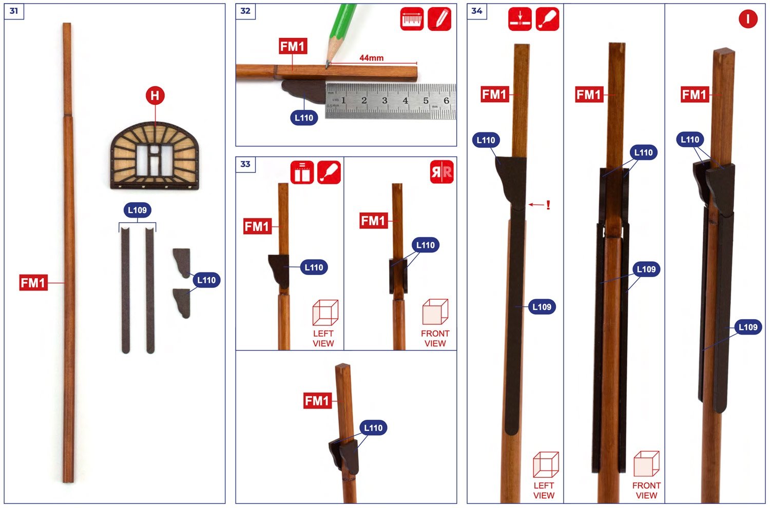
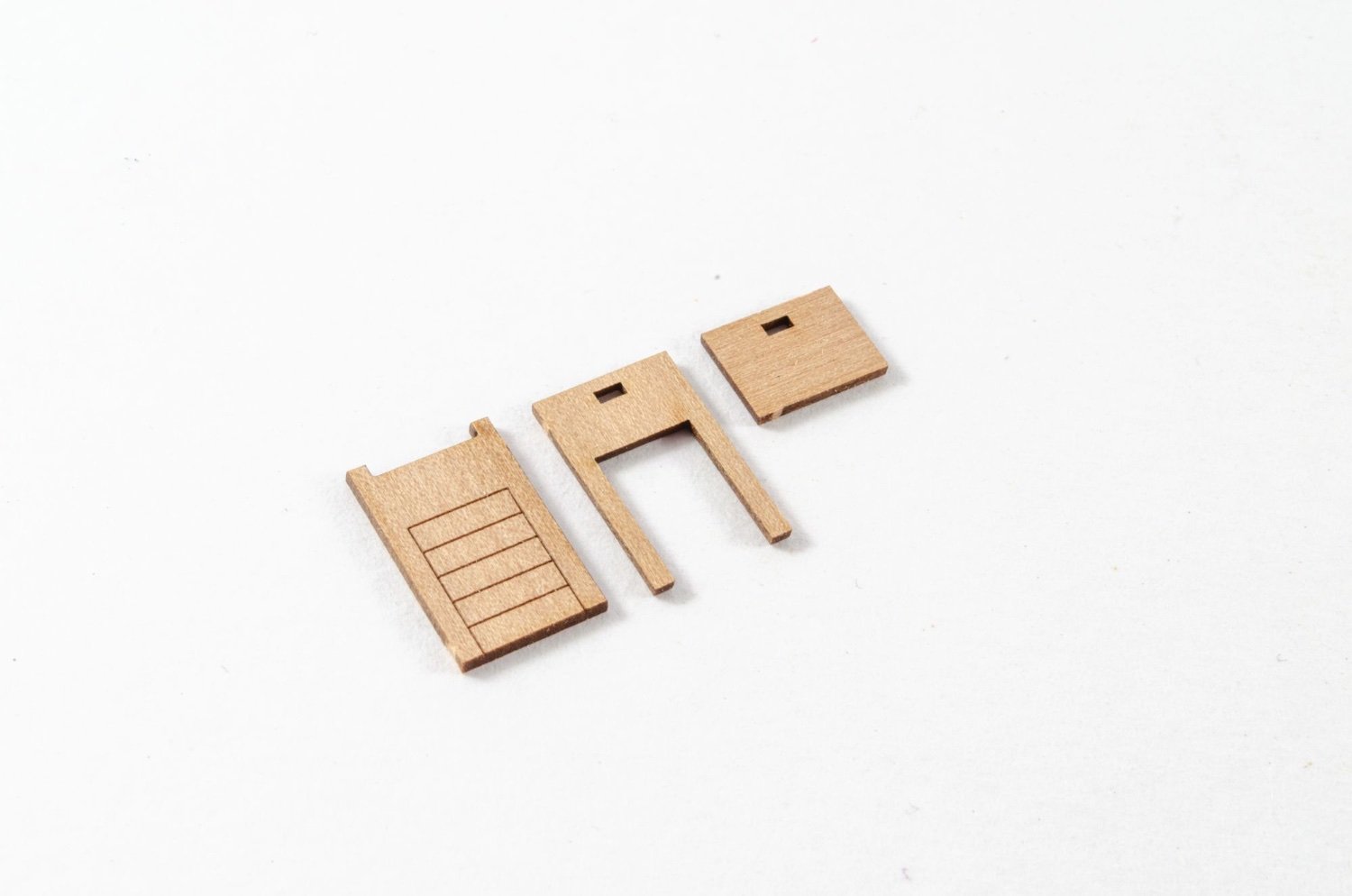
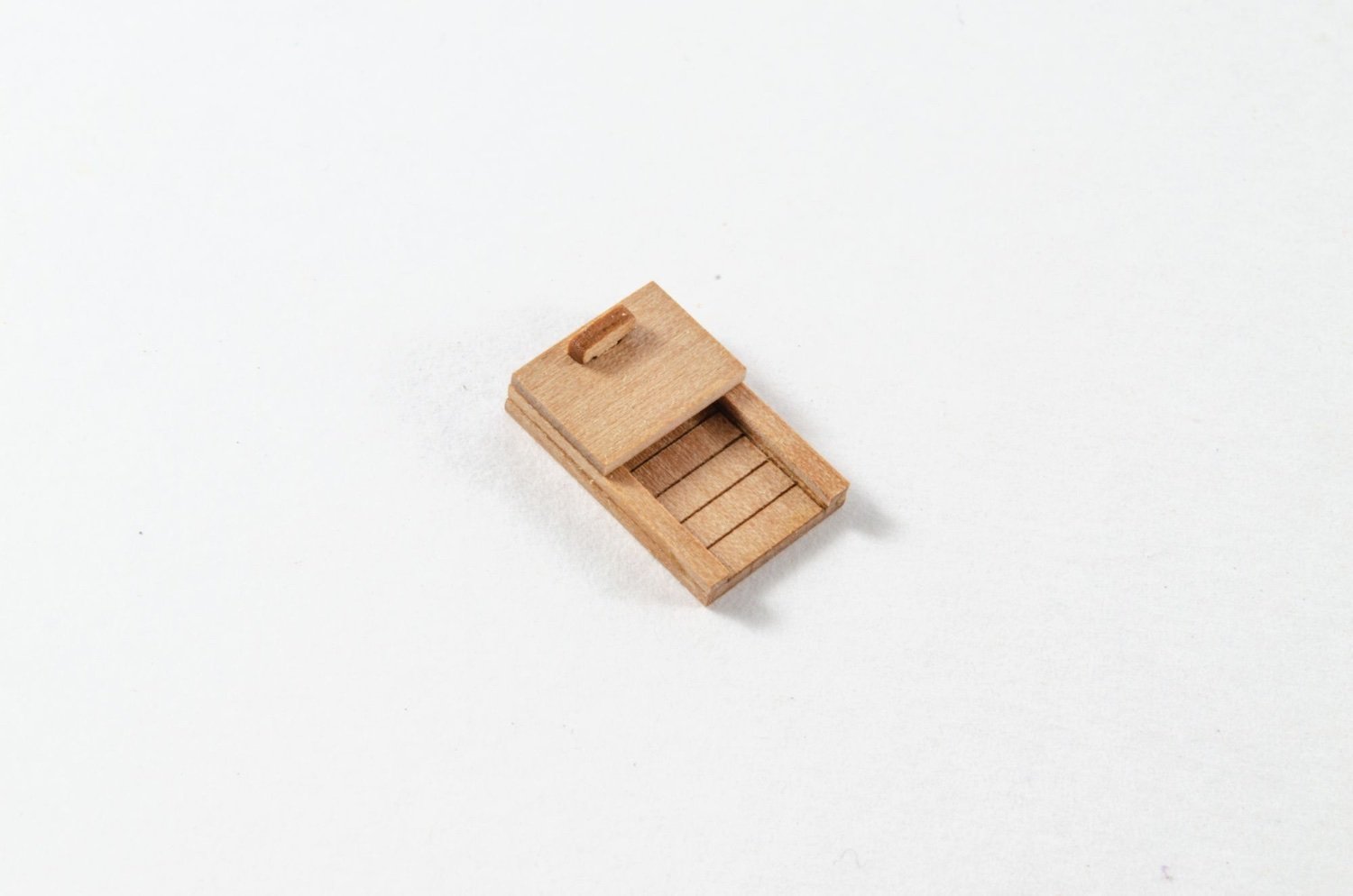
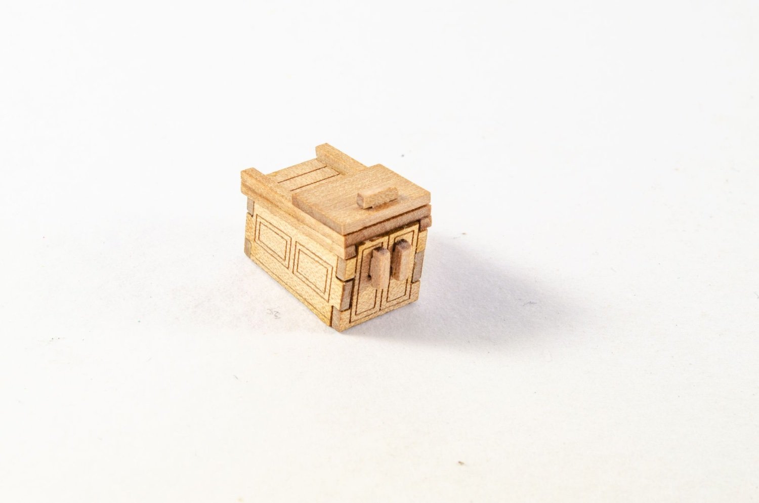
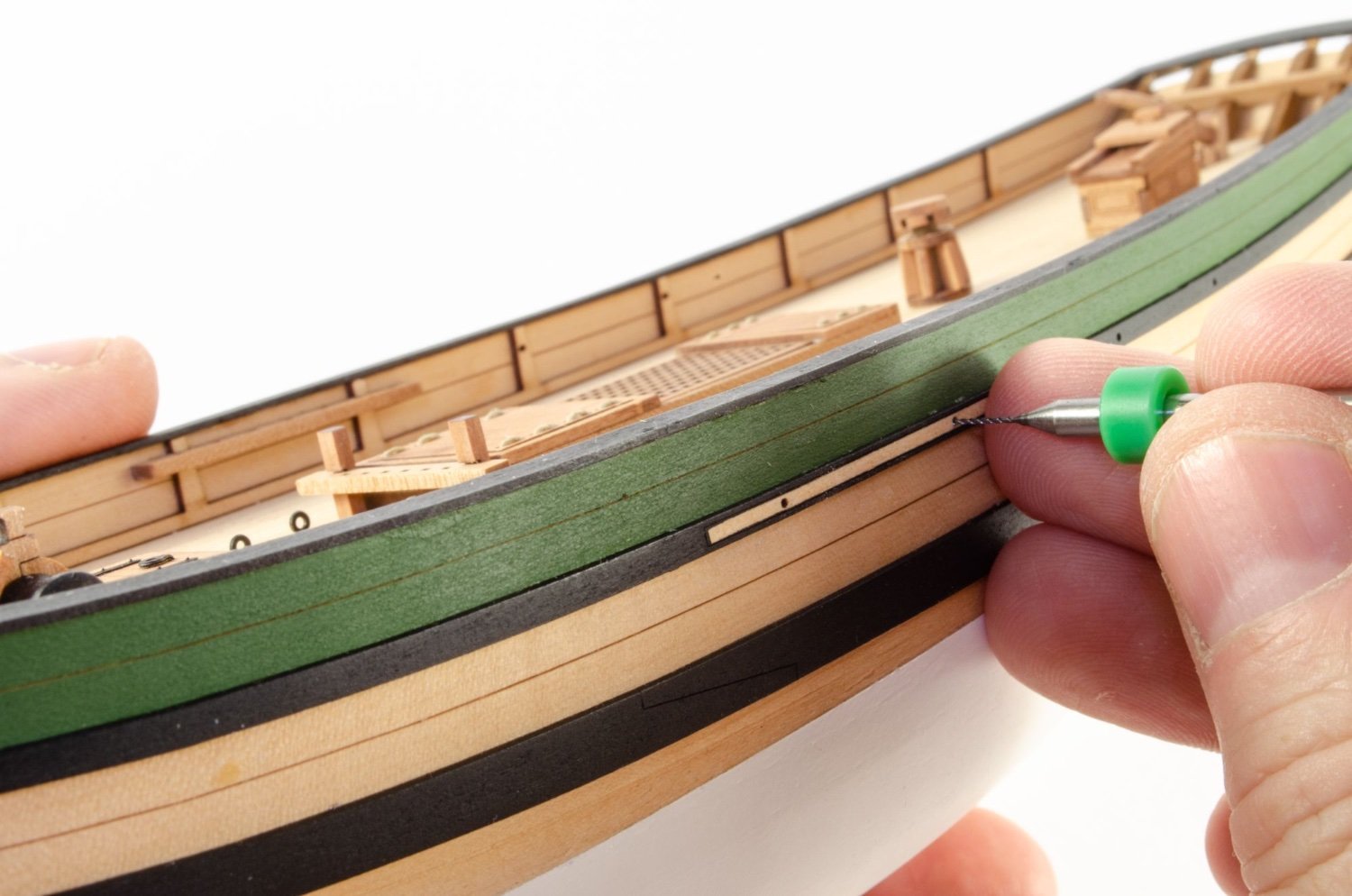
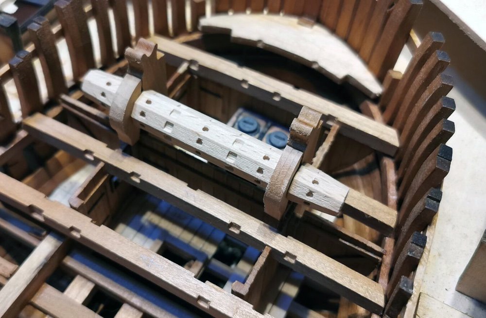
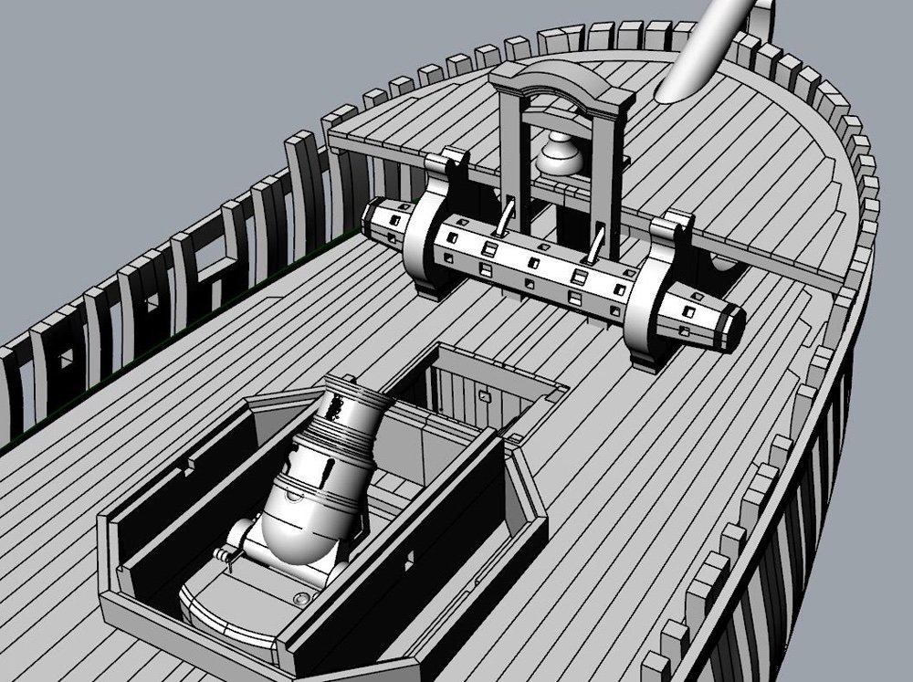
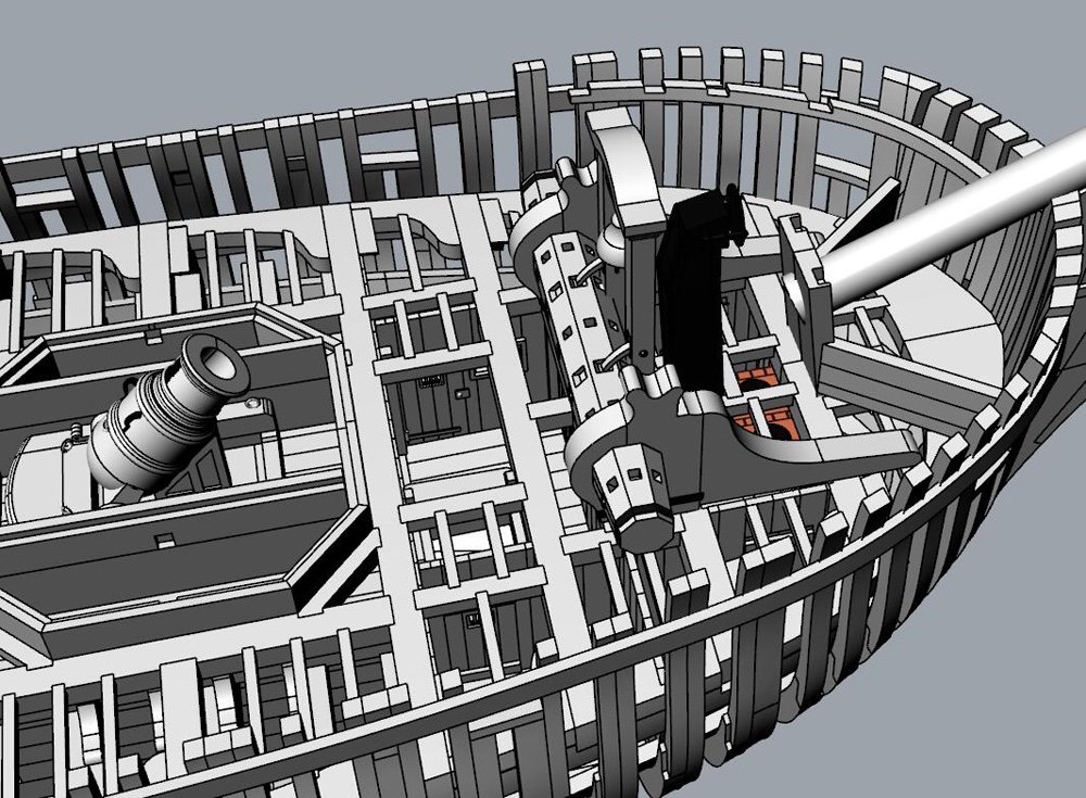
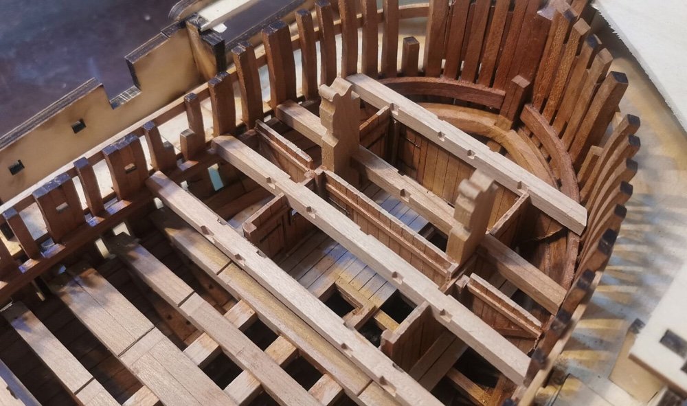
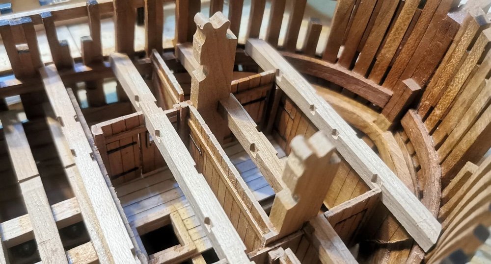
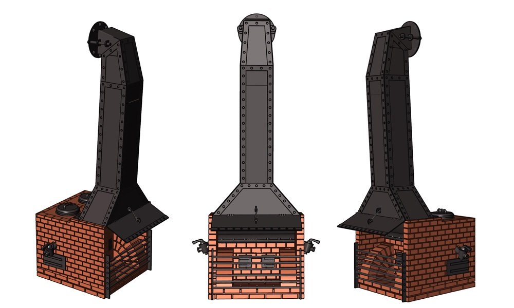
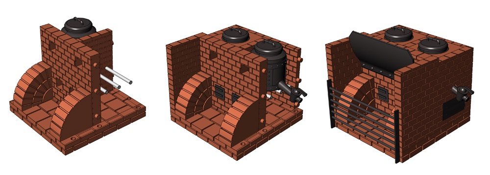
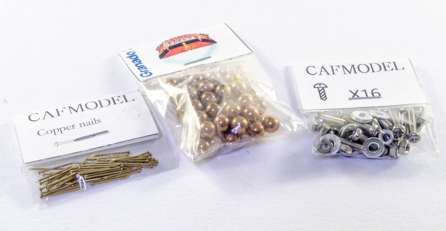
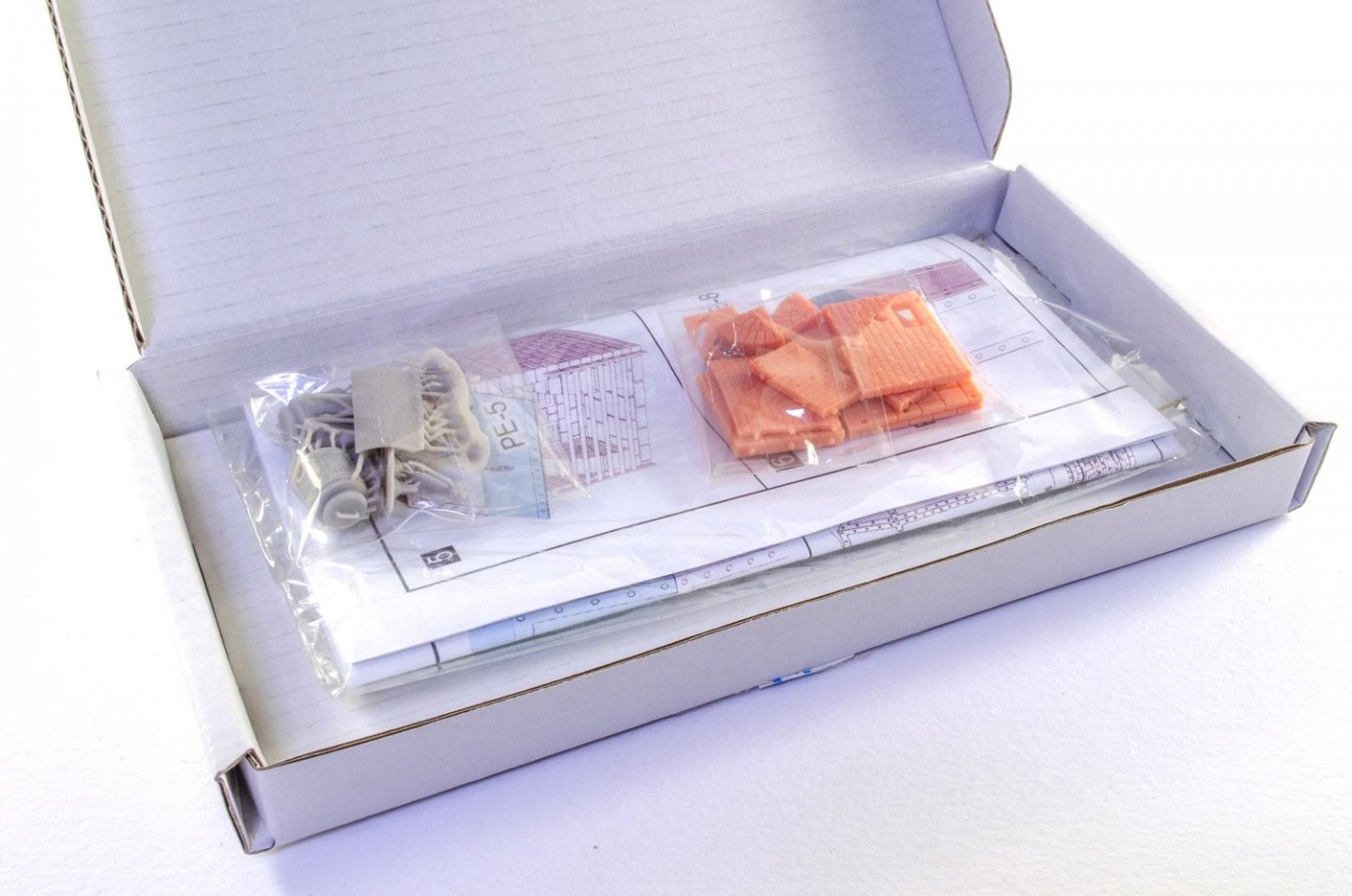
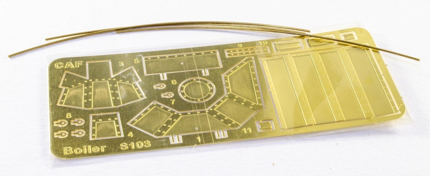
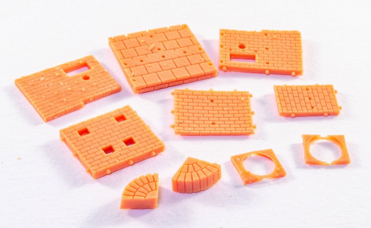
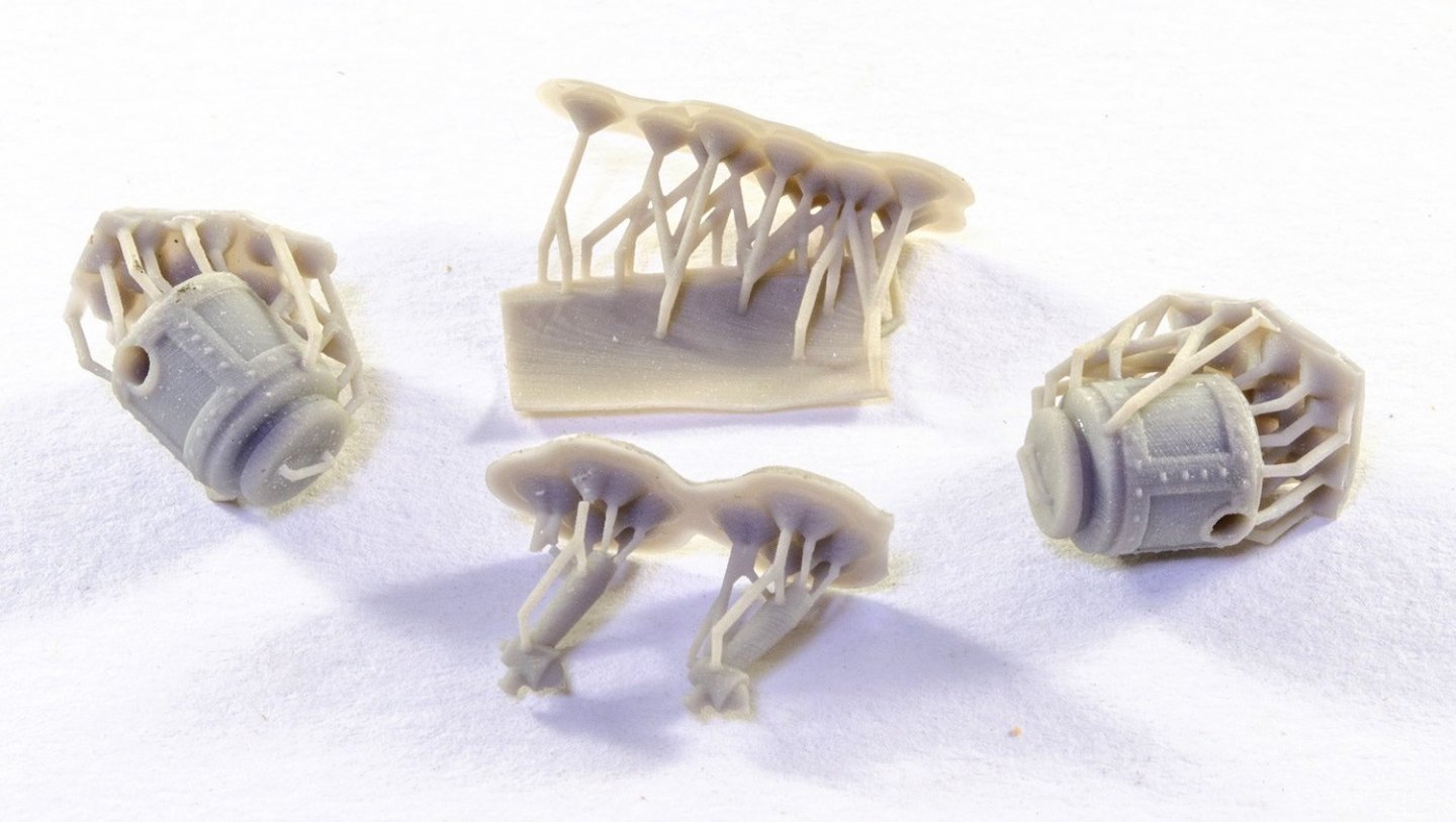
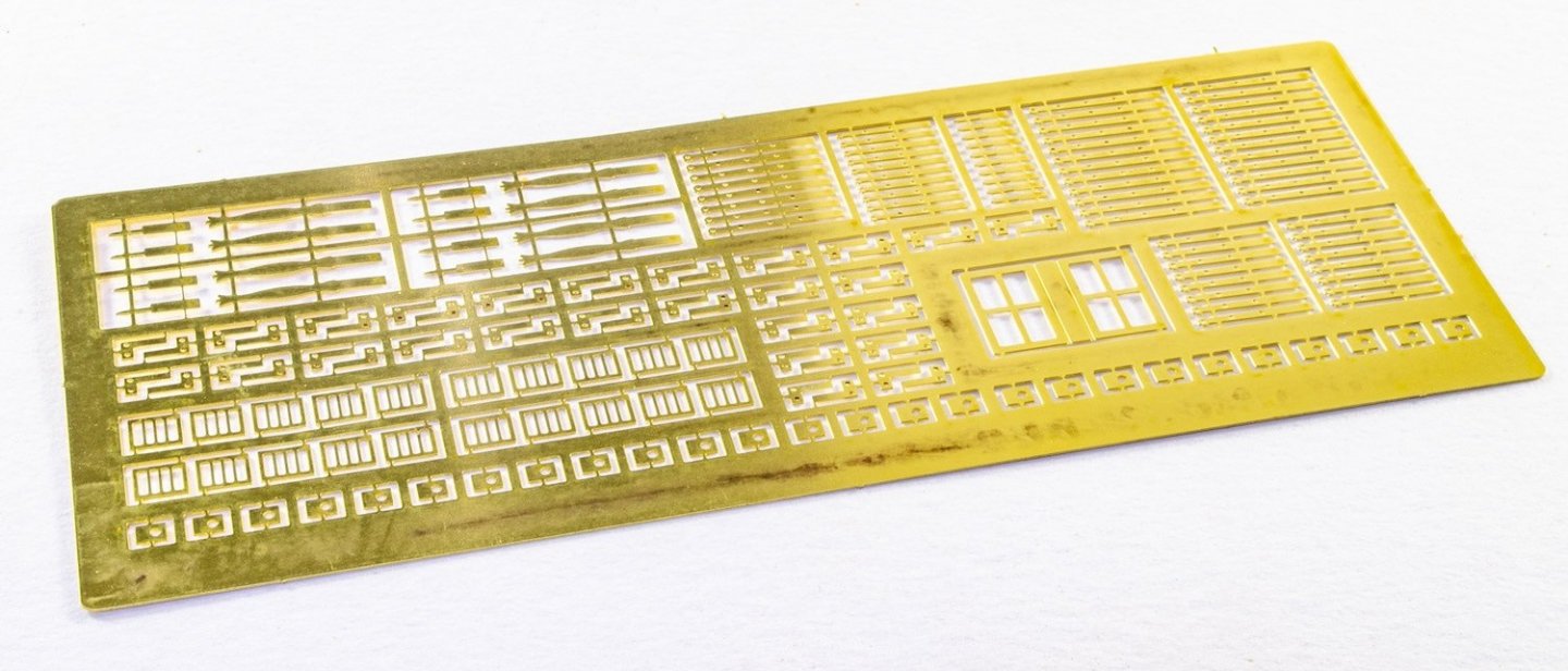
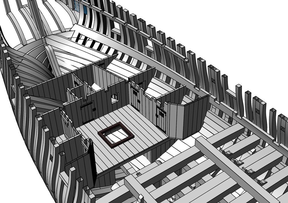
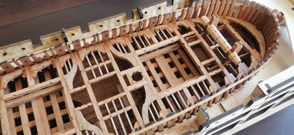
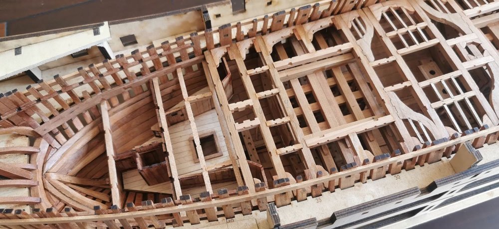
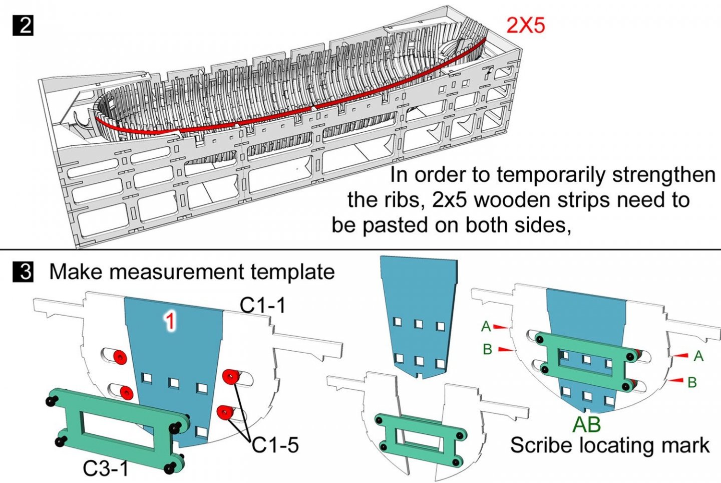
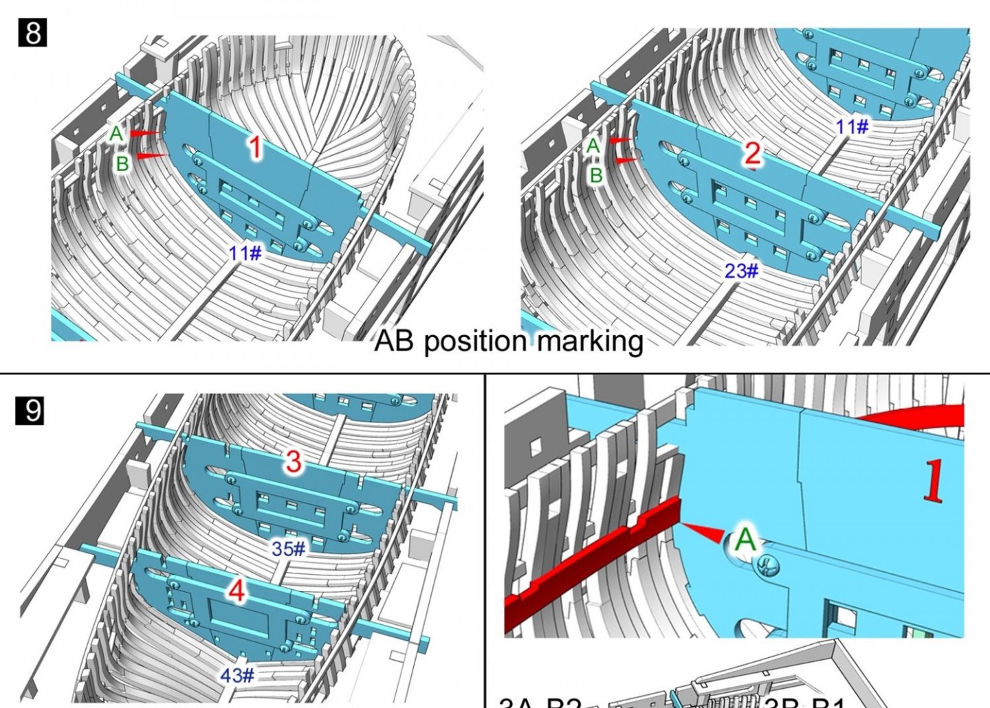
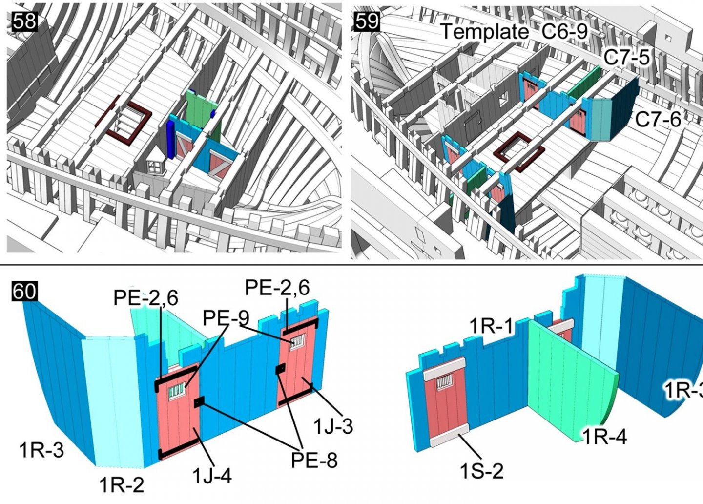
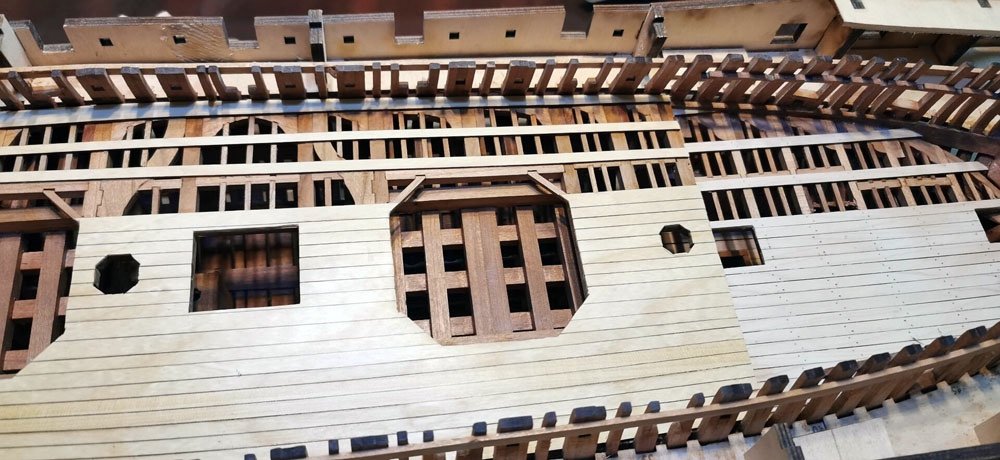
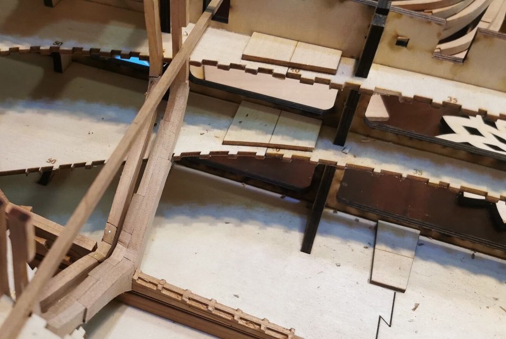
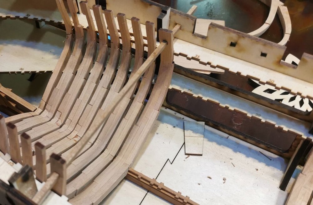
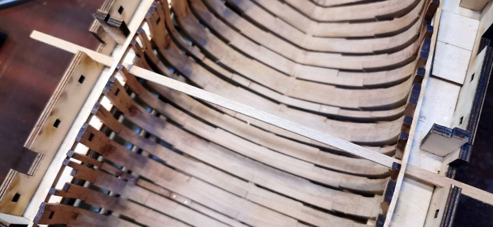
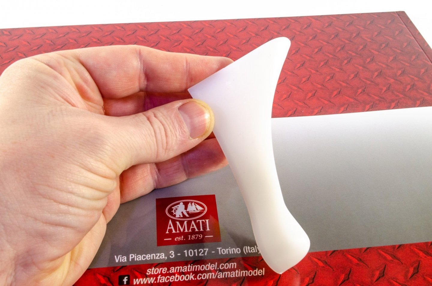
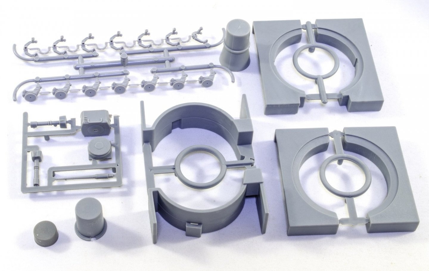
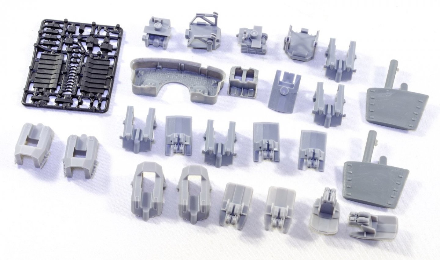
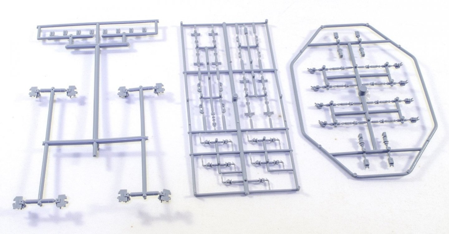
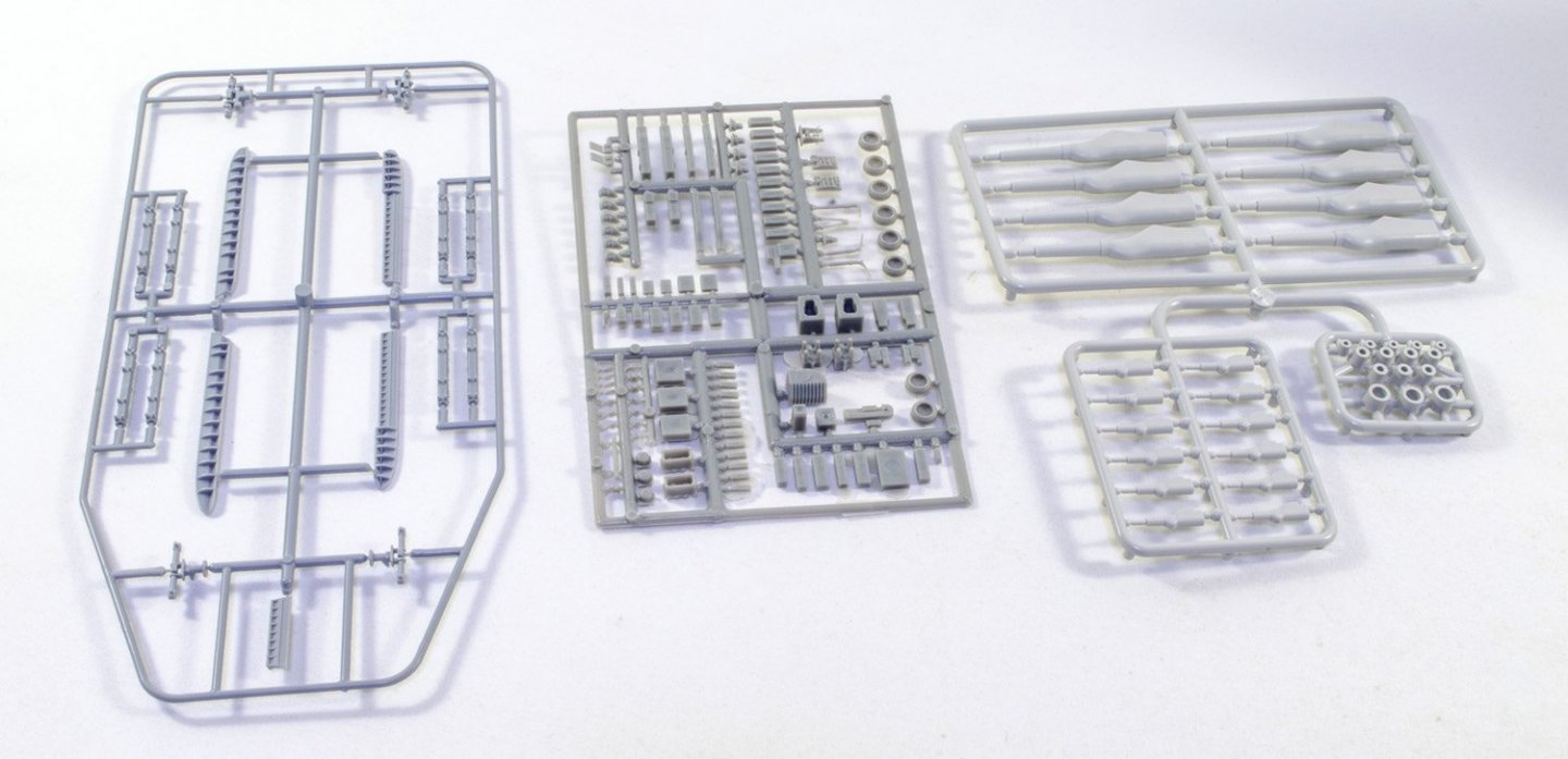
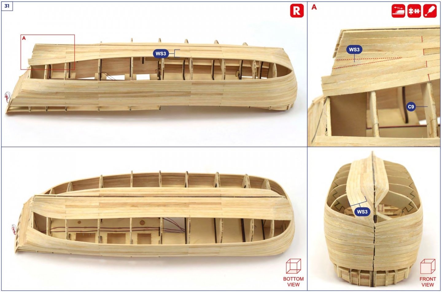
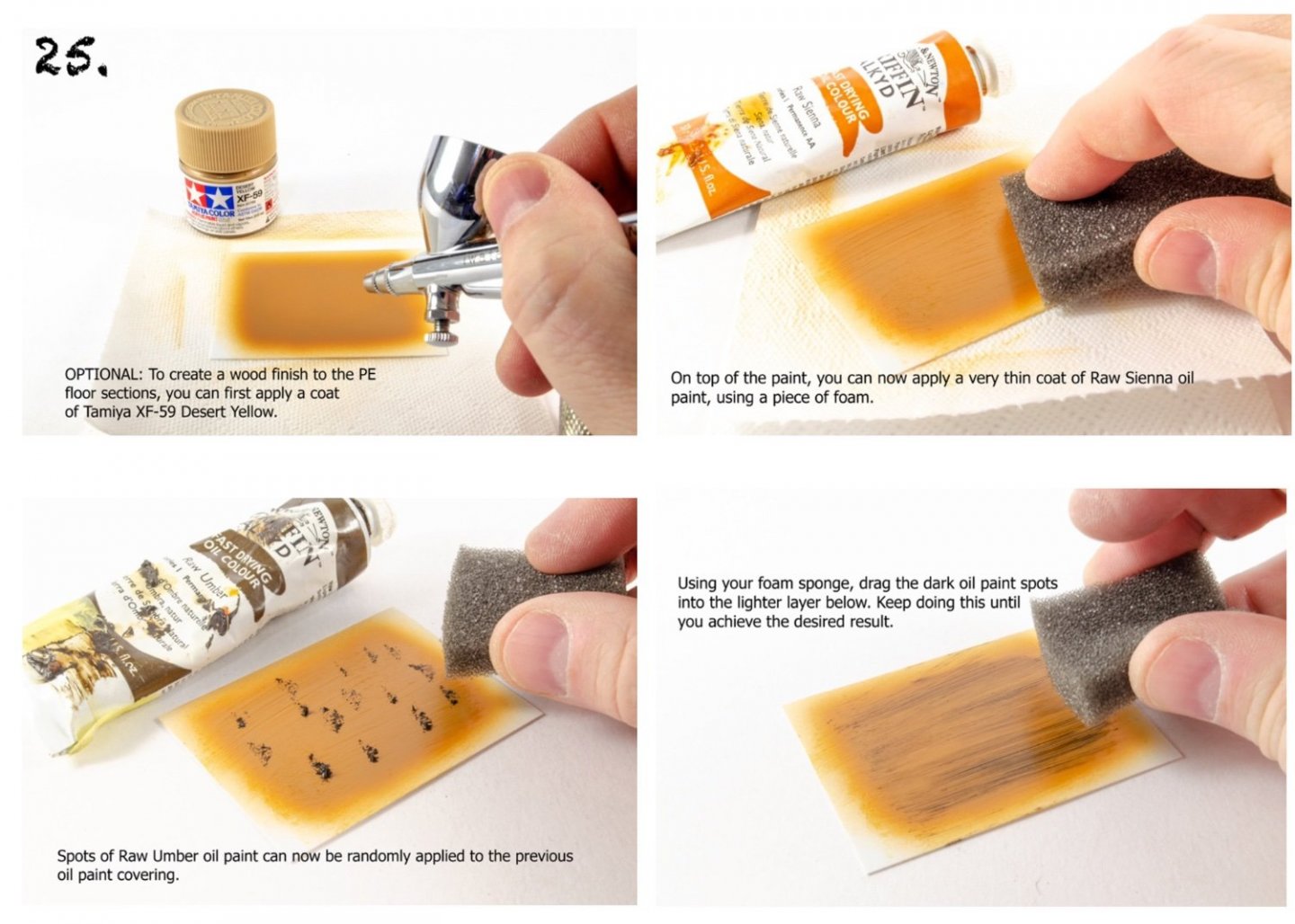
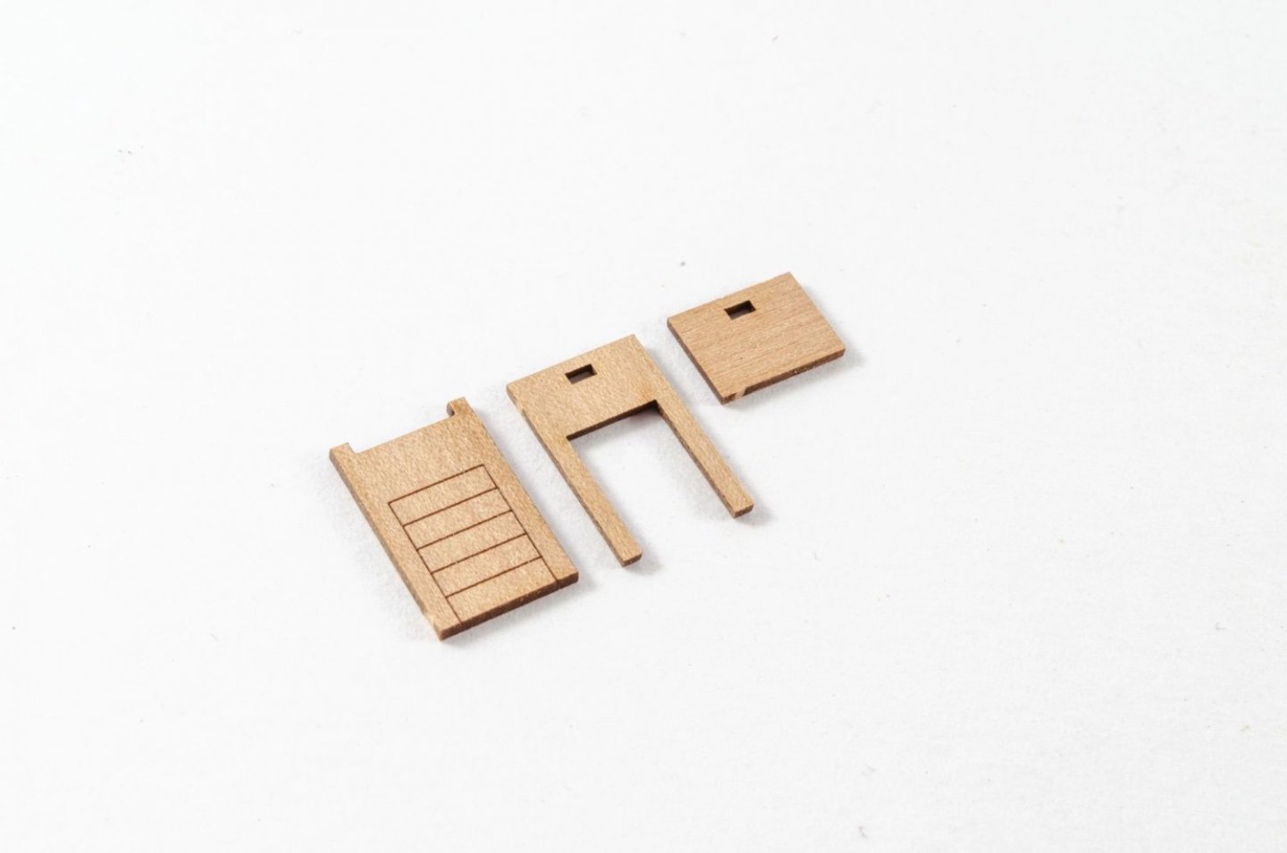
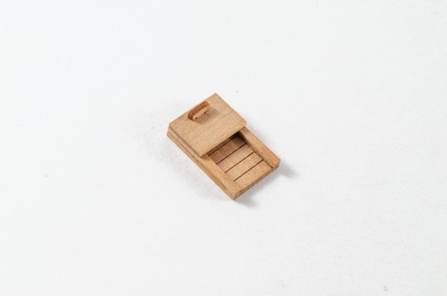
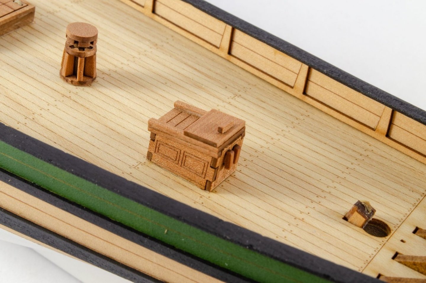
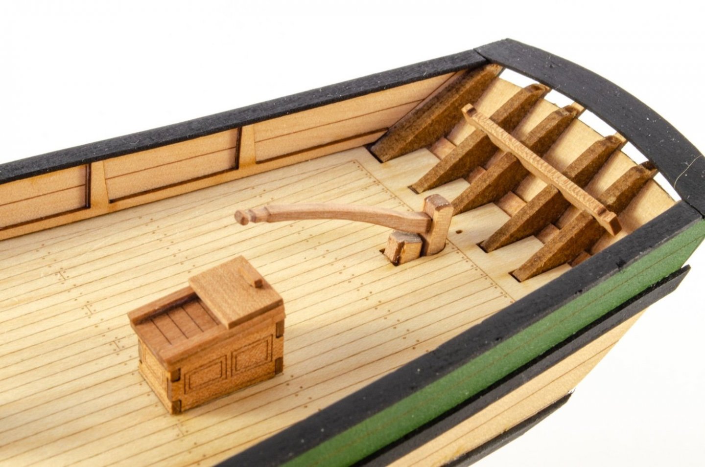
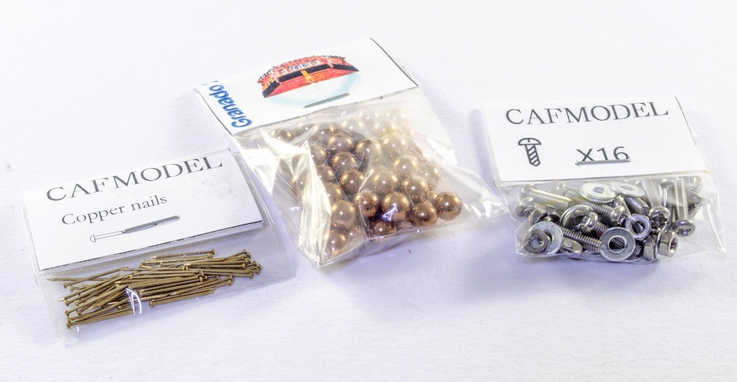
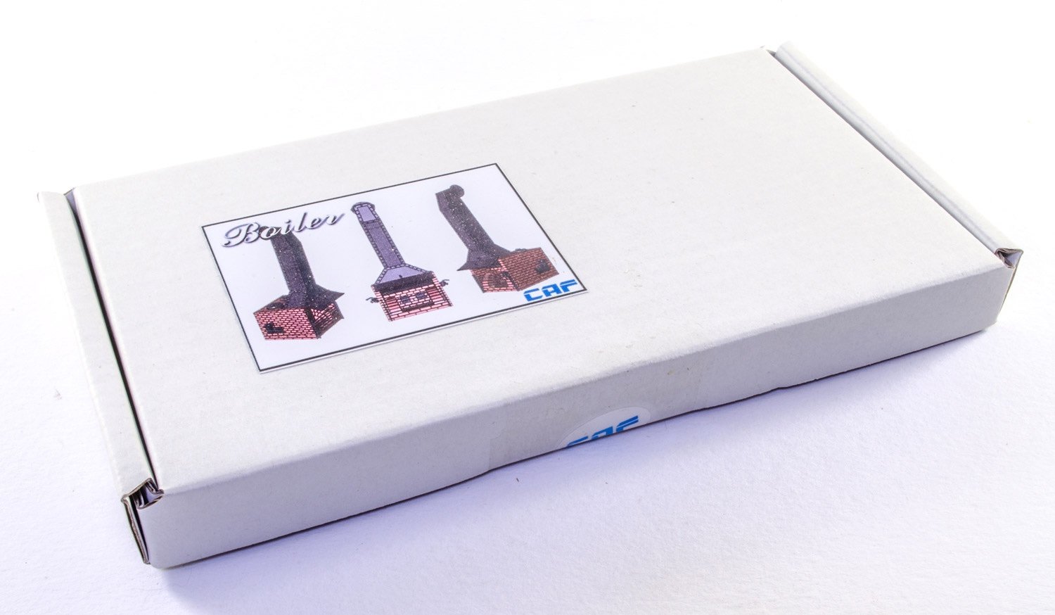
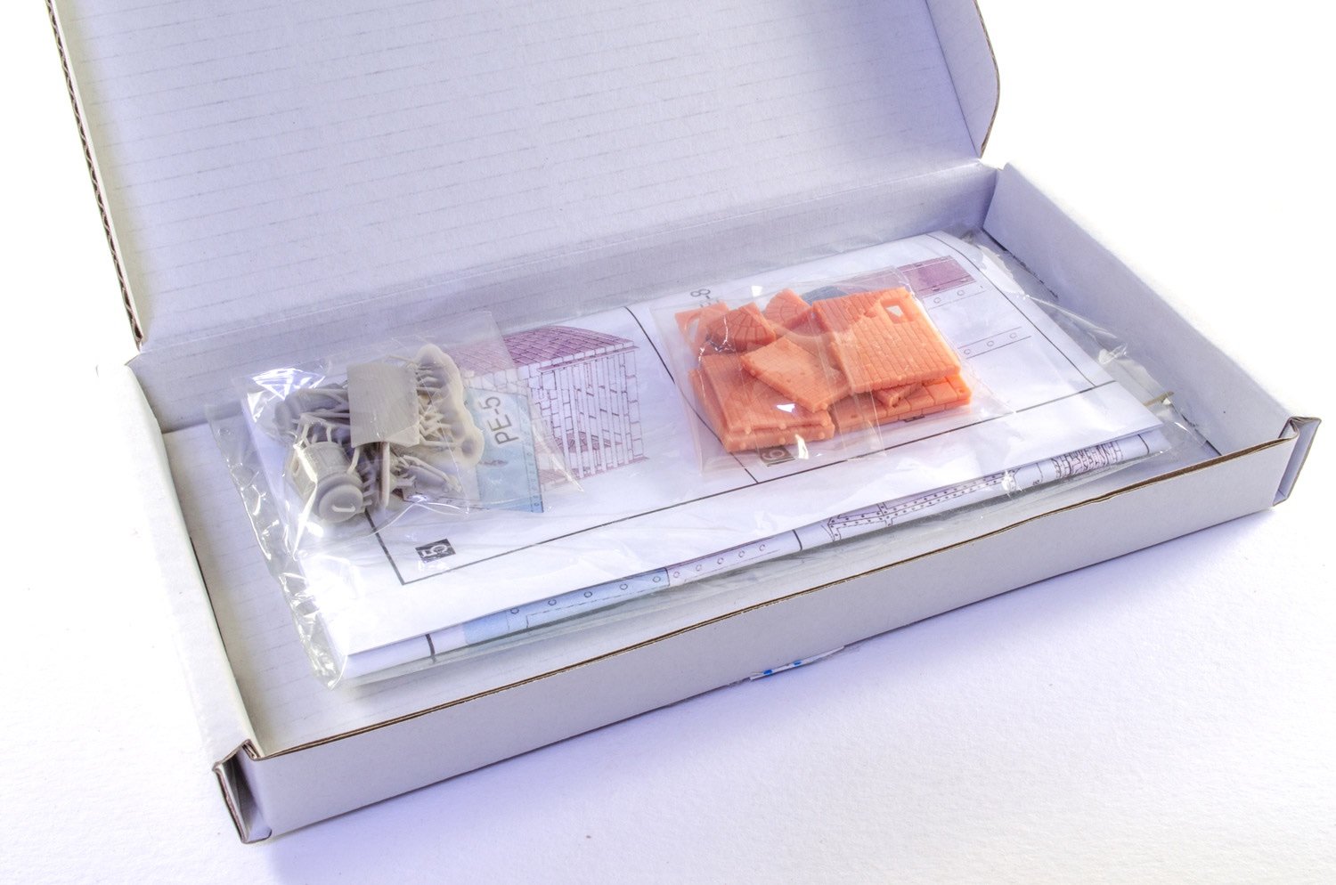
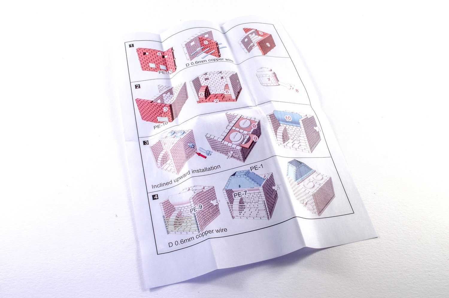
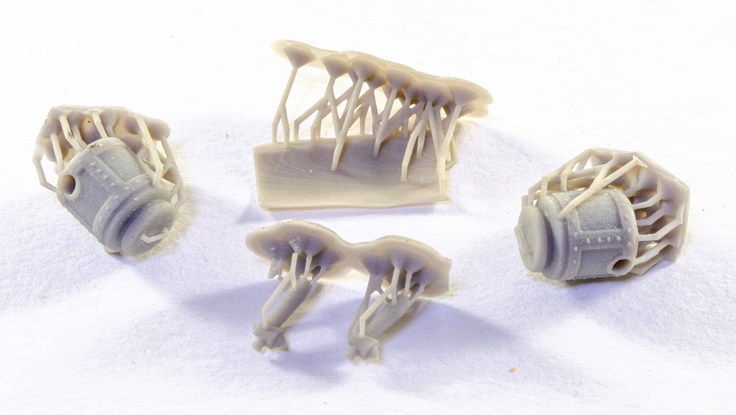
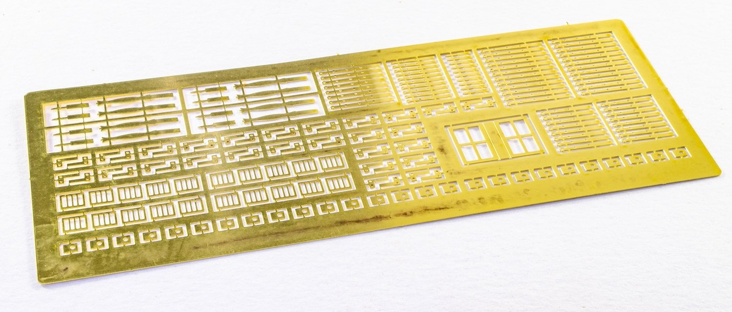
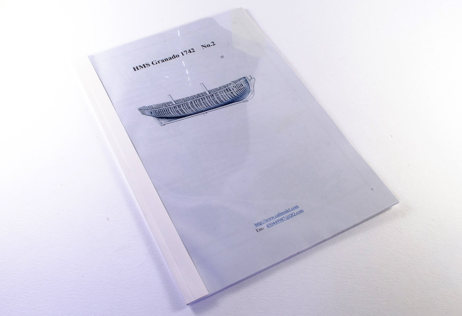
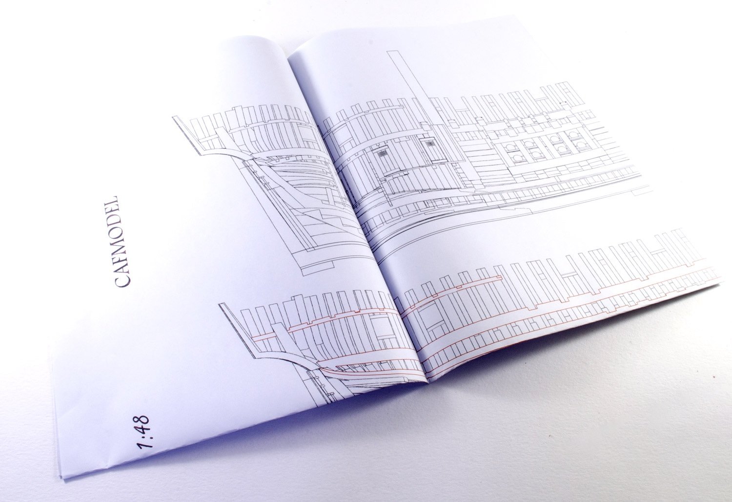
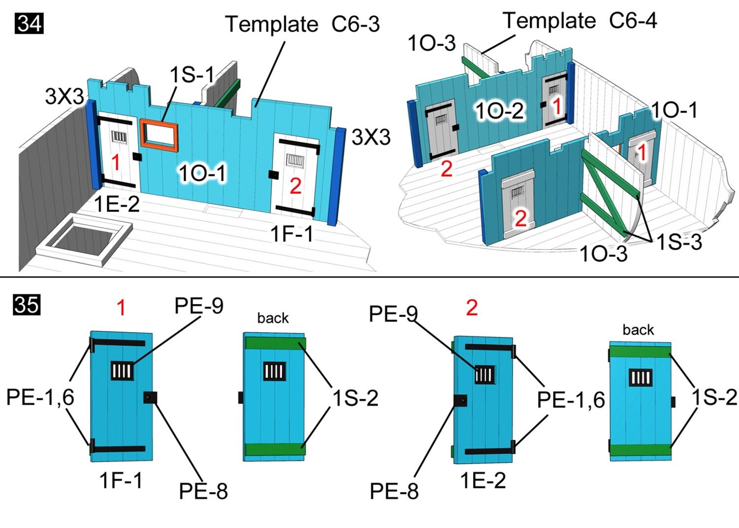
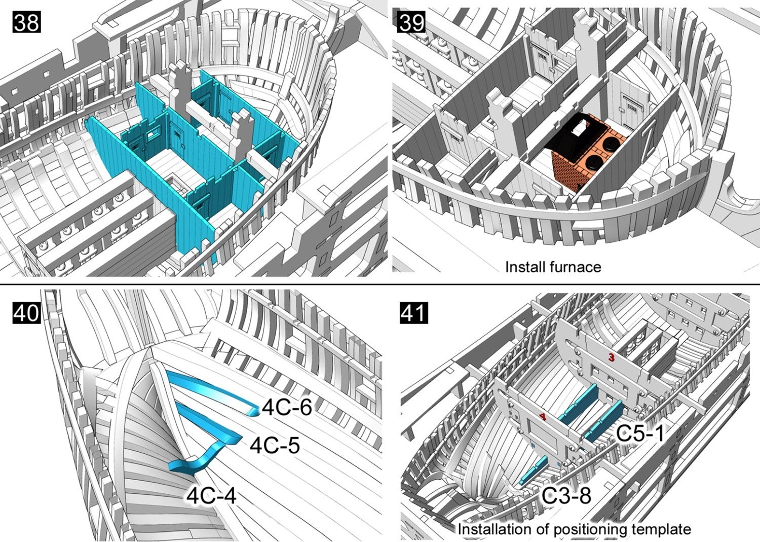
Part 2: Building the hull interior: Available for $327.00 from same link as previously posted: Now you've built the jig, the many frames and decided how you will finally display your model (split or whole), it's time to fit out the interior. Like Chuck's Winchelsea, doing things this was does split up the cost for the modeller, so when you're happy with the work you've thus done, you can then think about getting this package. You're certainly not done with ply yet though. As your hull still languishes in the jig, this pack will give you the parts you need to ensure that it all stays where it should so the internals can be fitted. These are done with a series of adjustable parts which are fastened with screws, and hold those frames securely up against the inside jig slots. I've included some images from the manual so you can understand what I'm actually talking about. The interior of Granado is to be fully appointed with all the cabins, stowage, ammunition store etc....exactly as you would wish to see with an open framed and potentially exploded-display model. More laser cut timber is included, as are a few more parts of CNC-routed parts. A good quantity of strip wood is also included, all nicely selected and sharply cut: Stove CAF have supplied Granado's stove as a 3D print assembly with some photo etch parts to accompany. You will need to remove the supports from the interior hot water tanks and taps, but the brick faces themselves need just some minimal cleanup. Photo Etch Just one sheet is included in this release, but there are plenty of parts to use. Again, the PE is cleanly produced with excellent definition and minimal gates to cut through to release the parts. Remember to use a good etching primer before you apply any paint to brass parts. Trust me, you'll be thankful for that tip! Fittings Just a few fittings here. We have screws for the internal jigs, some brass pins and also the shot for the mortar. Plans and Manual Another A4 manual is included in this release, and this one weighs in at 21 pages, inclusive of the part maps sheets. You will see here how much material is actually included in pre-cut form, such as the internal hull planking, which can be problematic for the average modeller....not that I suggest an average modeller attempts a project like this. This last image shows what you will be left with when this package is complete. And finally, some images which will show you what to expect when the hull starts to be kitted out in the next available package due fairly soon: Conclusion By no means a beginners model, and also not suitable for anyone who classes as intermediate. This really is aimed at those with a lot of nouse and the ability to forward think about 50 steps ahead, plus employ some critical thinking. When build up properly, this model should be an absolute show-stopper, and I reckon there's a good couple of years work involved if you want to get the very best from this kit. At around £500 so far, that actually represents some great value for money on a per hour basis too. Materials quality is excellent and the manuals look easy to understand. Tom is also easily contactable and always willing to help if you should find any problem. Watch out for the next instalment on this as soon as we can bring it to you. Our sincere thanks to Tom at CAF Model for the sample shown in this article. To buy direct, click the link at the top of this article, and remember that you will need to add both packages (A & to your cart if you wish to purchase at same time, so save some postage costs.


-
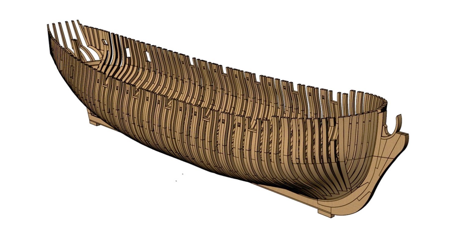
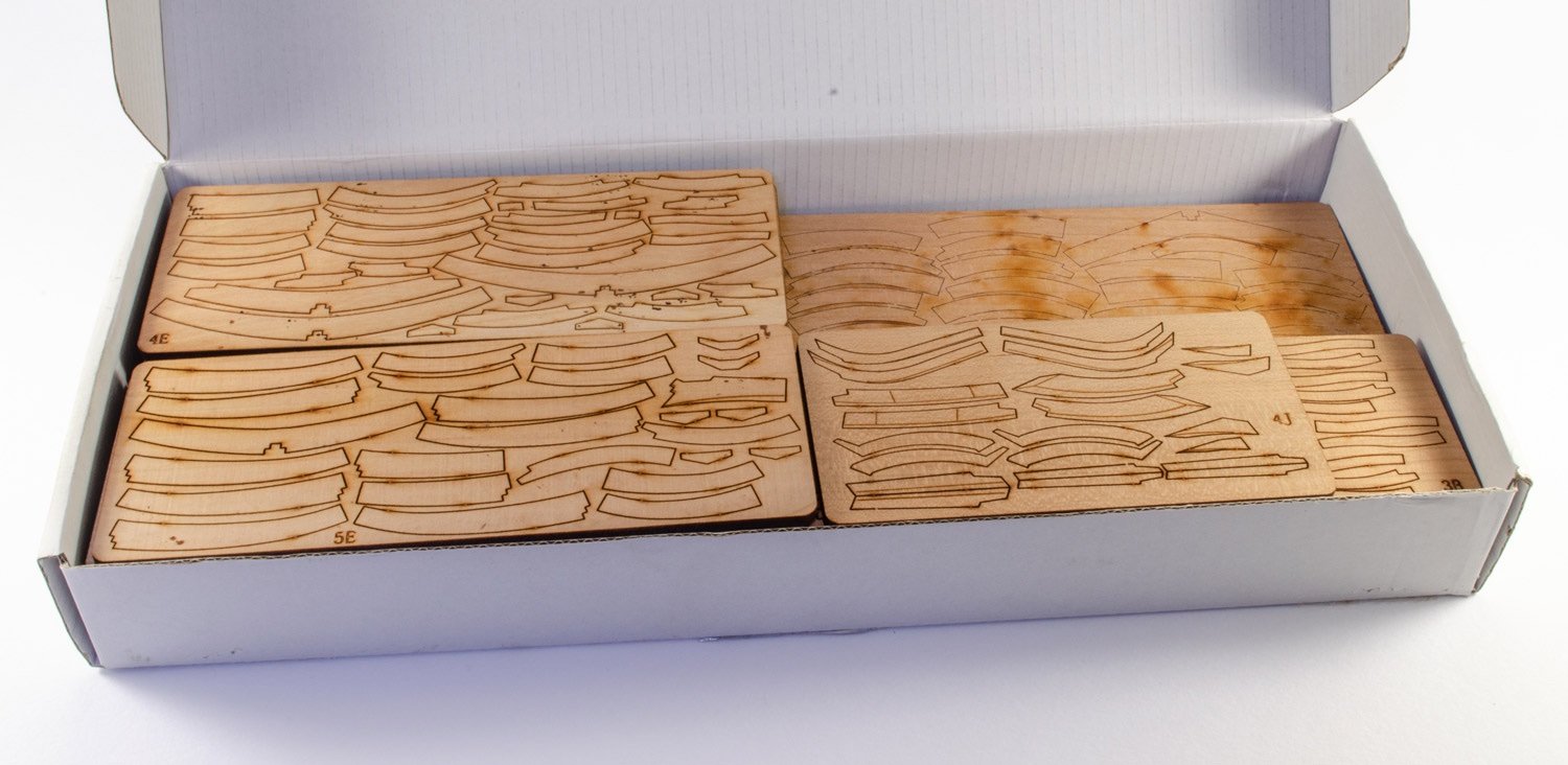
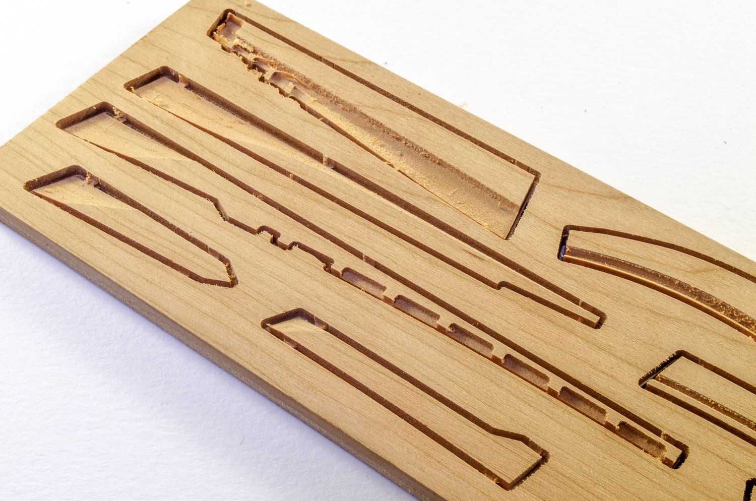
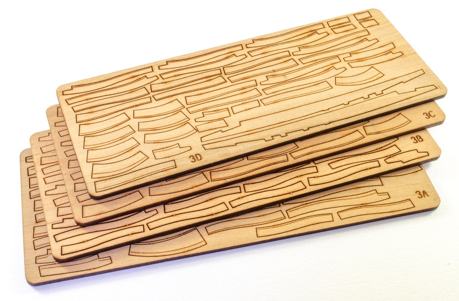
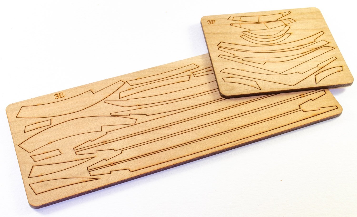
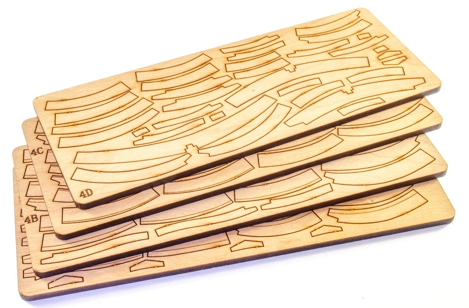
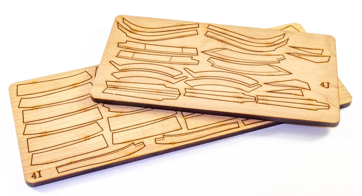
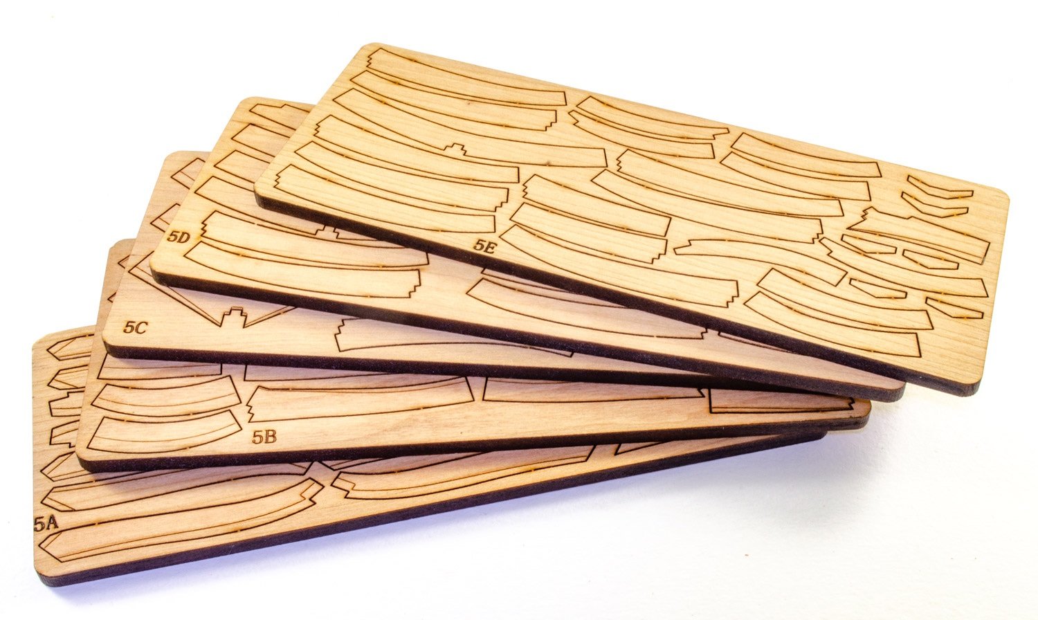
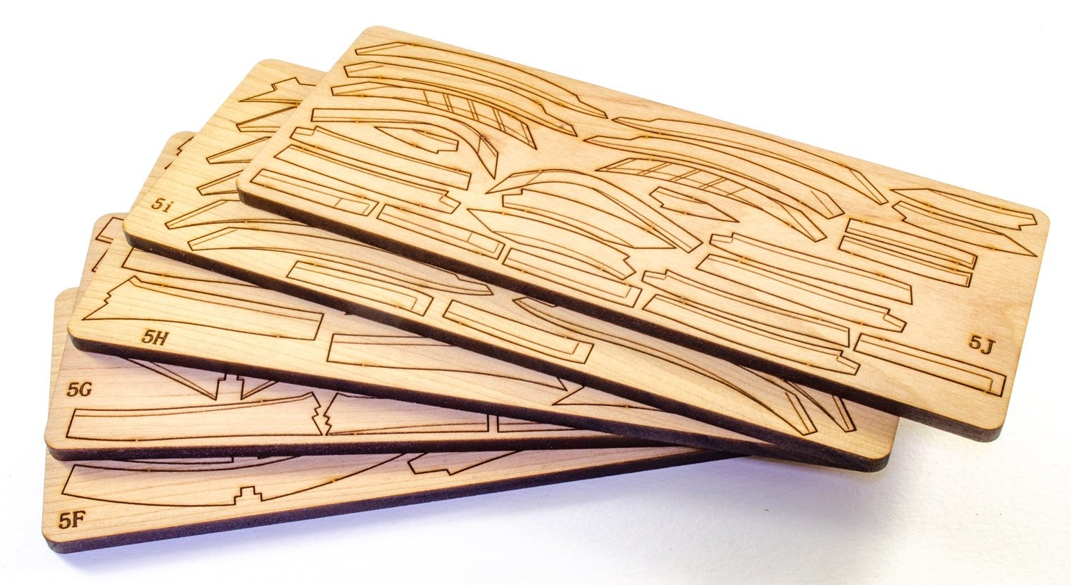
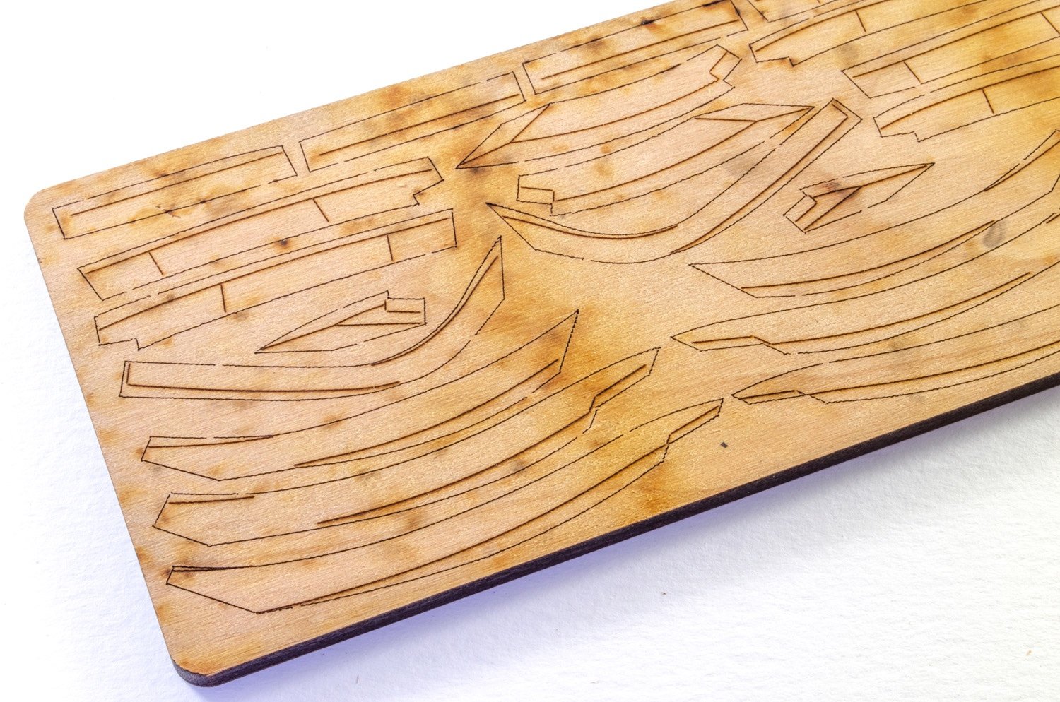
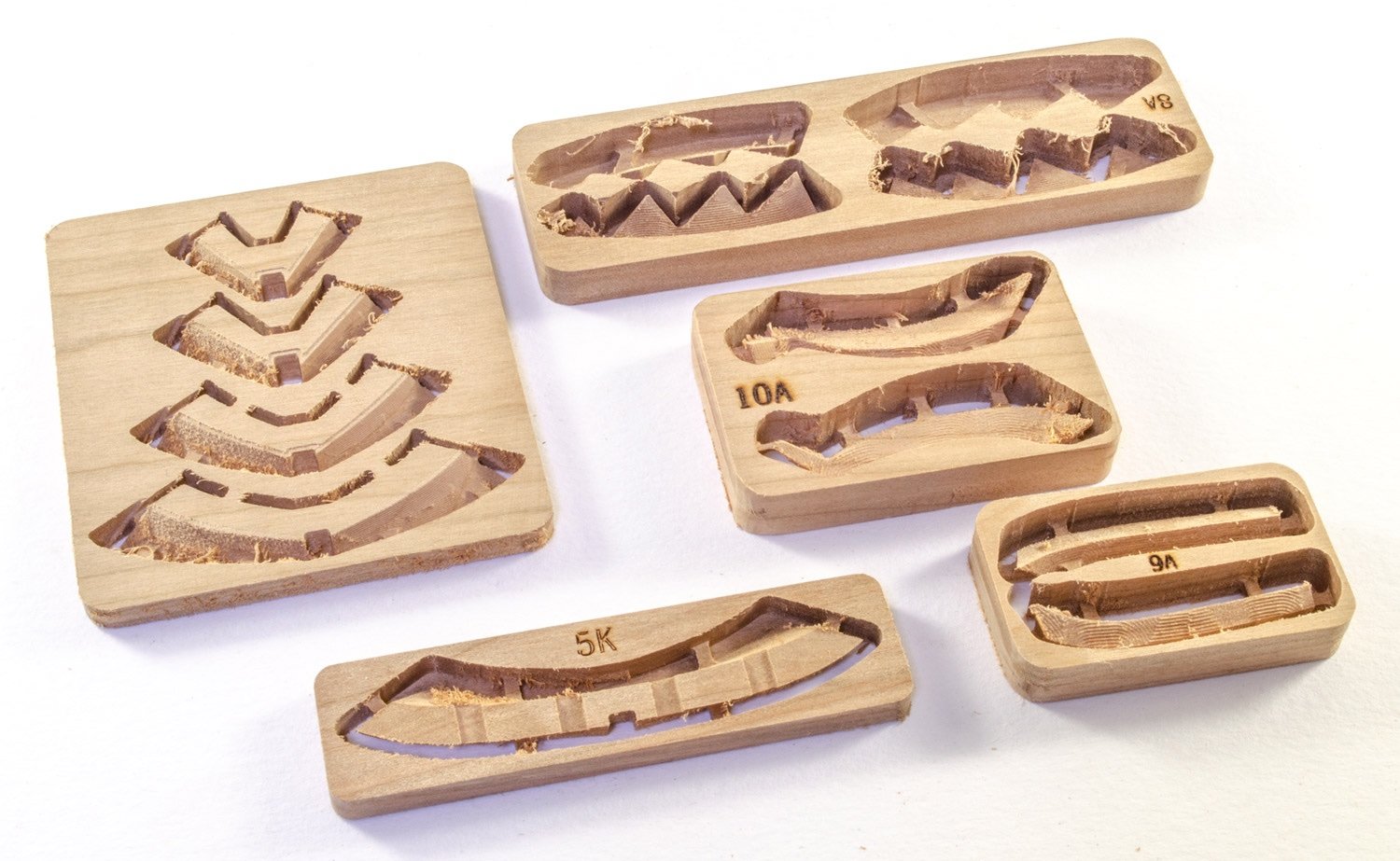
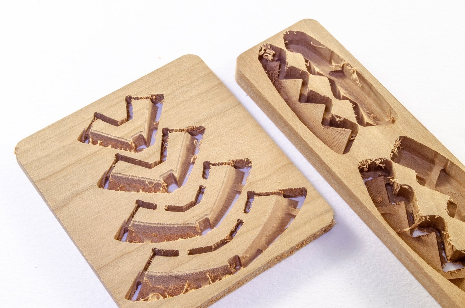
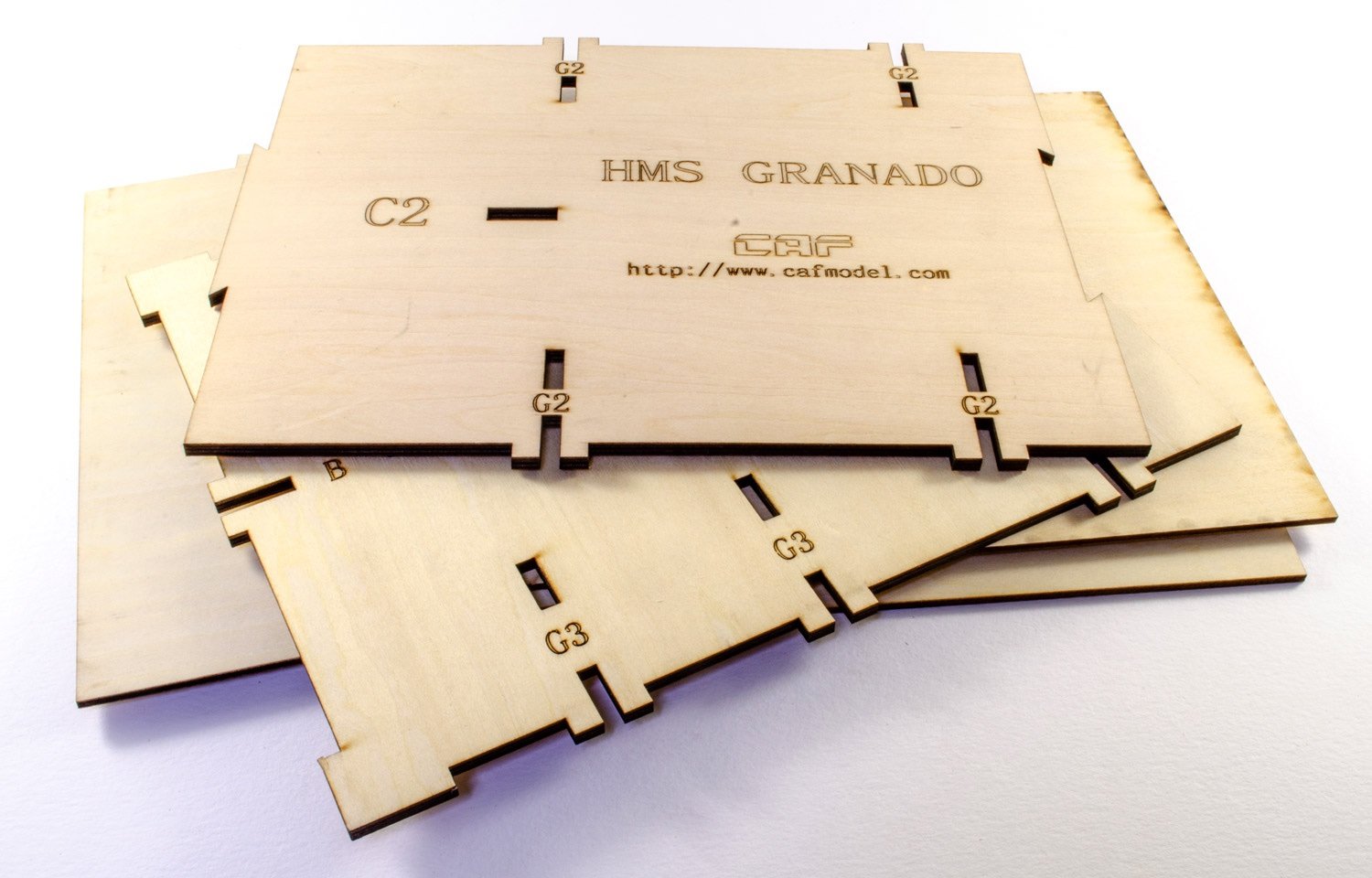
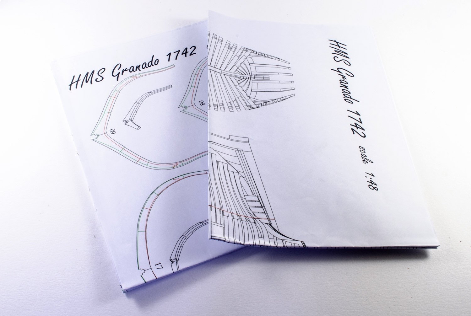
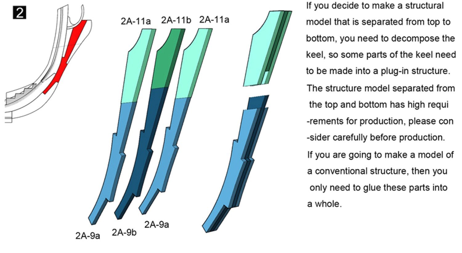
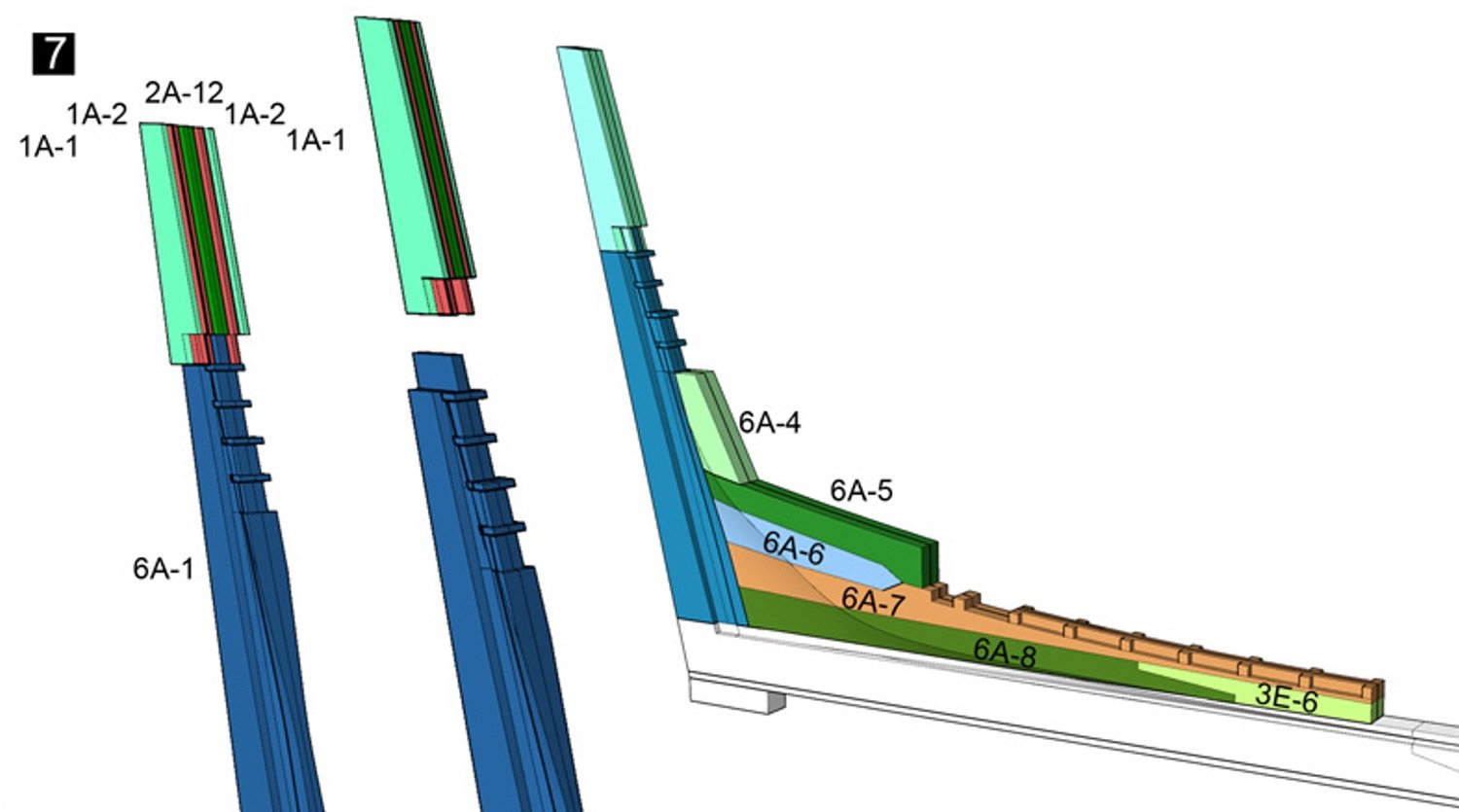
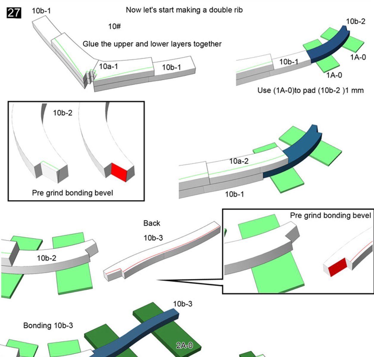
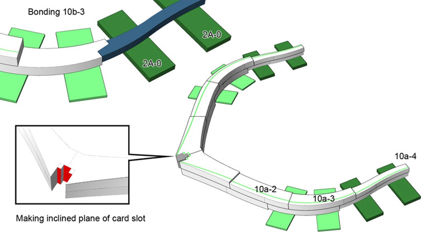
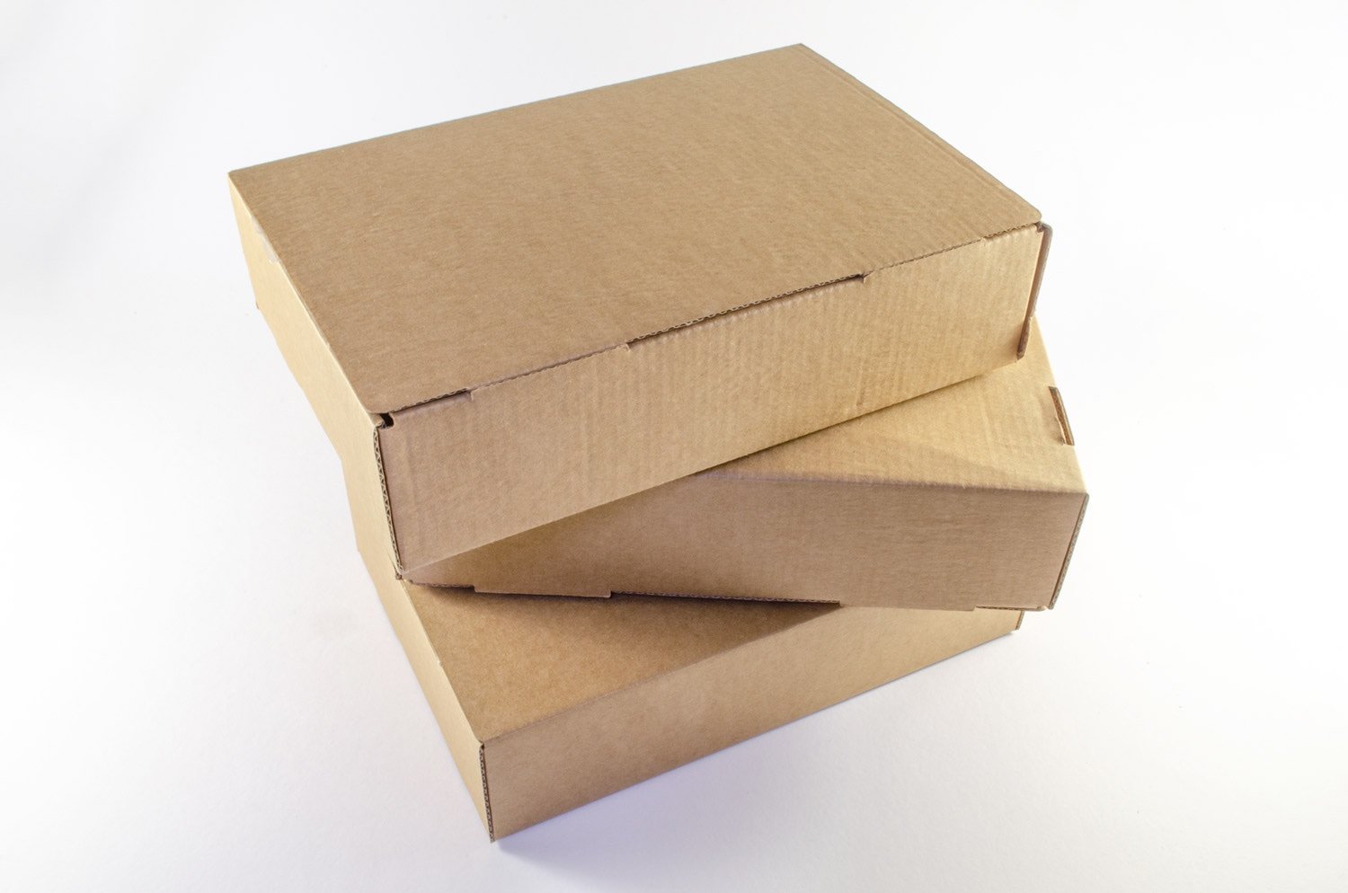
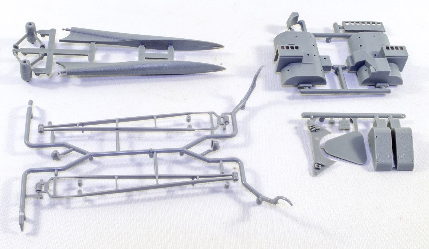
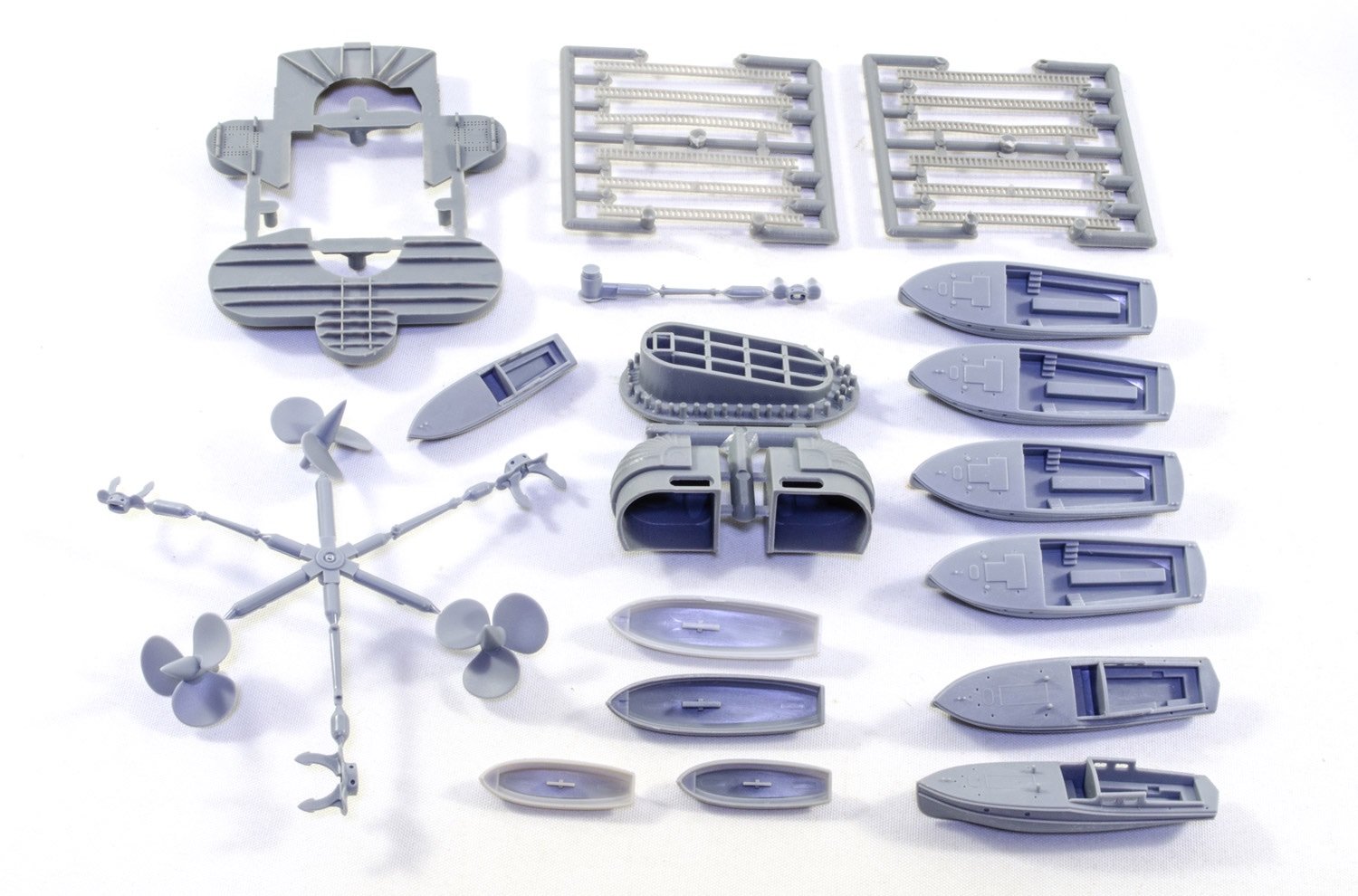
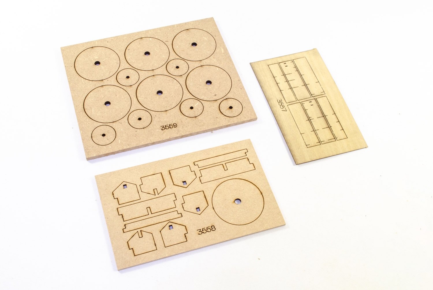
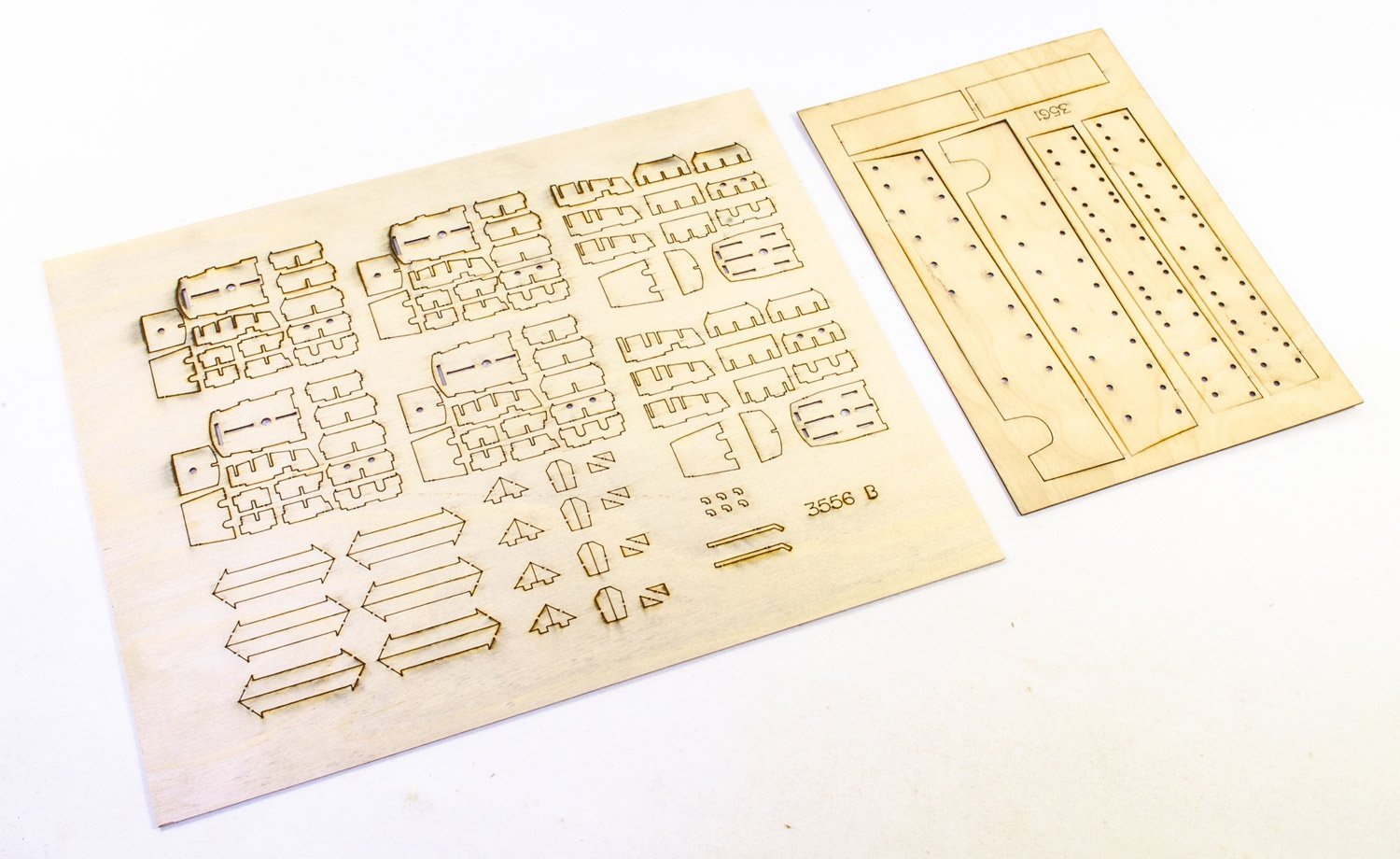
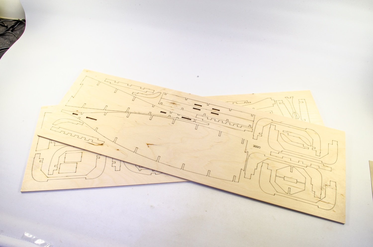
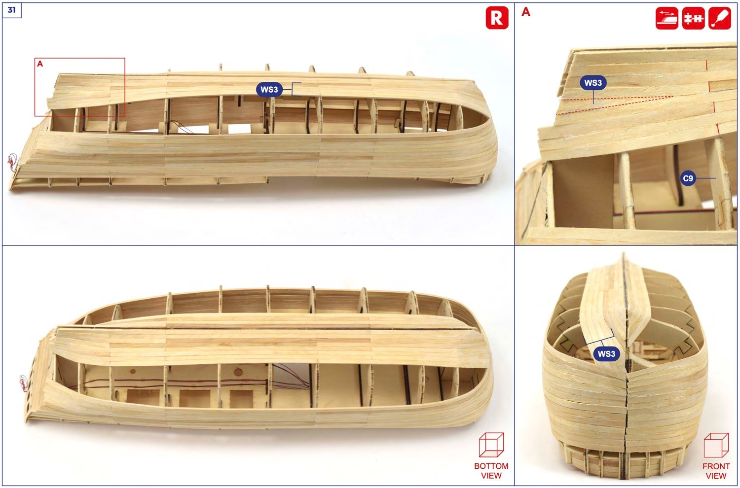
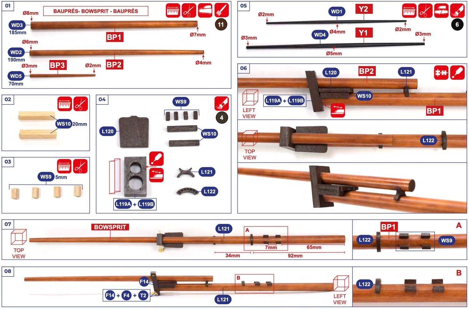
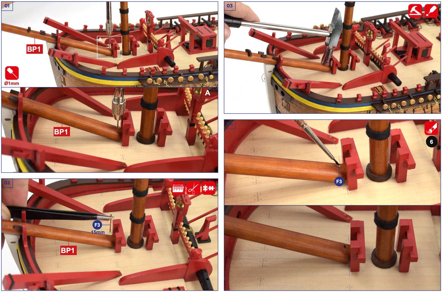
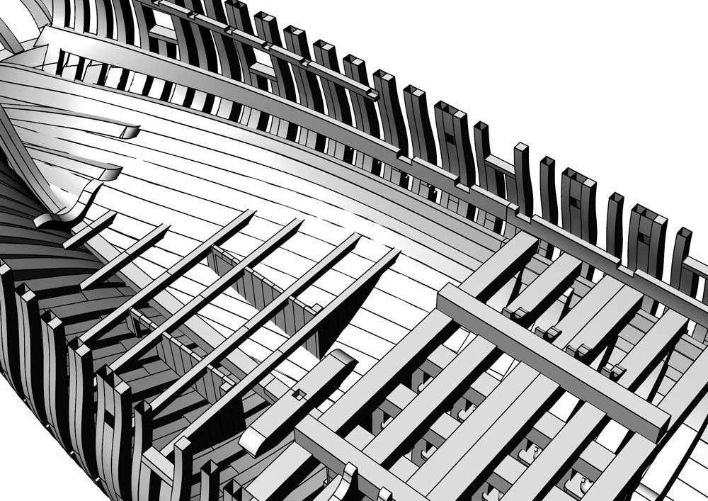
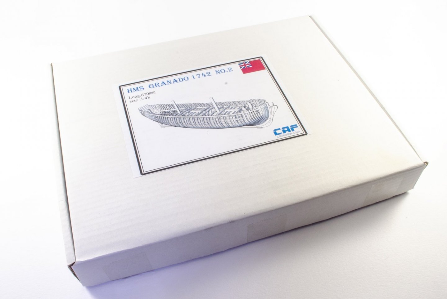
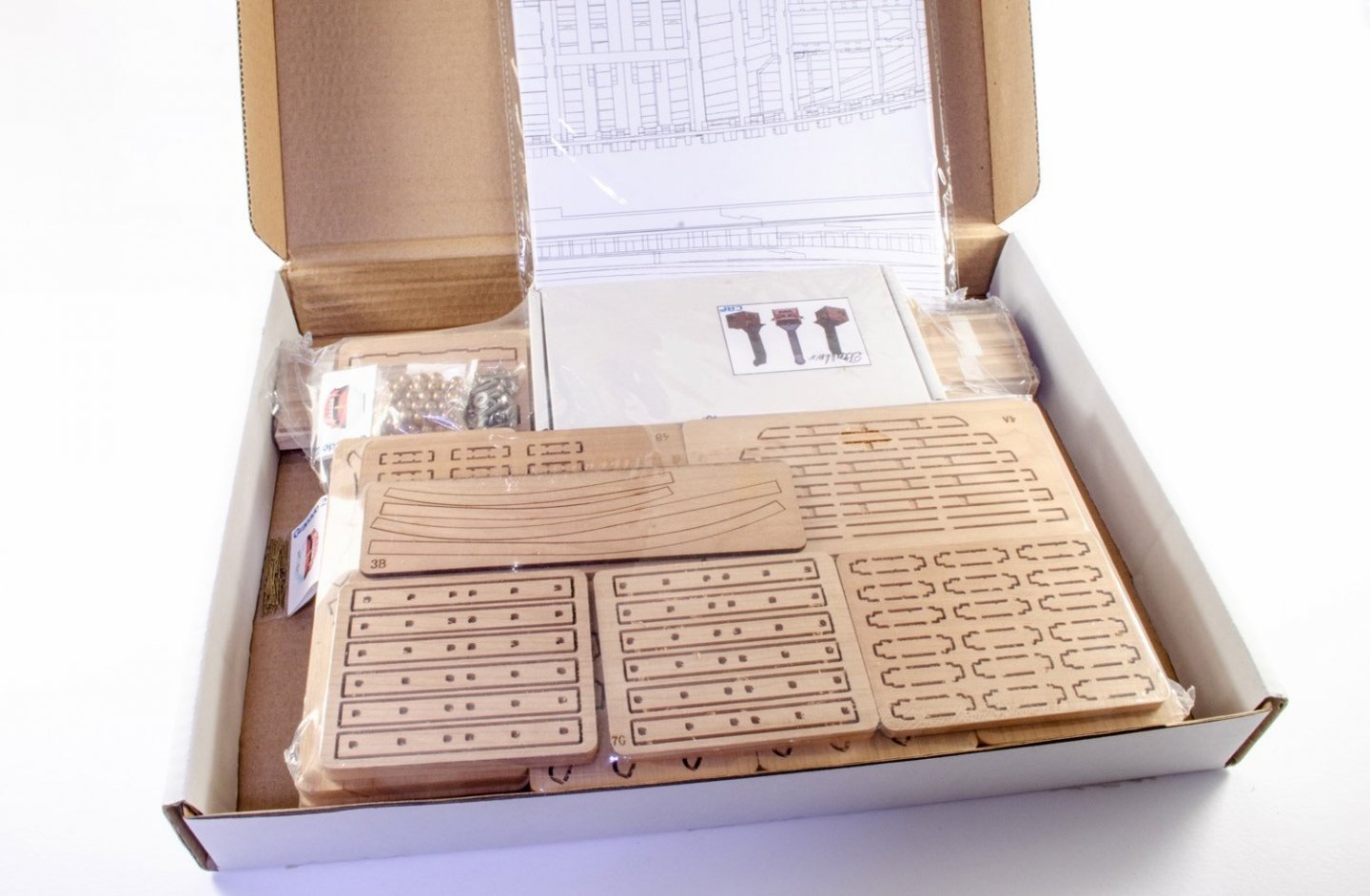
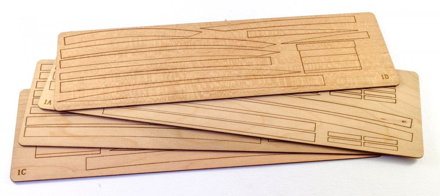
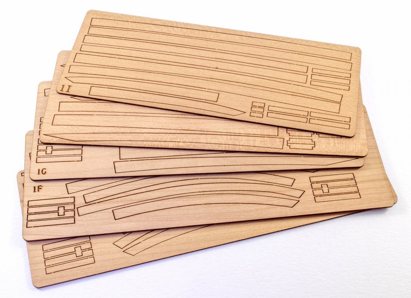
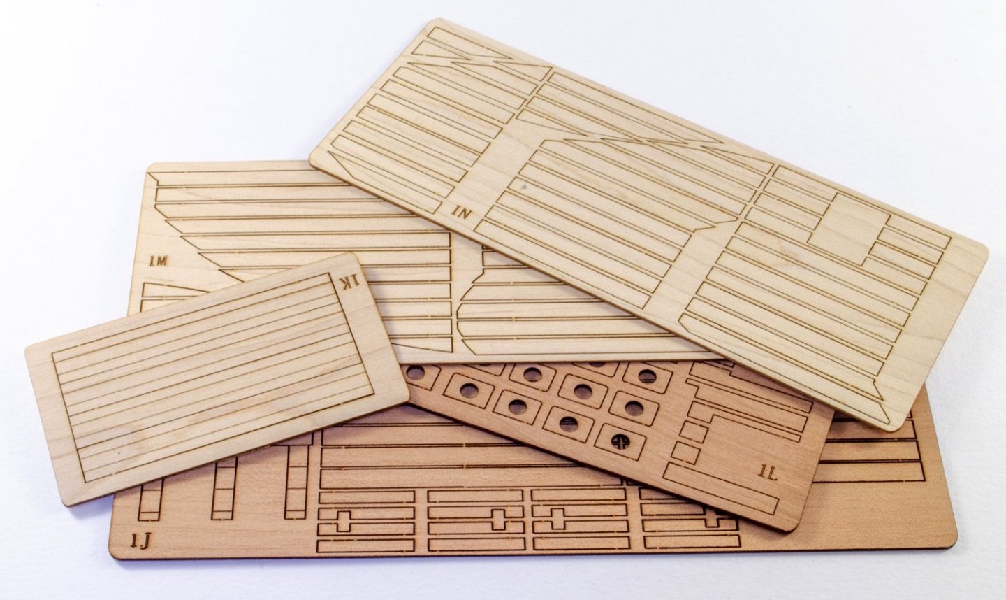
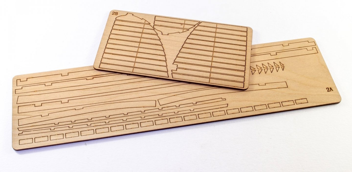
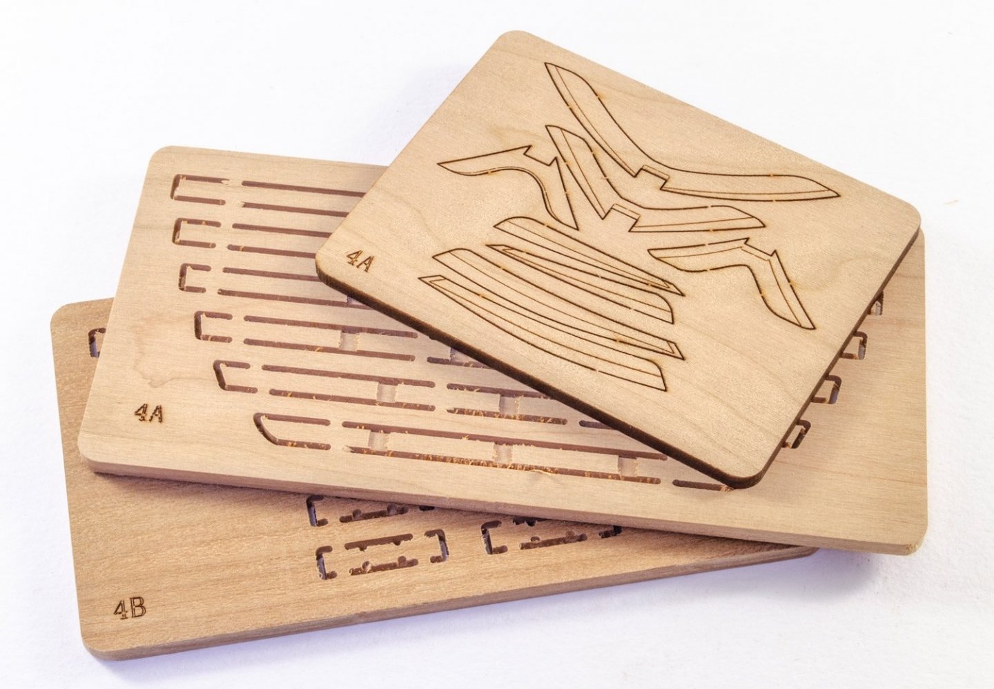
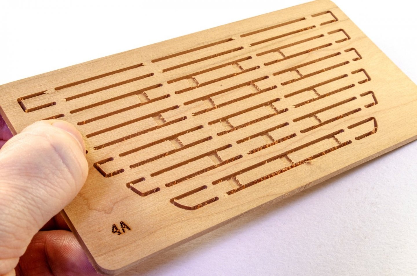
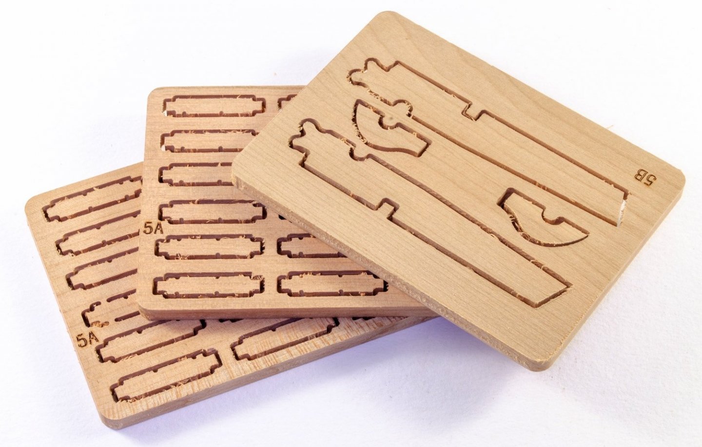
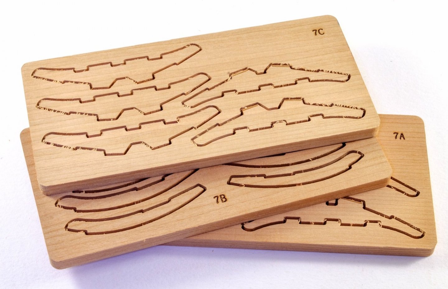
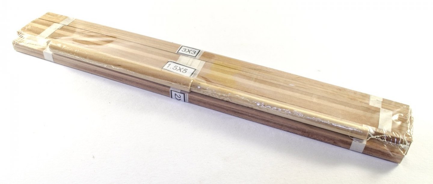
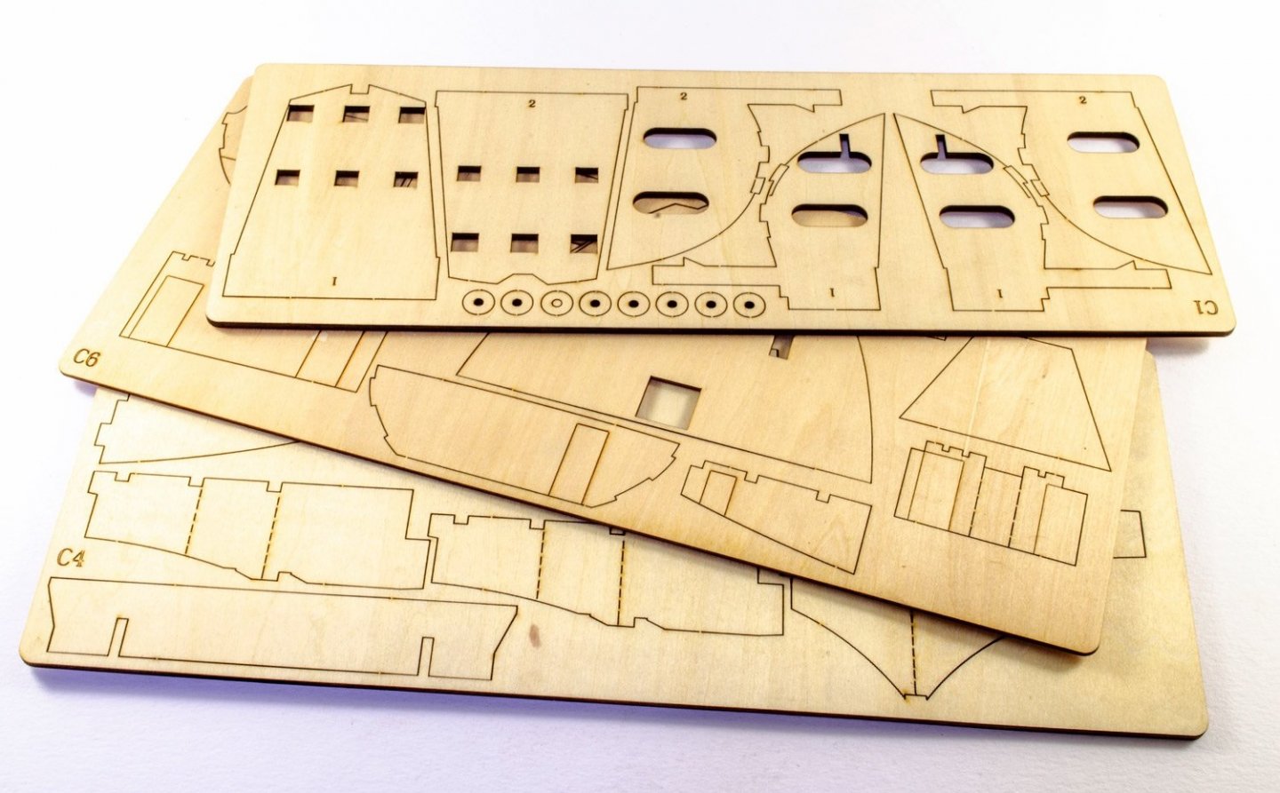
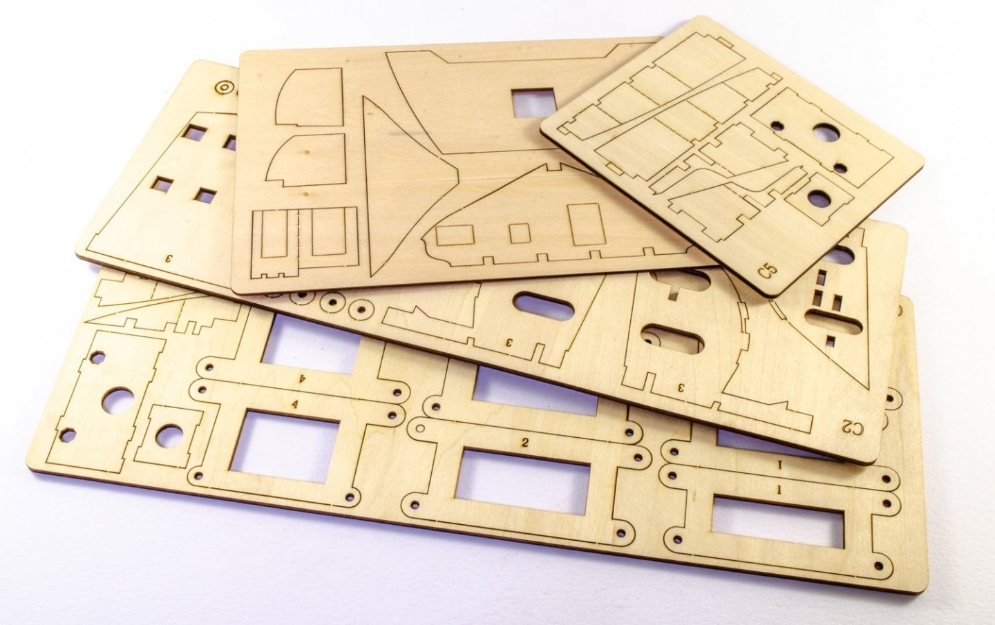
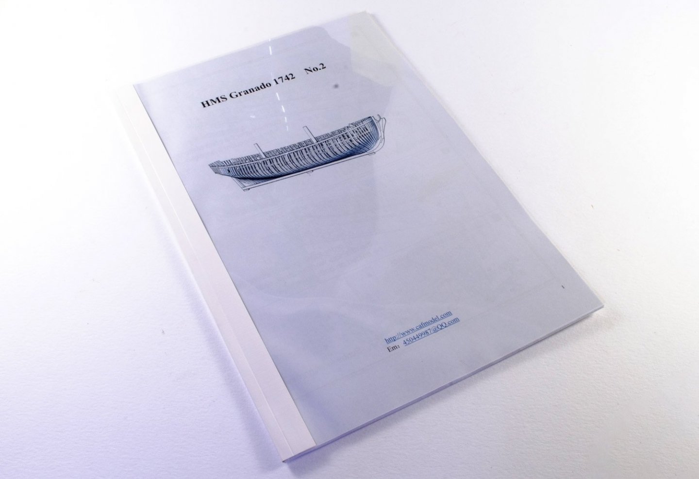
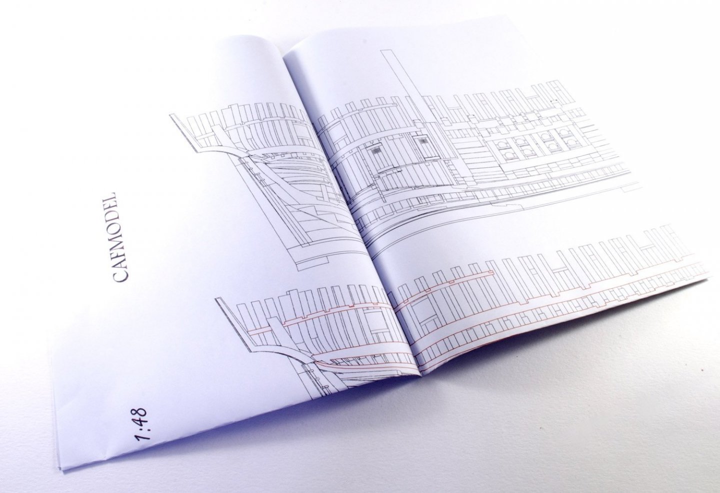
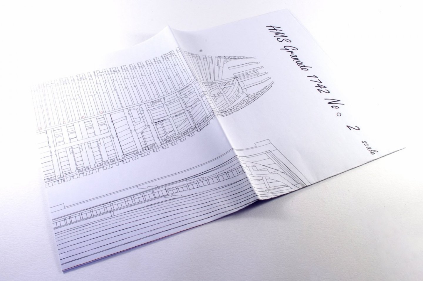
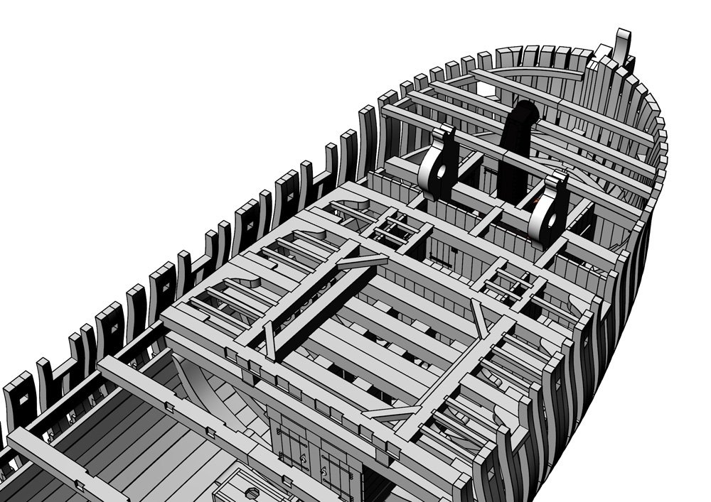
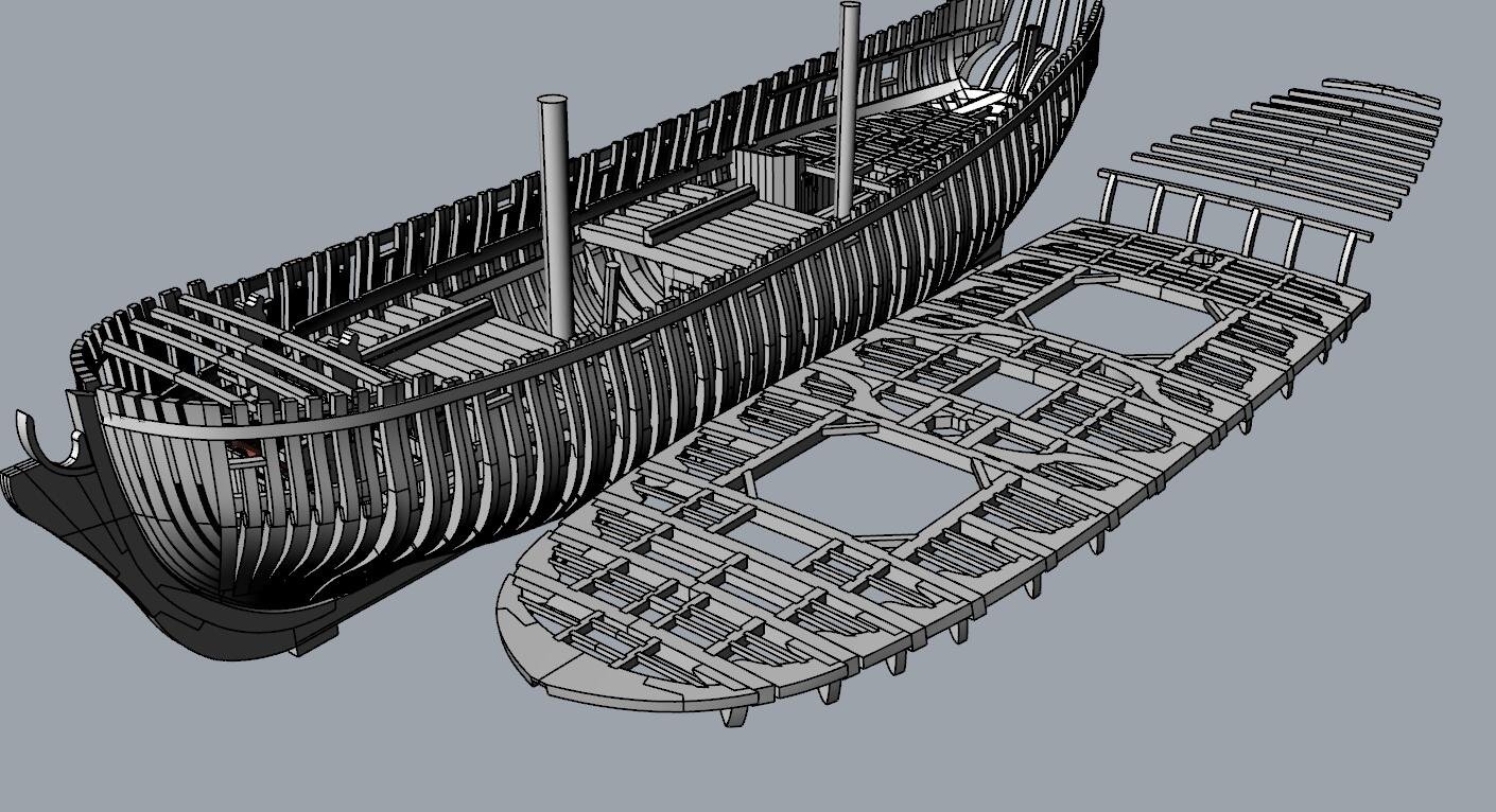
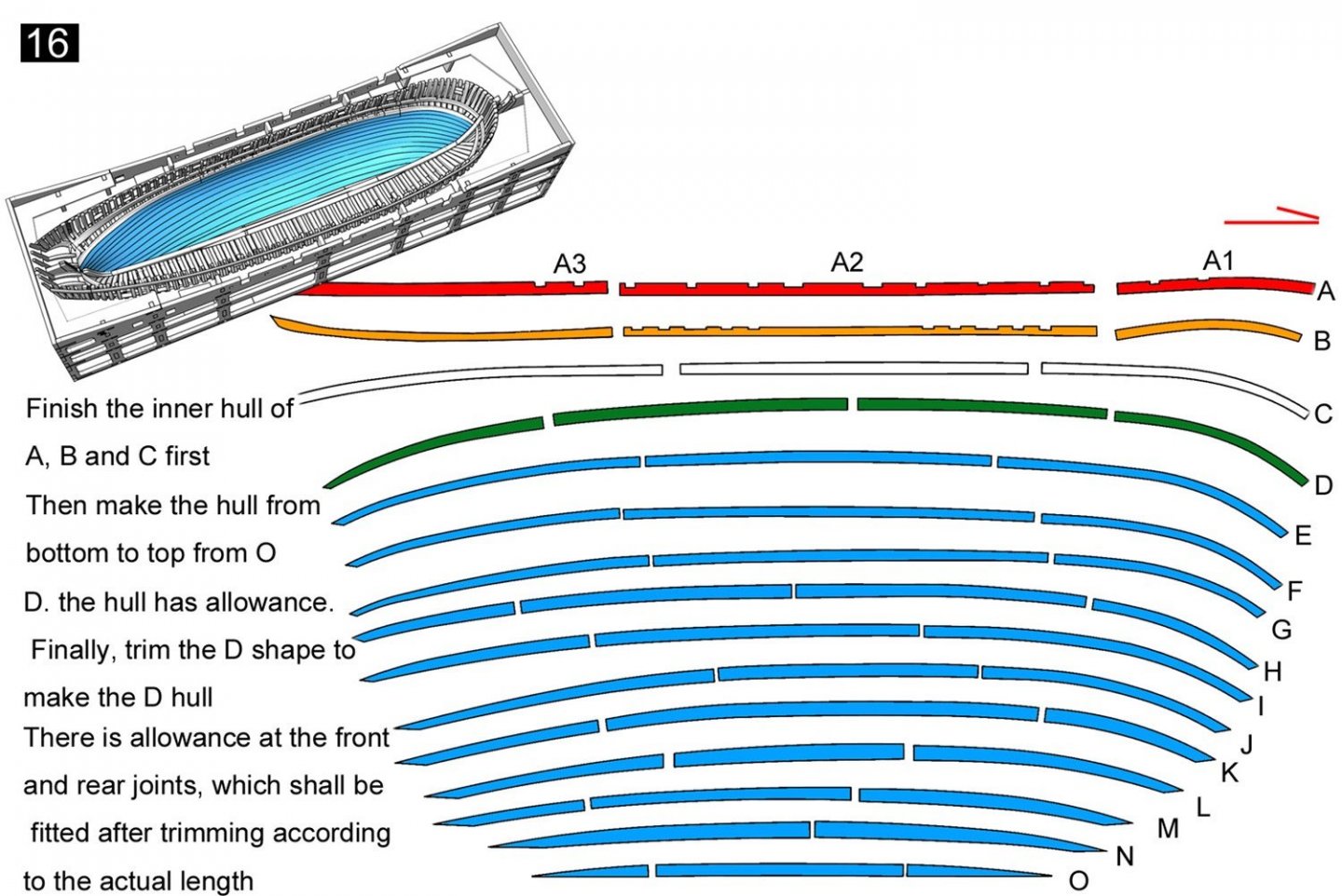
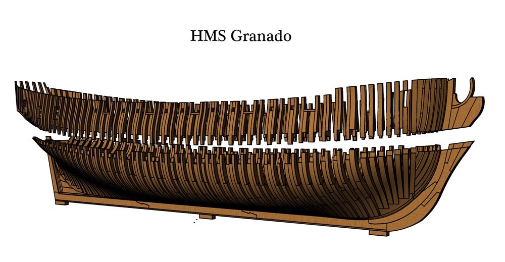
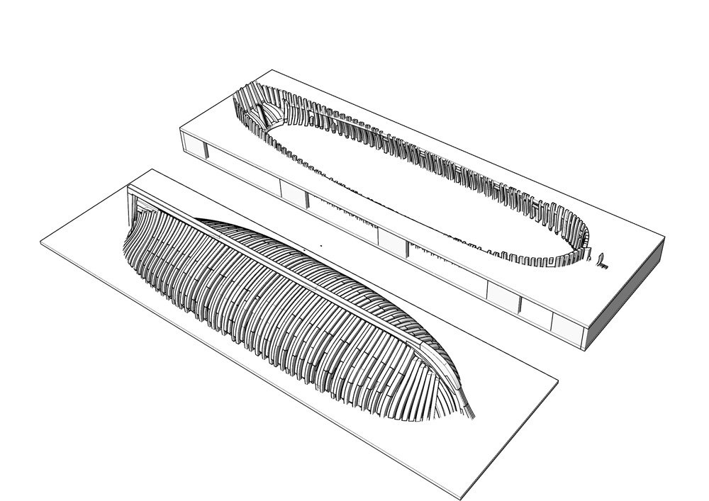
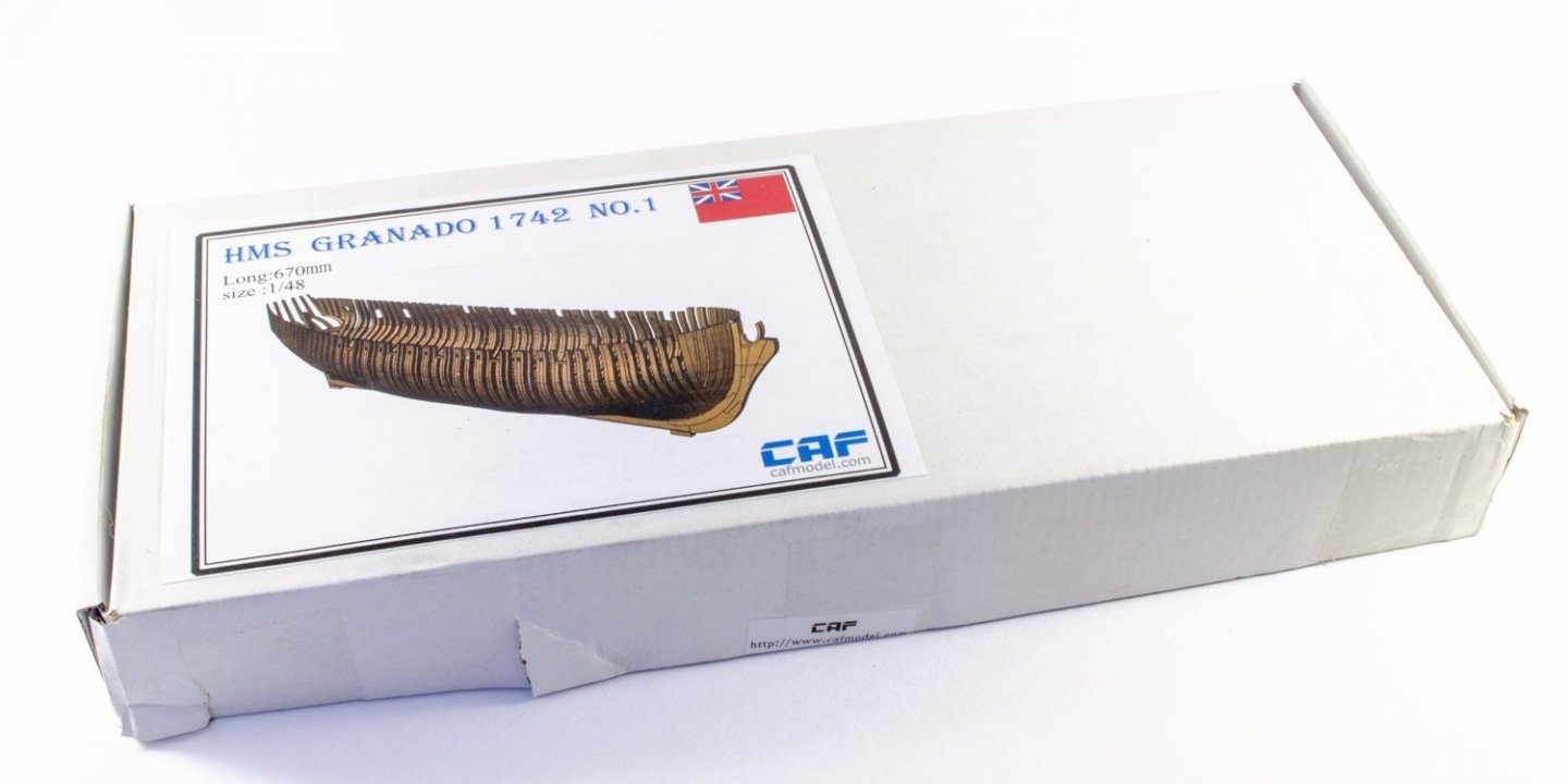
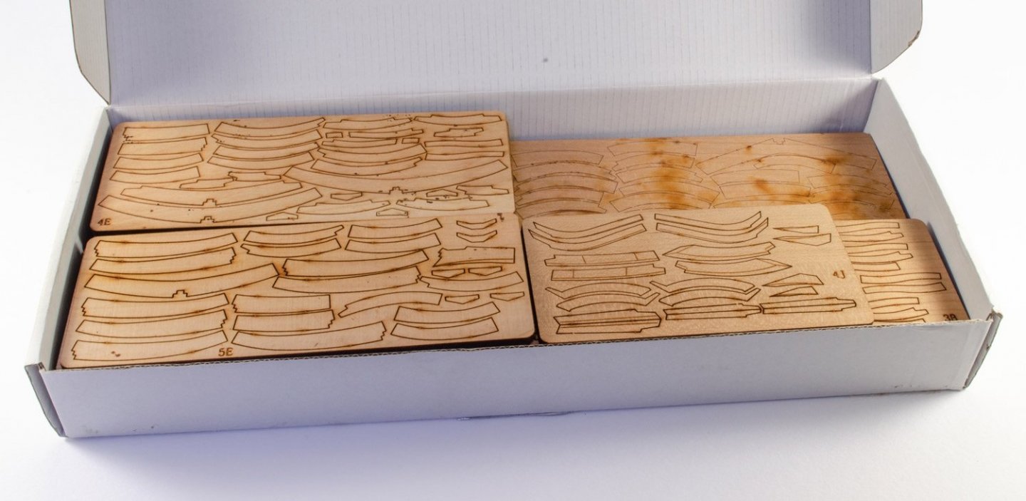
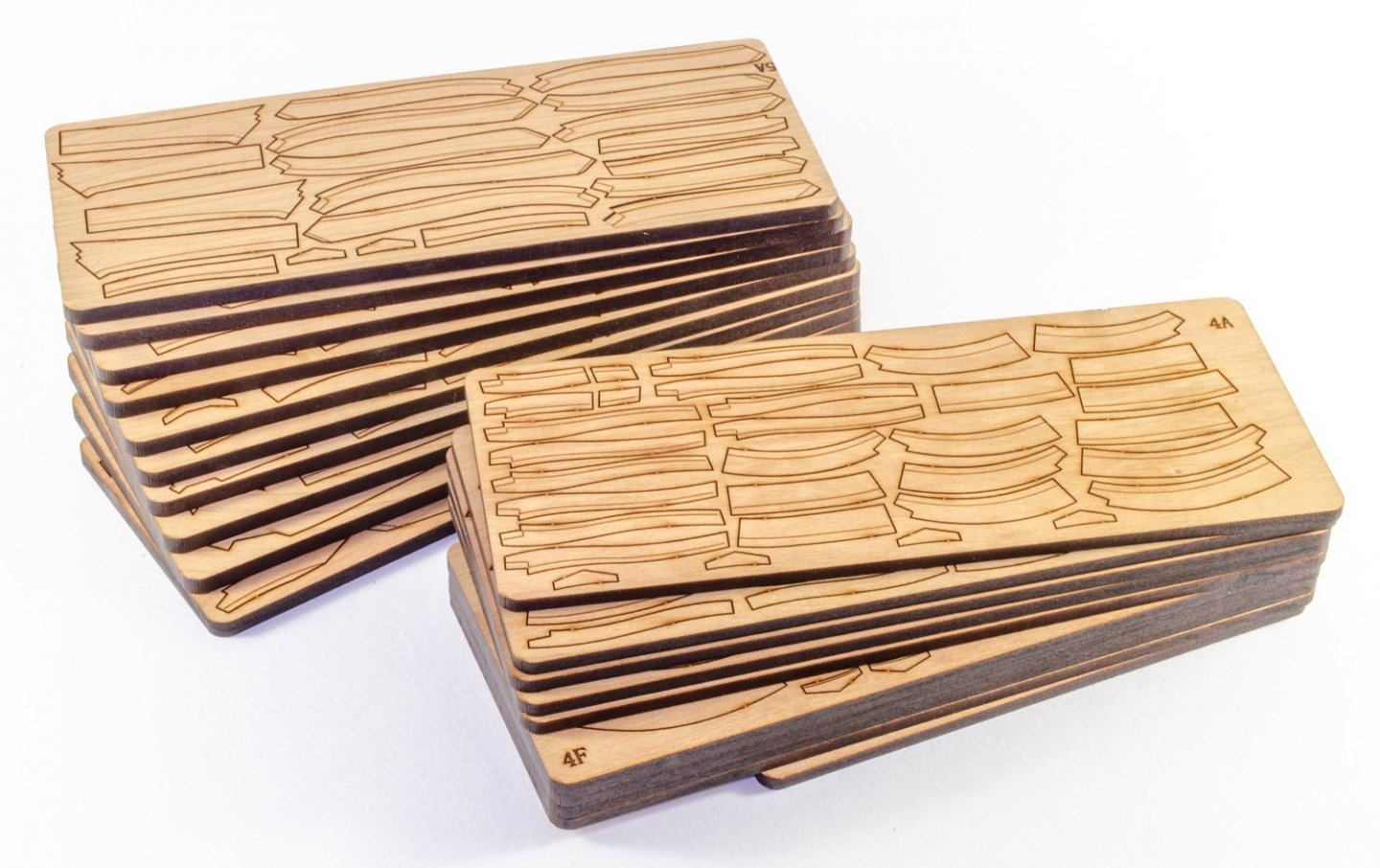
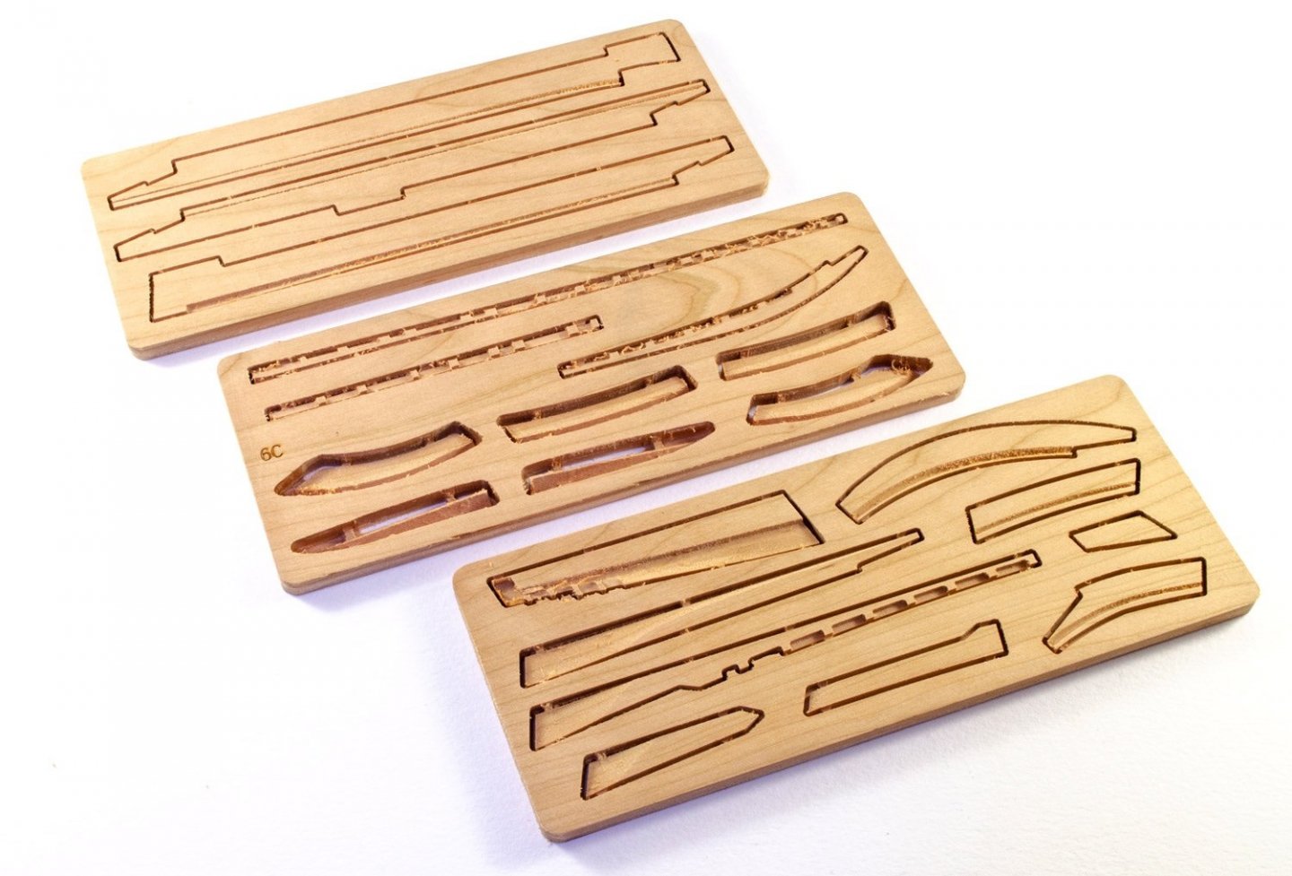
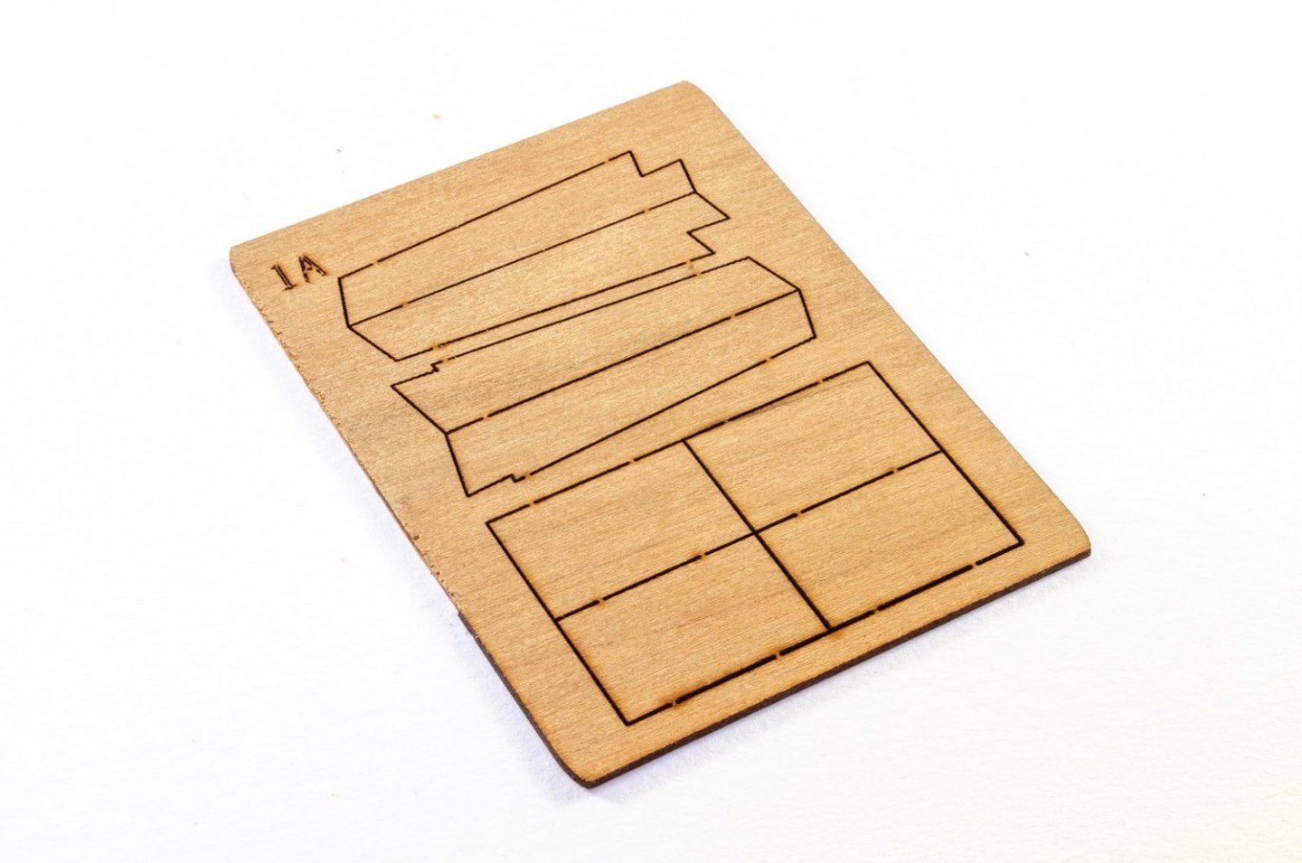
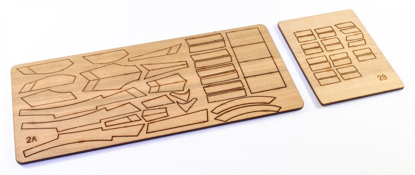
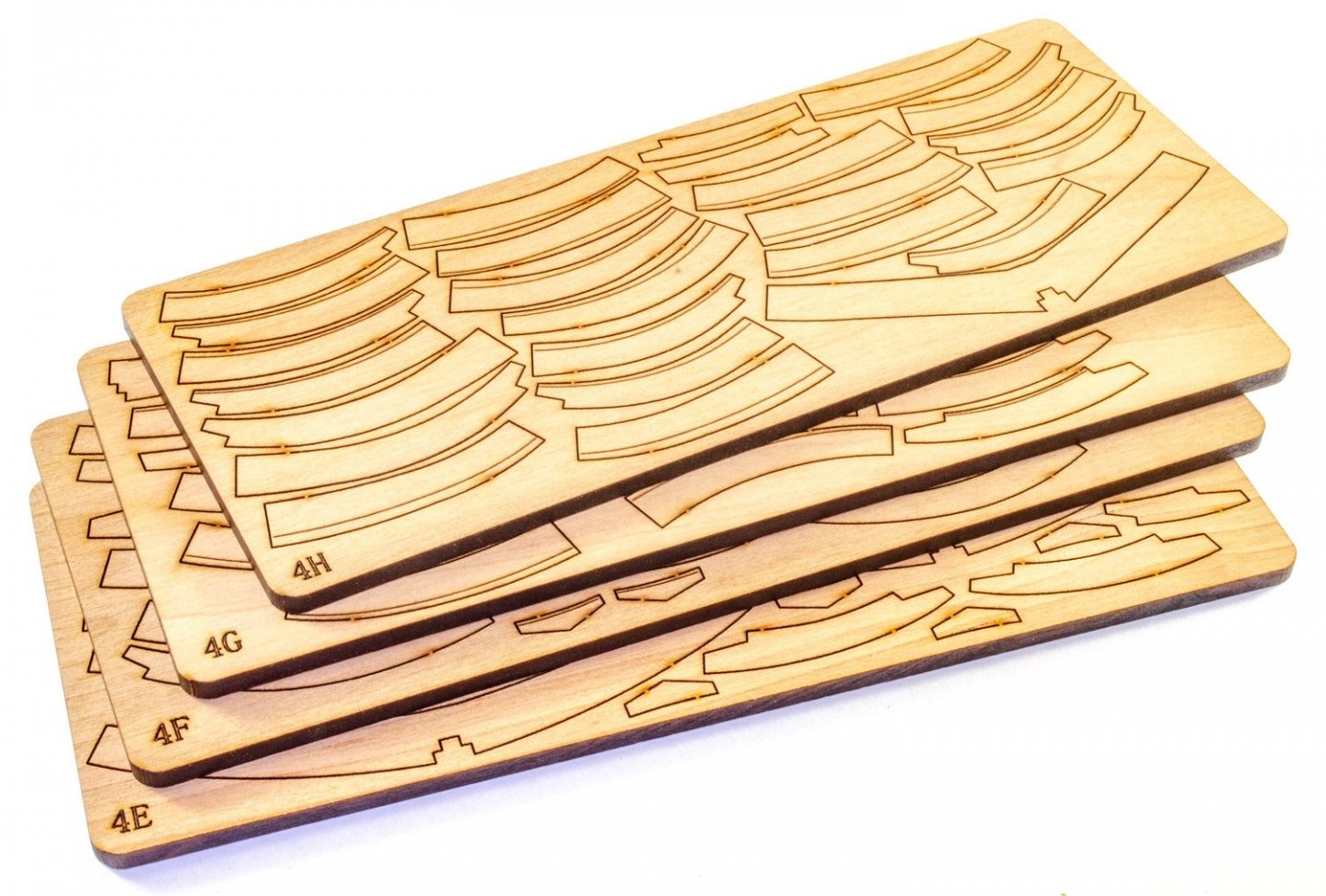
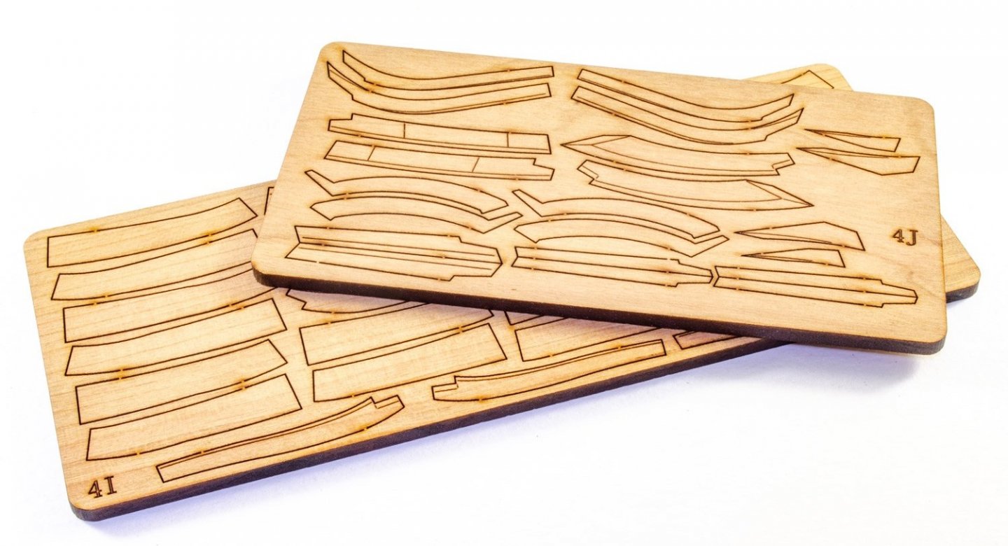
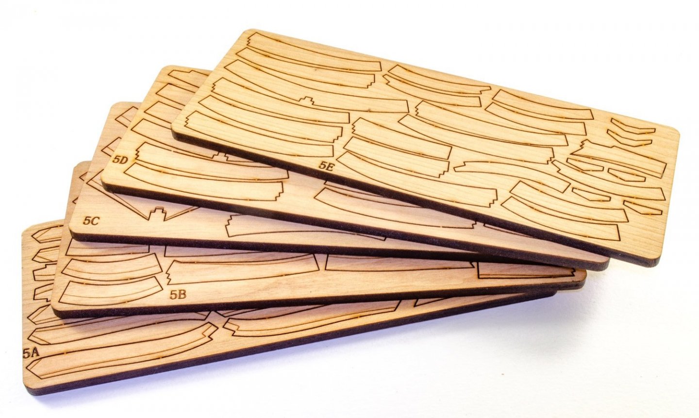
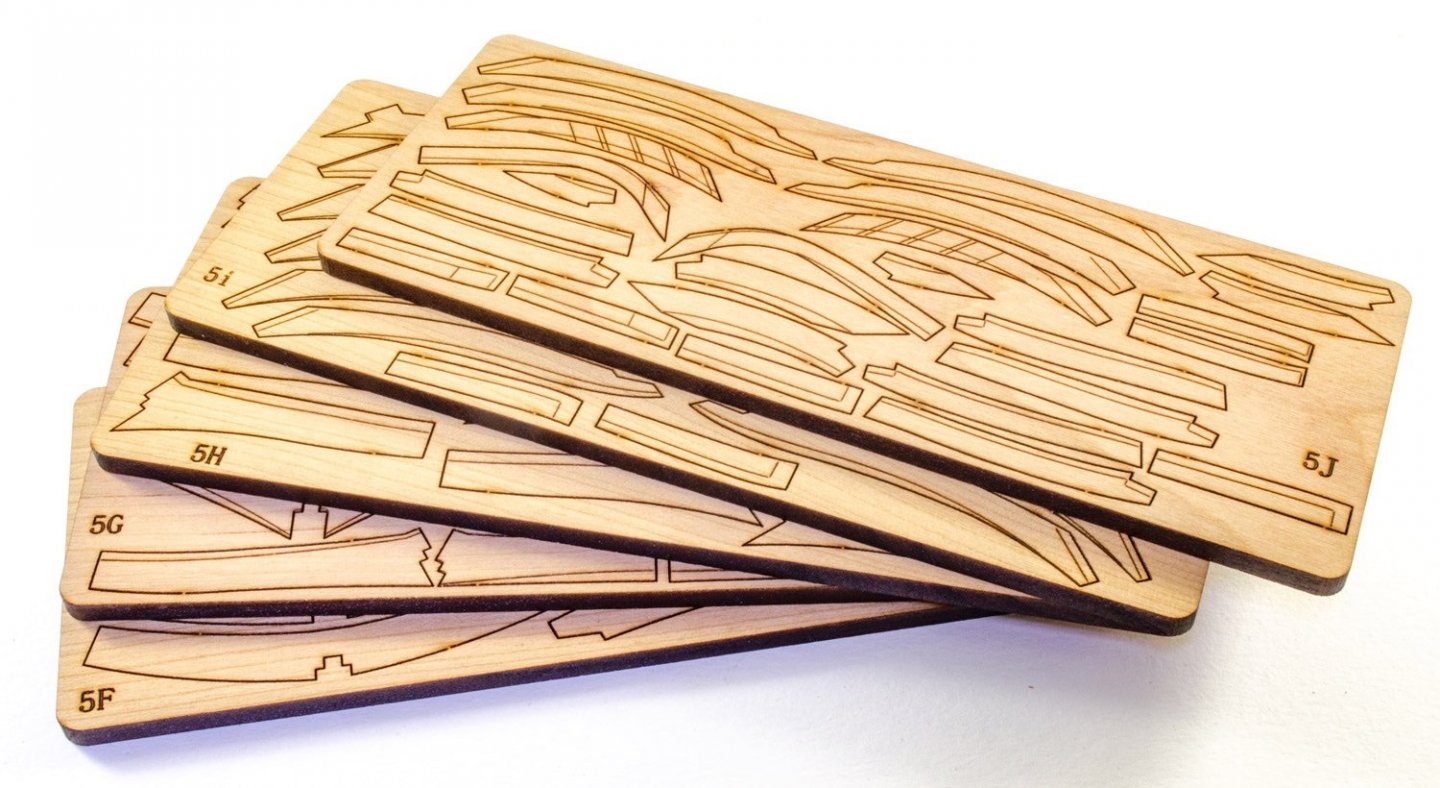
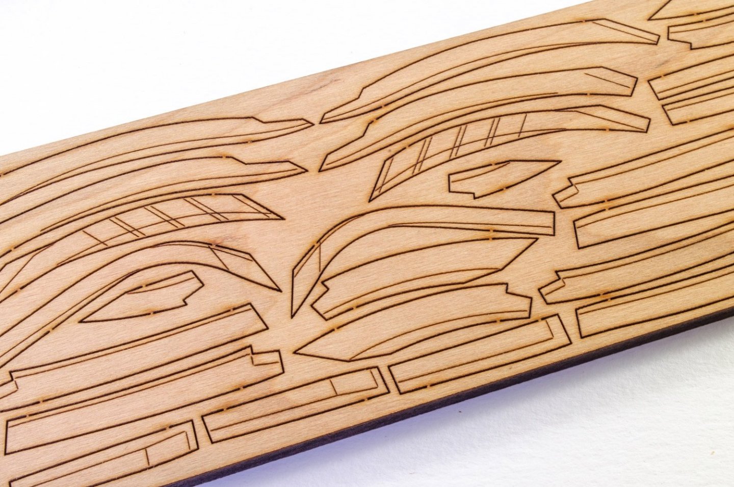
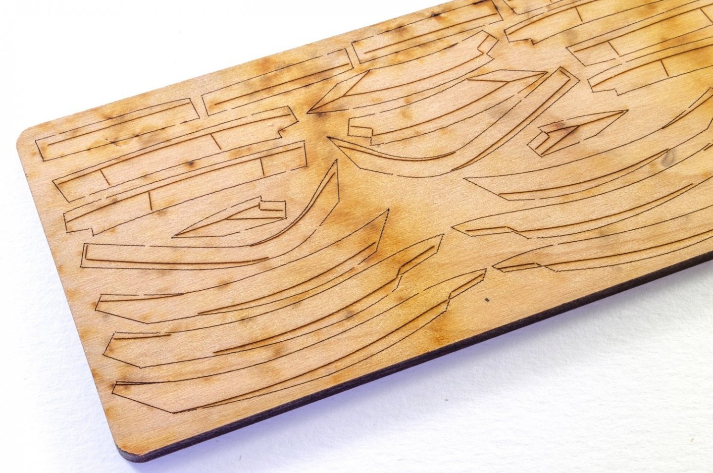
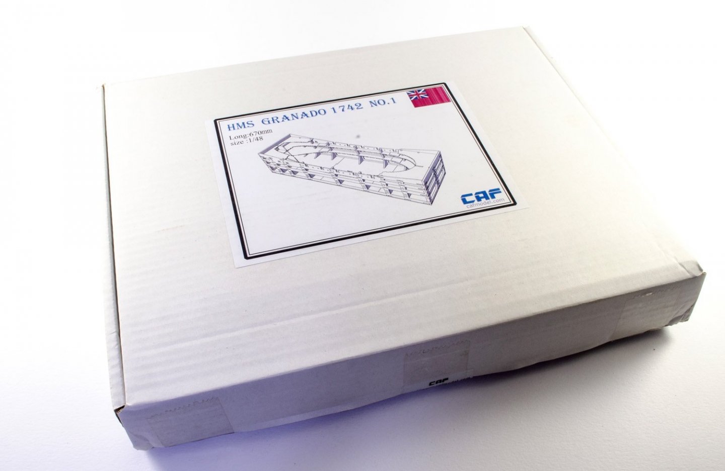
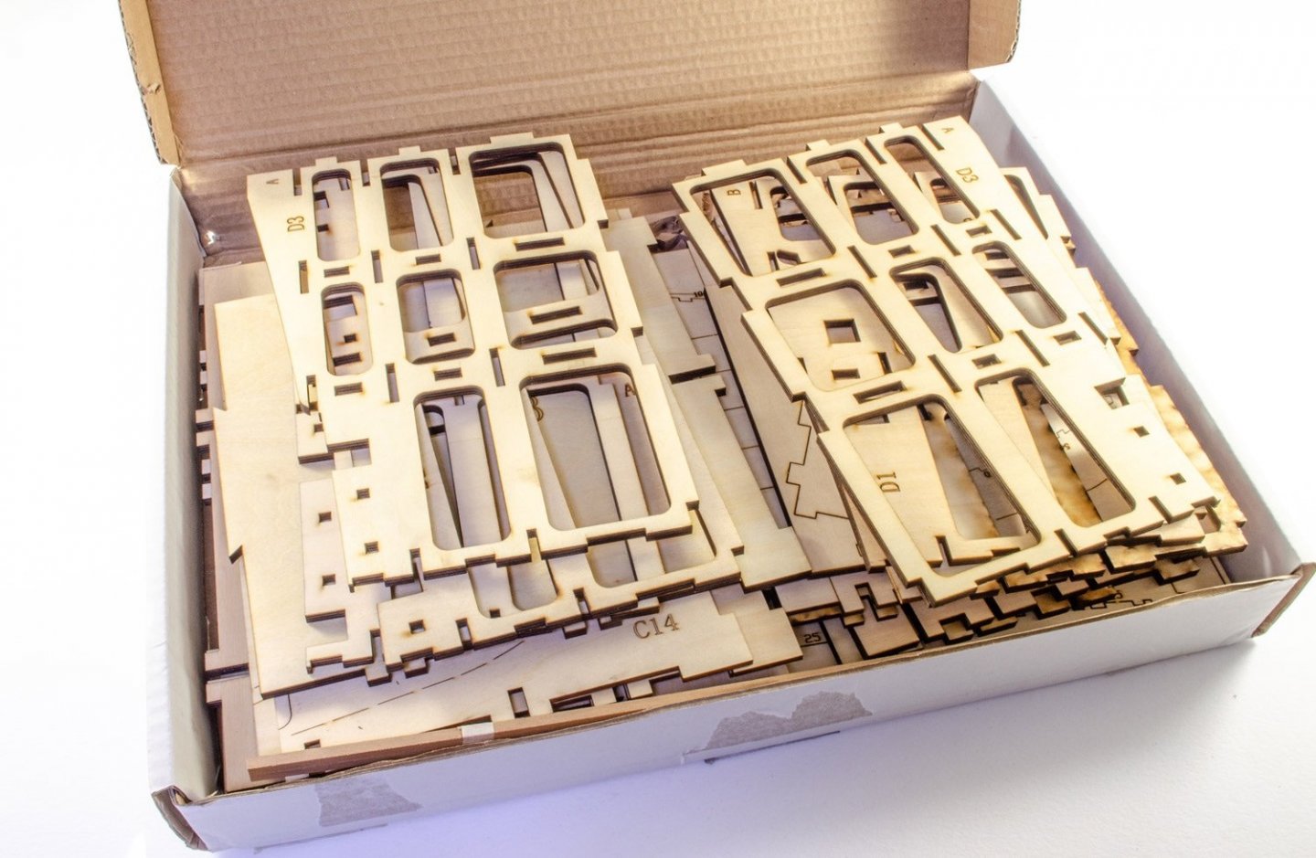
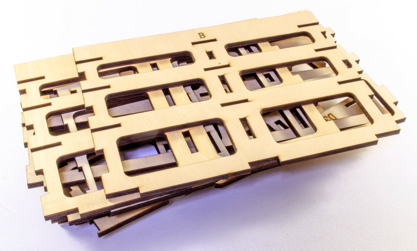
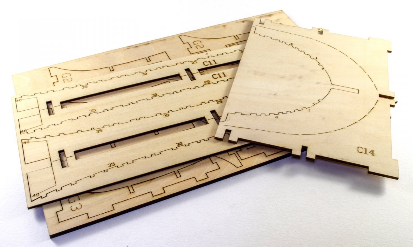
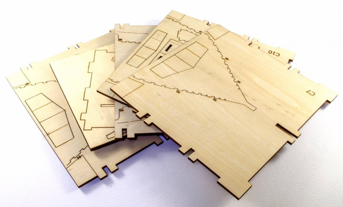
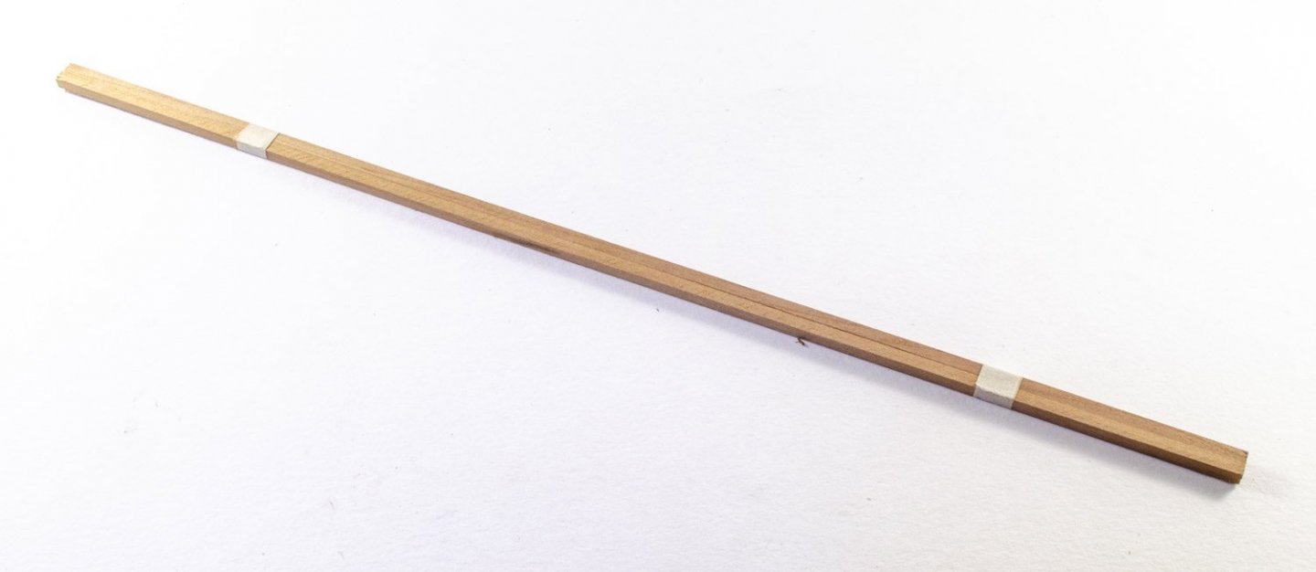
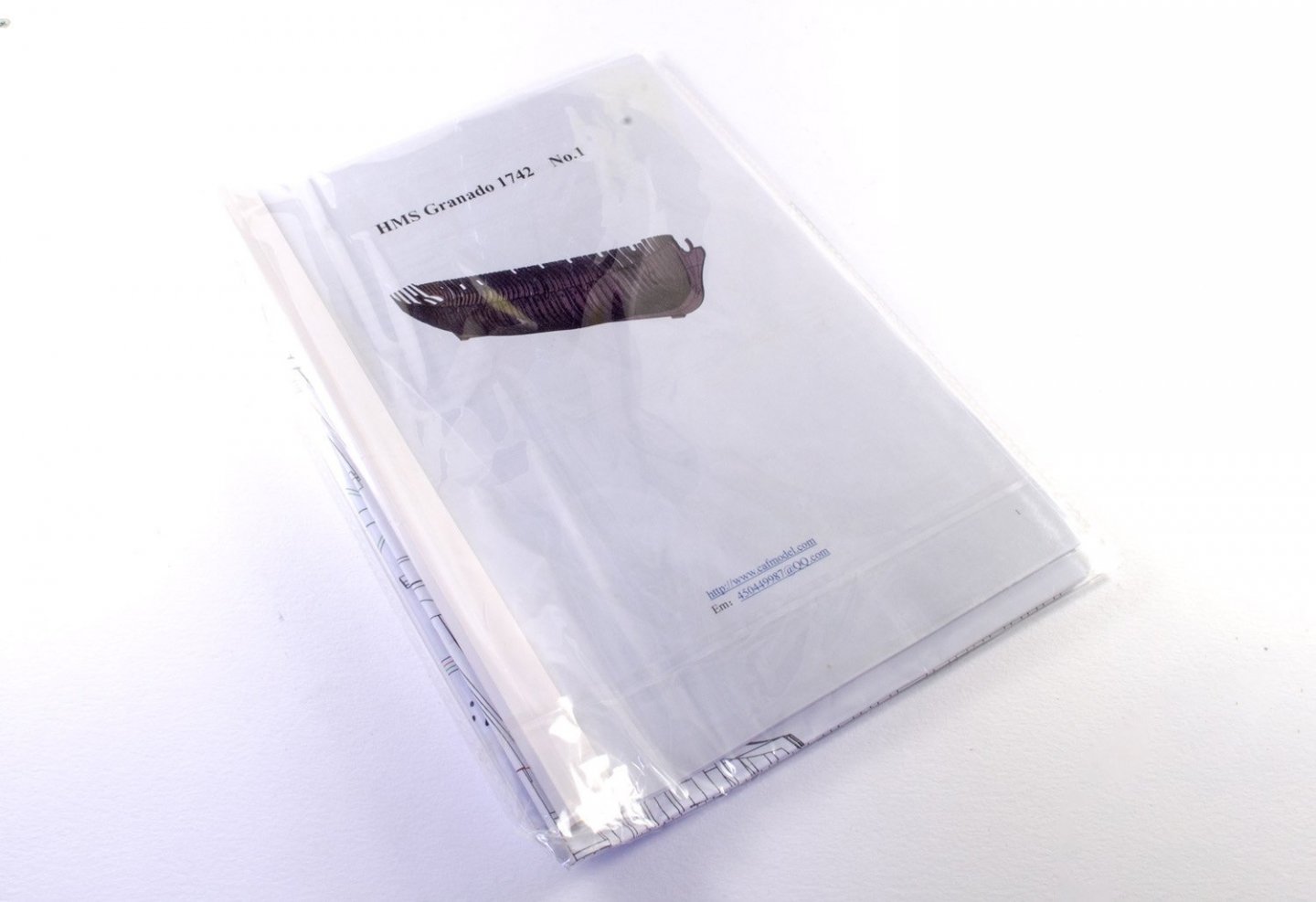
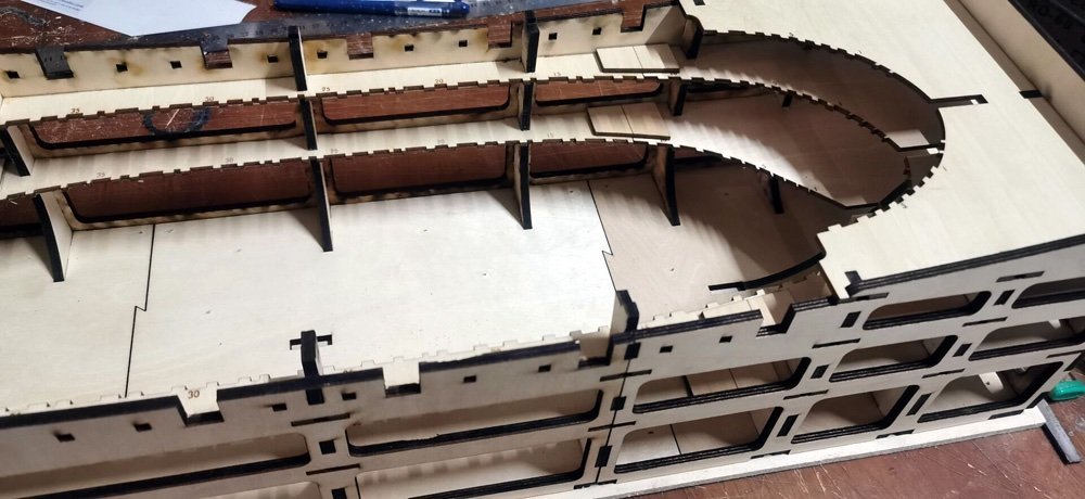
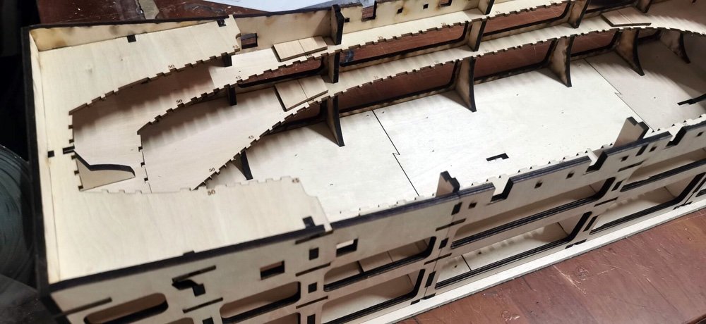
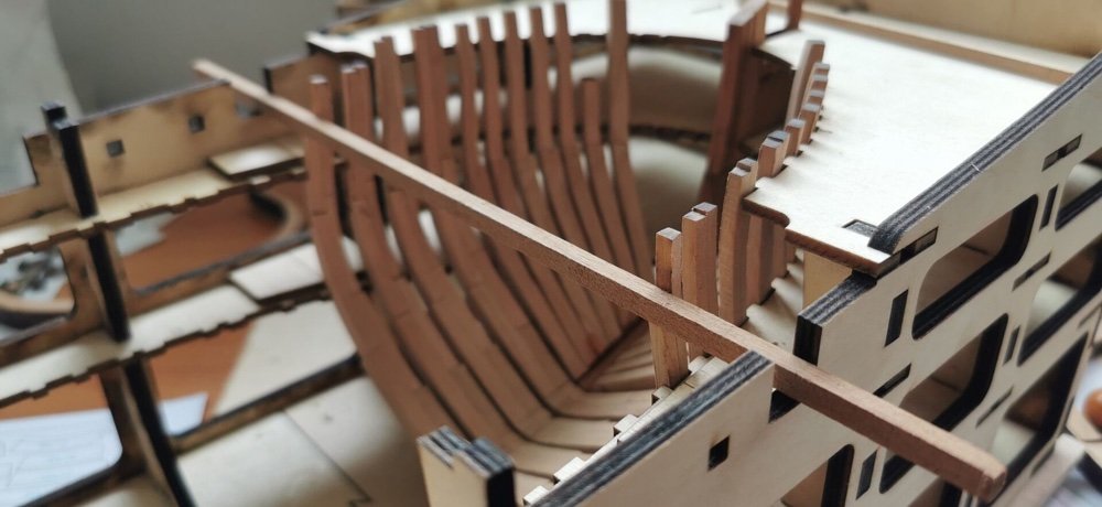
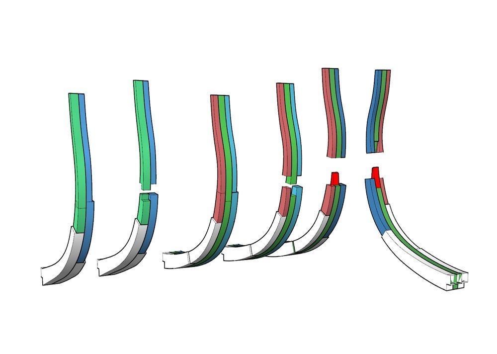
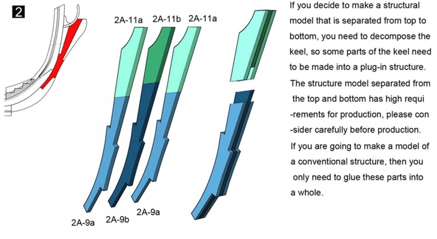
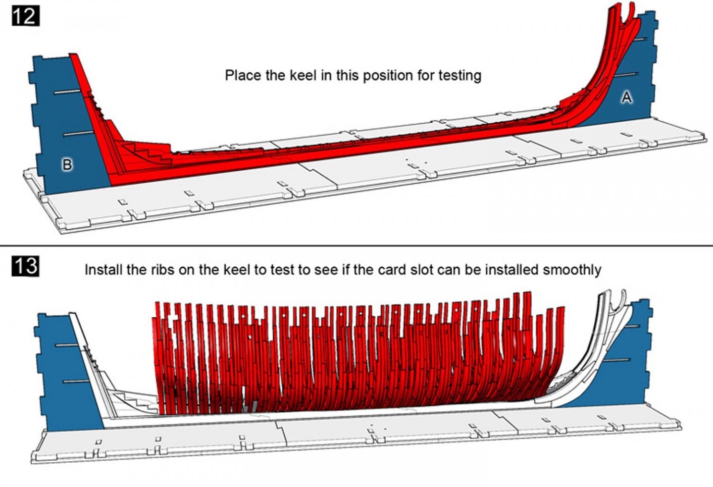
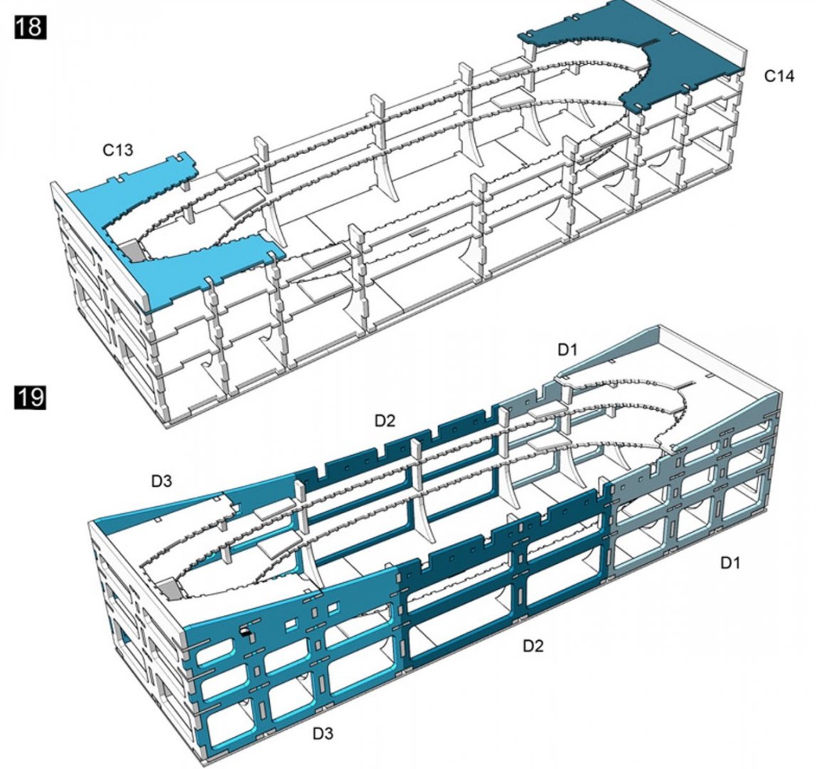
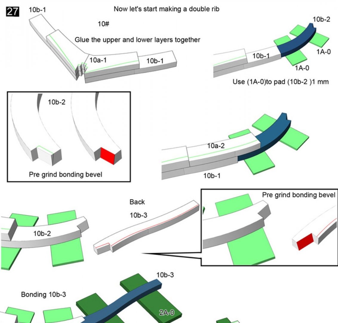
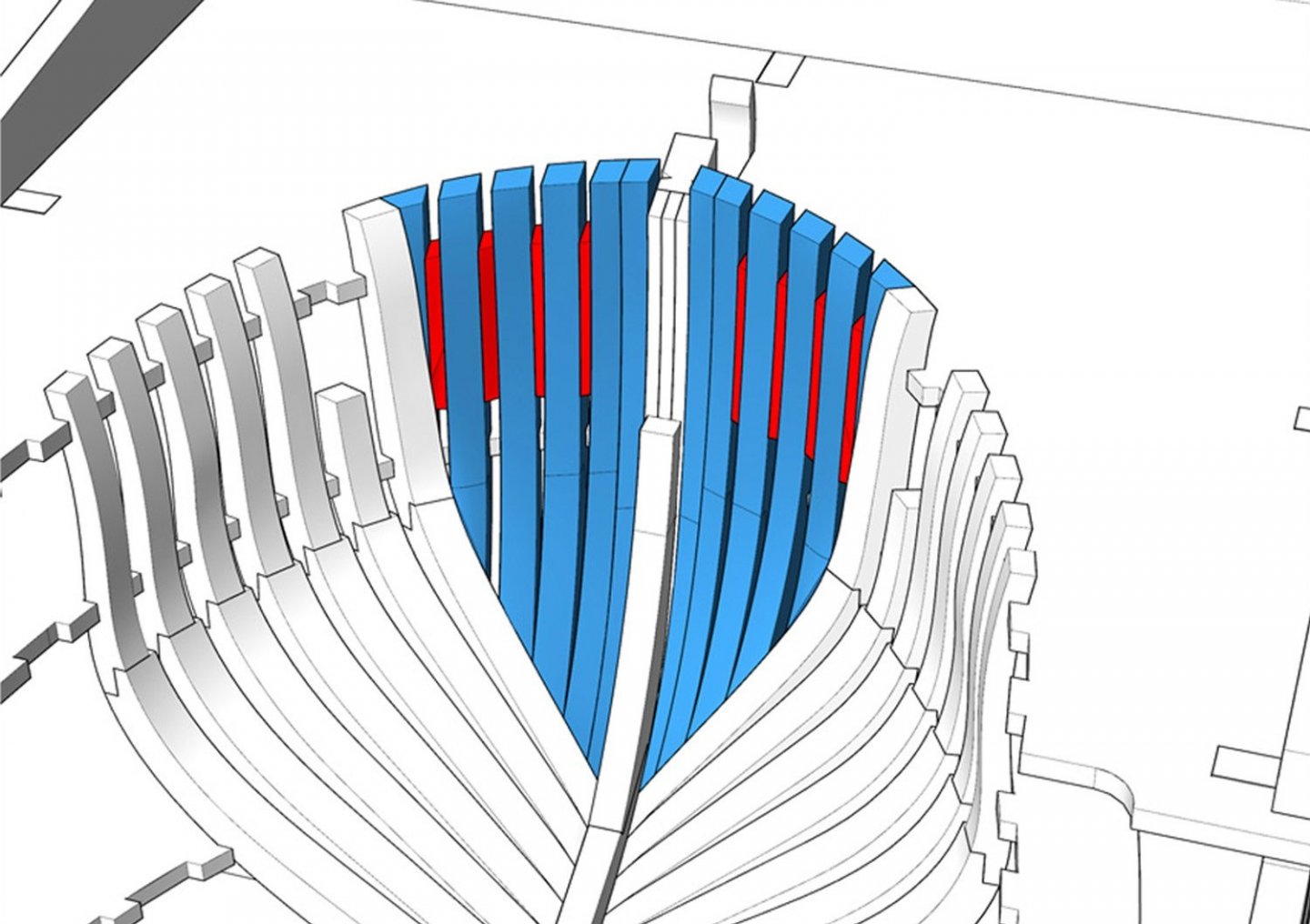
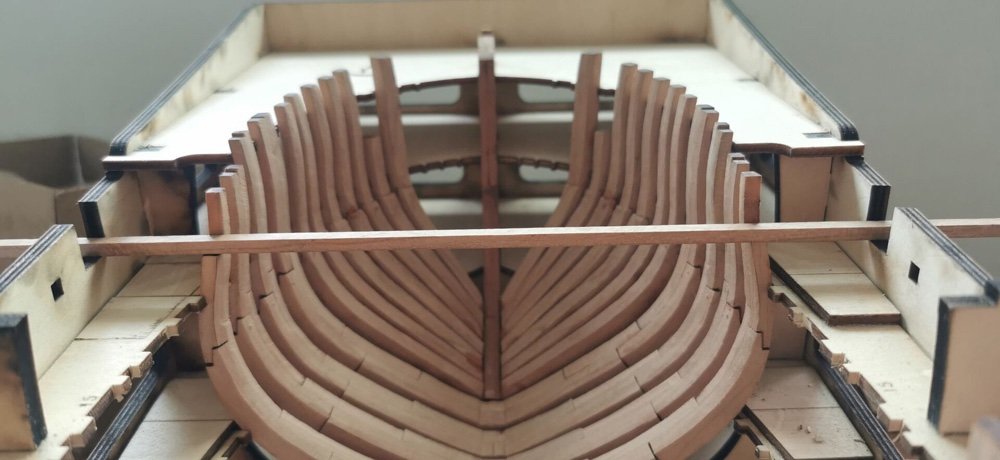
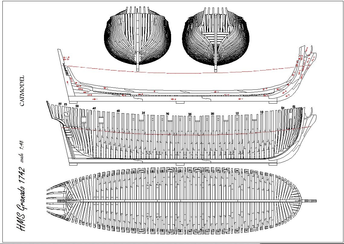
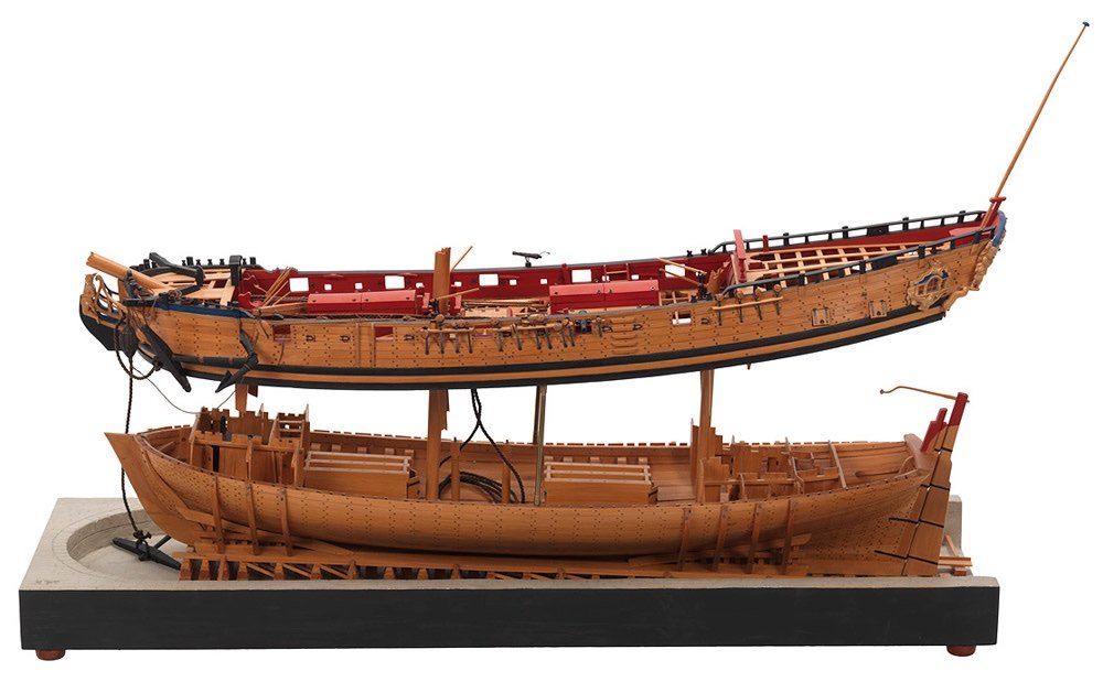
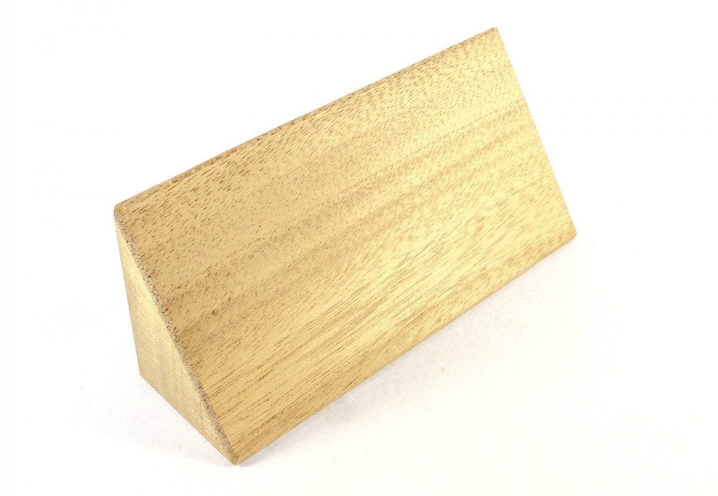
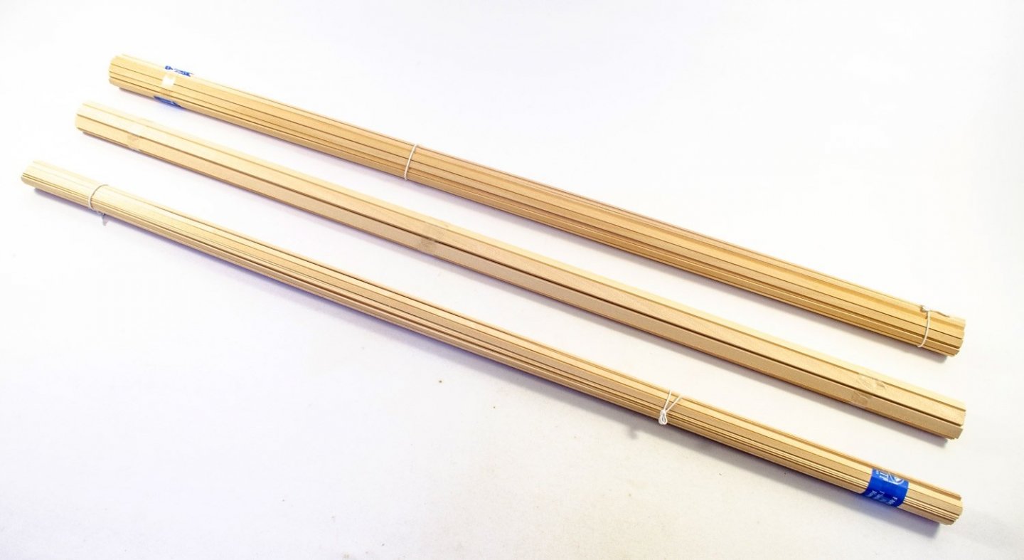
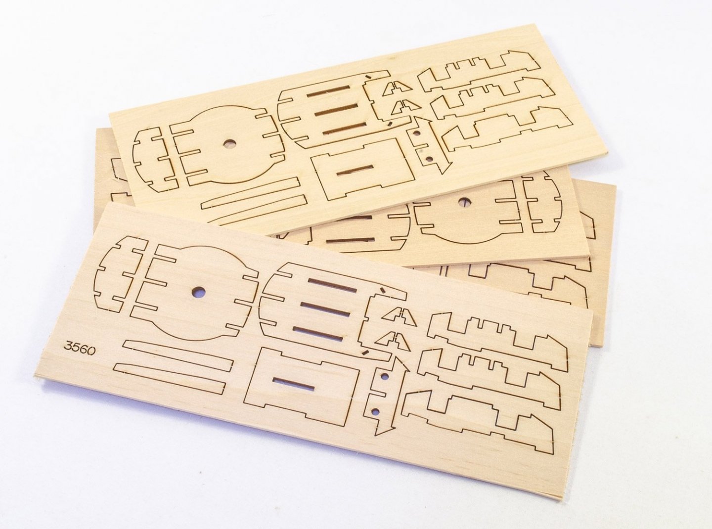
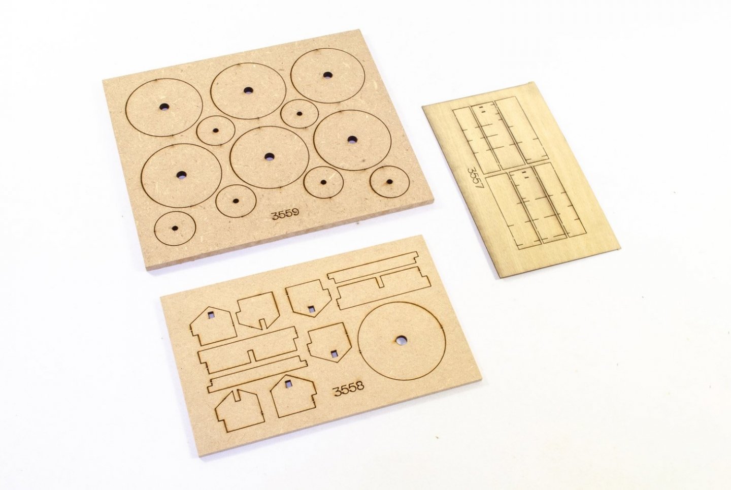
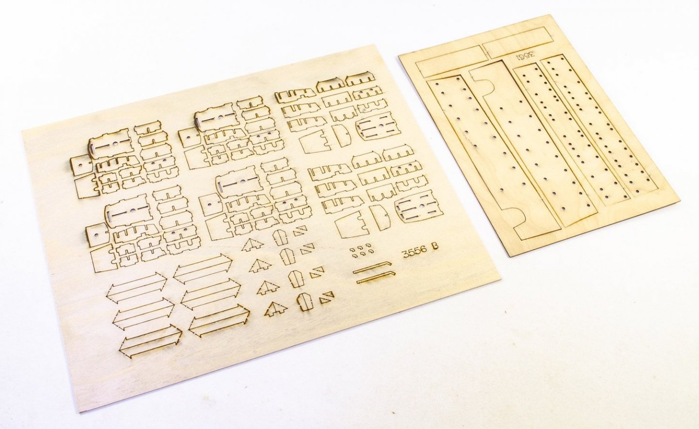
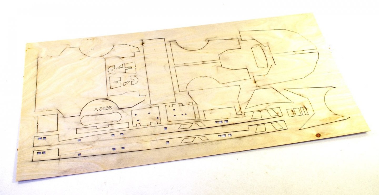
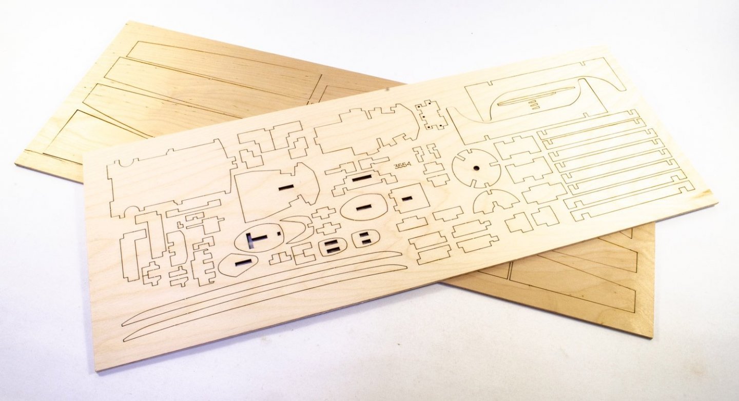
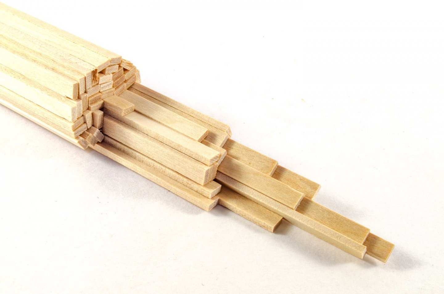
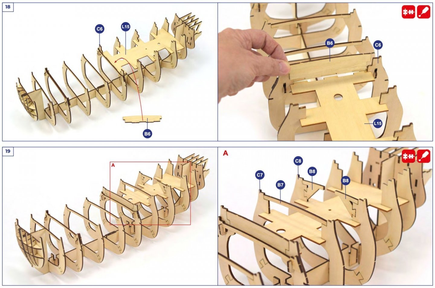
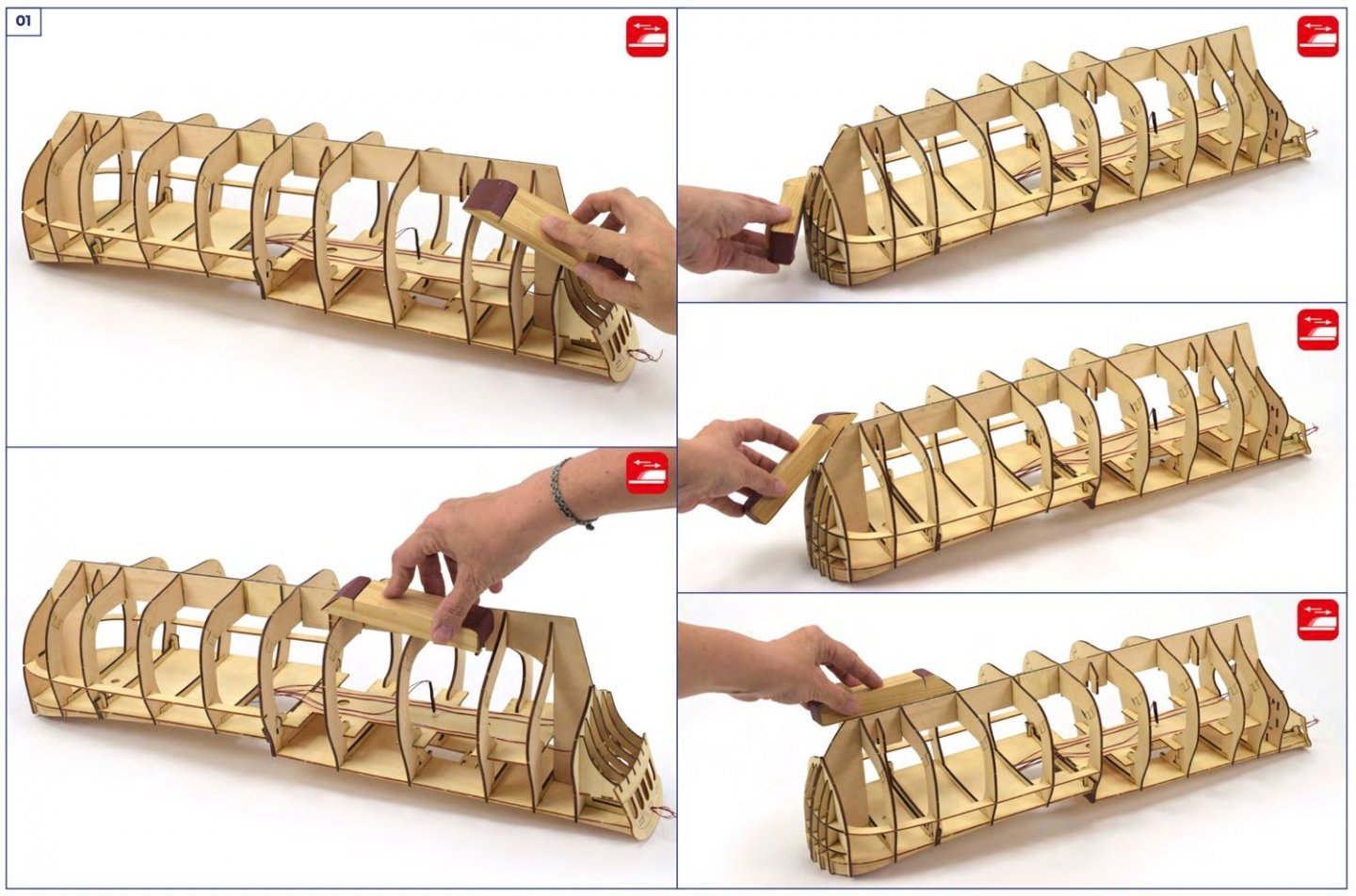
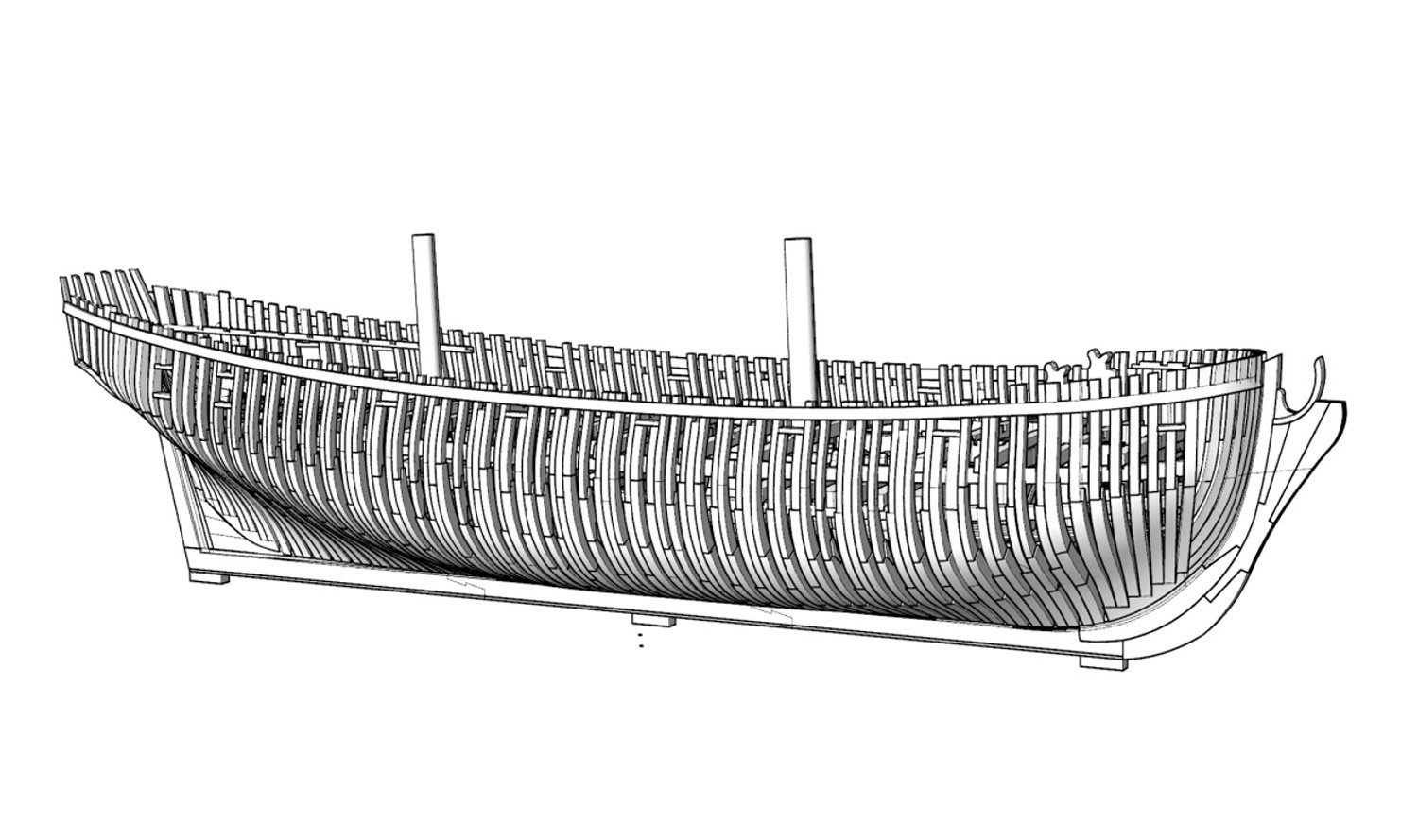
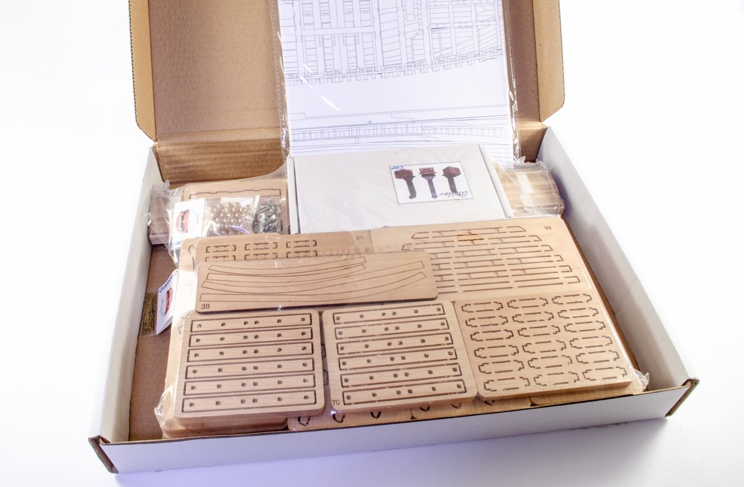
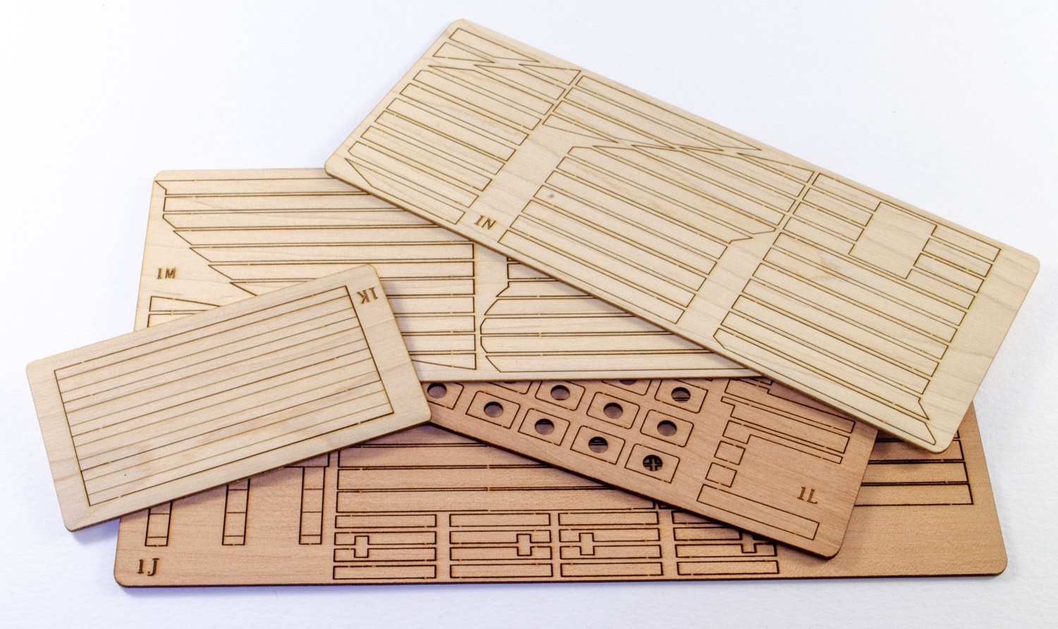
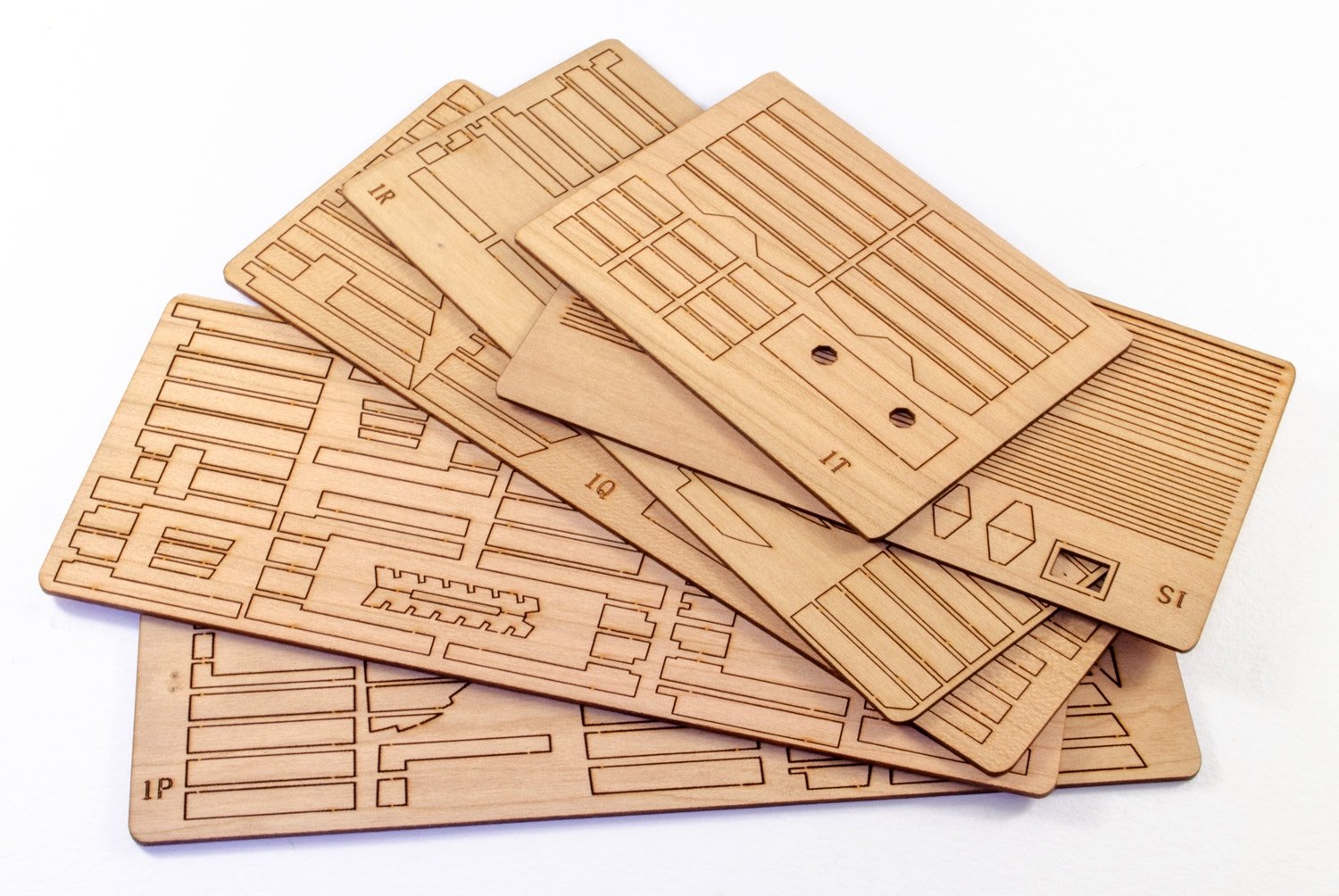
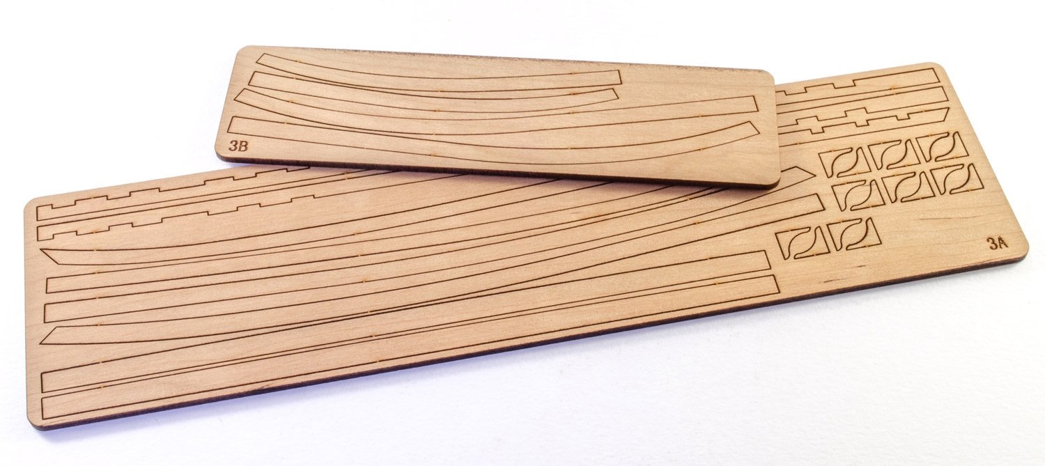
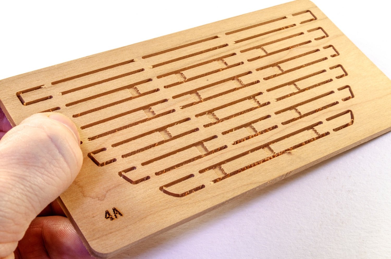
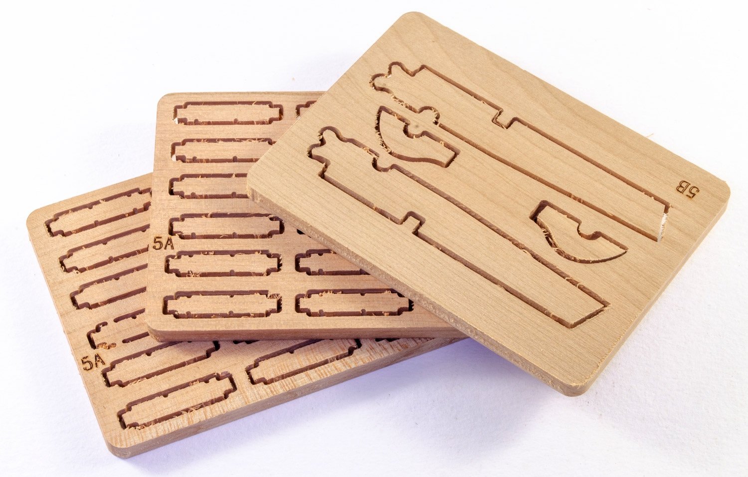
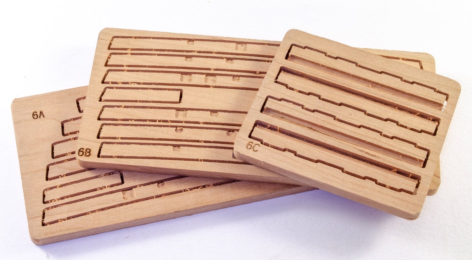
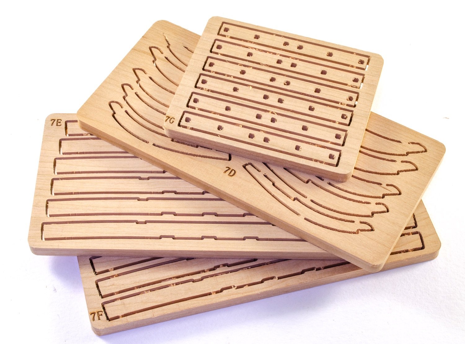
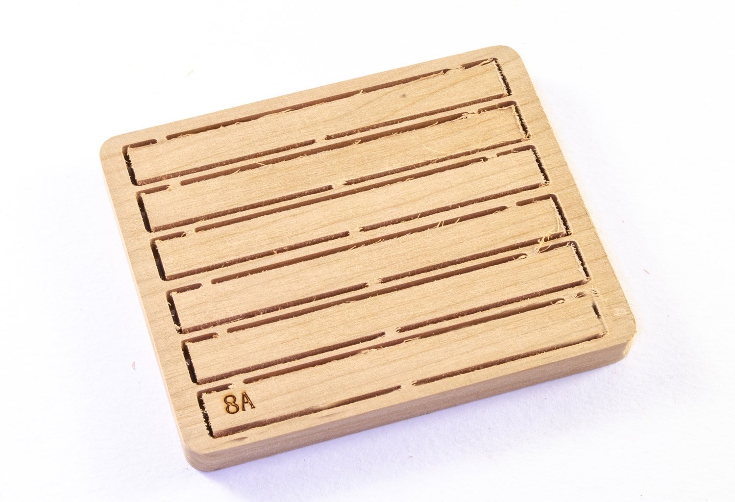
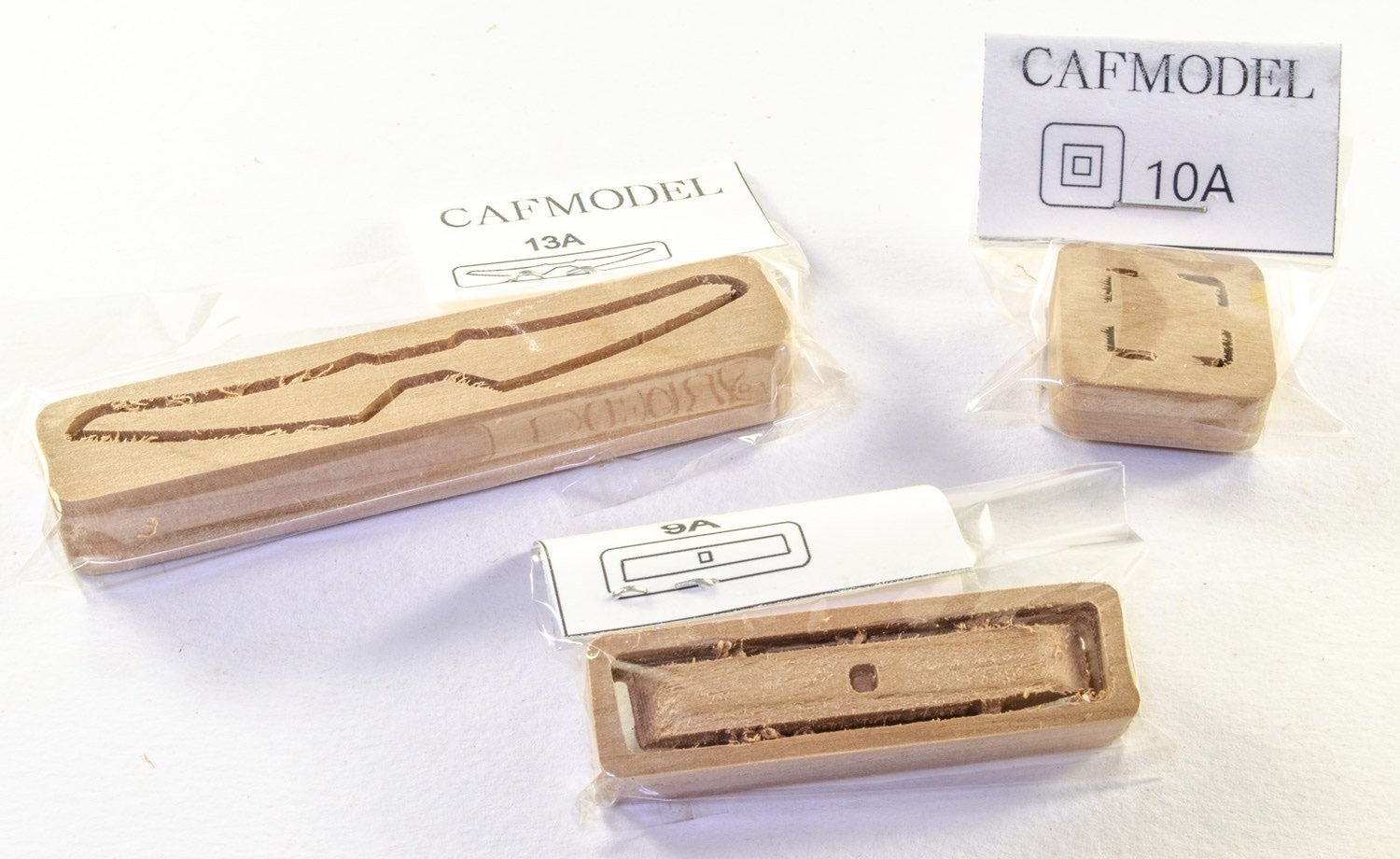
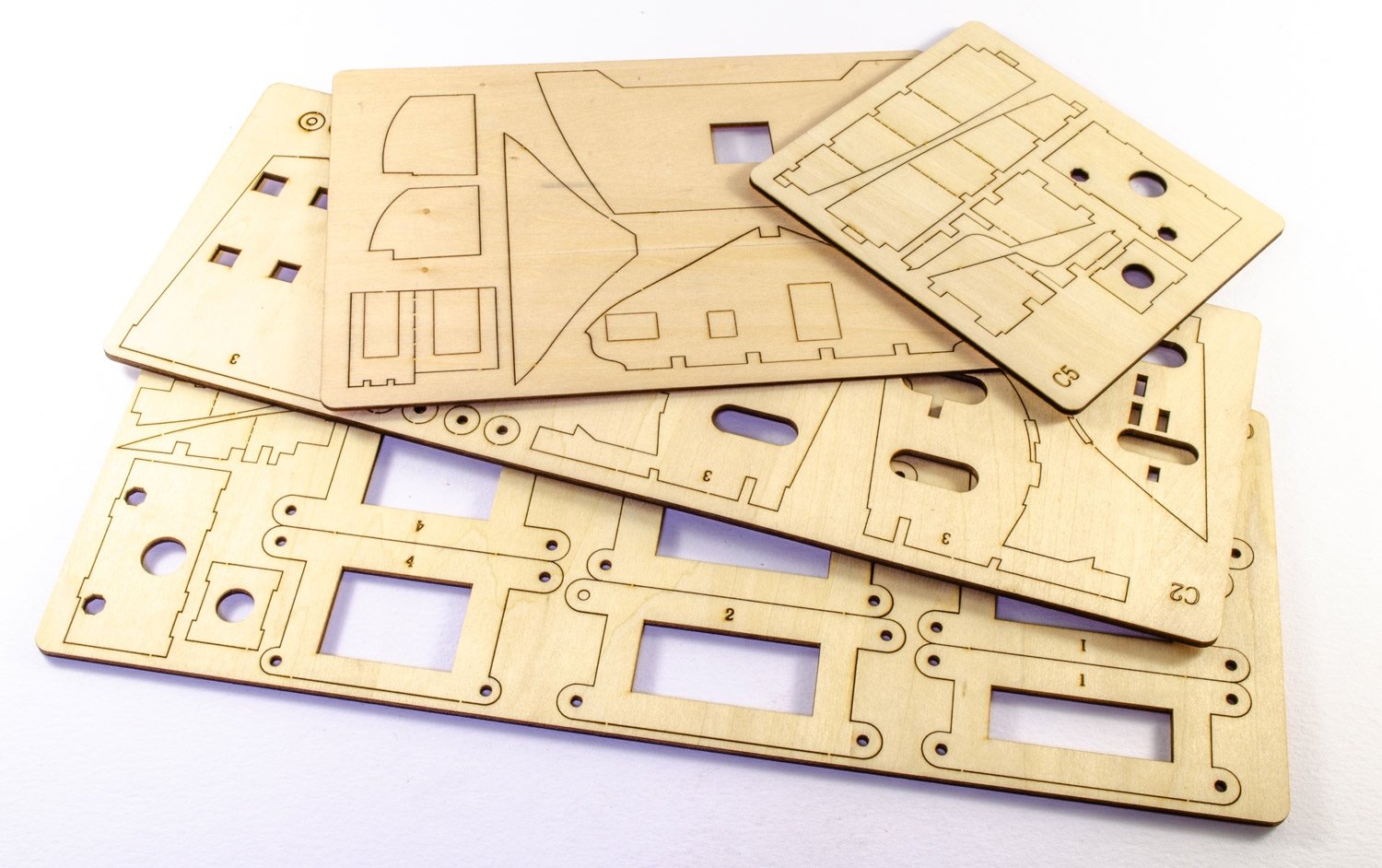
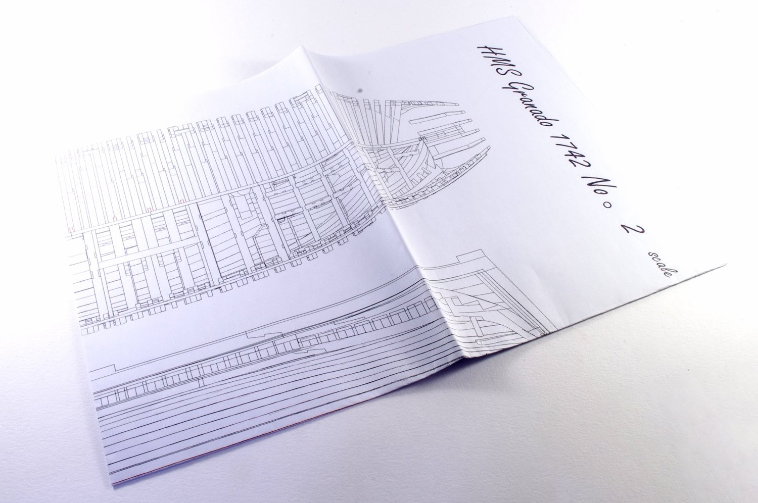
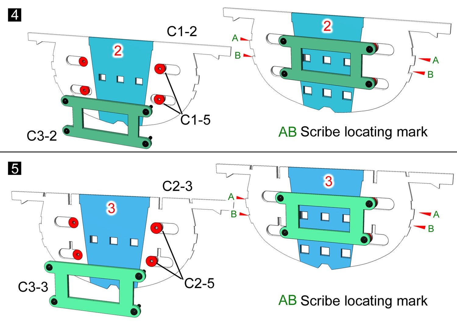
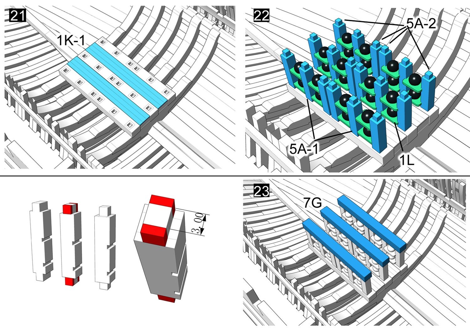
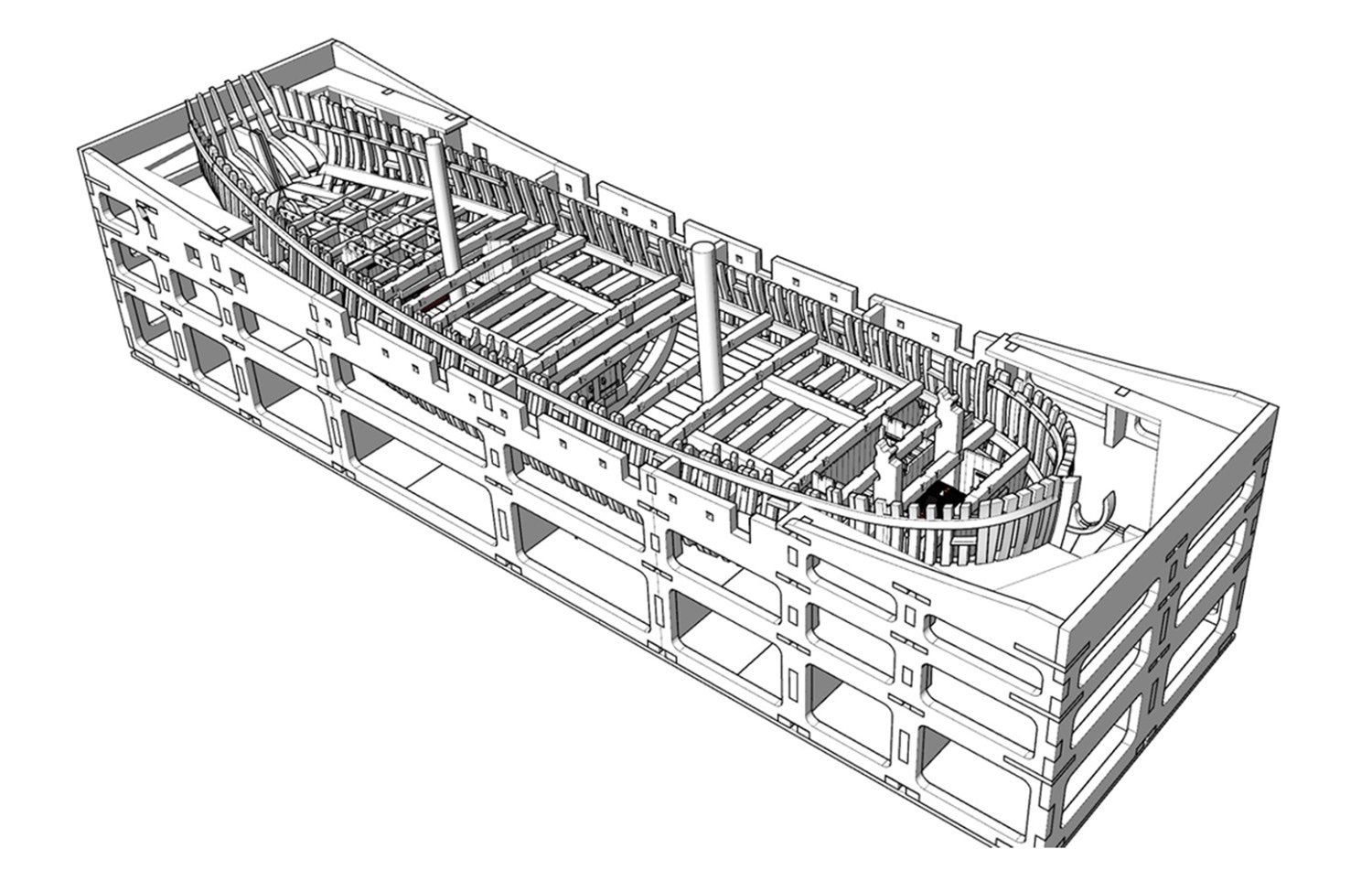
1:48 HMS Granado CAF Model Available from CAF Model. Check article for pack prices Lieutenant Thomas Elliot commissioned Granado in July 1742 as a sloop for the Channel and North Sea. HMS Granado was launched at Harwich in 1742, during the War of the Austrian Succession as a sloop-of-war. During this war she captured a French privateer. During the Seven Years' War she served both as a sloop and as a bomb vessel and participated in naval operations off the coast of France and in the West Indies. Granado was paid off in June 1763. She was surveyed on 6 July. The "Principal Officers and Commissioners of His Majesty's Navy" first offered Granado for sale at Woolwich on 23 August. She sold on 30 August at Portsmouth for £575.When the Navy sold her in 1763, she became the mercantile Prince Frederick. Around 1775 she became the northern fisheries whaler, Prudence. Around 1781 she became a government transport and was wrecked on 20 May 1782 on the coast of India. The kit: CAF have currently released their 1:48 HMS Granado (full hull kit) in two packs, and this first part of the review will look at Pack #1, comprising of TWO boxes of parts. The price for Pack #1 is $327.00USD, as is Pack 2 which consists of a single box. I'll look at that set in the second half of this article. There will be a Pack #3 released in the near future, which will fit this model out to the status of an Admiralty model, with guns on deck and all the various other features we would expect to see, such as the mortars themselves. HMS Granado Pack #1 Pack # contains everything you need to build the keel and hull framing for this famous bomb vessel. That means there is no interior at this stage, but don't think that you won't get a whole lot of timber. With all the boxes in this kit, once those parts are removed from their boxes, I simply find that I can't get them to fit back in again. When CAF originally sent this kit to us for review, a number of parts sheets had particularly bad scorch marks on the reverse. I highlighted this to Tom, and he was aware of the issue with a number of those that had shipped to customers, and he quickly replaced those and sent them out for this article. I also have to say that HMS Granado took about a week to reach the UK, from China. As with everything from CAF, the shipping package is totally robust, wrapped in thick corrugated card and sealed with about 1000 miles of tape! That would present a delicious headache for any custom's department! Nonetheless, it arrived intact. What you get in this pack will create the CAD image you see above. Oh, and of course, you also receive a large plywood jig into which you will add the many frames to your keel, once built. Remember, this model will not feature a bowsprit when complete, as is the nature of such models, so even though this is 1:48, you may be pleased to know that the full-length if Granado is actually only 670mm! Plus you don't have masts and spars to worry about. For displaying, she'll be far easier than most model ships. There is actually something else for you to consider with this model. You can either build her as a complete hull, or you can build her split into an upper and lower section, exactly like the well-known model at the UK's National Maritime Museum. Here you see what I mean: The plans make provision for all frames and keel to be split at the appropriate places, and you will see this in the instruction images further on in this article. I do feel that to do this presents some serious challenges and that is on top of this model only being suitable for very experienced builders. BUT.....if you want that challenge, then it's there for you. Inside the boxes, all parts are amazingly well packaged so that they fit the box, and they are also all shrink wrapped. As the shrink wrap is nice and tight, it's worth keeping the parts in that for a while after you receive the model so that the timber can normalise and risk of any warp is reduced when you open the parts. All part sheets are engraved with the sheet number, and you must then refer to the manuals for the part identification. This helps keep the sheets compact and the numbers of visible part faces. Timber-wise, the kit is made up of both laser cut and engraved parts, plus a good number of CNC cut parts sheets which feature slot milling on both sides, so that all you need to do is square of any joint corners which will inevitably be slightly rounded. A small number of parts are also CNC machined to shape, so you just need to clean them up. We've seen this on such kits before, and it saves the modeller a lot of guesswork in trying to think in 3D. I did say these packs were full of timber, and they are also quite heavy. The timber varies only very slightly in colour on the occasional sheet, but the quality of the wood is excellent, with no natural problems with grain banding or knots to be seen anywhere. As I said, all sheets are also perfectly flat. I'm not quite sure what the timber is for these sheets, but the grain is very tight and not particularly visible, which is a bonus for modelling in the scales we use. The timber sheets in the first box are numbered as sets, i.e. 1A, 1B, 1C, 2A, 2B, 2C etc. and the sets are of different thicknesses. You can also see on the sheets, just how fine the laser cutting is, and one image showing the reverse of one sheet so you can see the minimal scorch. In fact, that sheet is probably the worst of them all, so it's not bad at all! Many parts sheets are also engraved with bevelling lines, taking a lot of the hard guess work out of things. You can also see from that last image that not only is that scorch on this (the worst sheet!) isn't very bad, but CAF has also turned the sheets over to create engraved bevelling lines on the reverse. Box Number 2 of 2 All parts in these boxes have already been unwrapped so I could ensure everything was ok to proceed with this article. This larger box contains the many plywood parts for the hull jog, providing an accurate way to install and align the ribs to the keel. The jig itself will also serve to work into Part #2 of the kit set, when you come to fit out the hull interior. Here is an idea of what the jig will look like when complete: Here are the pictures of the cradle parts: This is a project in its own right. Even though everything is tabbed, proceed nice and slowly and use a metal square to make sure everything is upright and 90 degrees to adjacent parts. Ply quality is also very good with no warping on my same, and all laser cutting being nice and fine. There are also more timber parts for hull construction, provided as CNC-routed parts. Also a little strip material too. Manual and plans The manual for this set is an A4 production of 26 pages, incorporating the aforementioned part maps for part ID. The construction side of the manual is created from a series of CAD illustrations, shown in colour for ease of use, and with some good English notation. The manual clearly shows how to proceed with building the model as a split hull too, but I think to try and make this a removable section is a little too optimistic due to all those frames needing to key into each other simultaneously. Here are some images from the manual: And as for the included drawings, these show the hull elevations as shown below, and also the completed frames. I won't show the latter as it could be used as a copy to produce parts without buying the kit. It does show various lines in different colours, to help you align and identify the various frame sections. To give you a general idea of how the hull in constructed within the jig, here are some images from CAF: I will very shortly post the next box series #2 in this topic.
_bomb_vessel_RMG_J0387.thumb.jpg.08e3195819f5eb0b1256be4cff8b5537.jpg)


-

How many kits do you have on the go at the moment?
James H replied to CaptnBirdseye's topic in Wood ship model kits
I have a delayed HMS Victory prototype by Amati, and I'm currently building Vanguard Models' Ranger fisher. Ranger will be done soon, then it's onto Indefatigable. There is a Mary Rose lurking in the background, and Panart's 'Posto di combattimento', but those are ancient projects now, so don't really count until I ever decide to resurrect them. MK's AVOS is also there, and that will be done as soon as time permits. -
Those look pretty. One reminds me of the WW1 dreadnoughts.
-
kit review 1:65 HMS Endeavour - Artesania Latina
James H replied to James H's topic in REVIEWS: Model kits
You know it makes sense 🤣 -
kit review 1:200 German Battleship Bismarck - Amati
James H replied to James H's topic in REVIEWS: Model kits
At the moment, my shipyard is rammed with stuff I either need to do, or will soon need to do. Bismarck could be several years away yet 😂 -
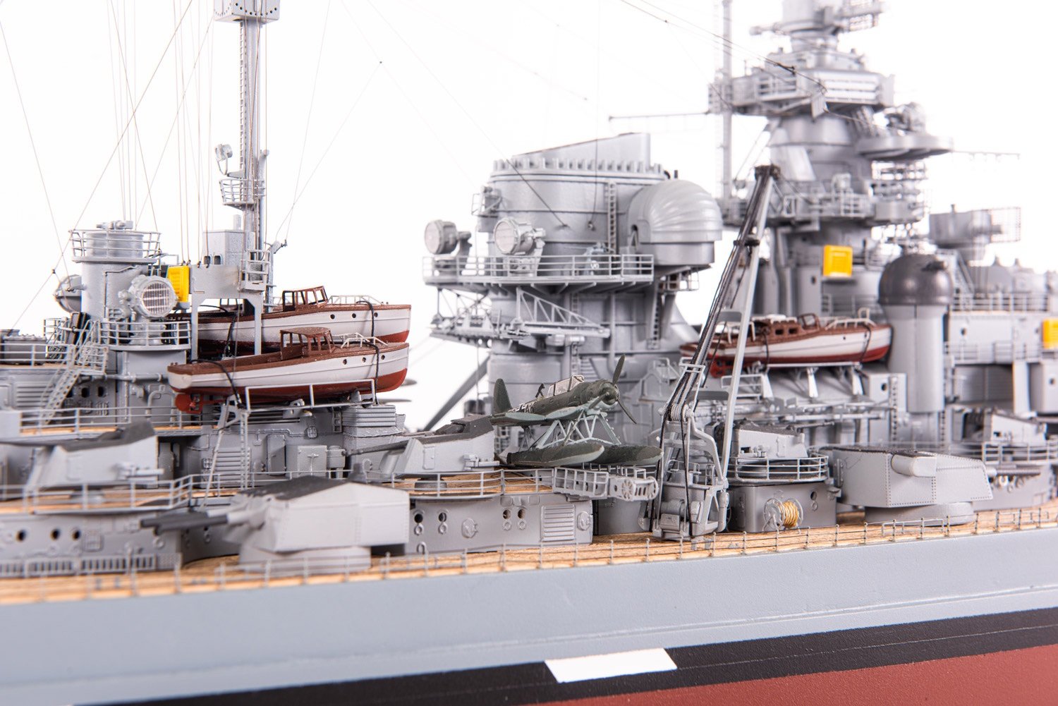
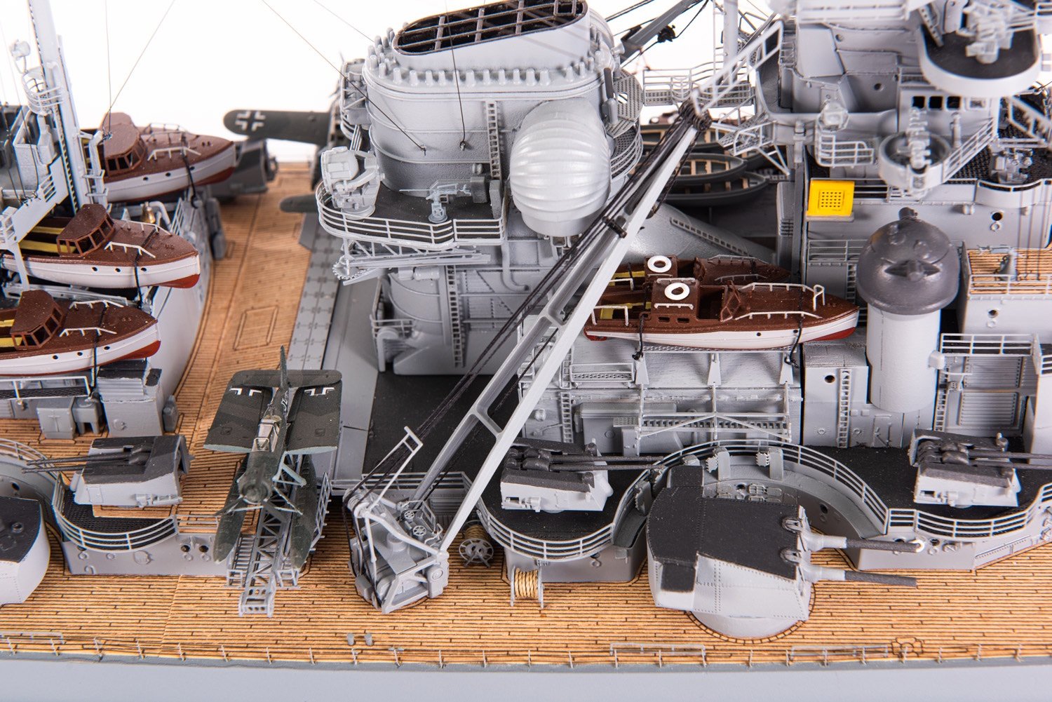
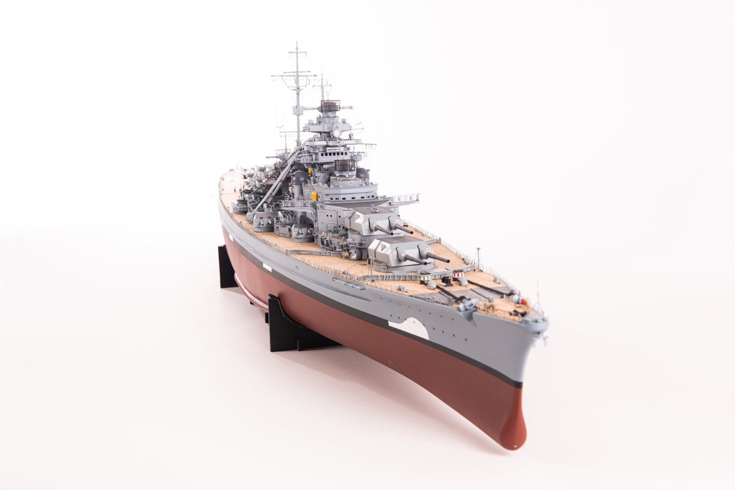
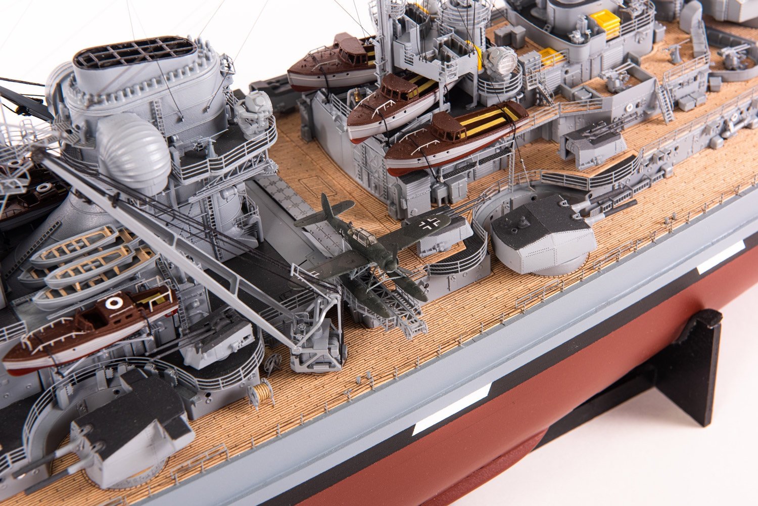
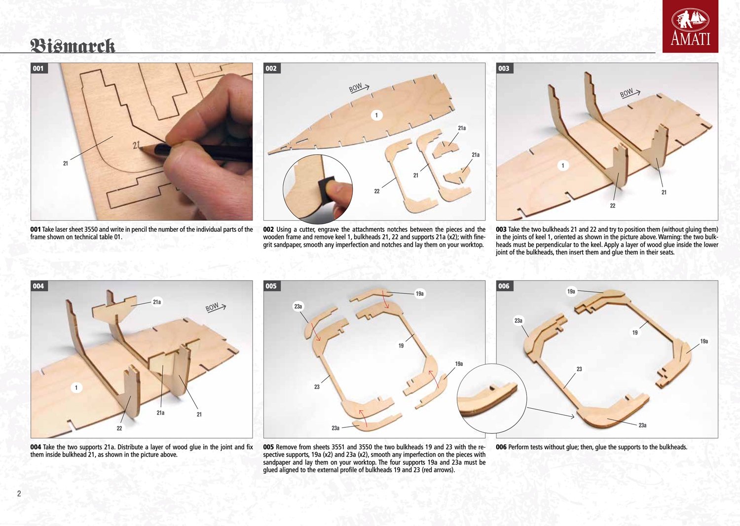
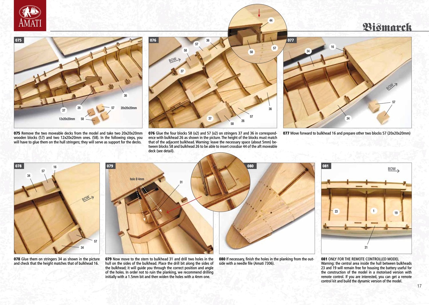
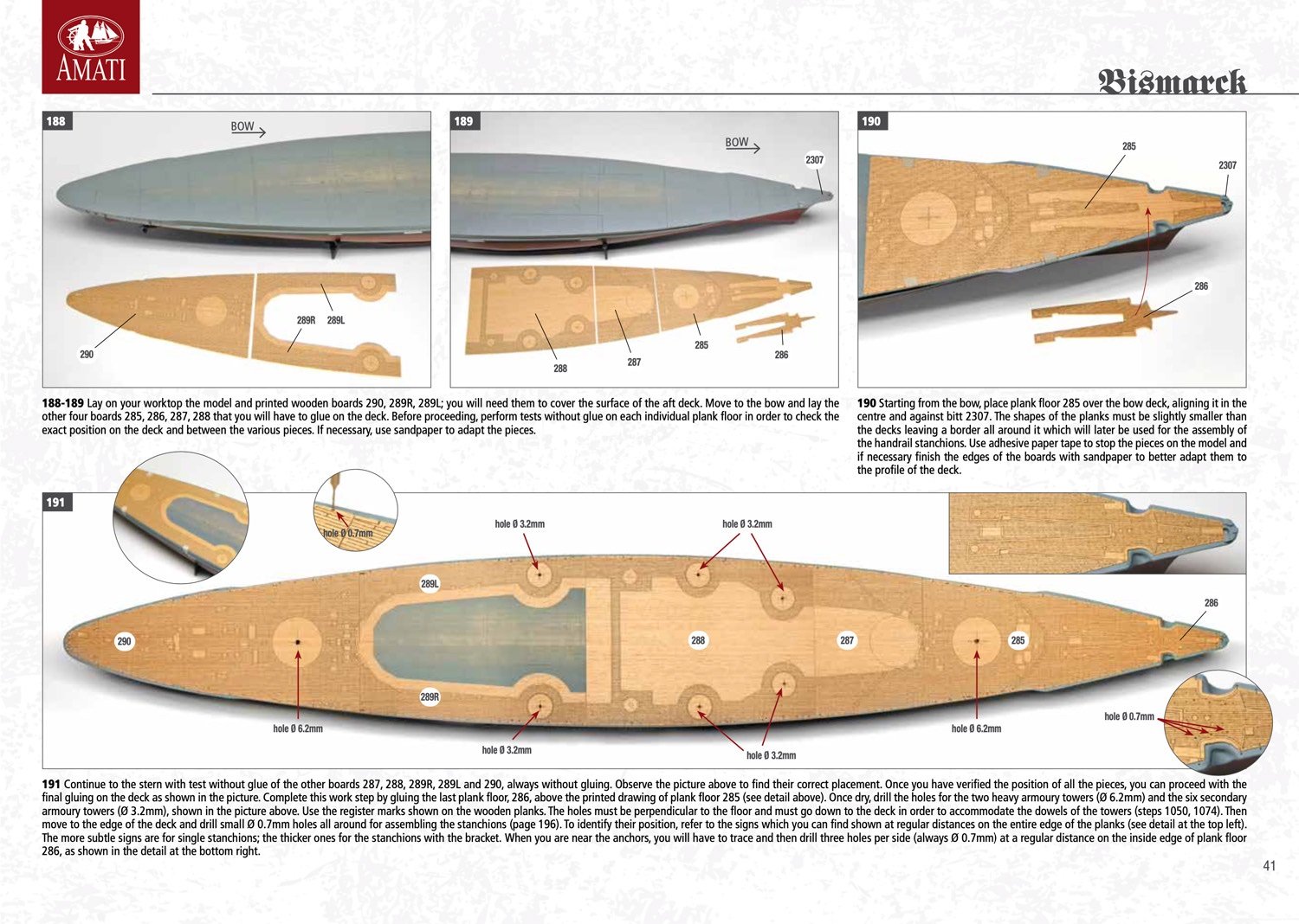
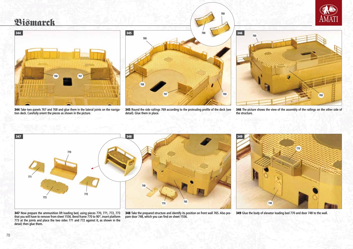
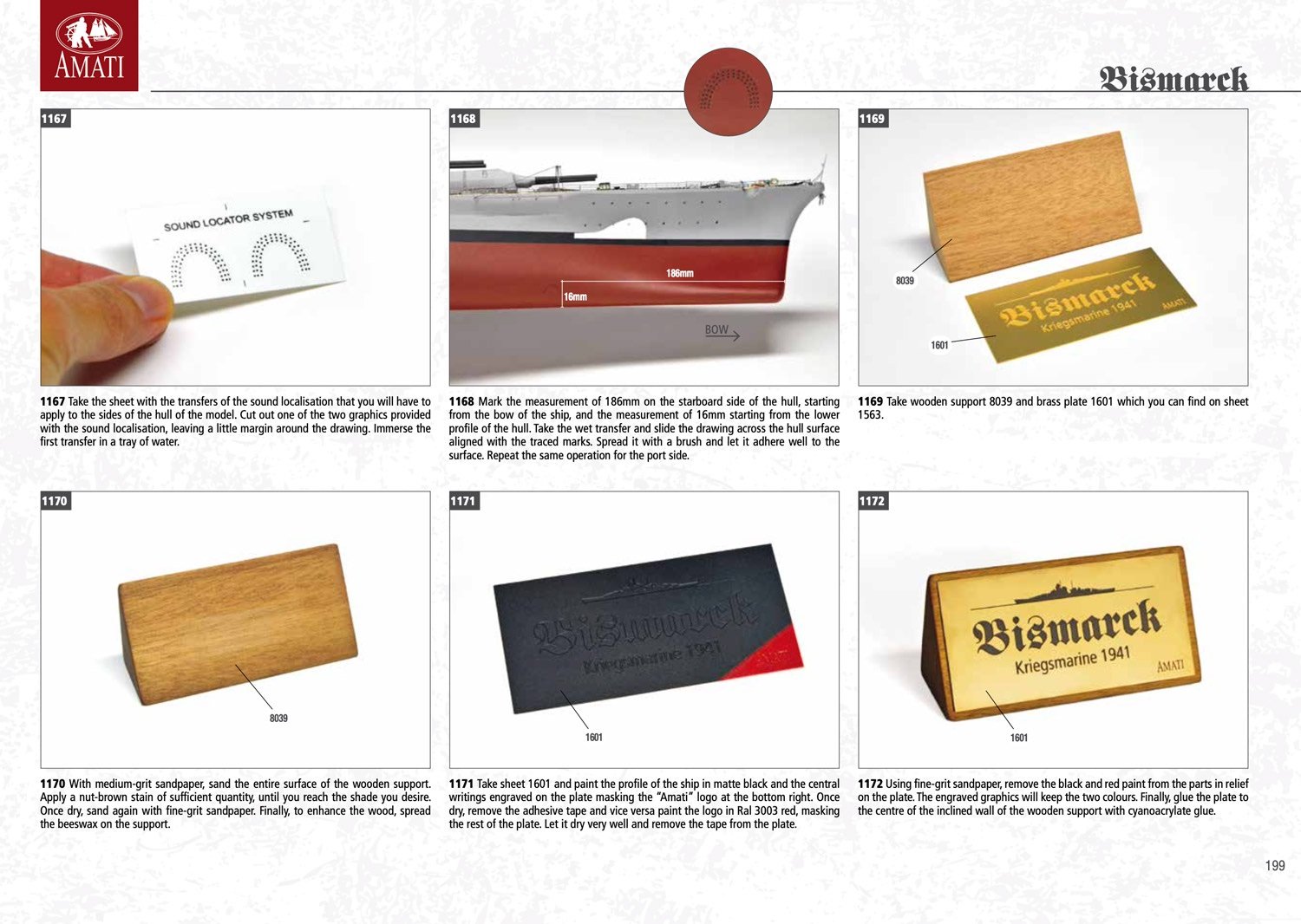
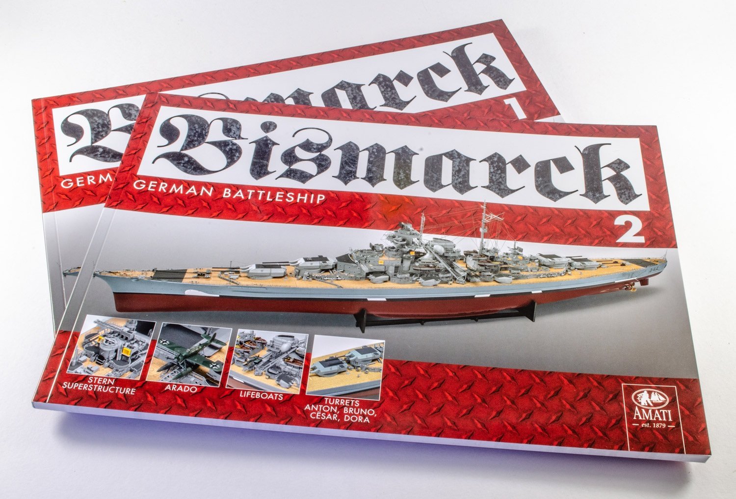
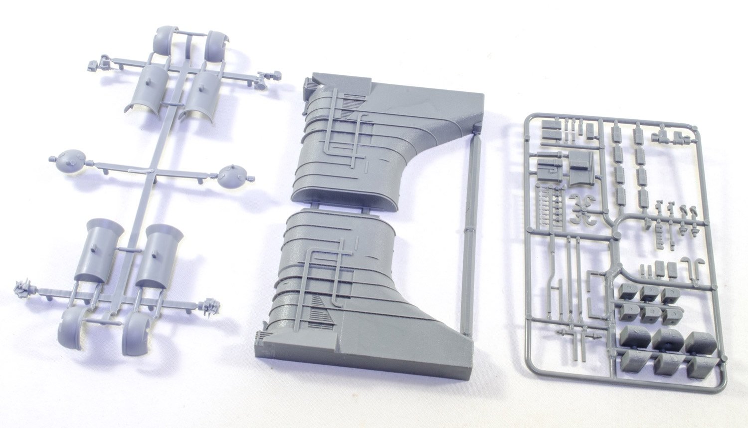
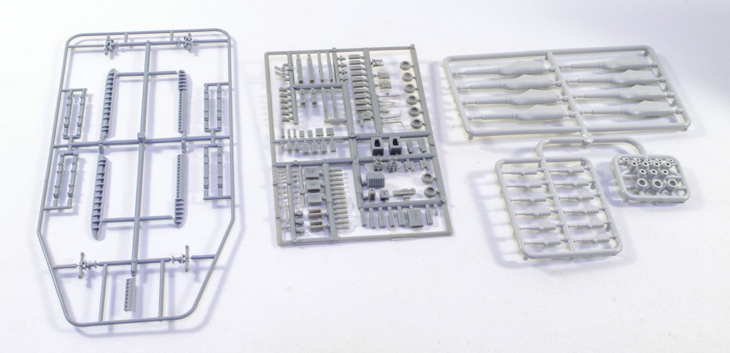
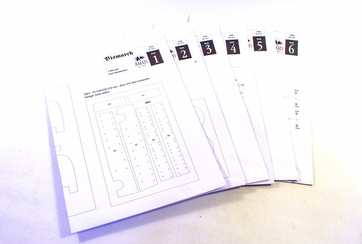
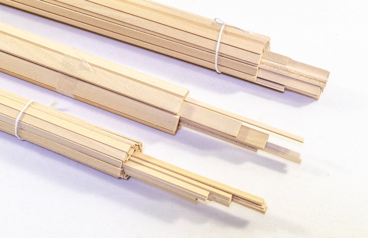
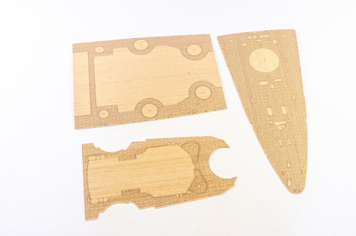
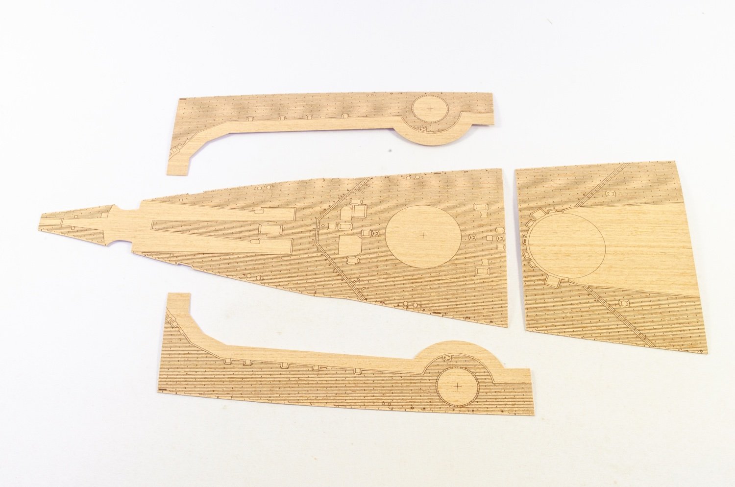
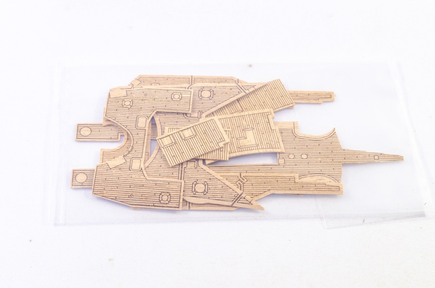
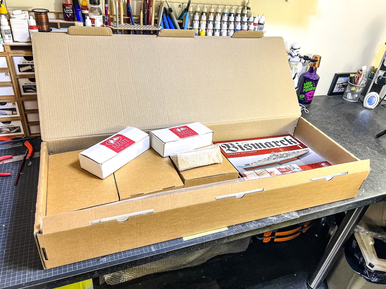
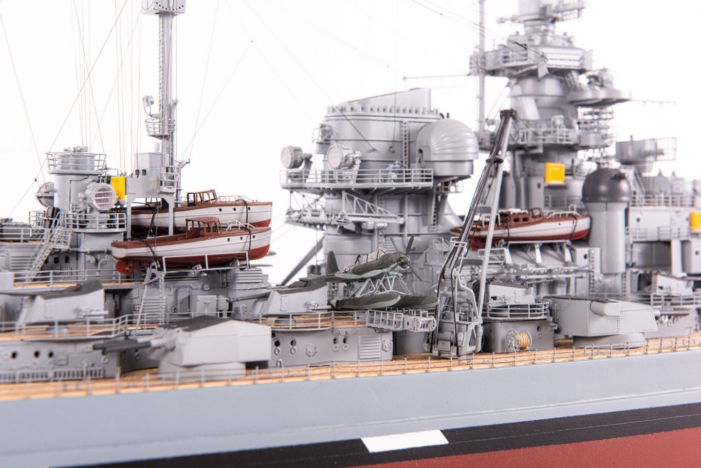
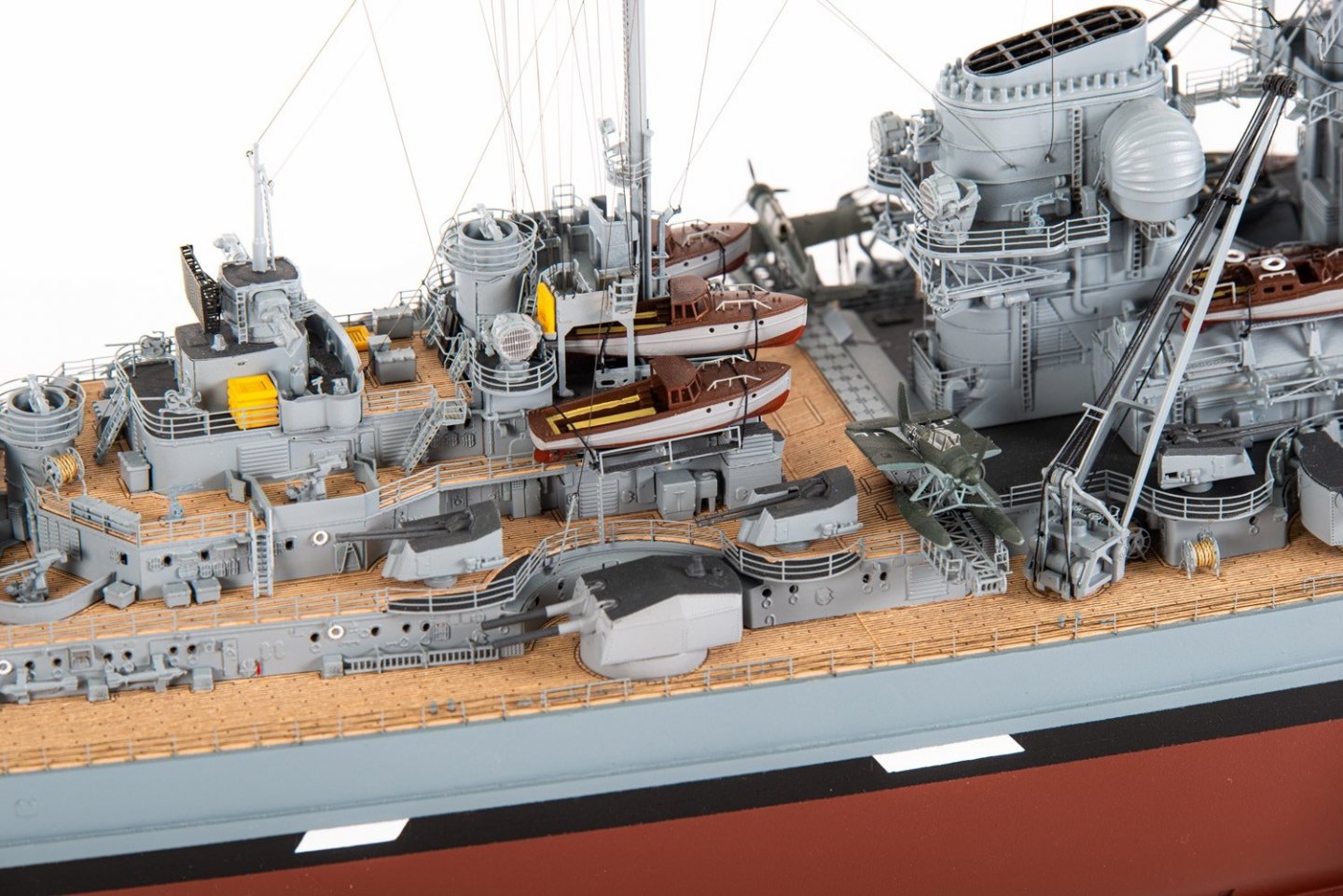
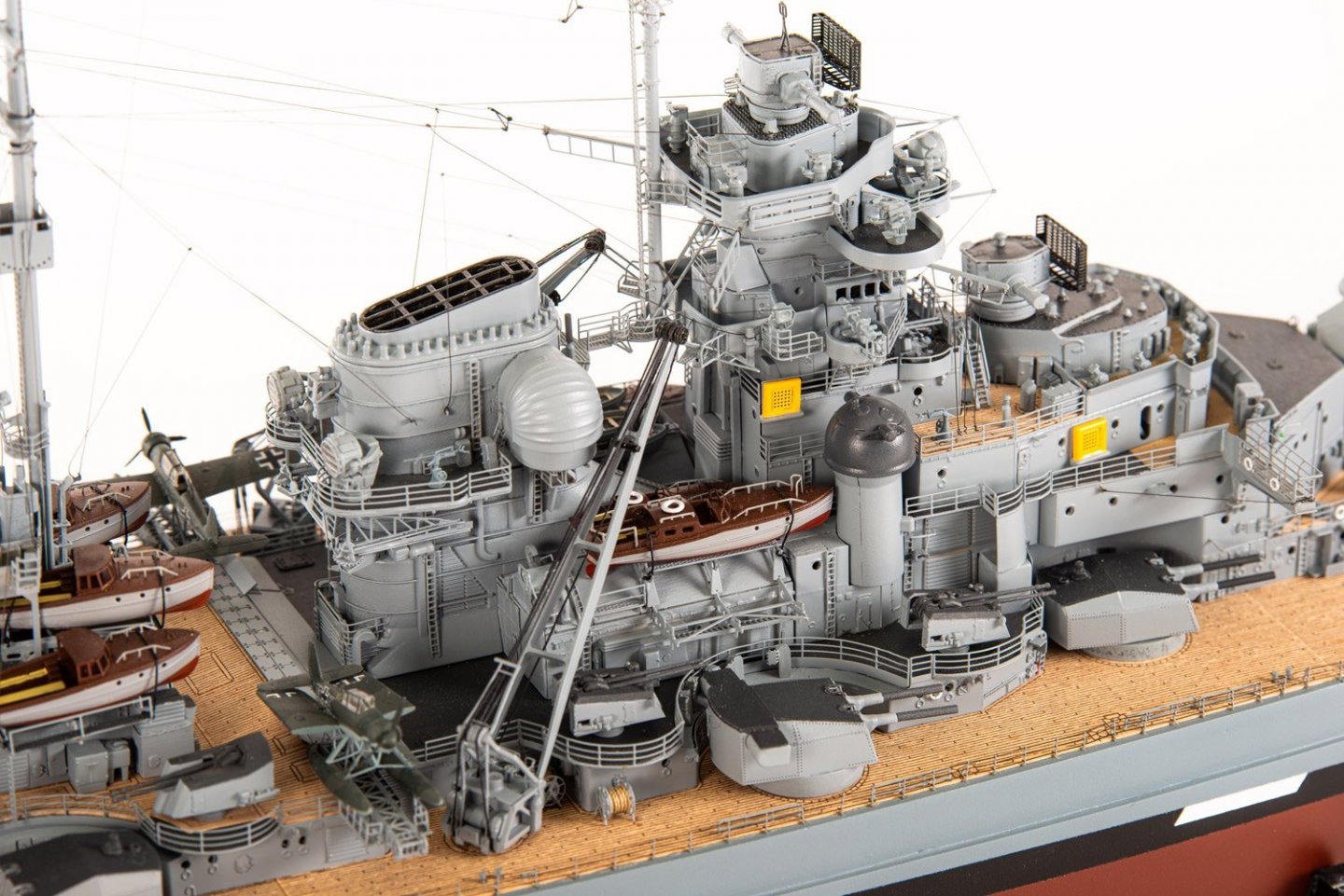
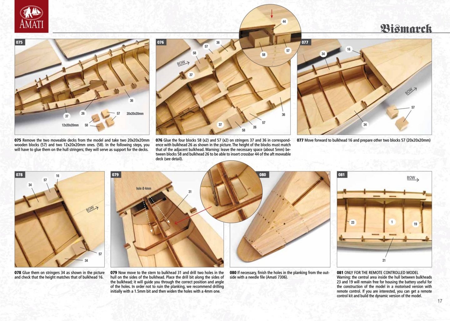
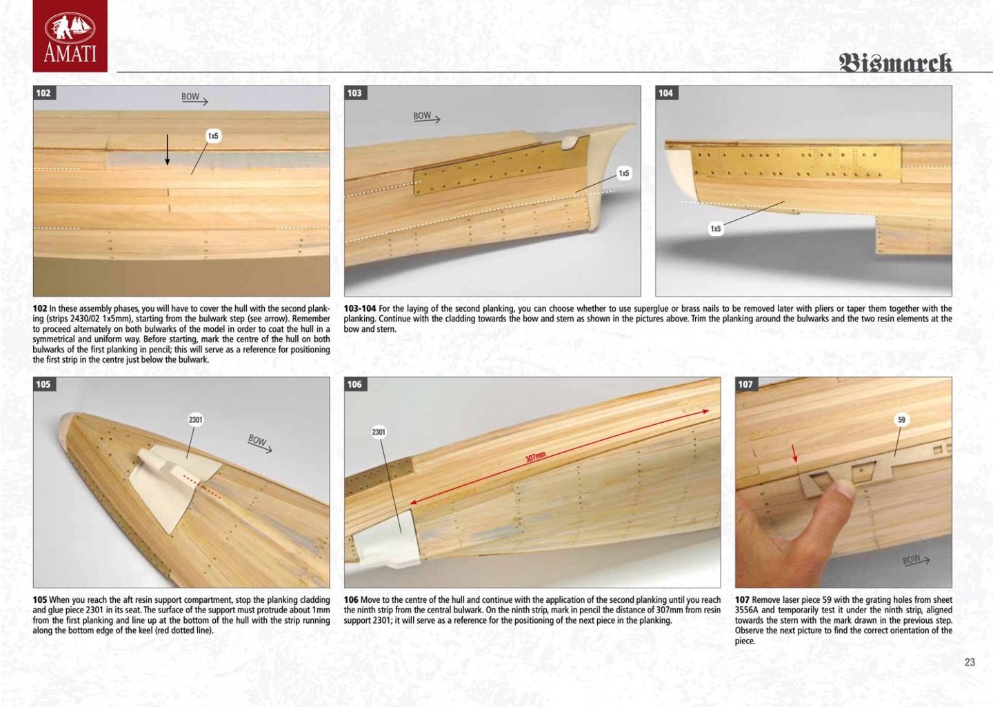
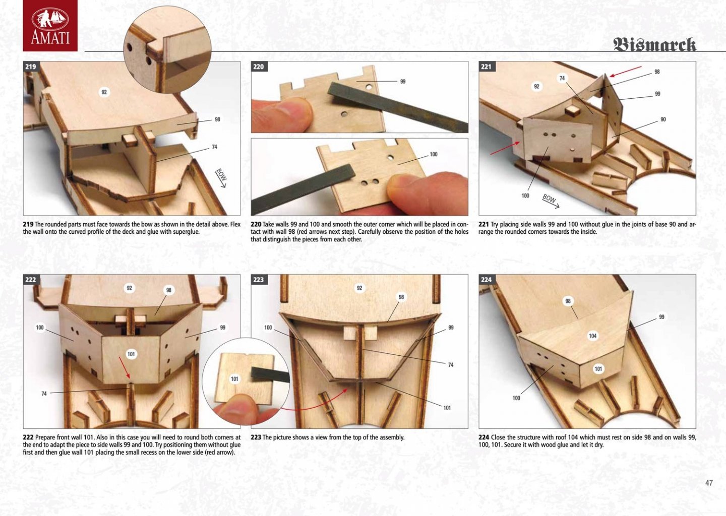
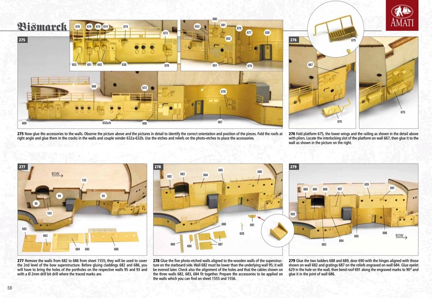
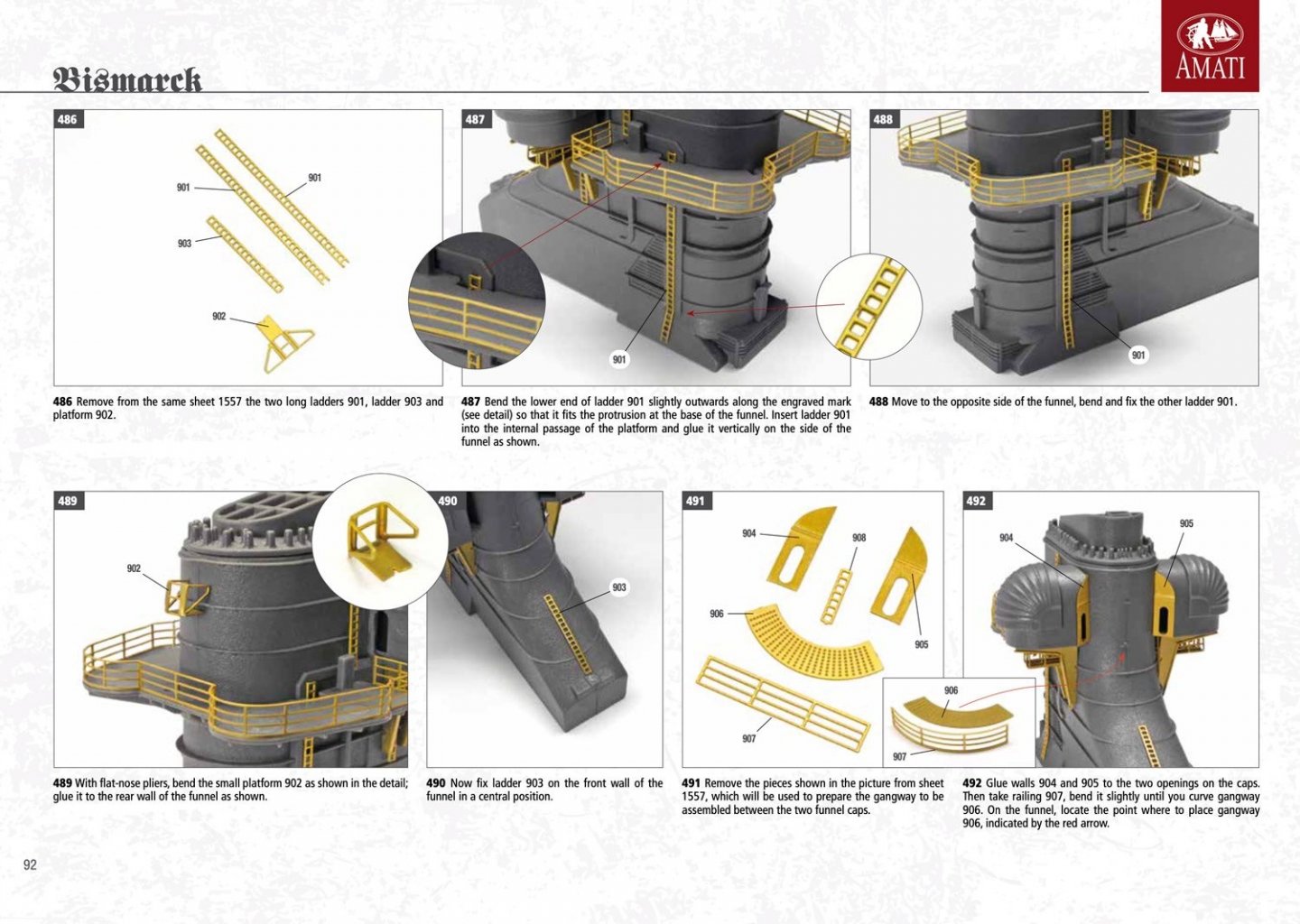
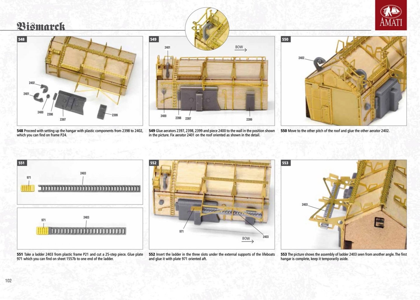
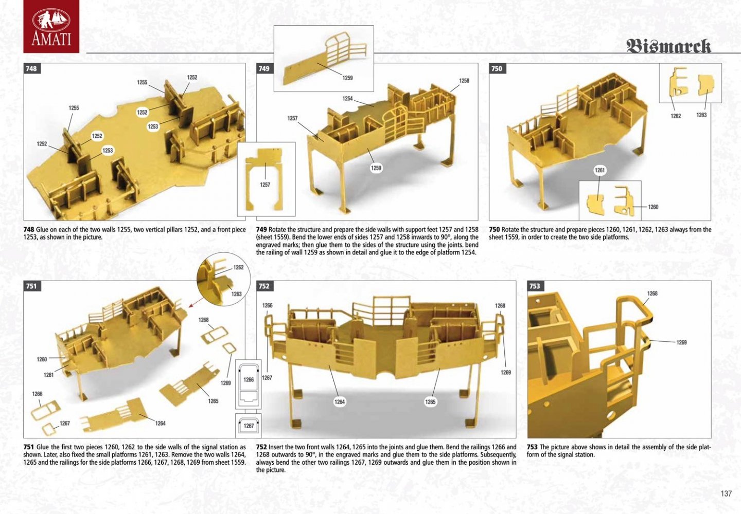
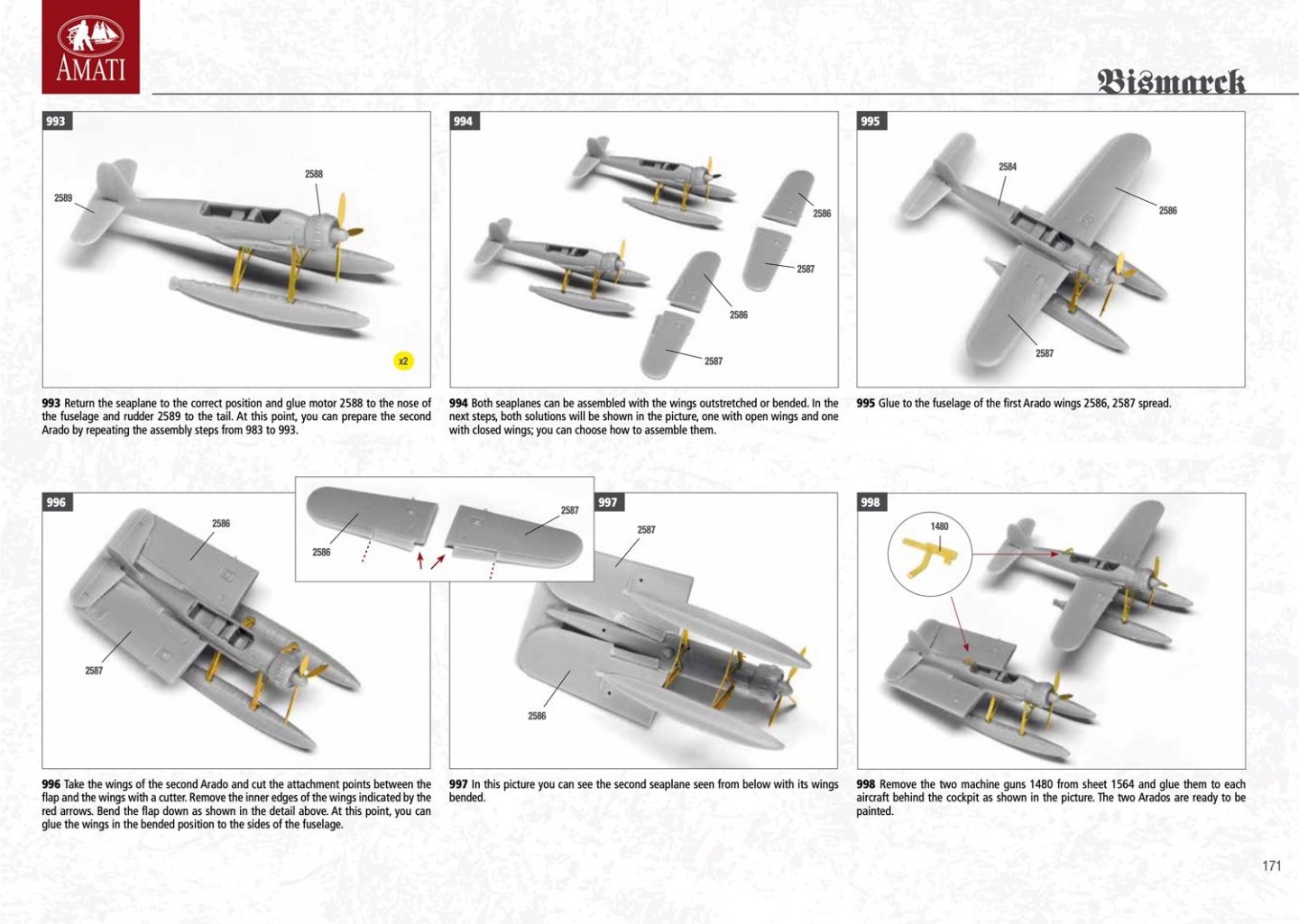
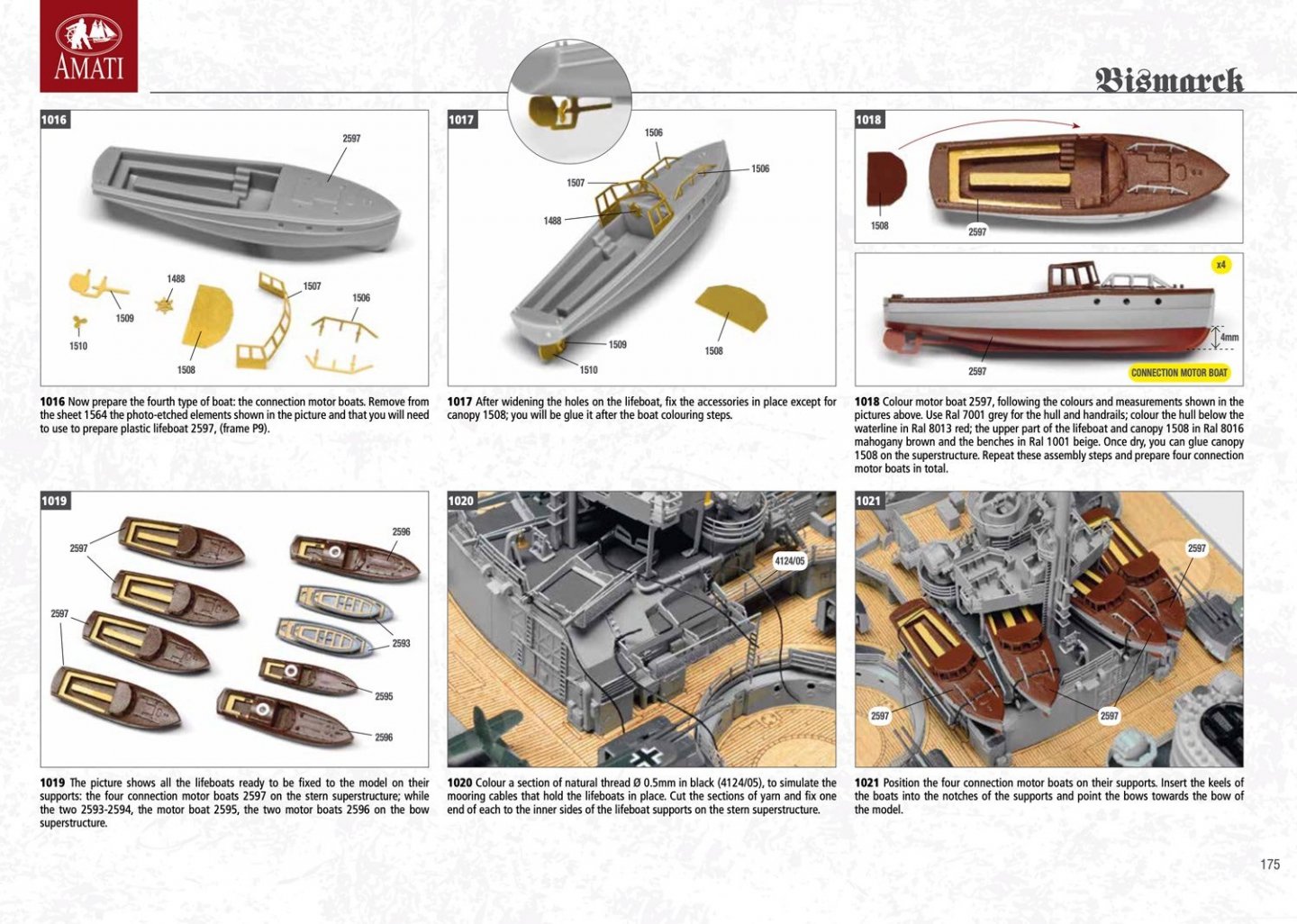
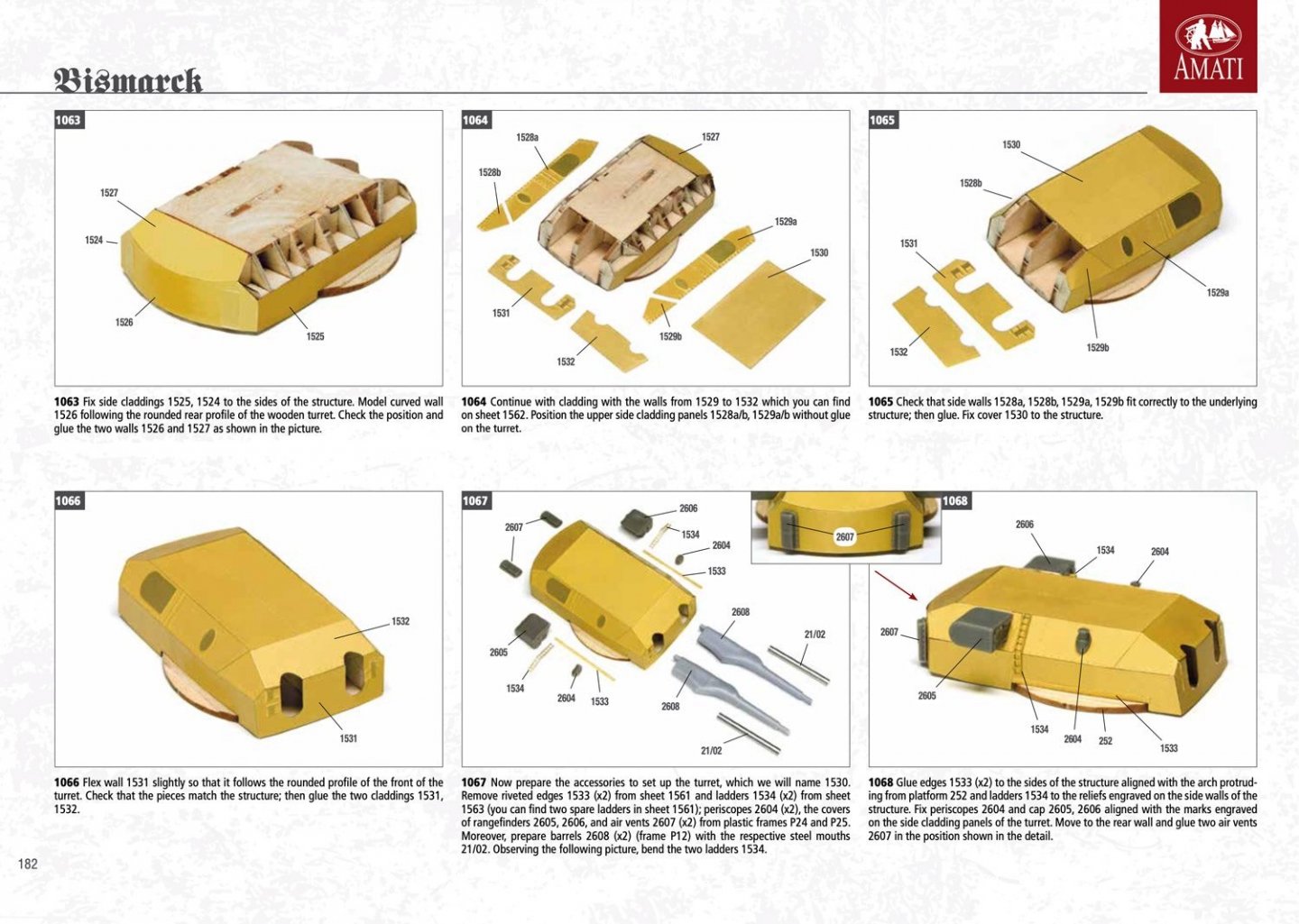
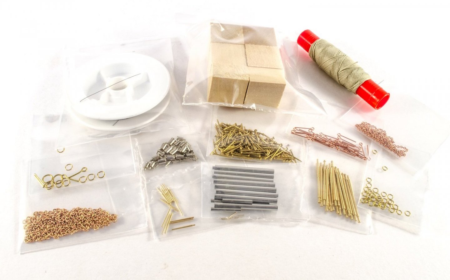
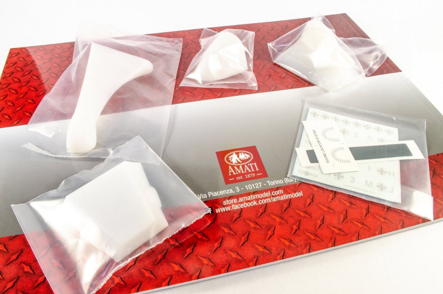
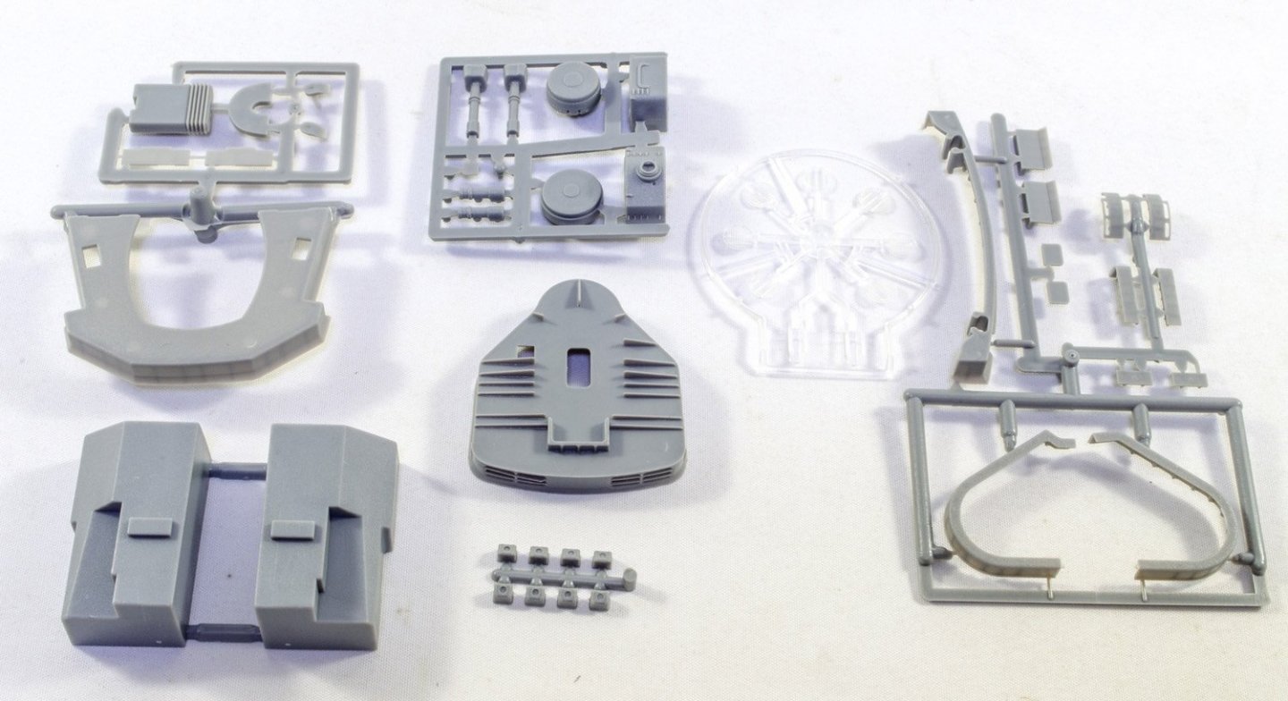
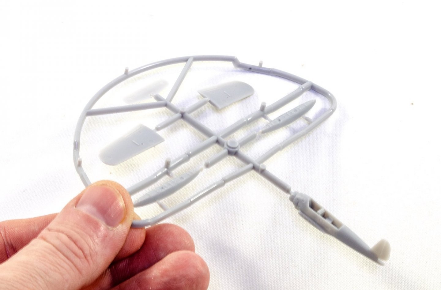
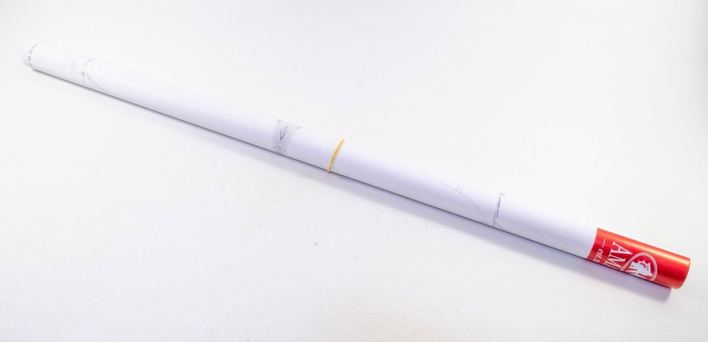
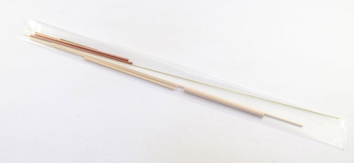
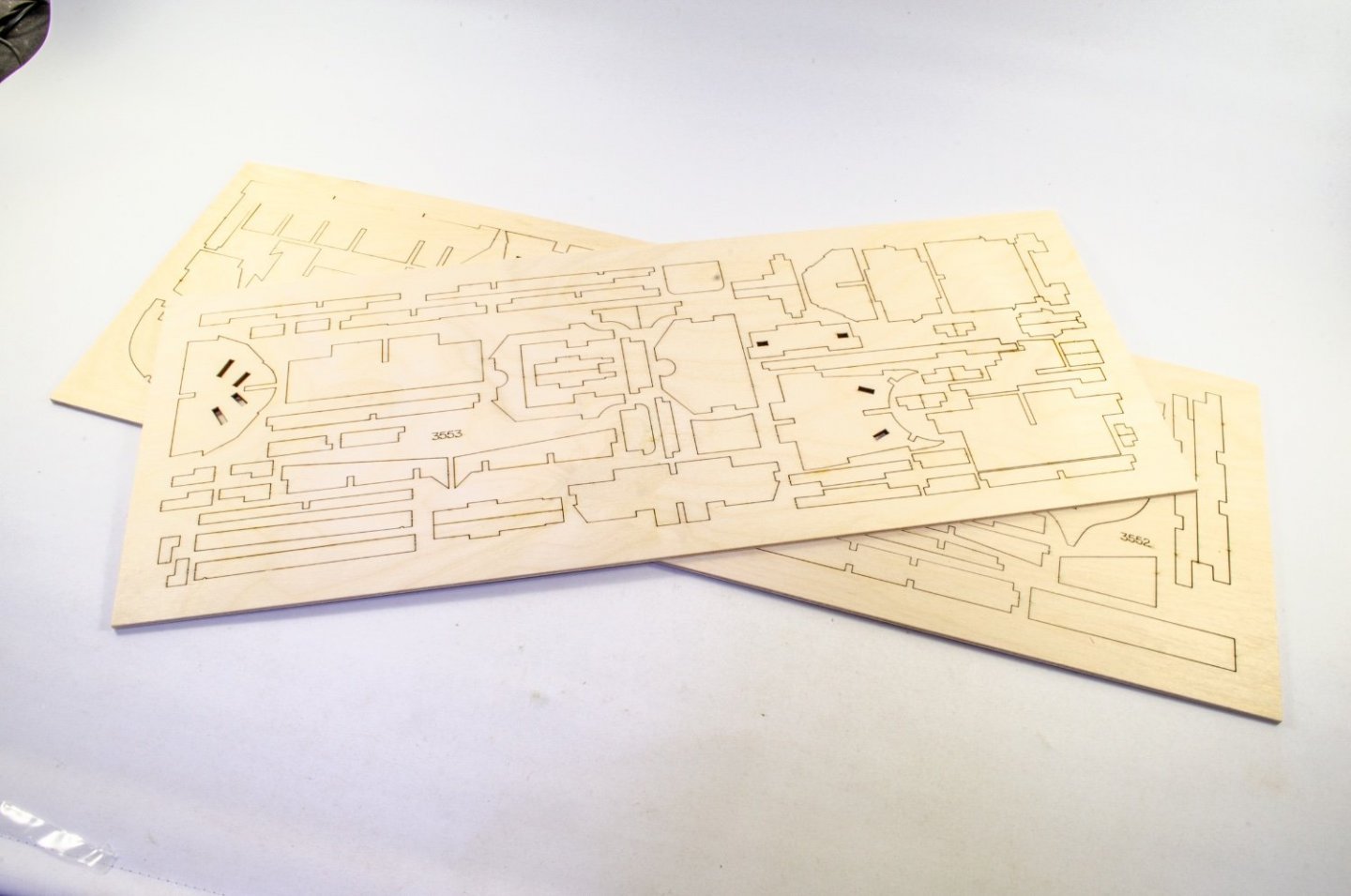
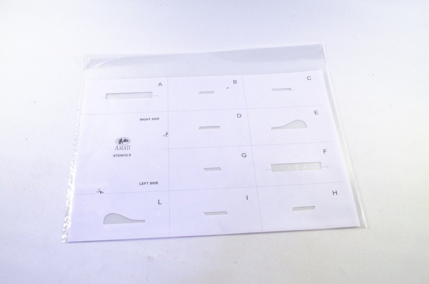
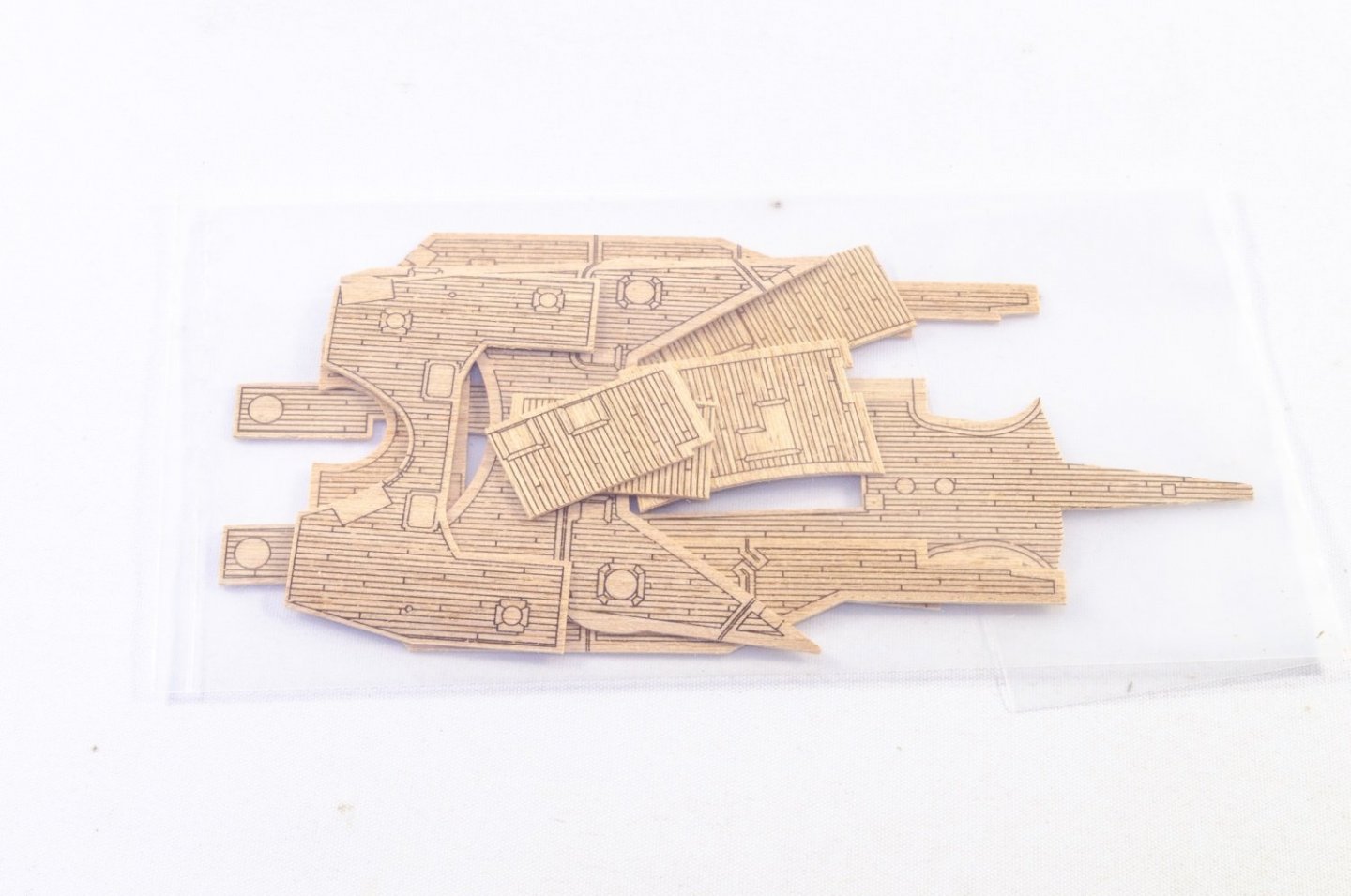
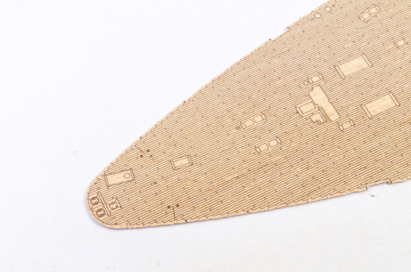
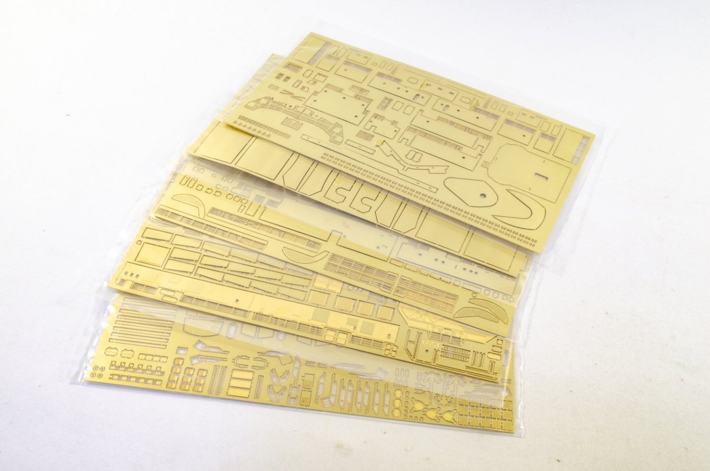
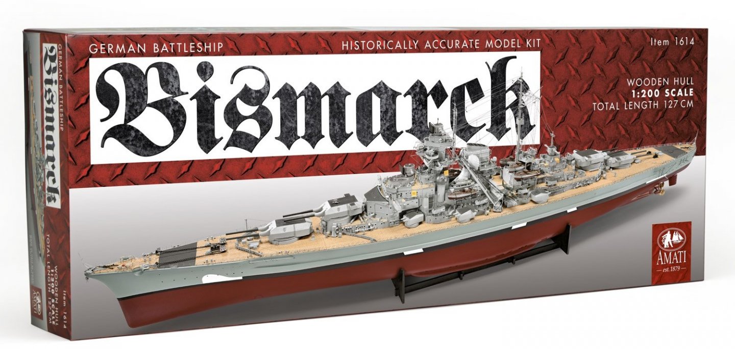
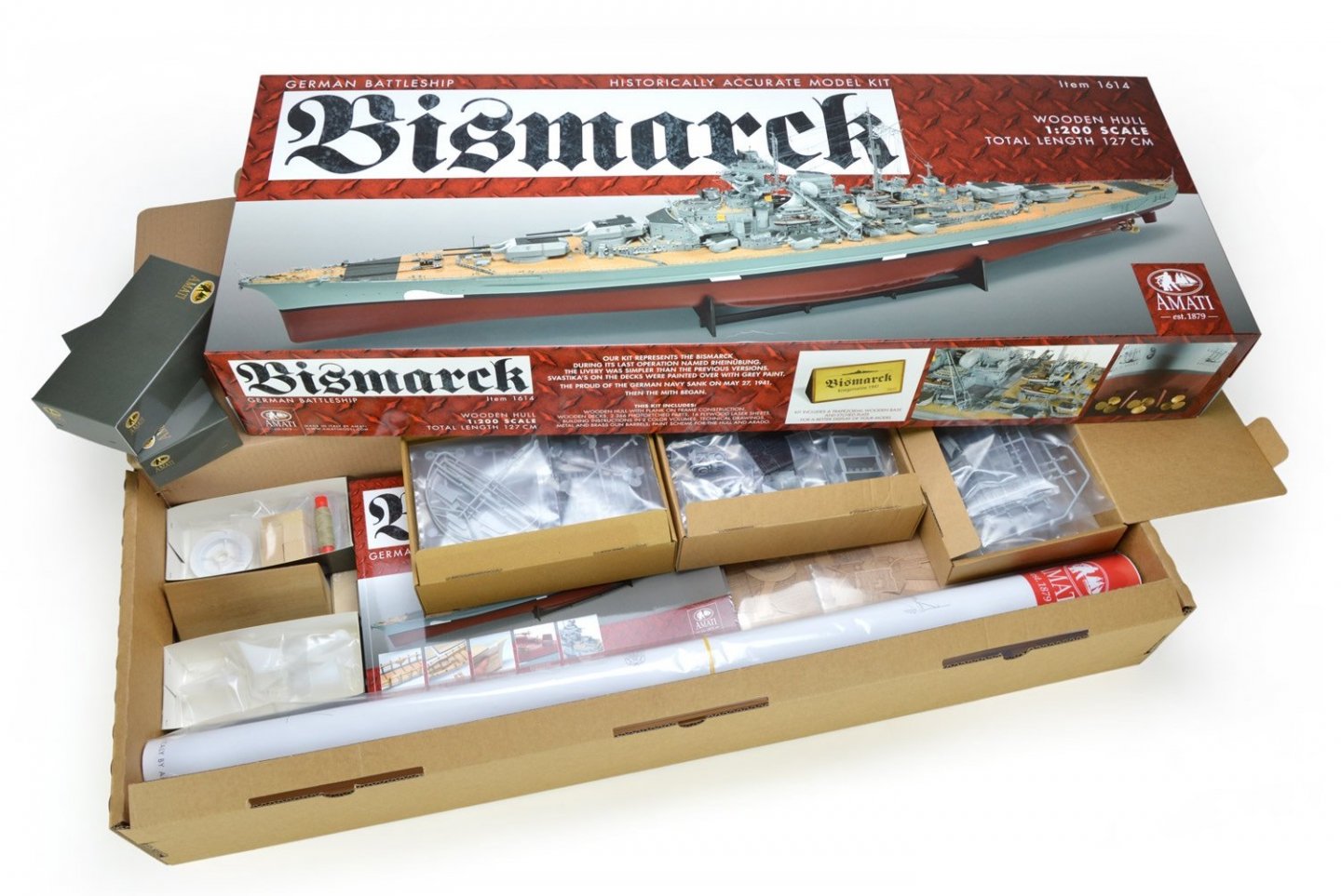
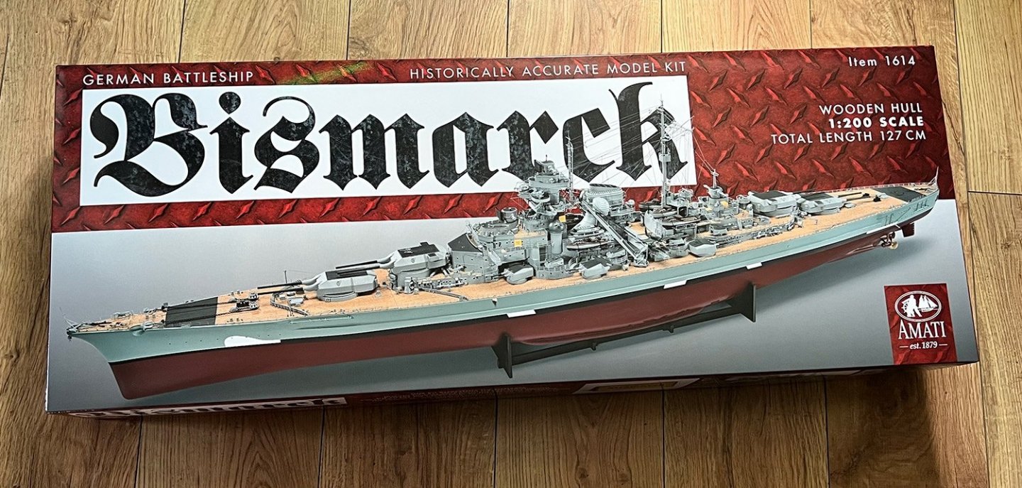
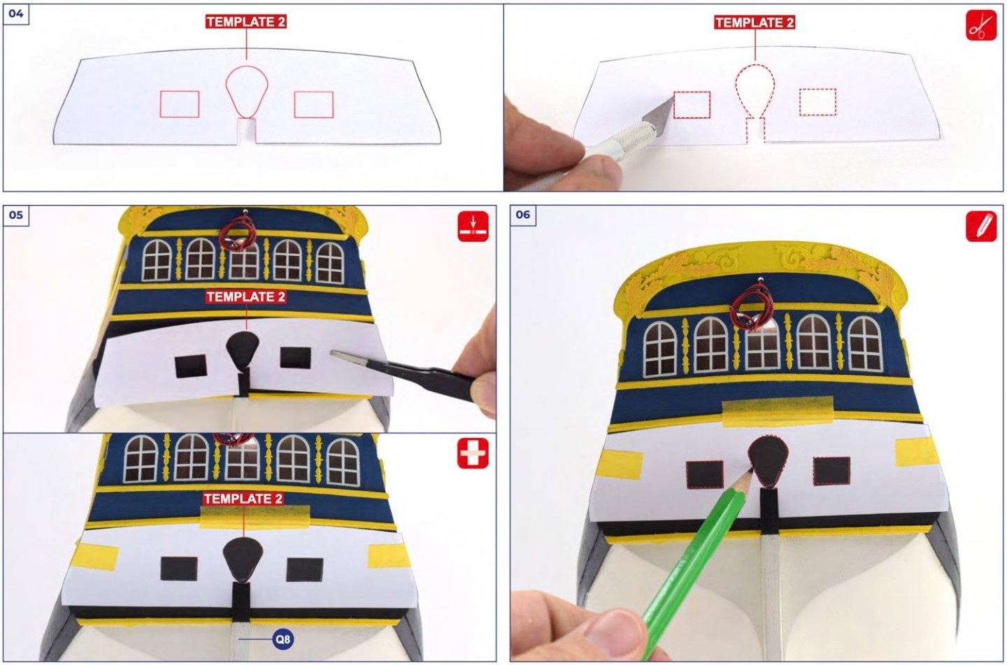
1:200 German Battleship Bismarck Amati Catalogue # 1614 Available from Amati for €499.51 History Bismarck was the first of two Bismarck-class battleships built for Nazi Germany's Kriegsmarine. Named after Chancellor Otto von Bismarck, the ship was laid down at the Blohm & Voss shipyard in Hamburg in July 1936 and launched in February 1939. Work was completed in August 1940, when she was commissioned into the German fleet. Bismarck and her sister ship Tirpitz were the largest battleships ever built by Germany, and two of the largest built by any European power. In the course of the warship's eight-month career under her sole commanding officer, Captain Ernst Lindemann, Bismarck conducted only one offensive operation, lasting 8 days in May 1941, codenamed Rheinübung. The ship, along with the heavy cruiser Prinz Eugen, was to break into the Atlantic Ocean and raid Allied shipping from North America to Great Britain. The two ships were detected several times off Scandinavia, and British naval units were deployed to block their route. At the Battle of the Denmark Strait, the battlecruiser HMS Hood initially engaged Prinz Eugen, probably by mistake, while HMS Prince of Wales engaged Bismarck. In the ensuing battle Hood was destroyed by the combined fire of Bismarck and Prinz Eugen, which then damaged Prince of Wales and forced her retreat. Bismarck suffered sufficient damage from three hits by Prince of Wales to force an end to the raiding mission. The destruction of Hood spurred a relentless pursuit by the Royal Navy involving dozens of warships. Two days later, heading for occupied France to effect repairs, Bismarck was attacked by 16 Fairey Swordfish biplane torpedo bombers from the aircraft carrier HMS Ark Royal; one scored a hit that rendered the battleship's steering gear inoperable. In her final battle the following morning, the already-crippled Bismarck was engaged by two British battleships and two heavy cruisers and sustained incapacitating damage and heavy loss of life. The ship was scuttled to prevent her being boarded by the British, and to allow the ship to be abandoned so as to limit further casualties. Most experts agree that the battle damage would have caused her to sink eventually. The wreck was located in June 1989 by Robert Ballard and has since been further surveyed by several other expeditions. A detailed underwater survey of the wreck in 2002 showed that the sustained close-range shelling was largely ineffective in the effort to sink the ship, the many torpedoes launched at Bismarck were also almost completely ineffective, and the plating of the armour deck was also found to be virtually intact. The kit There are other 1:200 Bismarck kits on the market, and Amati themselves worked with Hachette a number of years ago on a 2007 partwork release of this ship. This was subsequently re-released by DeAgostini but is now unavailable. Last year, Amati revisited the Bismarck themselves and released a reworked kit, which from what I believe, is a more accurate and certainly more detailed kit. I know Amati went to great pains to get this right and used numerous contemporary sources for their information. In this release, Bismarck is depicted in her final incarnation with her fore and aft deck swastikas painted over, and the superstructure disruptive camouflage obliterated. The only remnants of this are on the upper hull sides. As far as model ships go, this one is huge! In fact, the completed length is 127cm, so you will need some space to display her. Unlike a sail ship with her tail masts and broad yards, Bismarck doesn’t have the additional height and weight to encumber her. A large model will also come in a large box, and that’s definitely the case with this one. Bismarck uses the same size box as the other large Amati releases, such as HMS Vanguard, HMS Revenge, Fifie, and the recent Orient Express Sleeping Car kit. As a guide to weight, the packing carton did give the figure of 10kg (22lbs), so that’s a reasonable figure to use. The box work for Bismarck is quite striking and depicts some views of the finished model. I have included these and other images of the finished studio model in this article. There are a couple of typos on the box side, but Amati are aware and will correct this in the next print run. The glossy lid itself is just a box cover, as when this is removed, the actual kit box is a complete one with a tabbed lid, making the whole thing very sturdy. Bismarck is based around a traditionally planked hull, on a very conventional timber framework. Where Bismarck’s hull may cause some consternation with planking, 3D parts are included which the modeller needs to blend into a finally sanded and shaped hull. Surface preparation will be one of the most important things when it comes to building this model, as you won’t want any planking strakes to be seen when painted. The whole hull will need sanding, filling, re-sanding, re-filling, until you have a surface like glass. Sealing the hull could also help, as could using glass resin and thin glass cloth. That will very much depend on your level of experience. If you wanted to build this model for RC, then it’s also possible as the upper deck is purposely left to be removed, although that’s as far as it goes. Any internal changes will need to be done by the modeller, but I don’t think this would be too difficult. There are definitely a lot of materials packed into this box. SIXTEEEN sheets of timber parts FIFTEEN laser-engraved deck sections FOURTEEN sheets of photo-etched parts in various thicknesses TWO large bundles of almost 140 planks for first and second layers Pack of dowels and metal rod Numerous 3D parts for tricky hull areas Many injection moulded sprues with superstructure details Brass chains Decorative nameplate/wooden plinth TWO full colour manuals with over 1000 constructional stages SIX parts plan sheets for part maps Large plan sheet of actual ship Here’s a look at the kit contents. Three boxes of injection mouldings Two boxes of assorted fittings Timber sheets Timber and metal strip Photo Etch Laser engraved decks Wooden plinth for photo etch nameplate Instructions and plans Two full colour manuals are provided for this kit. The first manual alone is 112 pages (landscape format) and has a staggering 612 constructional stages! That does seem quite daunting, but the stages re broken down in such a way that many of these stages will relate to individual areas, such as a single superstructure part, for example, and show the additional parts a few at a time. The first manual will take the builder from the basic skeleton of Bismarck, all the way through to a completed hull with superstructures underway. Manual #2 is over 90 pages, with another 560 stages. The second manual also contains a comprehensive parts list which you really should get into the habit of checking through with any kit you buy, let alone an investment the size of Bismarck! Six folded parts maps are also included. These are just a paper facsimile of the timber elements in your kit, allowing the modeller to perhaps find things more easily instead of manhandling all your sheets. You will also find the part reference numbers on those sheets, as they are not engraved onto the timber as some manufacturers choose to do. A single, rolled-up plan is included, and this simply shows the Bismarck in several elevations, to help you further with your model, despite everything being covered real well in the manuals. Amati also have a series of online build articles for Bismarck, and they are well worth looking at: https://www.amatimodel.com/?s=bismarck&lang=it Decals Only a few decals are included in this kit, and those are for the Arado plane and the underwater sound location system. They are all superbly printed and with nice, thin inks. Templates This kit comes with a series of templates that are led against the hull and used for tracing and cutting out sections for inlays, painting etc. Conclusion Amati are a name which many know to be a trusted manufacturer of high quality and accurate kits. This kit represents another angle to the old style of construction, melding those traditional elements with photo-etch components which are a major, integral part of this build, plus numerous 3D parts which remove some areas which would otherwise be tricky to plank. Without a doubt, this kit is a major undertaking to the prospective builder, and despite the 3D parts, the sheer quantity of etch means that you will need some patience and prerequisite skills in dealing with that medium. Bismarck is a multimedia kit which I feel is roundly aimed at a specific customer-base which is used to POB style construction, but perhaps not exclusively so. If you think a plastic kit with a fully injection-moulded hull sort of takes some of the fun away, then this could well be for you. I think that Bismarck is also very well priced for the size of this model, and the work involved. In the UK, Bismarck retails for around £490. All models this size have a large initial outlay, but the sheer pleasure and time involved in building them will always even itself out. Make sure you have a strong table for this kit. Our sincere thanks to Amati for the sample seen in this review. To purchase directly (if in Italy), click the link at top of article. All other countries, check your local Amati distributor.


-
kit review 1:65 HMS Endeavour - Artesania Latina
James H replied to James H's topic in REVIEWS: Model kits
@puckotred I'd love to see a build log if you can do one? -
Picture Orientation.
James H replied to stuglo's topic in Using the MSW forum - **NO MODELING CONTENT IN THIS SUB-FORUM**
Not really. All the answers you need for making sure orientation is correct, is already posted in here. -
Perfect, many thanks (and for video!).
-
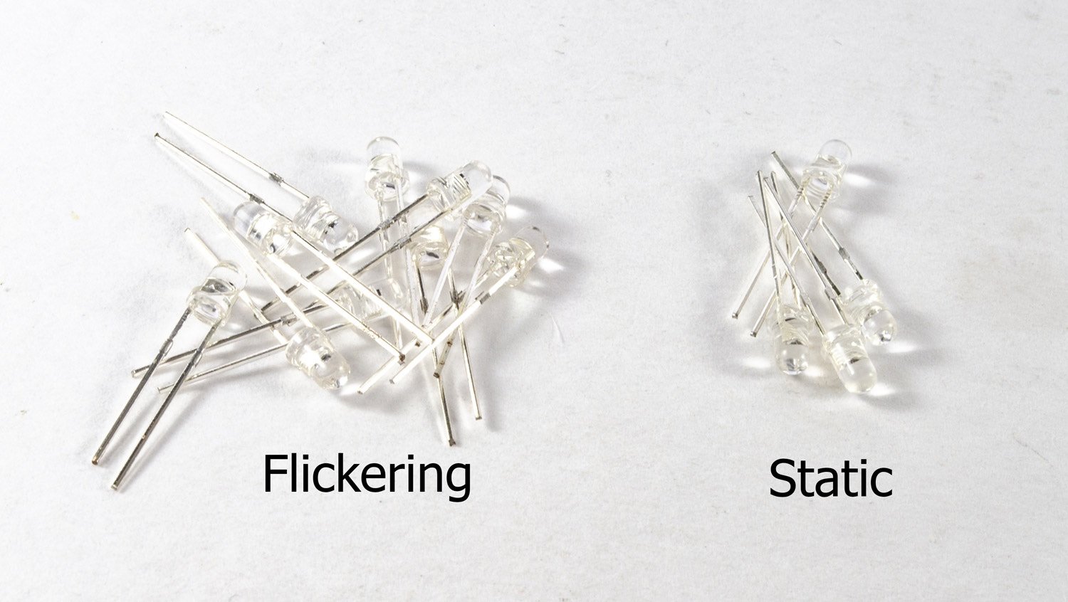
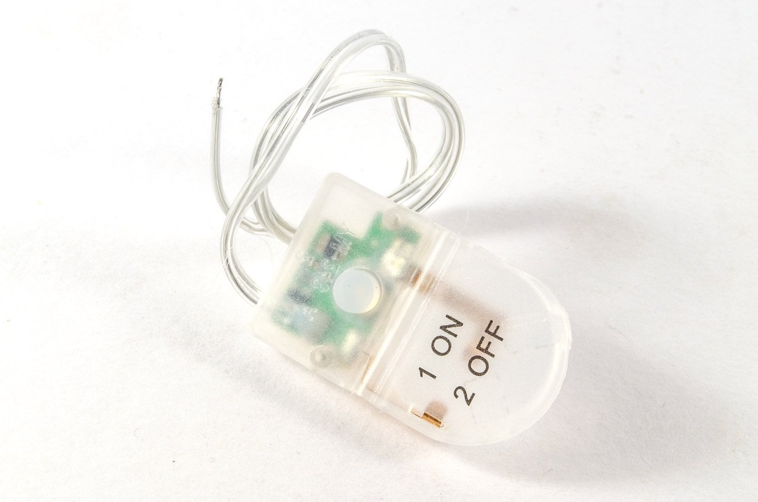
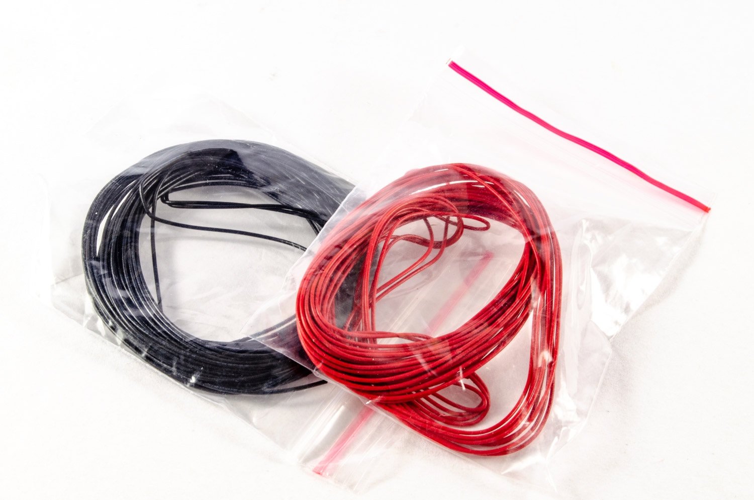
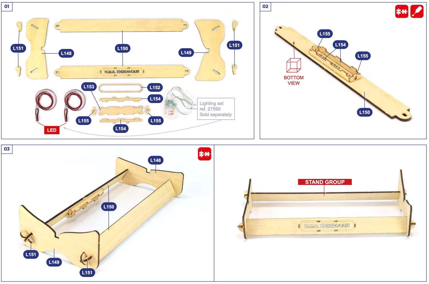
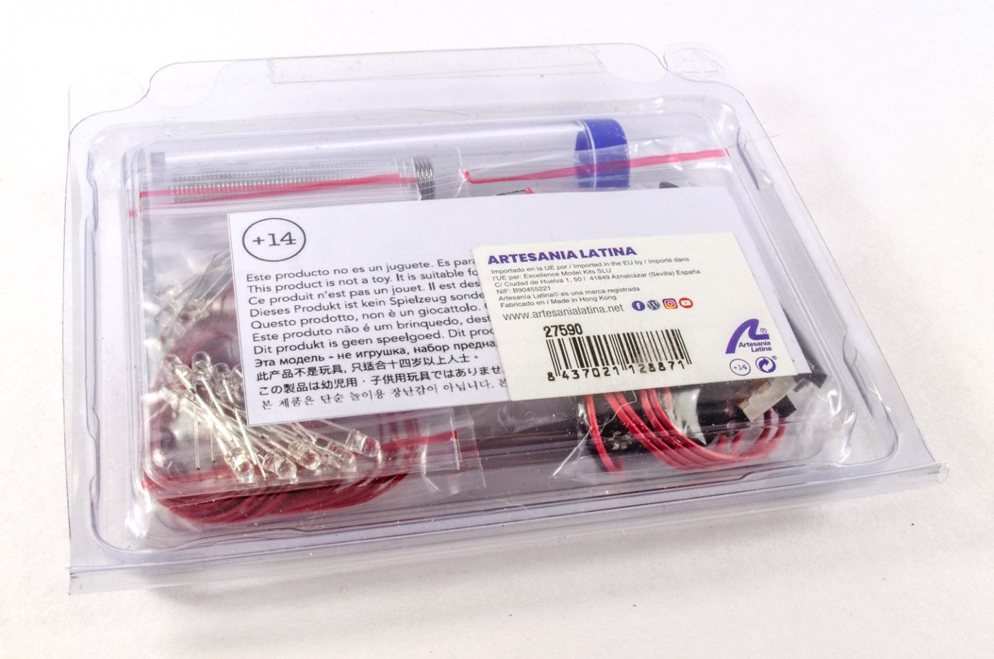
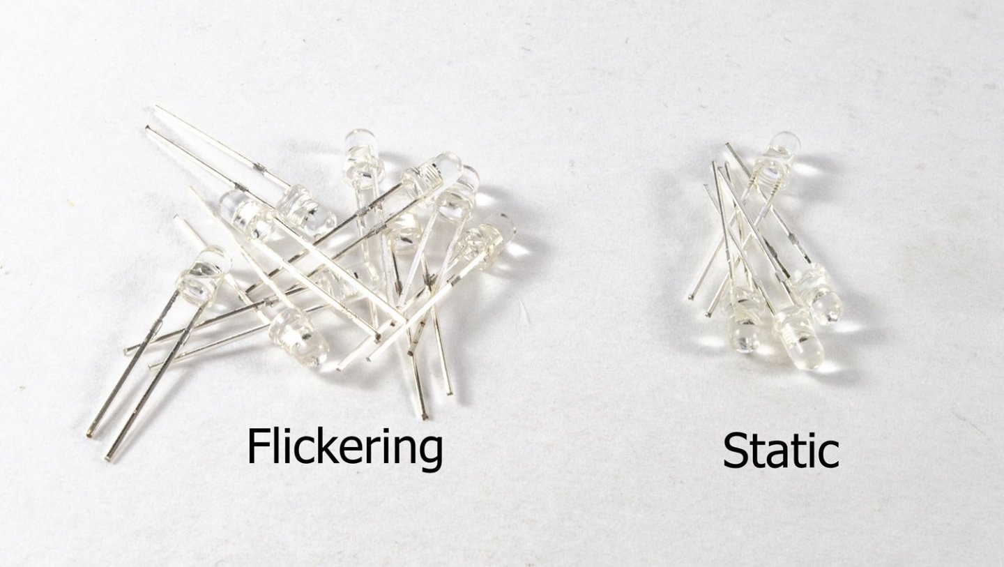
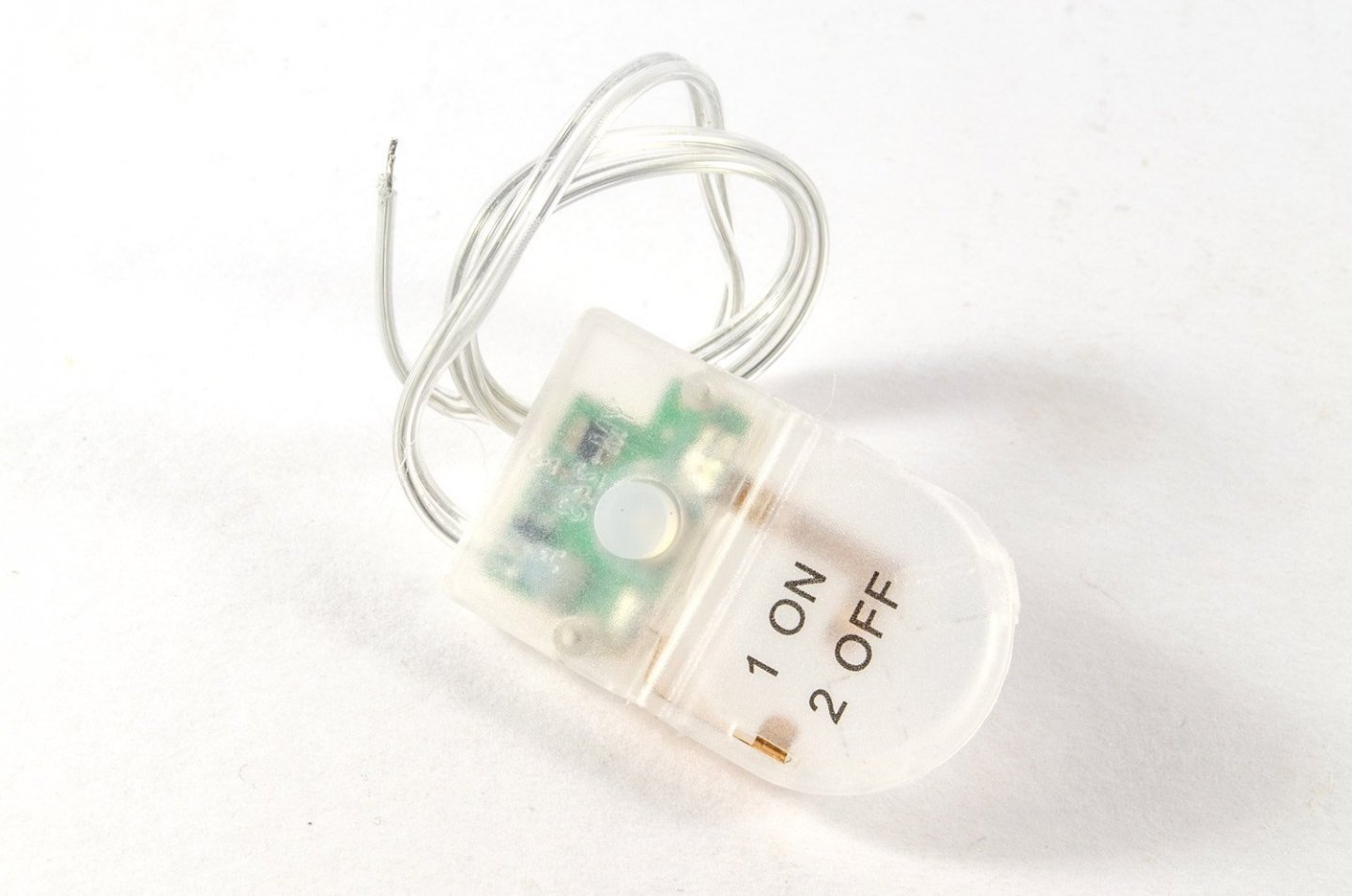
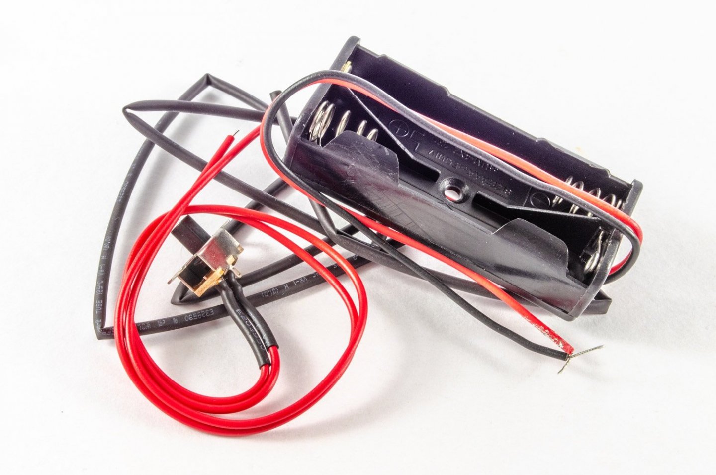
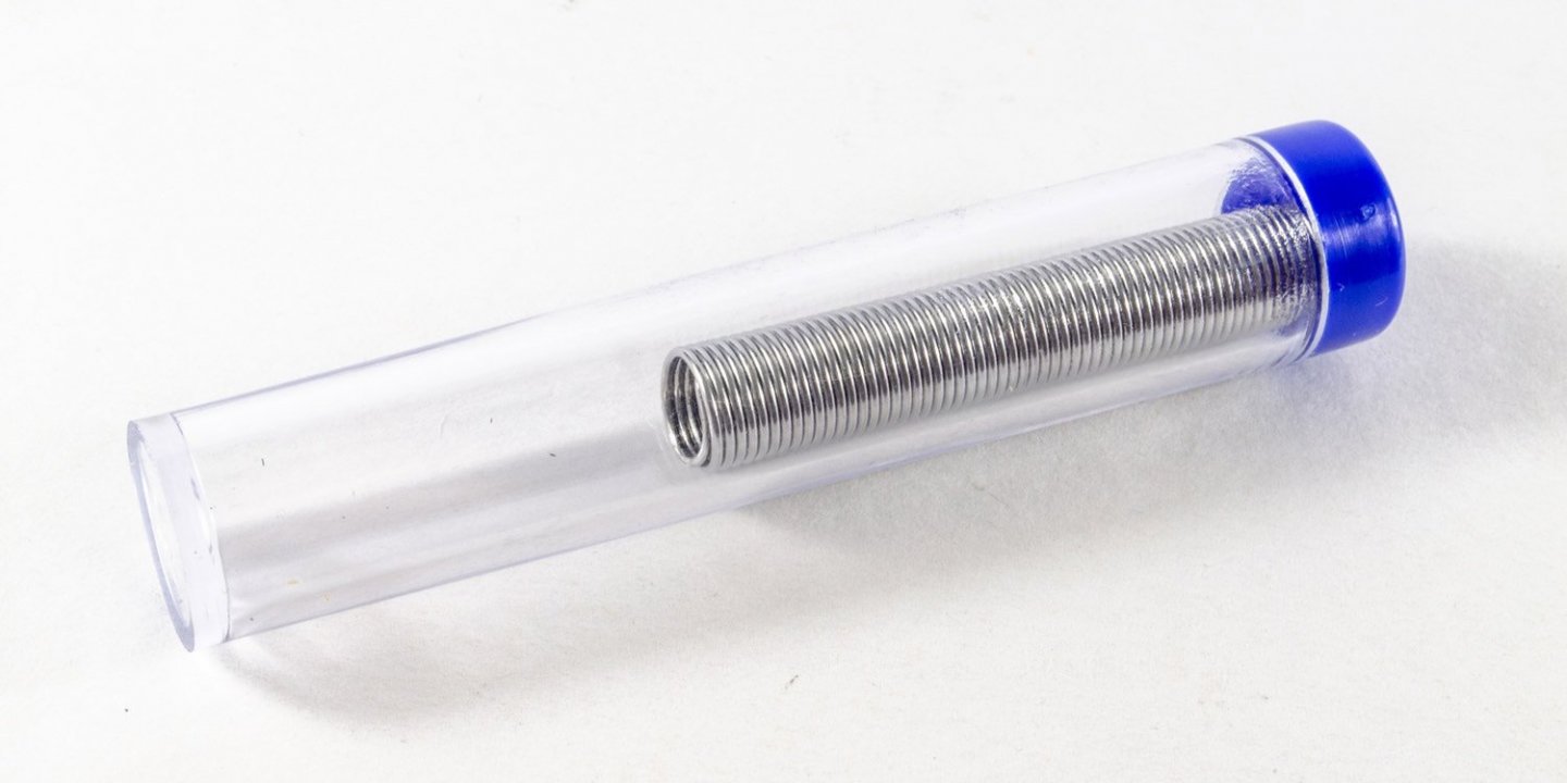
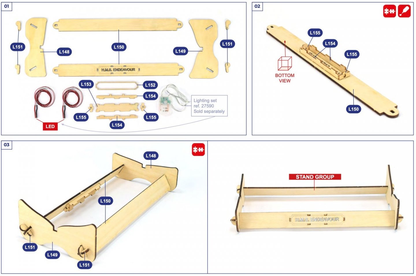
LED Lighting Set Artesania Latina Catalogue # 27590 Available from Artesania Latina for €20.65 If you have a hankering for fitting out your model with LEDs, then this set contains just what you need. AL's site states this: The LEDs are quite small, but not the so-called 'grain of rice' ones commonly seen. You also get a very generous amount of wire on both black and red, and more solder than you will ever need to wire up a large model. Two power sources are included. One of these is a regular battery pack, seen here with a separate switch and a nice quantity of heat shrink sleeve. A coin battery pack is seen here with a built-in switch. This is actually shown for use in their HMS Endeavour kit, hidden in the stand to illuminate the hollow name box area. A nice touch. New AL kits also contain holes for the wires to run, and installation is shown in the manuals. A generous amount of solder is also included. This is tin solder due to the problems that now exist with regulations in obtaining lead solder (which I preferred). Strangely enough, no instructions are supplied with this, so I'm unsure whether the LEDs need a ballast resistor fitting to them. My thanks to Artesania Latina for the sample shown here. To purchase directly, click the link at the top of this article. You may also be able to buy this set from your favourite hobby retailer.


-
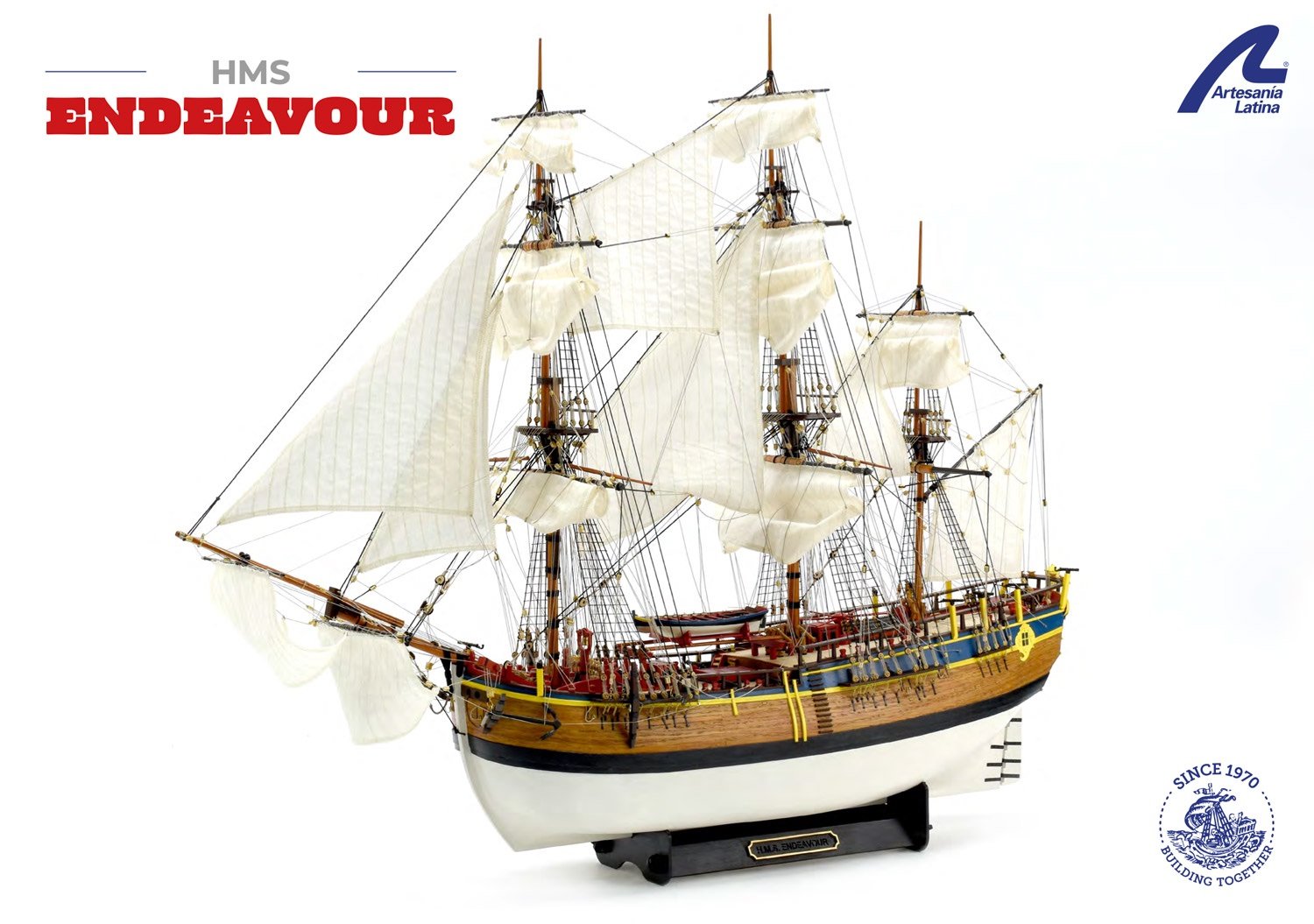
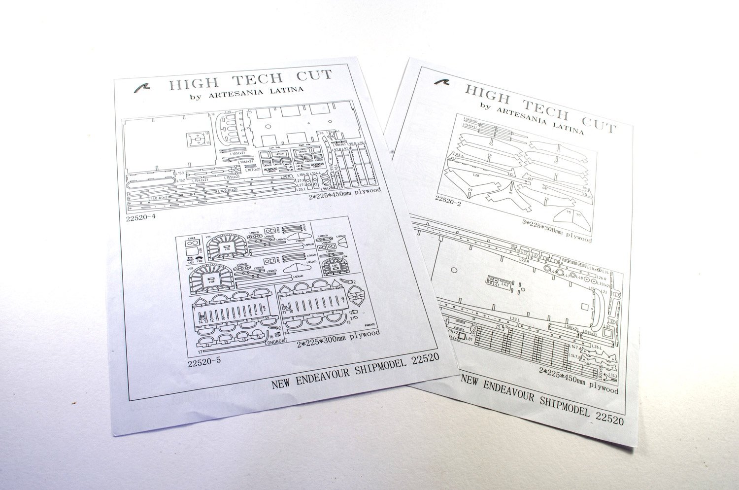
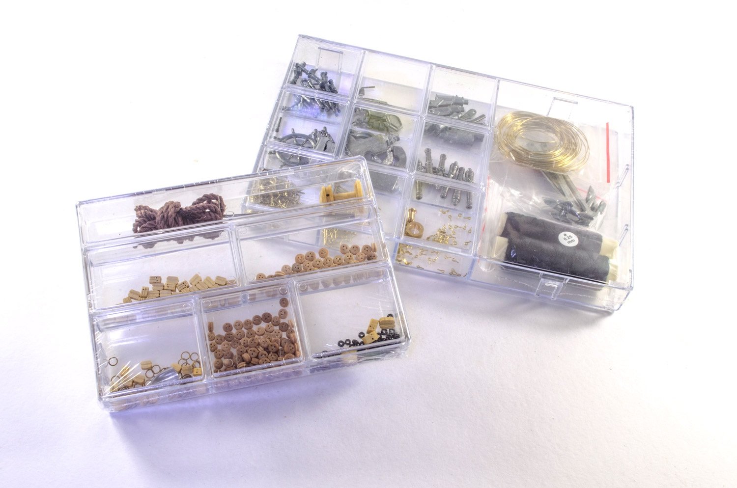
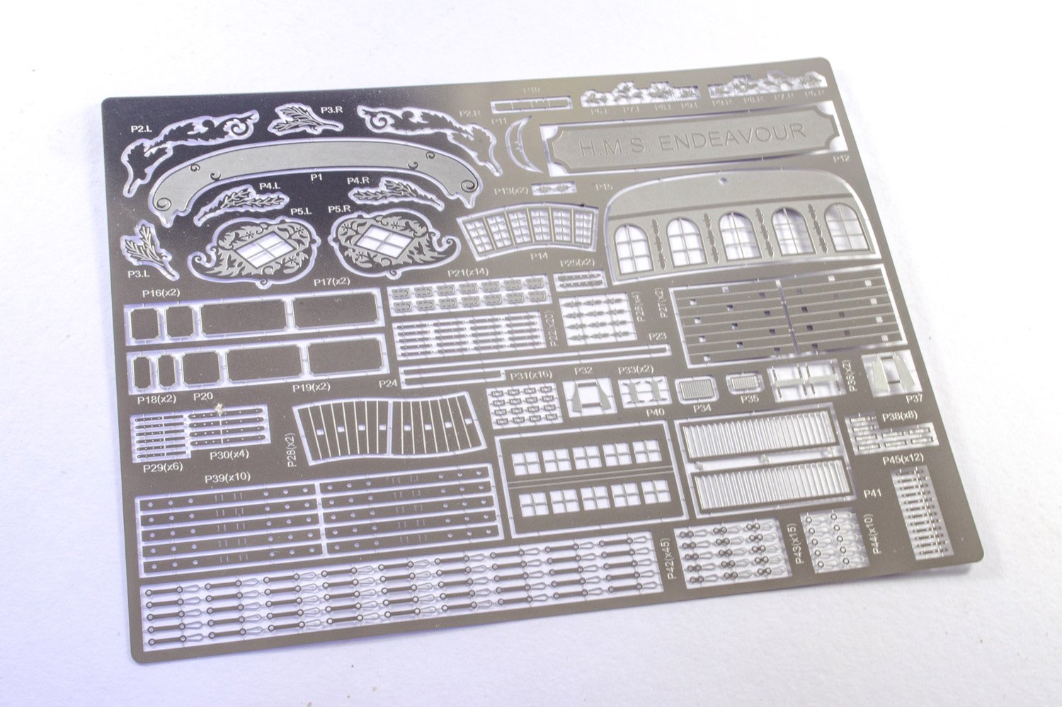
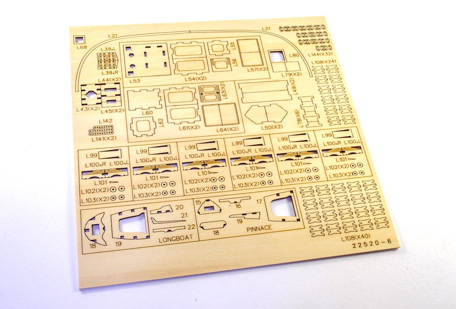
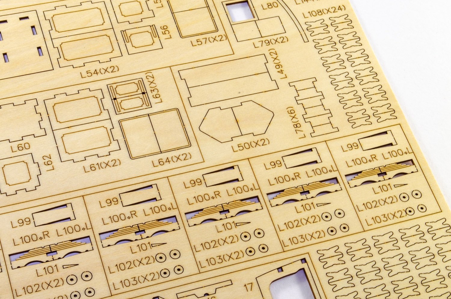
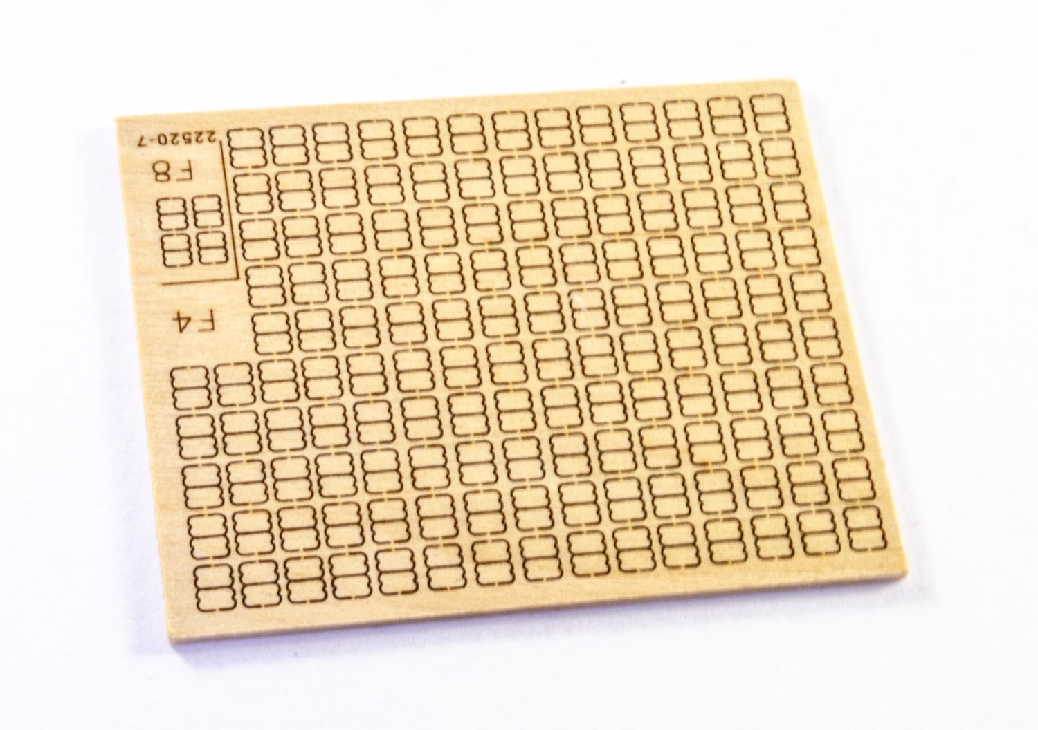
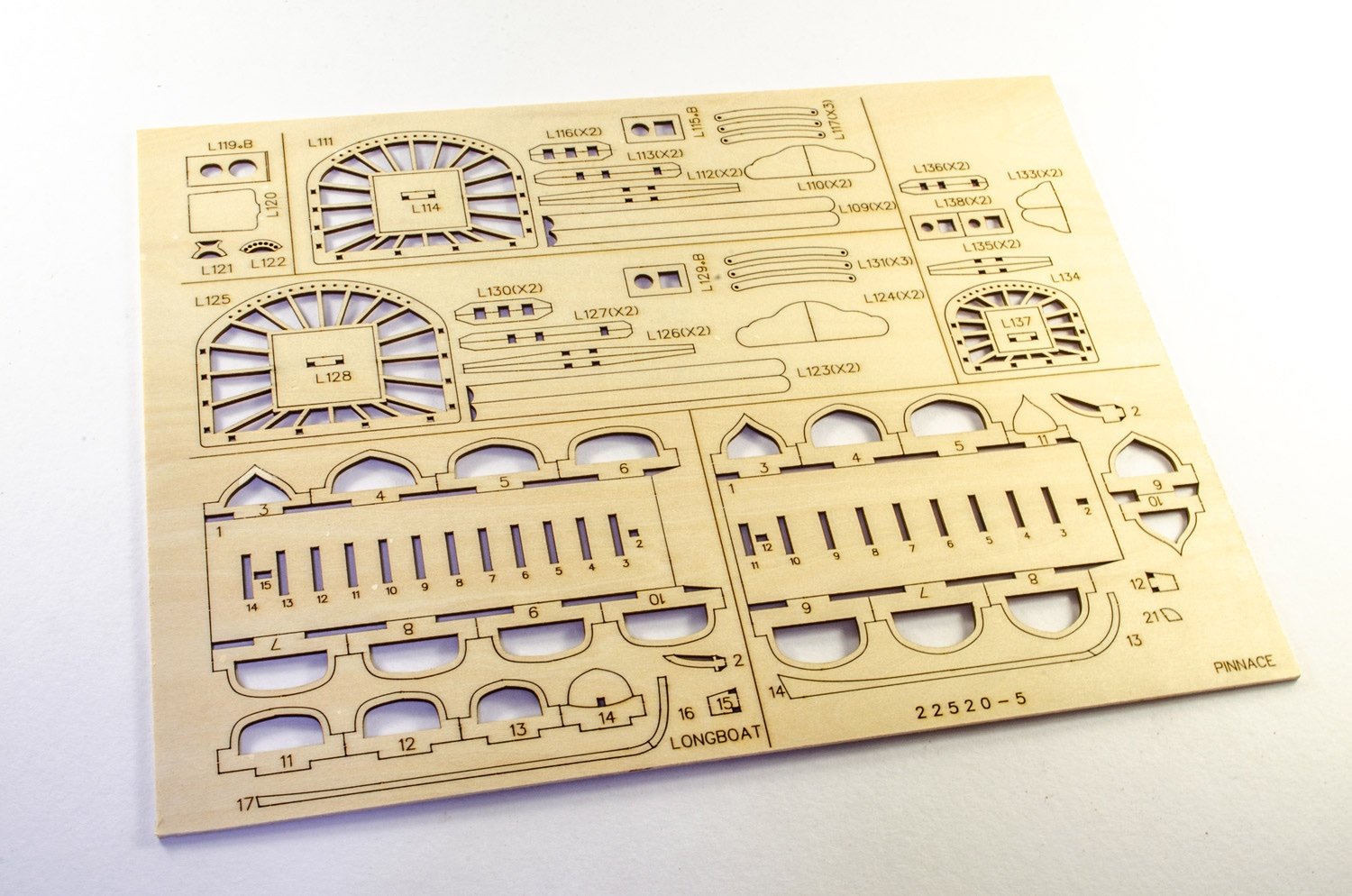
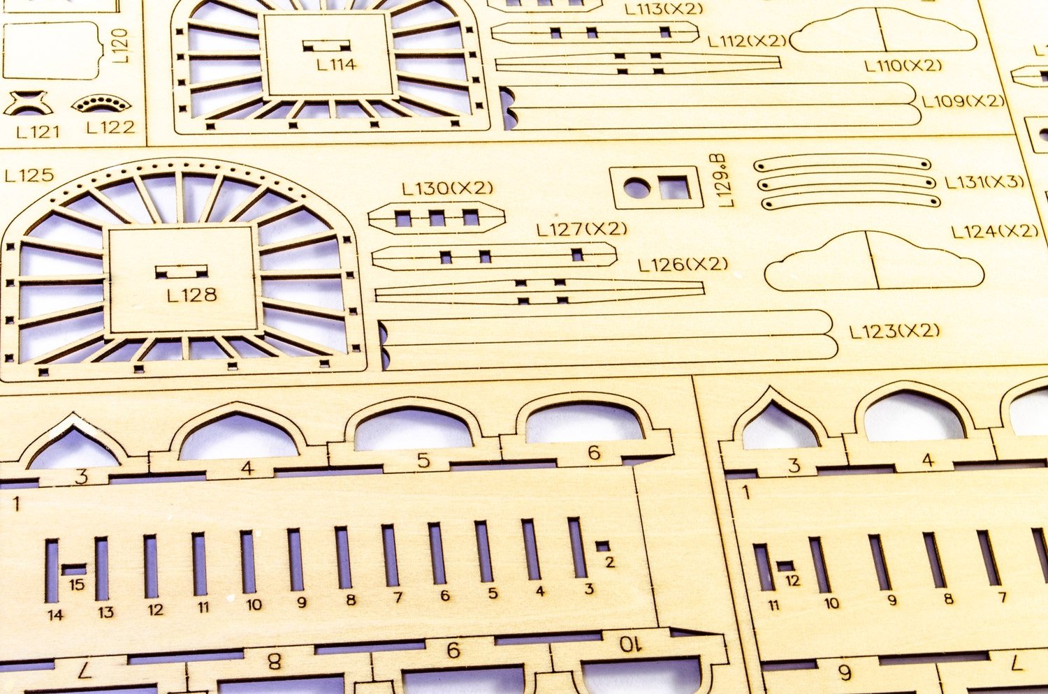
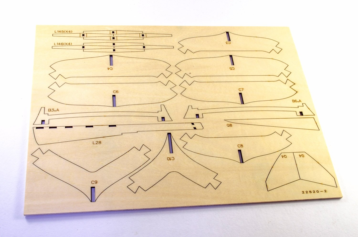
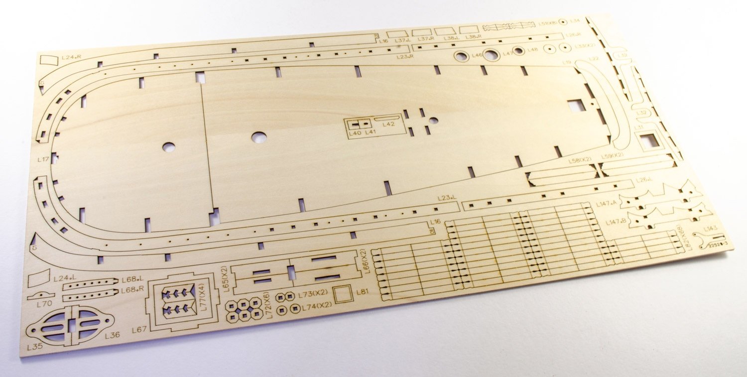
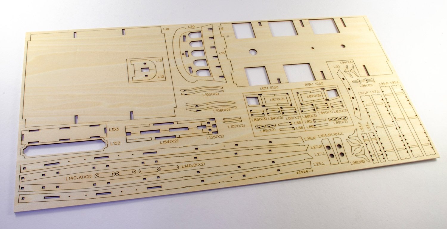
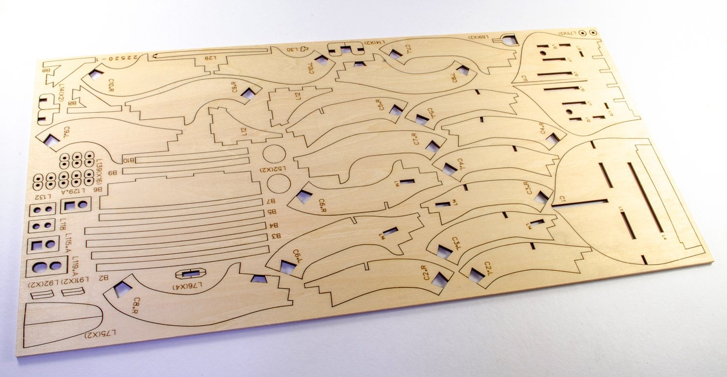
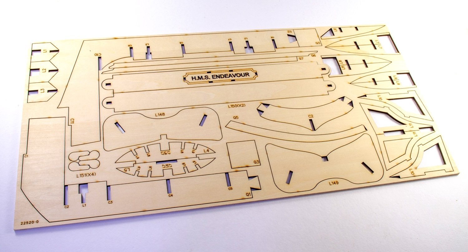
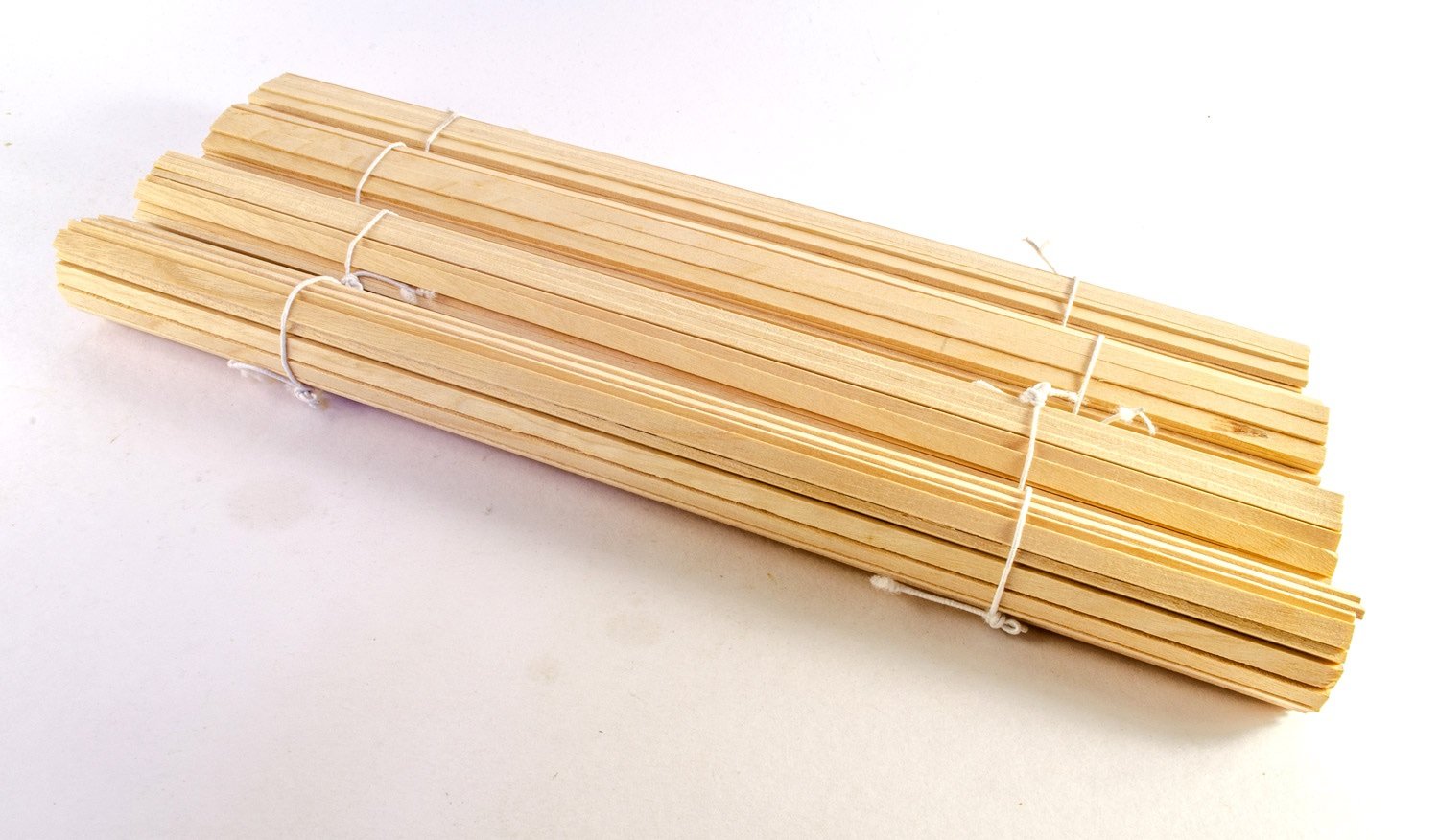
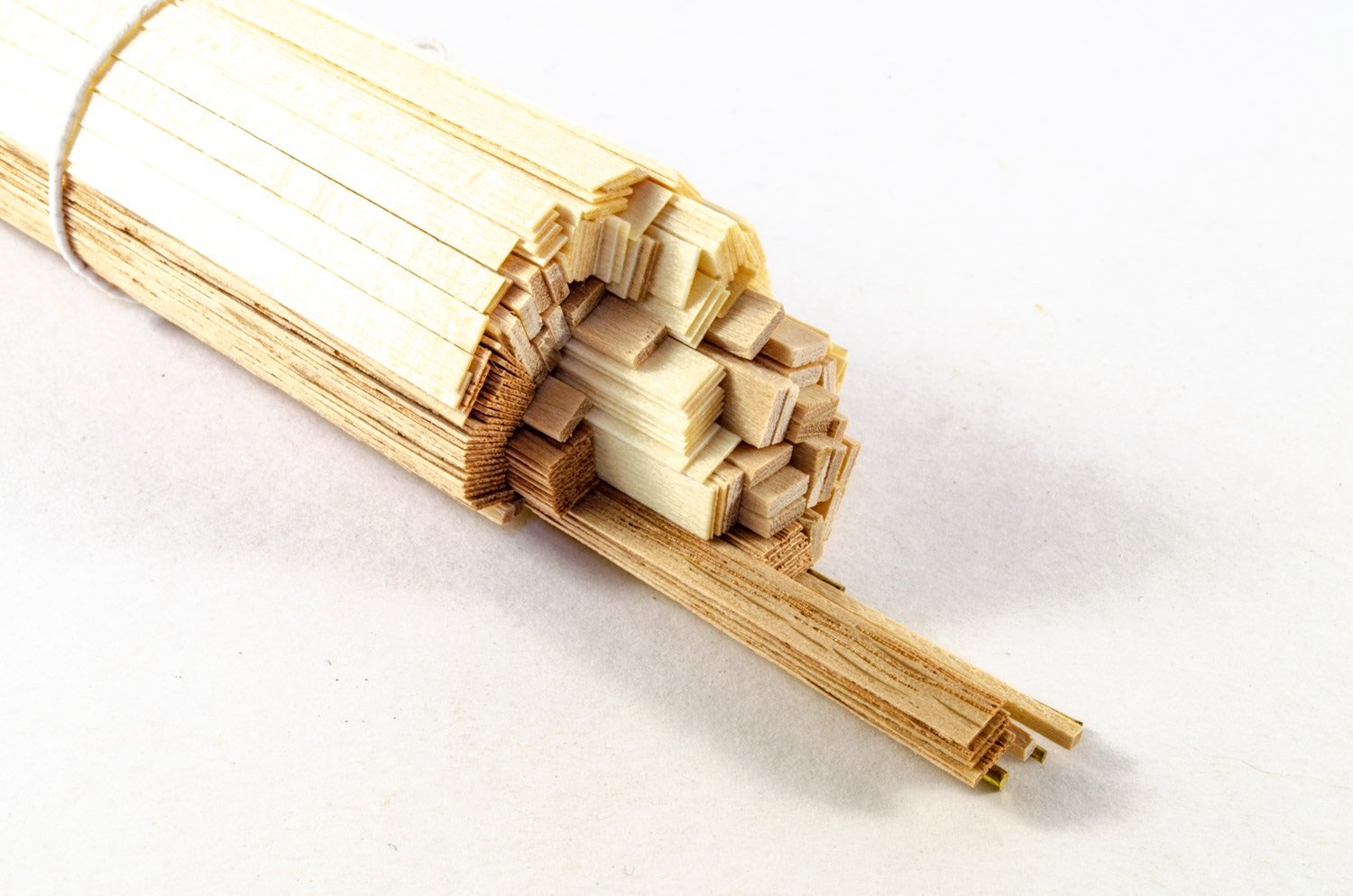
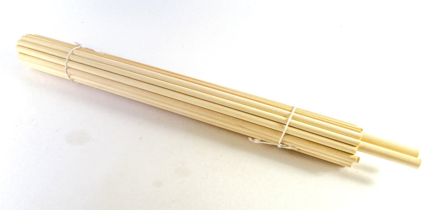
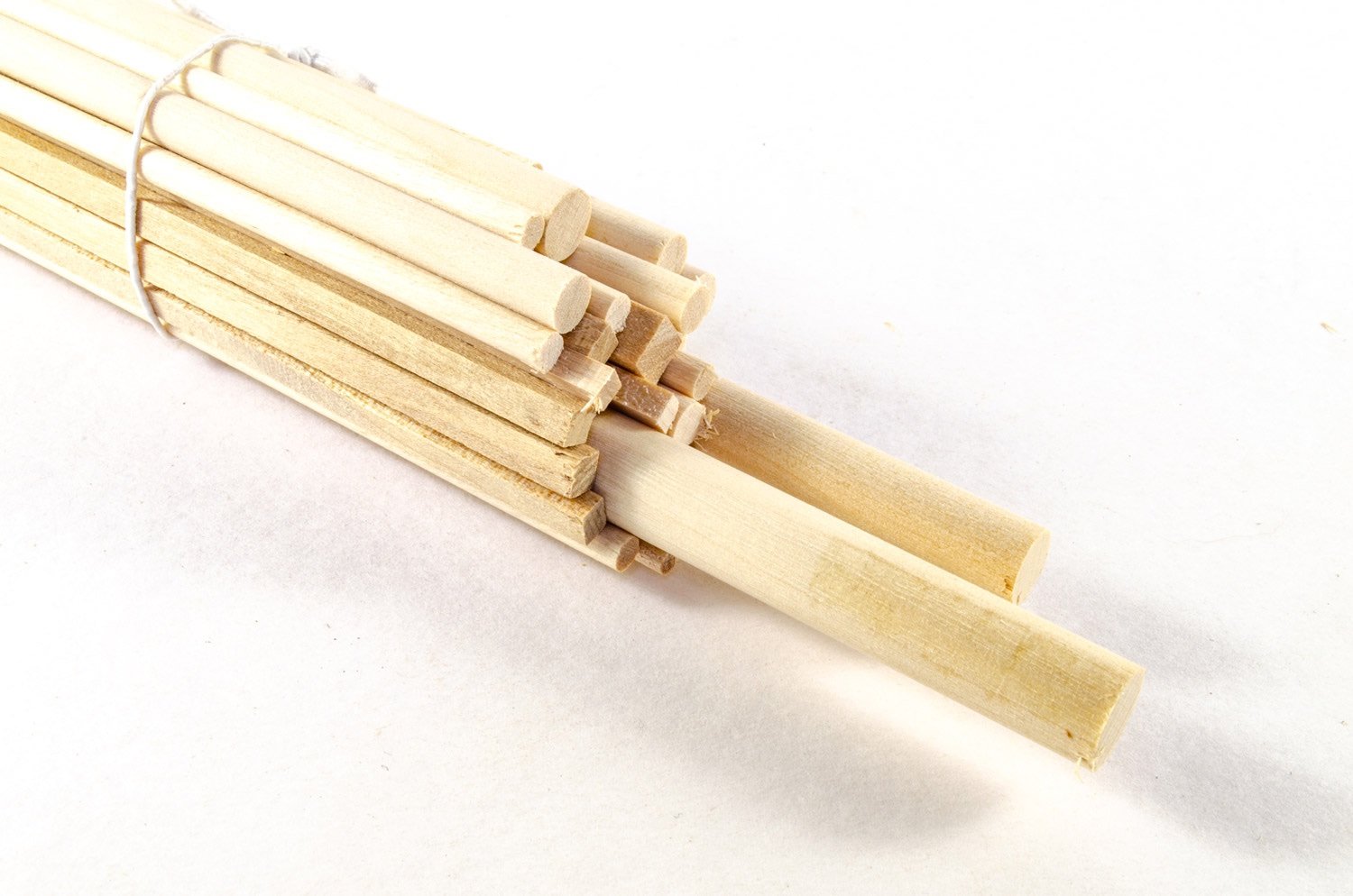
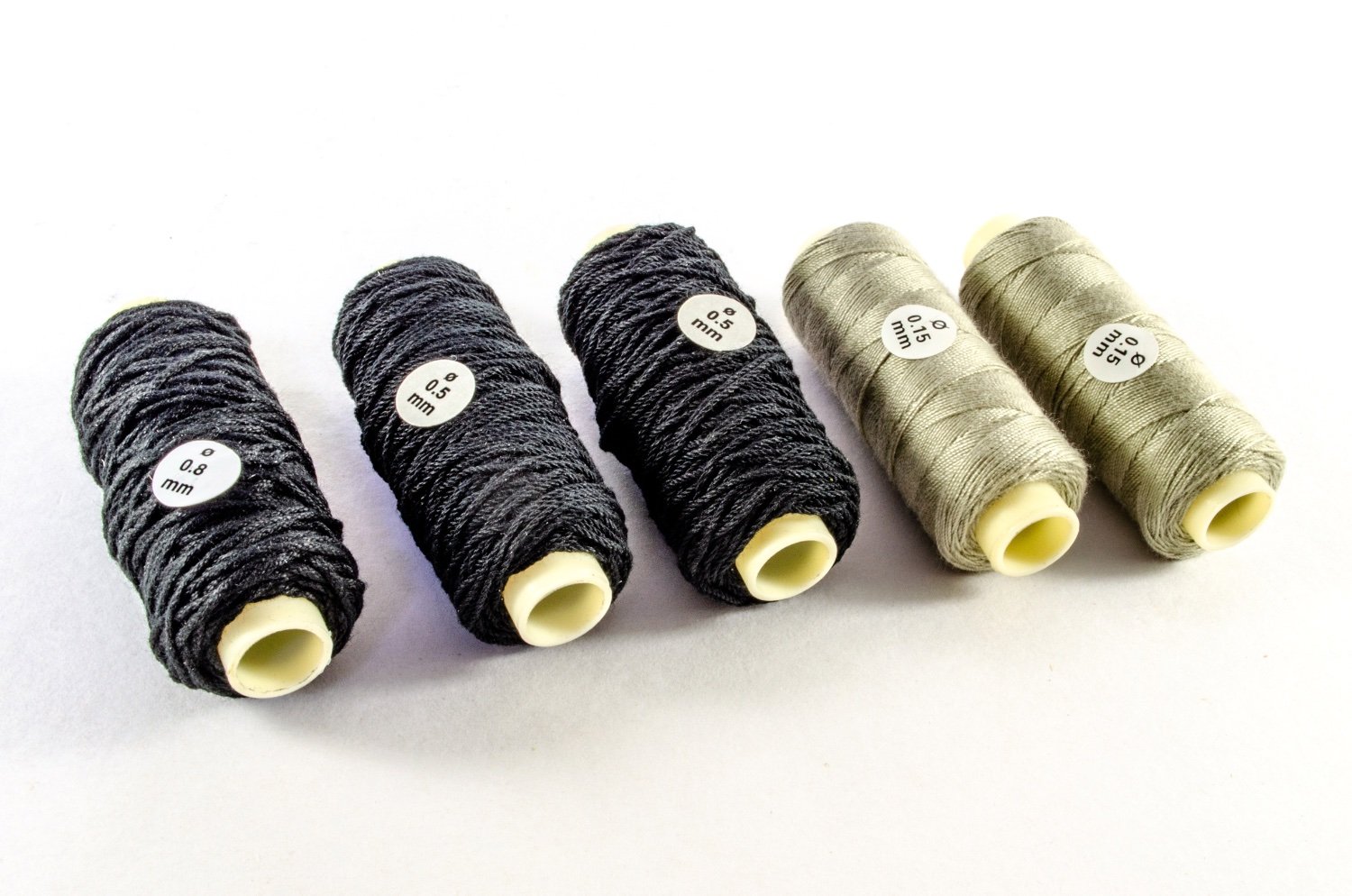
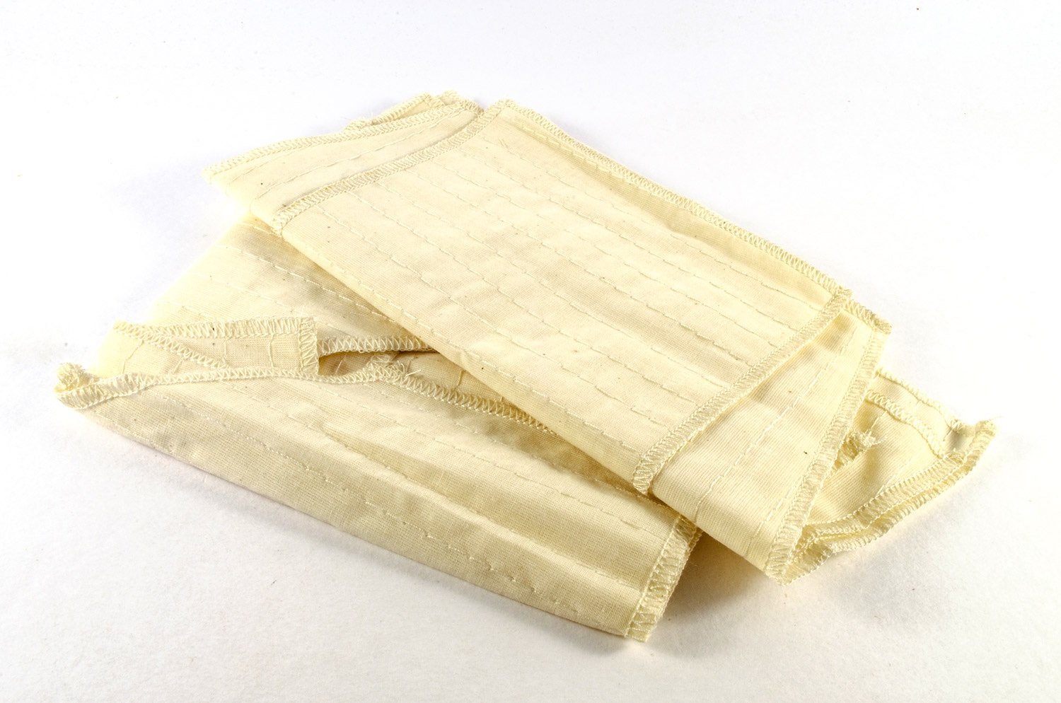
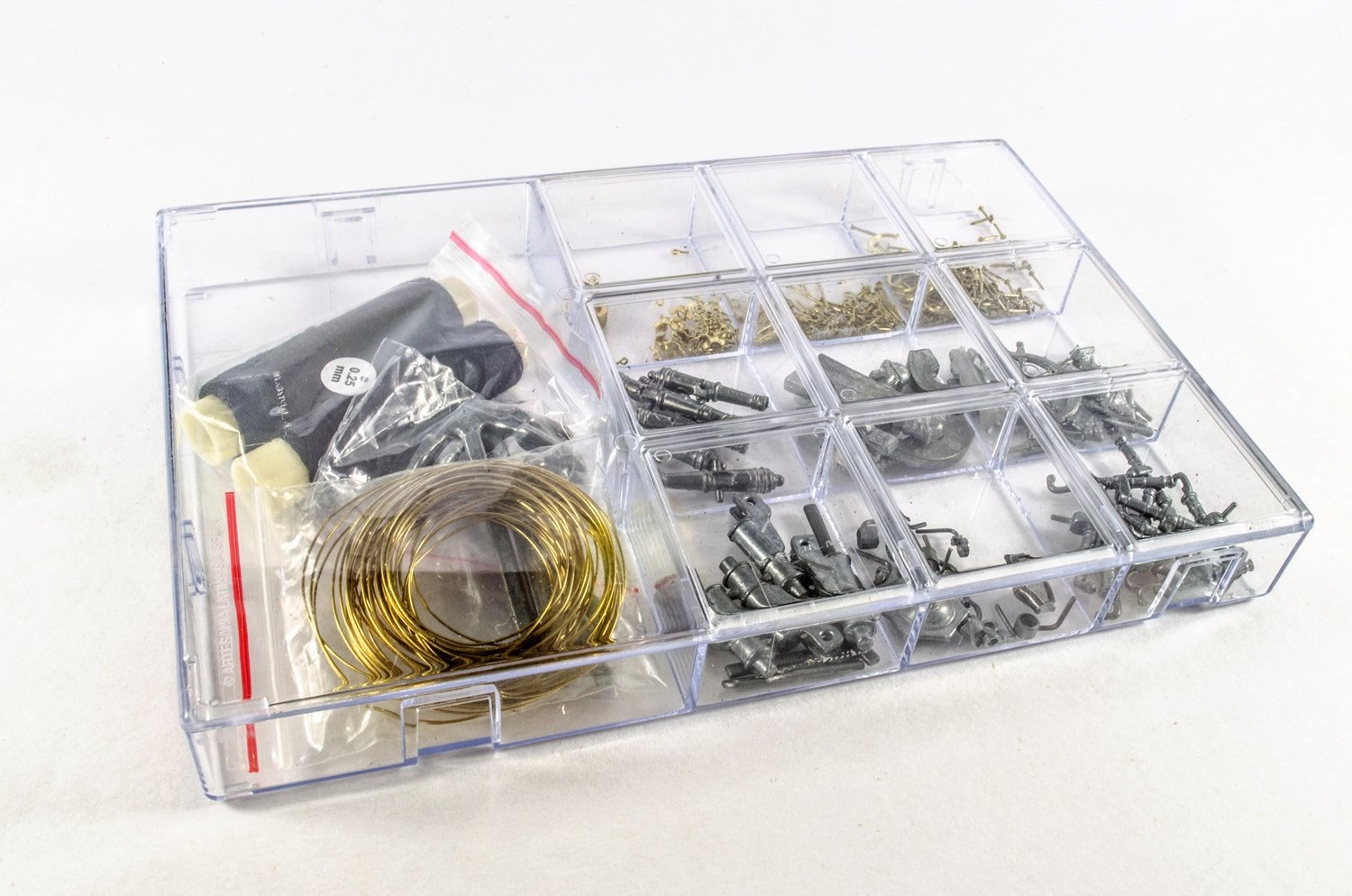
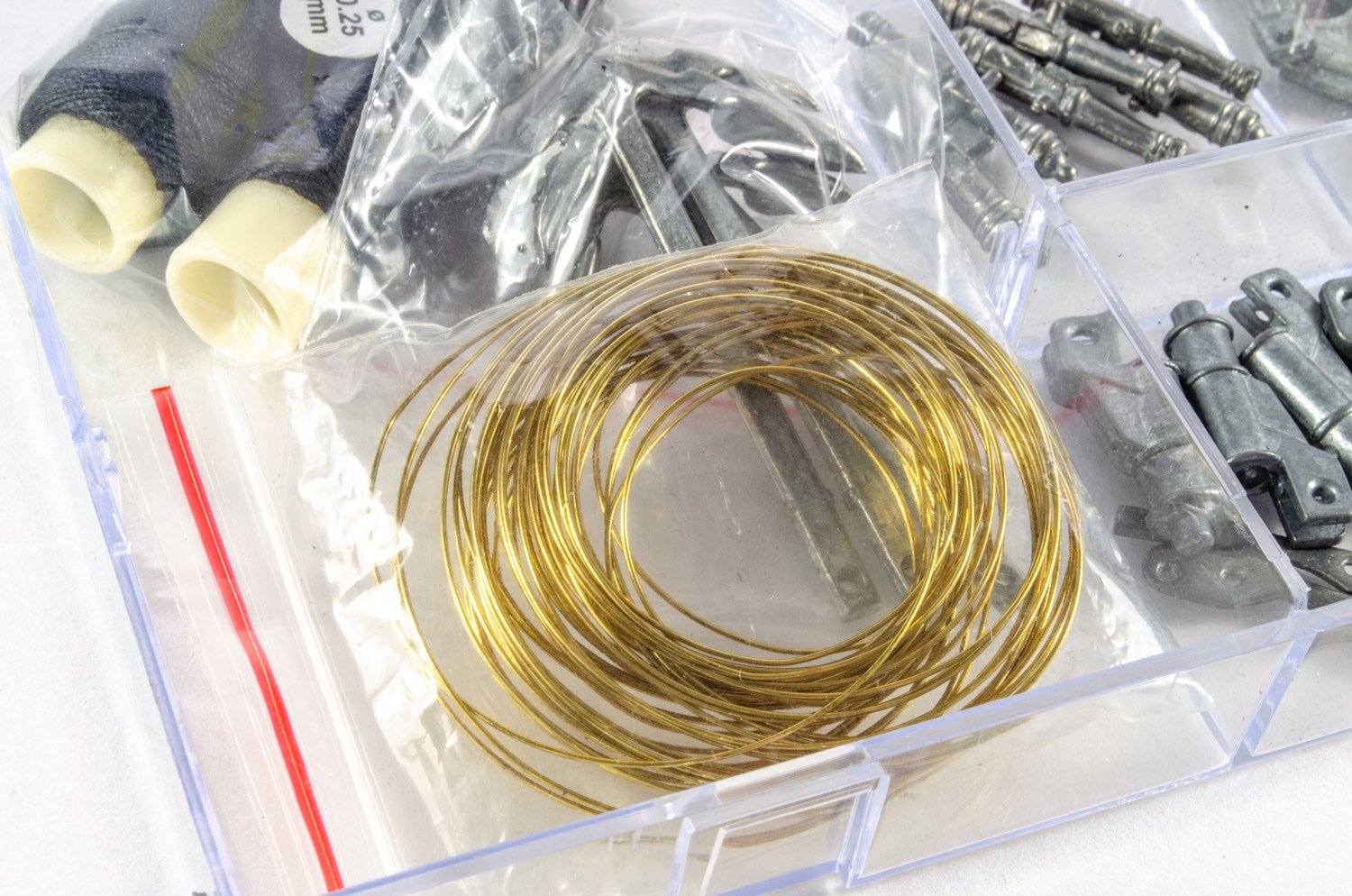
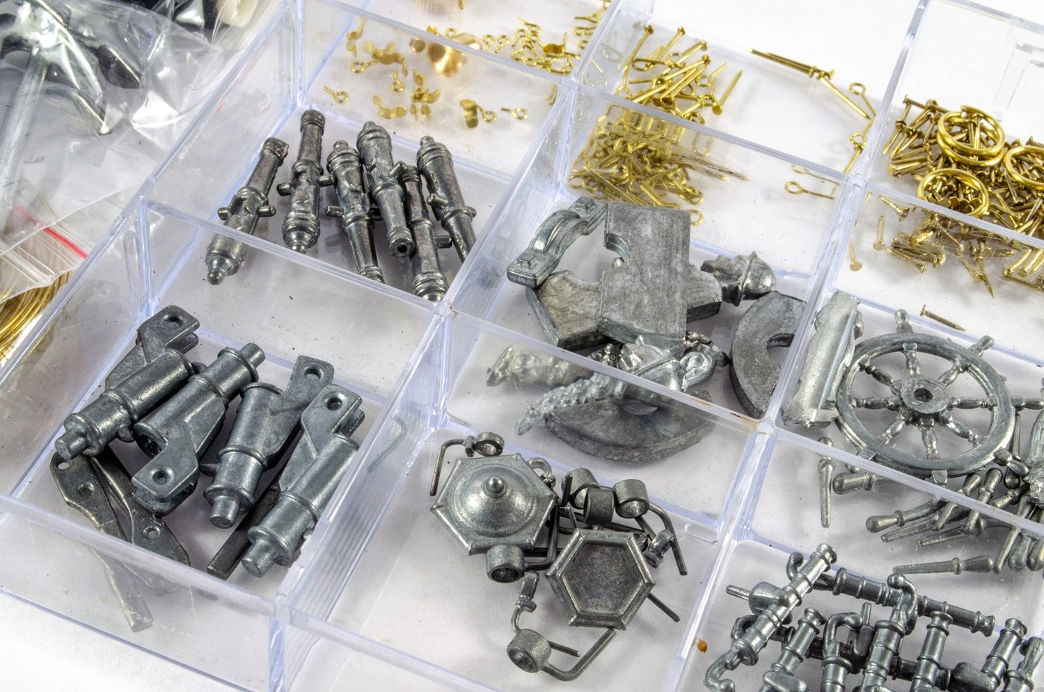
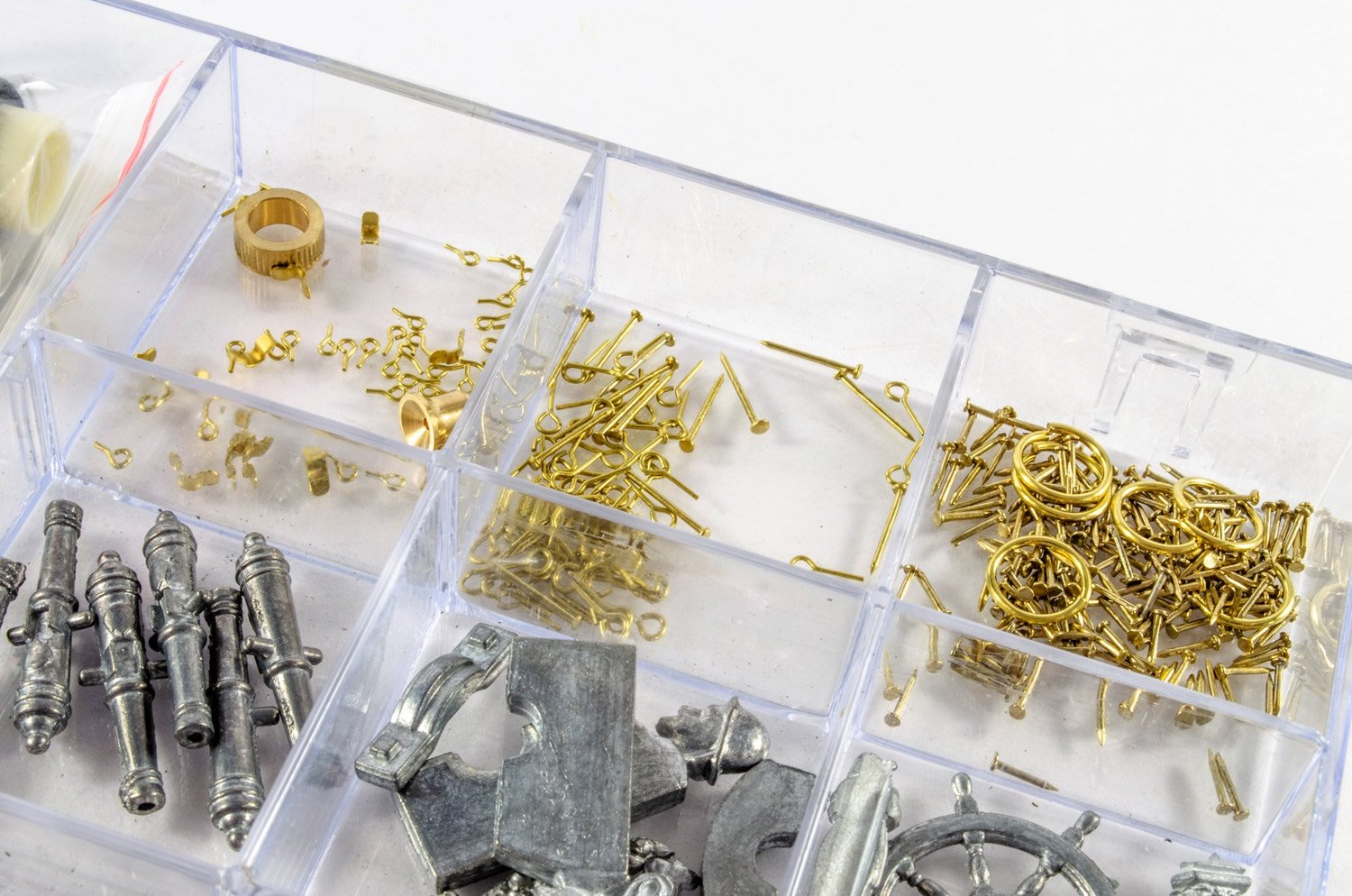
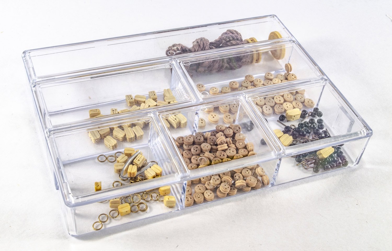
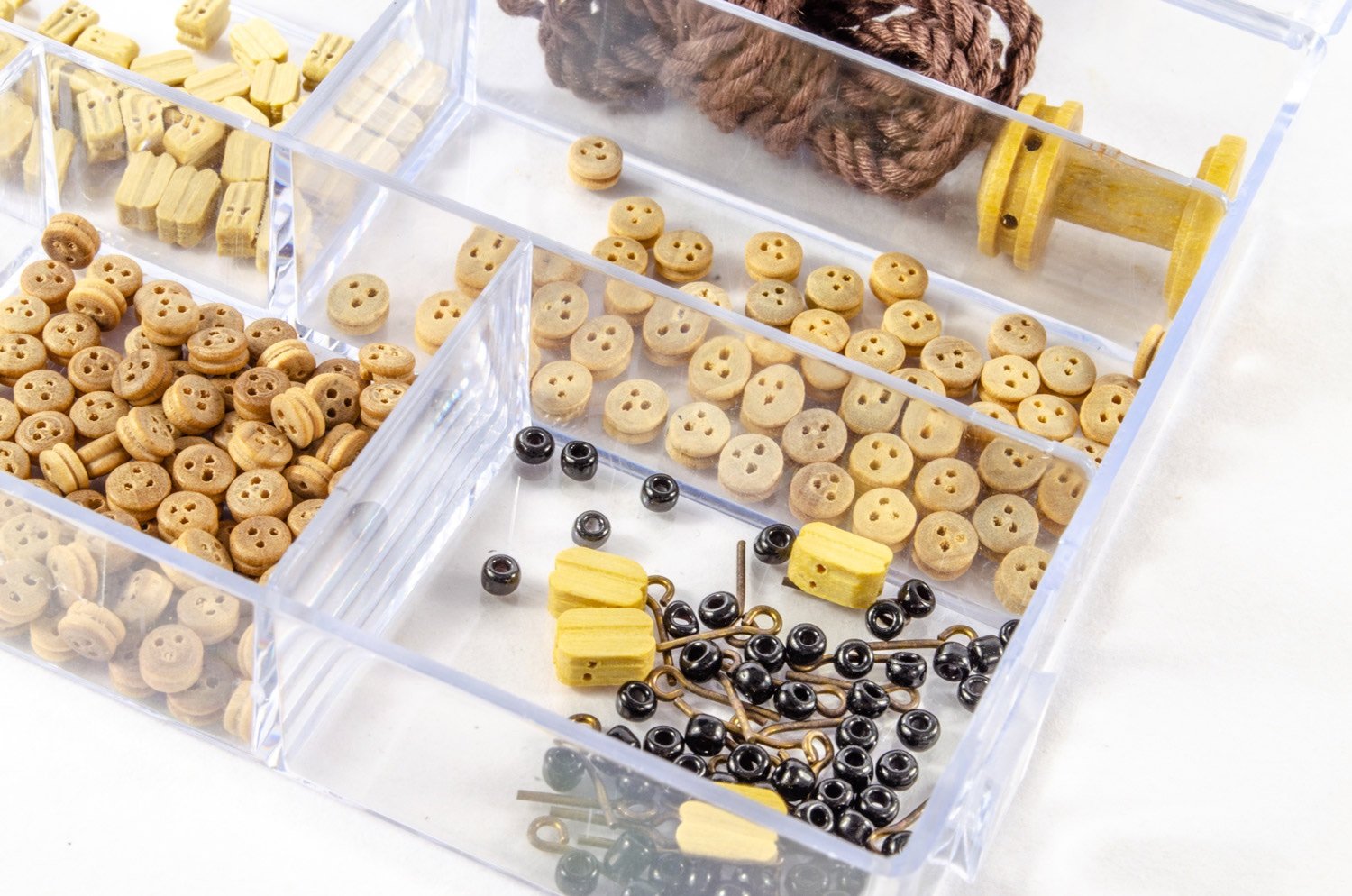
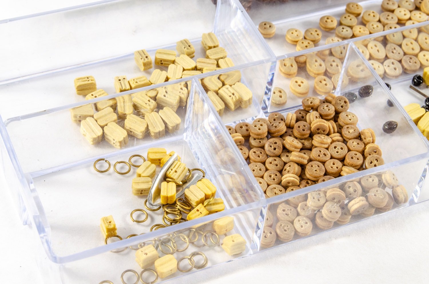
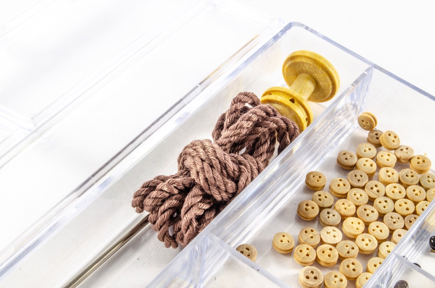
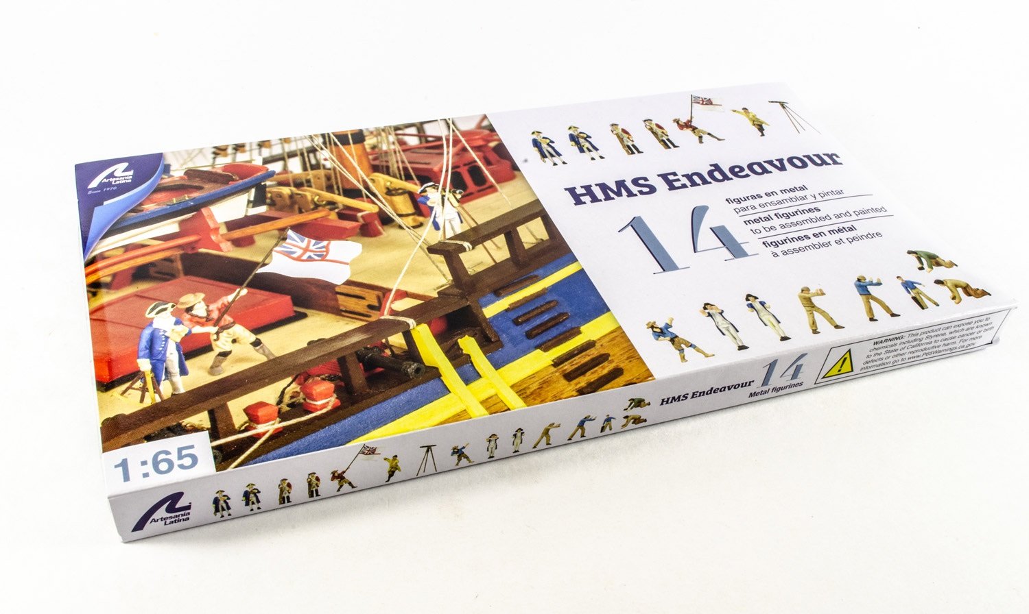
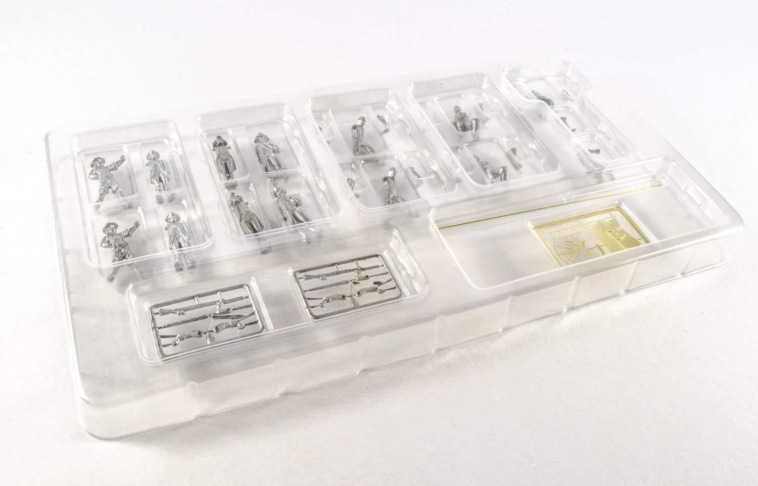
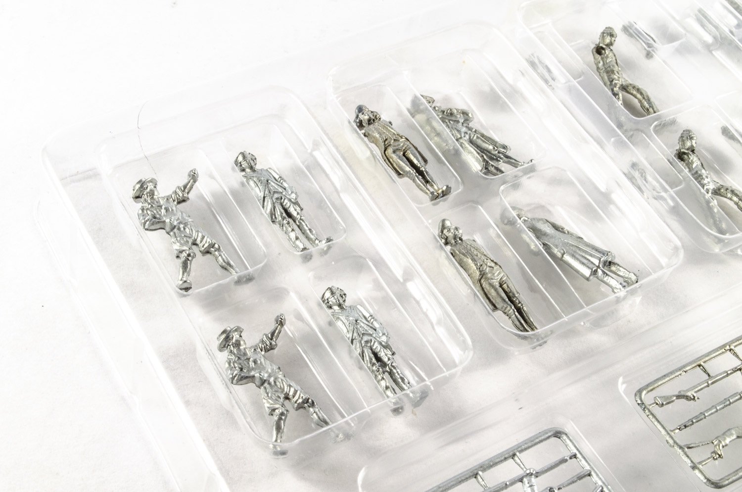
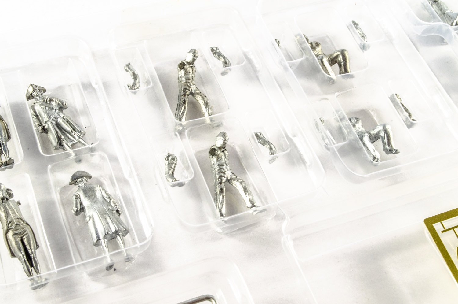
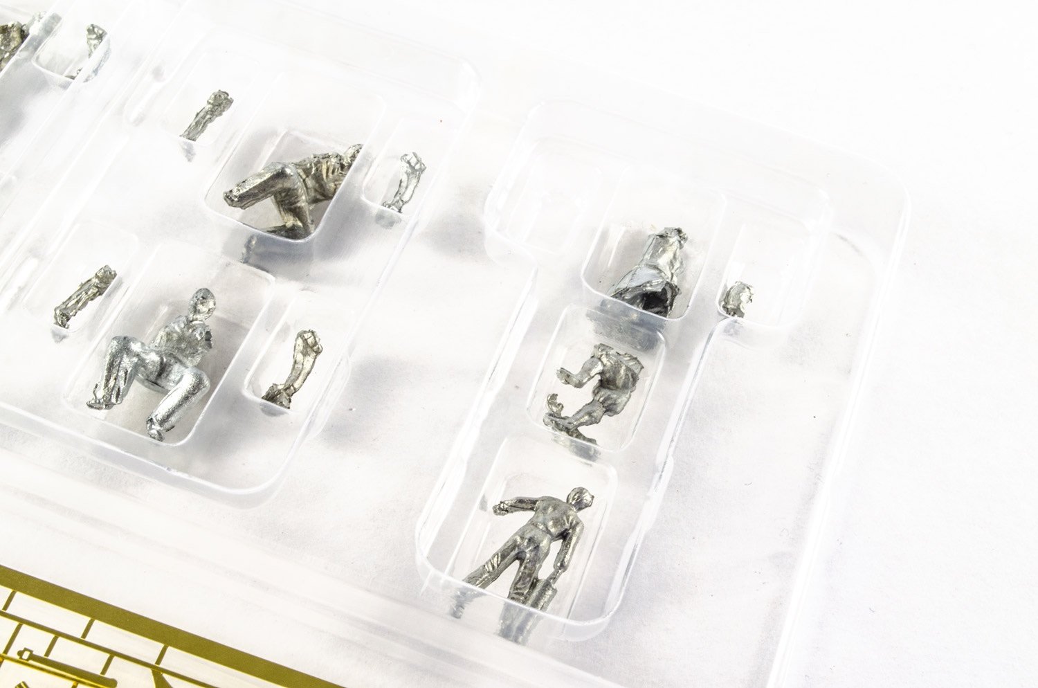
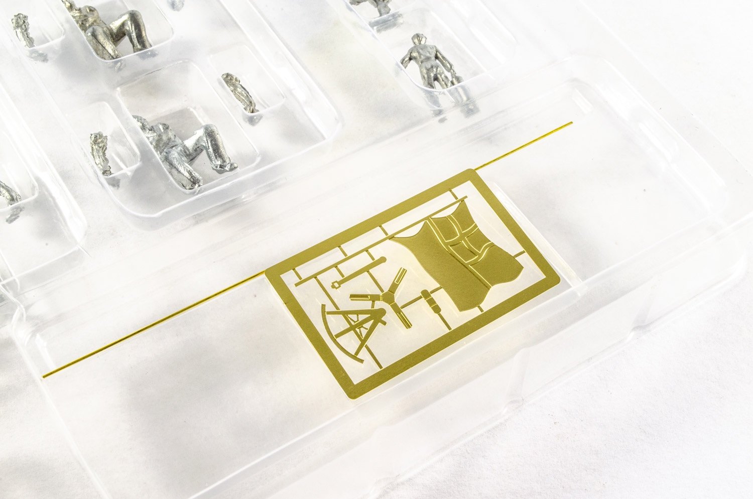
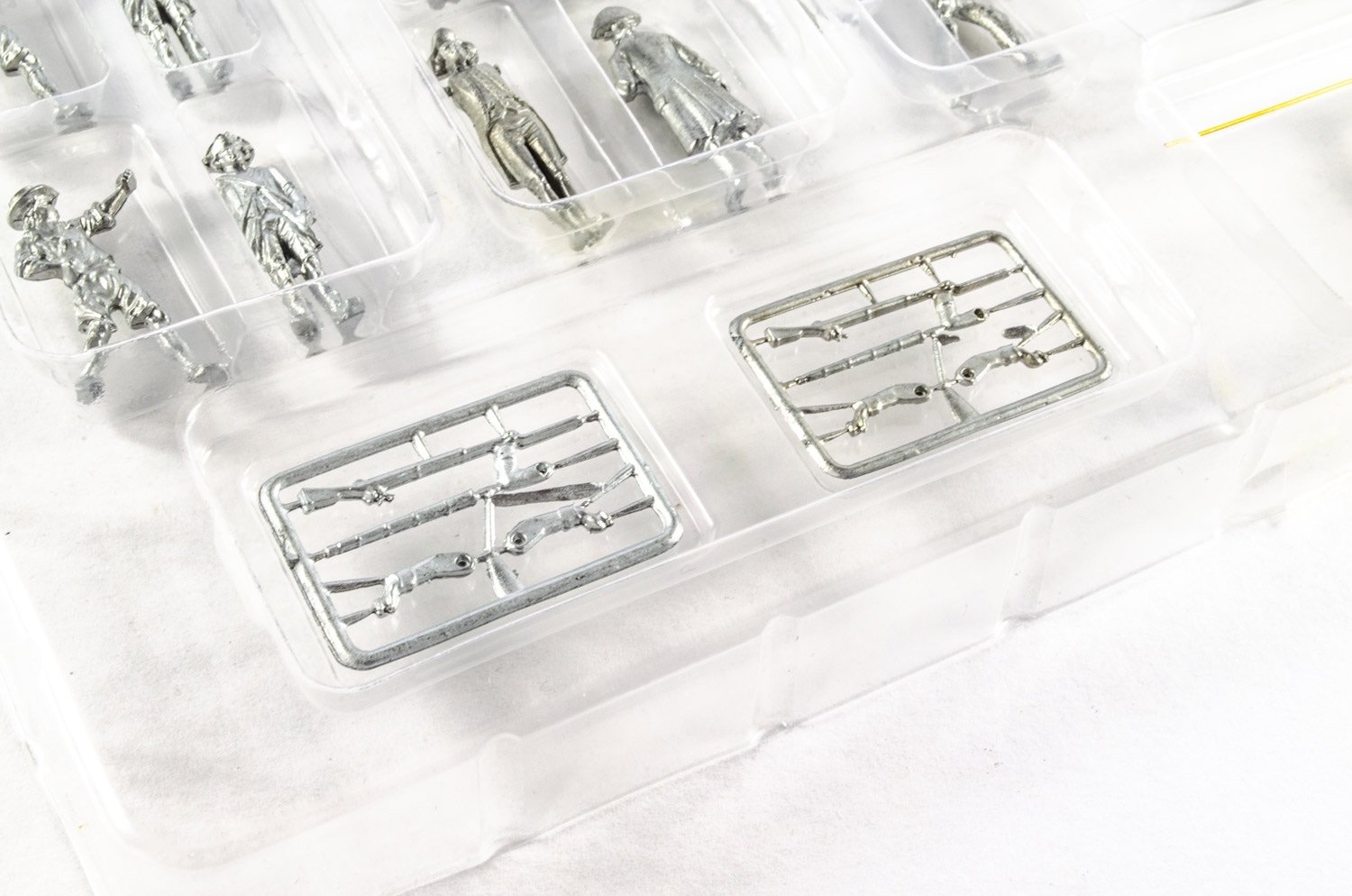
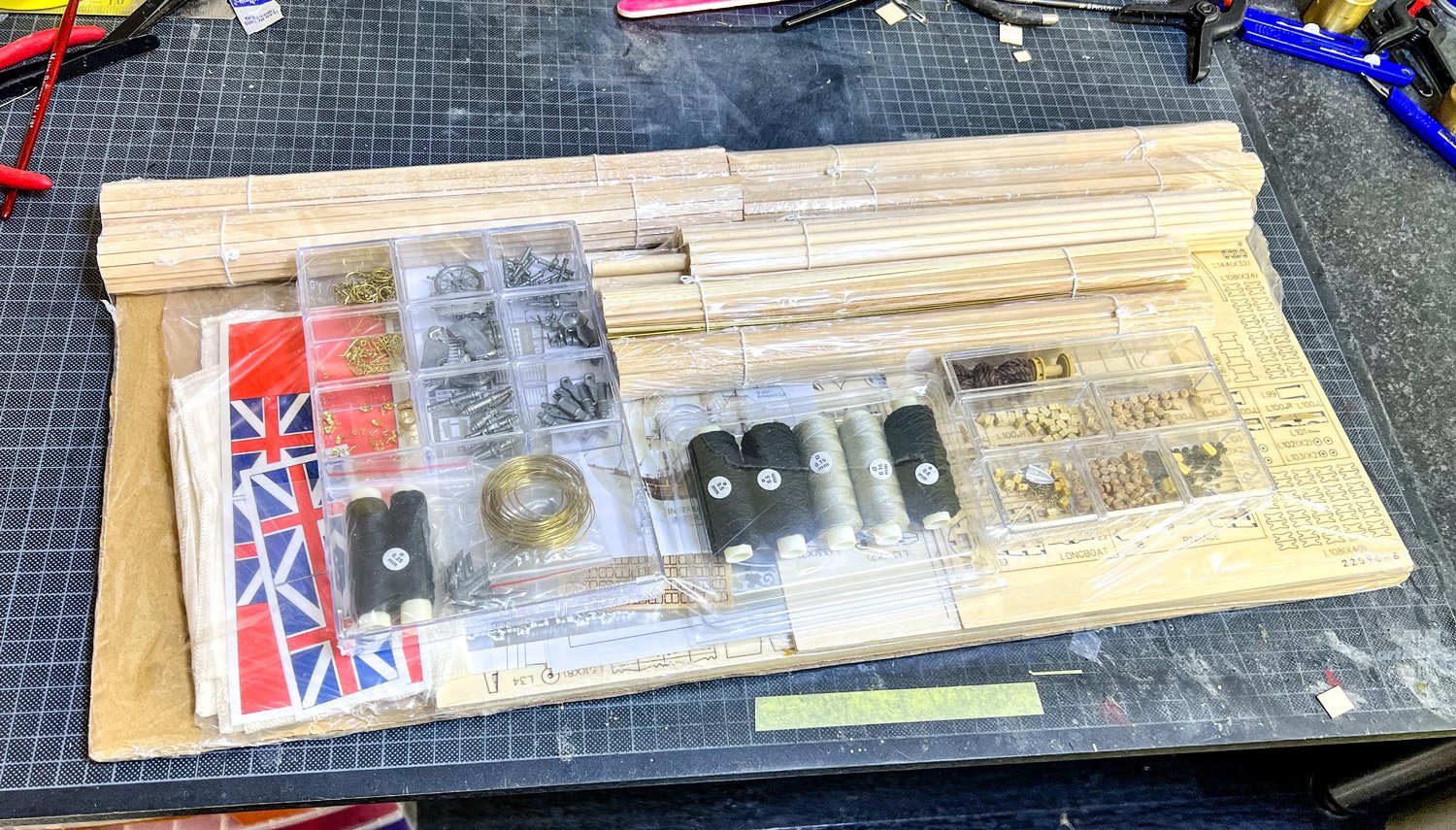
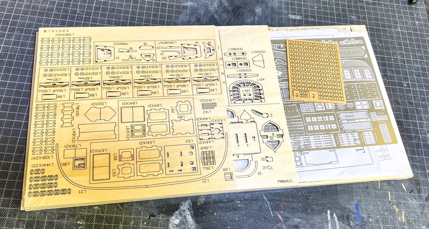
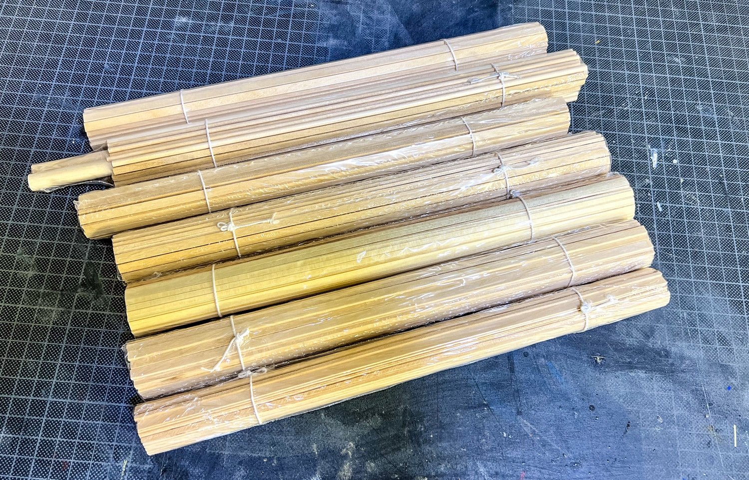
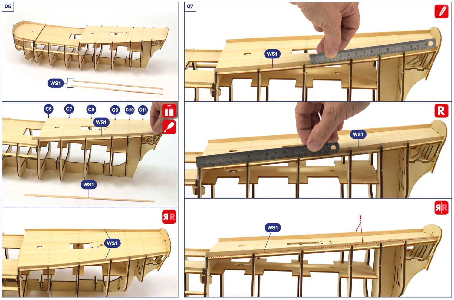
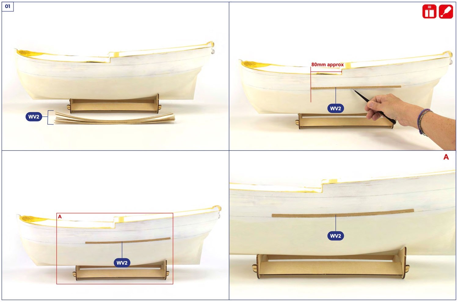
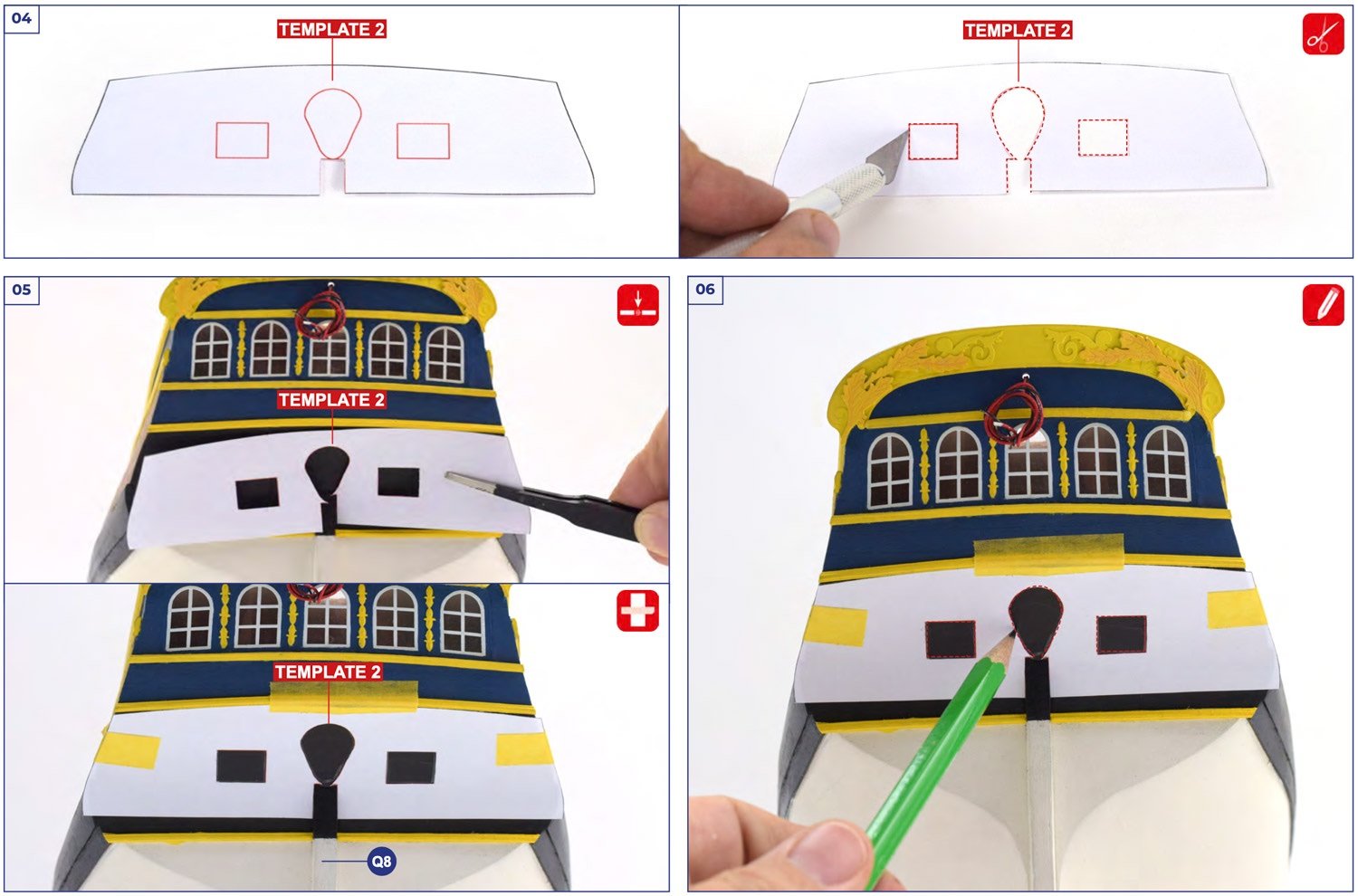
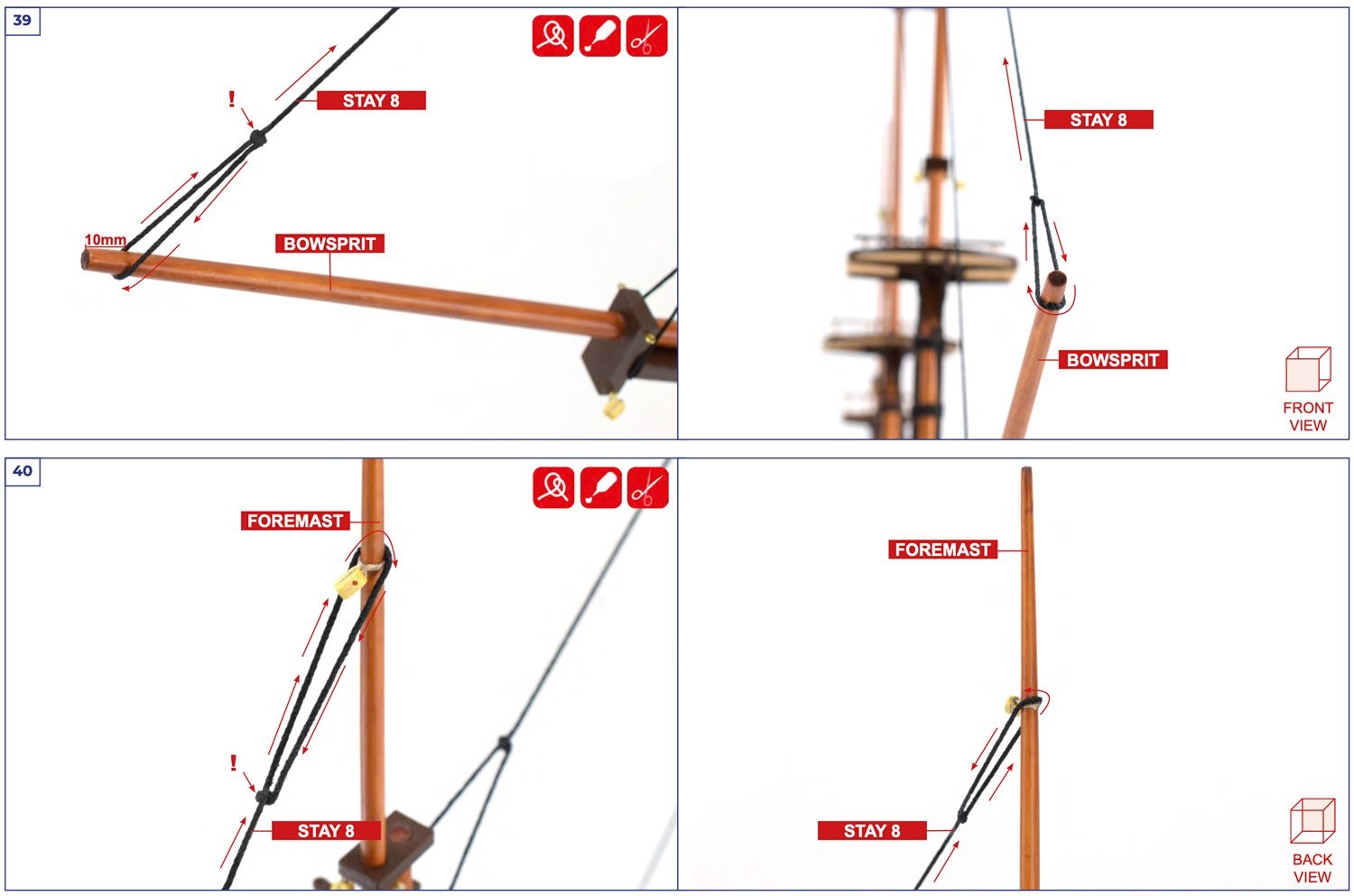
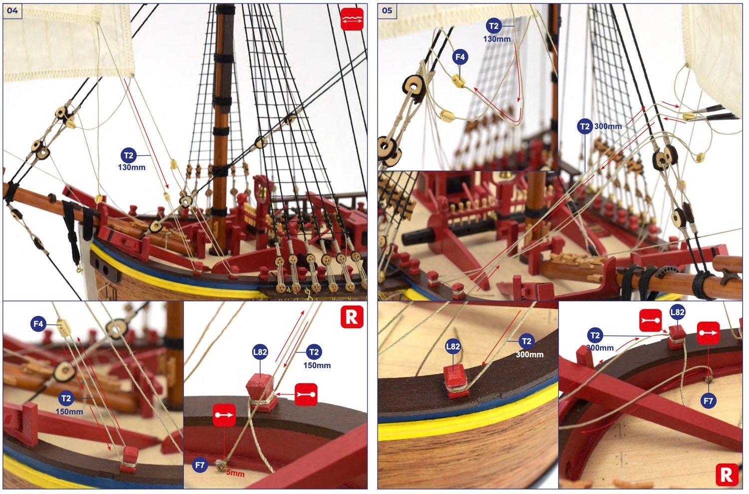
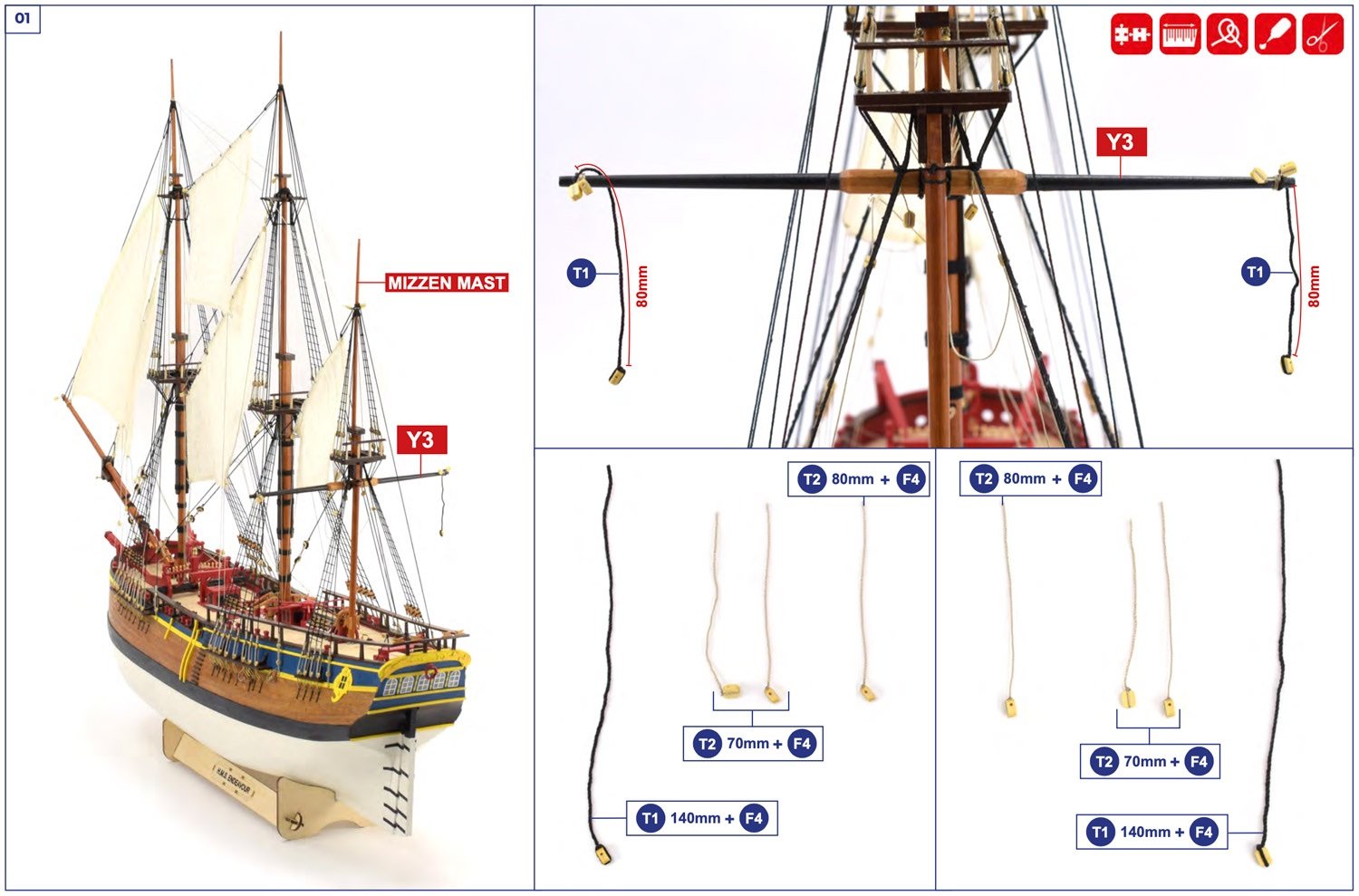
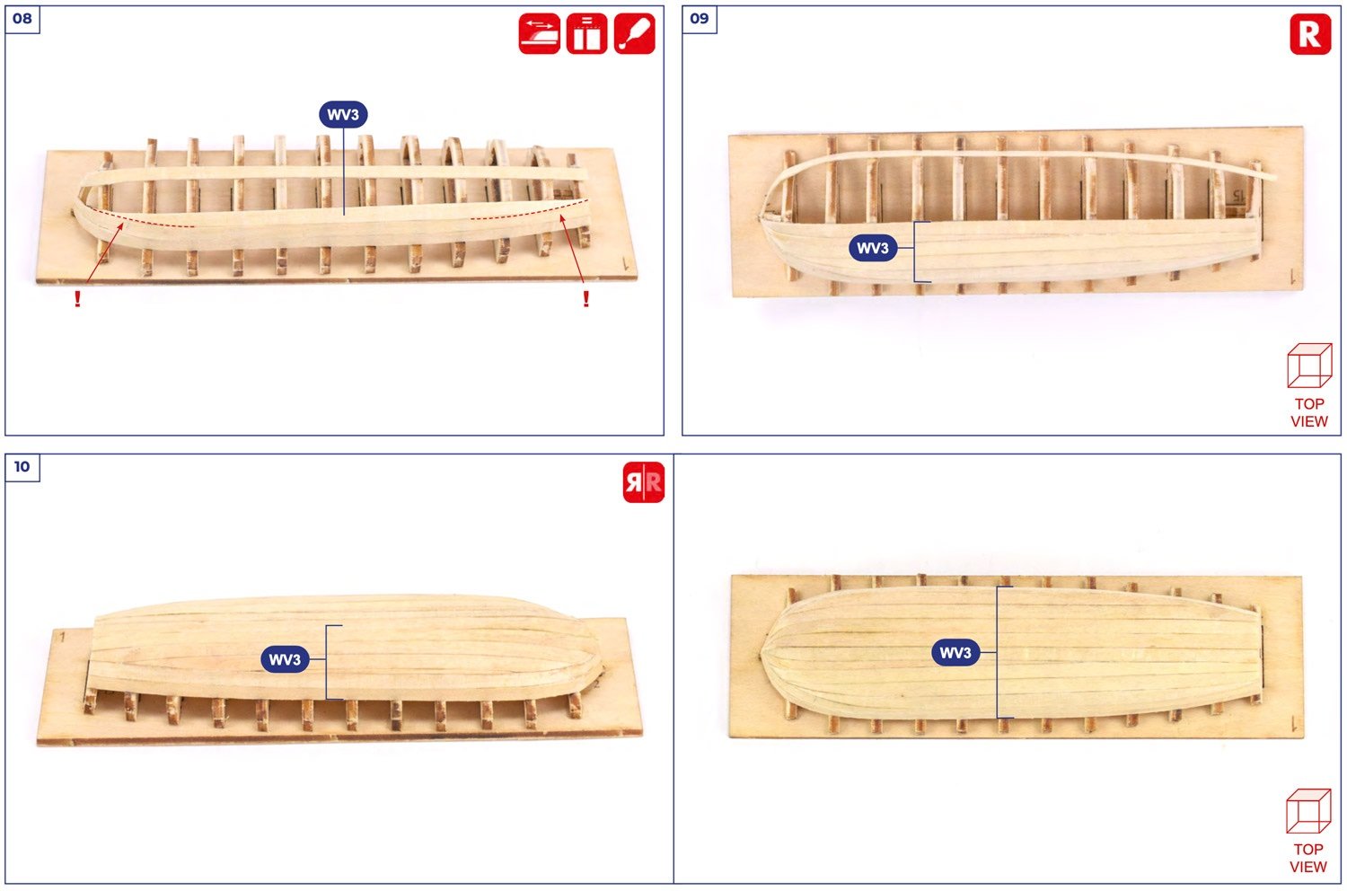
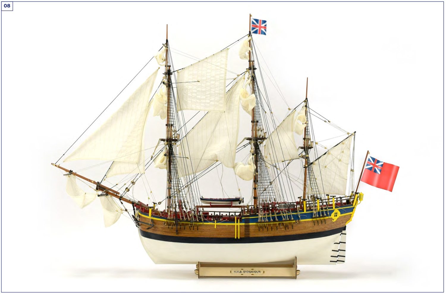
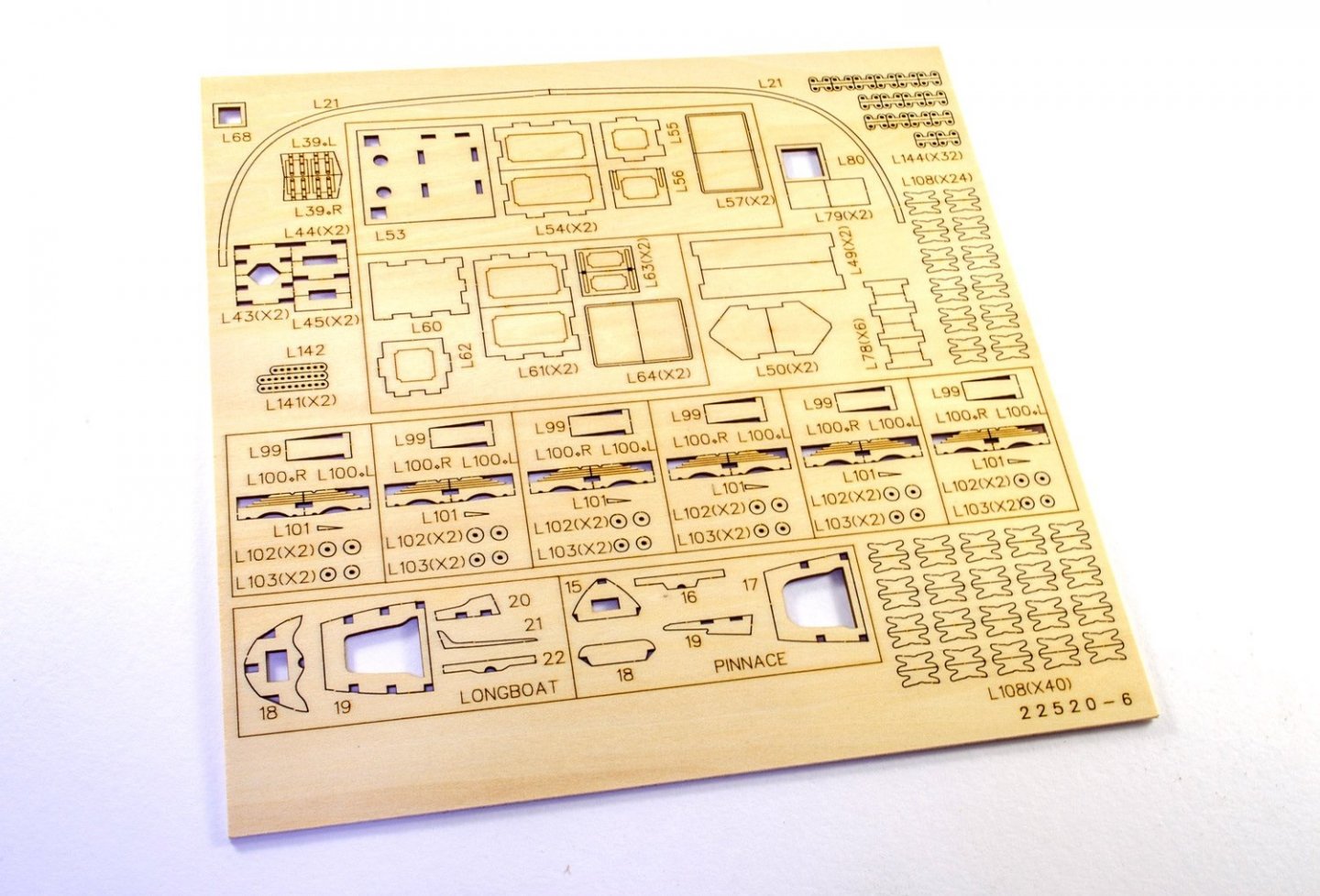
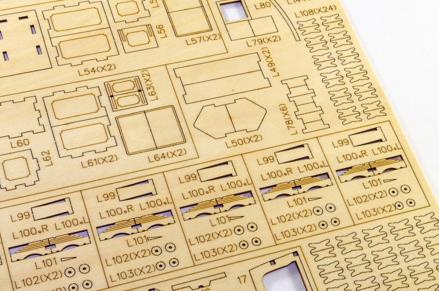
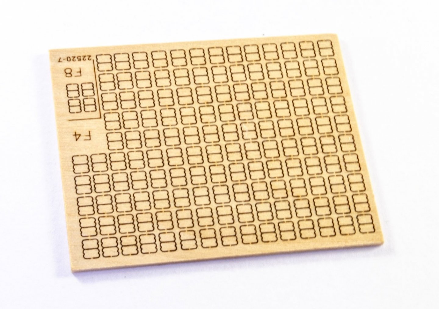
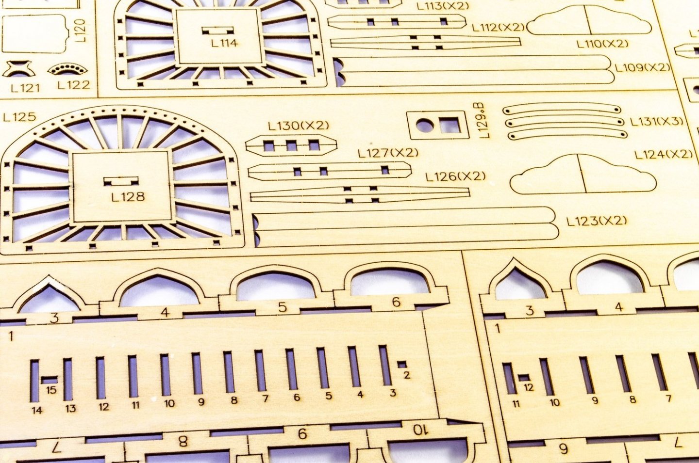
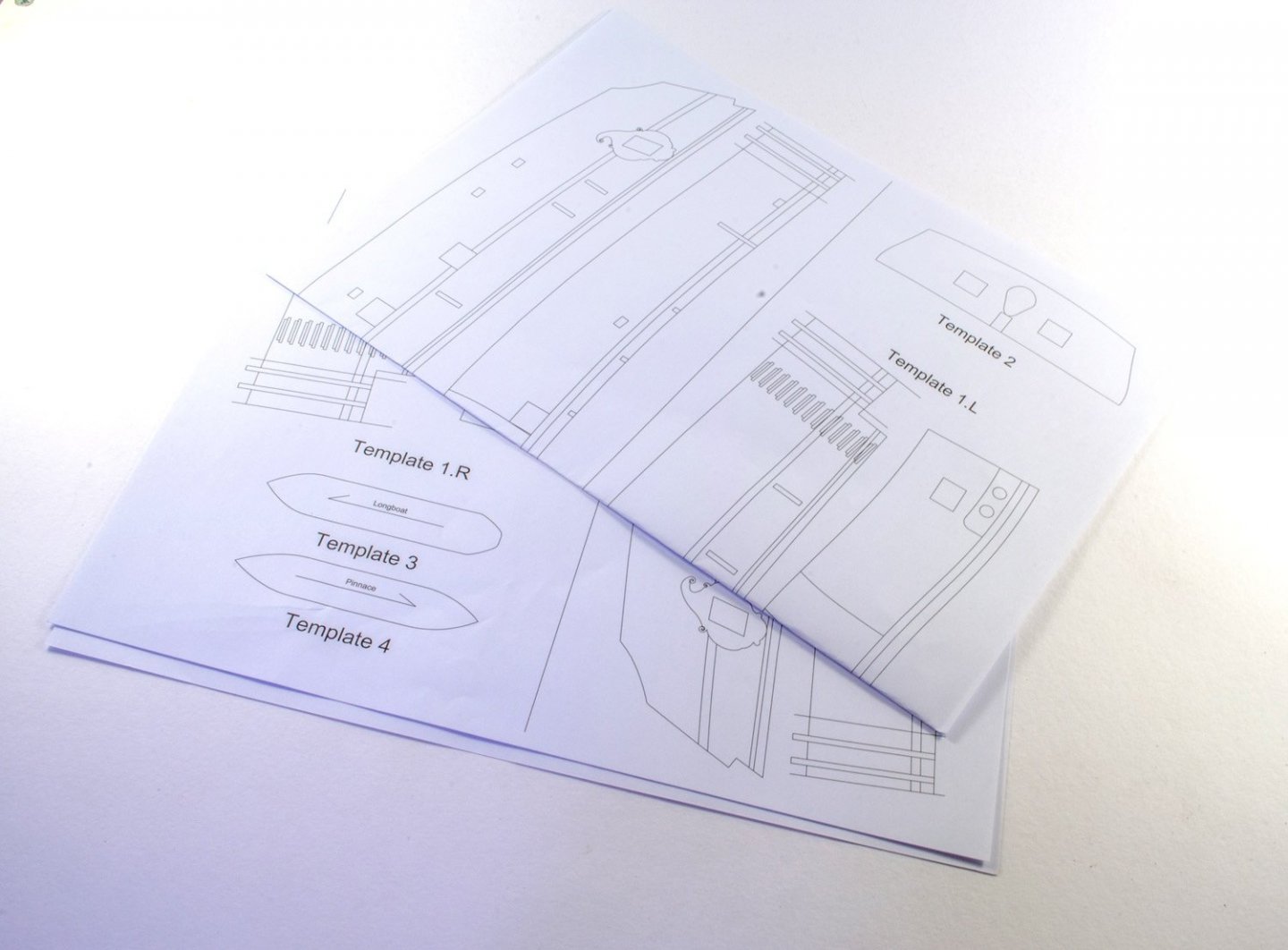
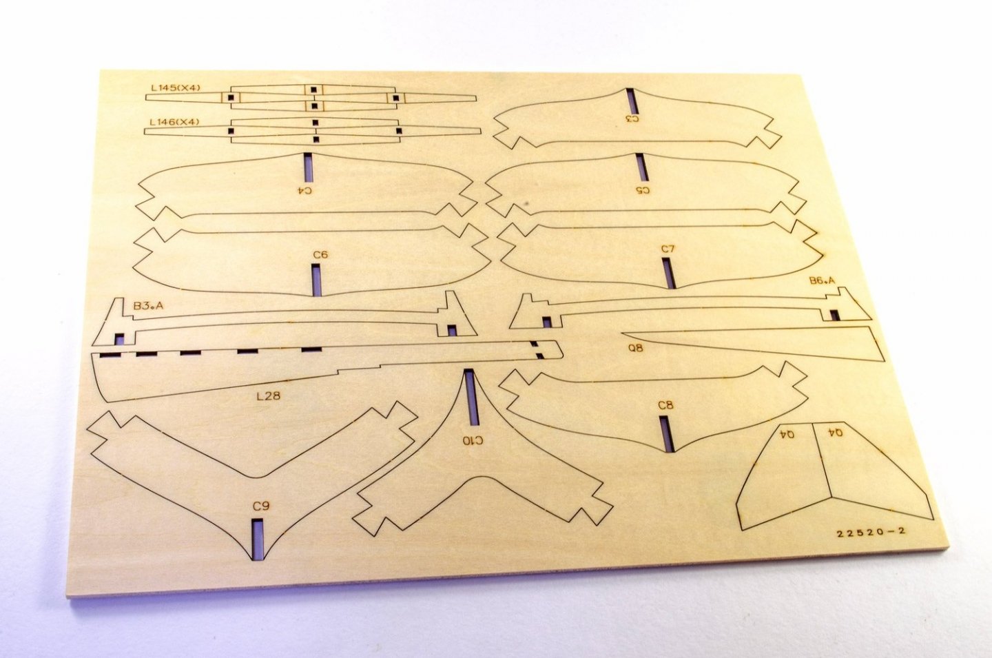
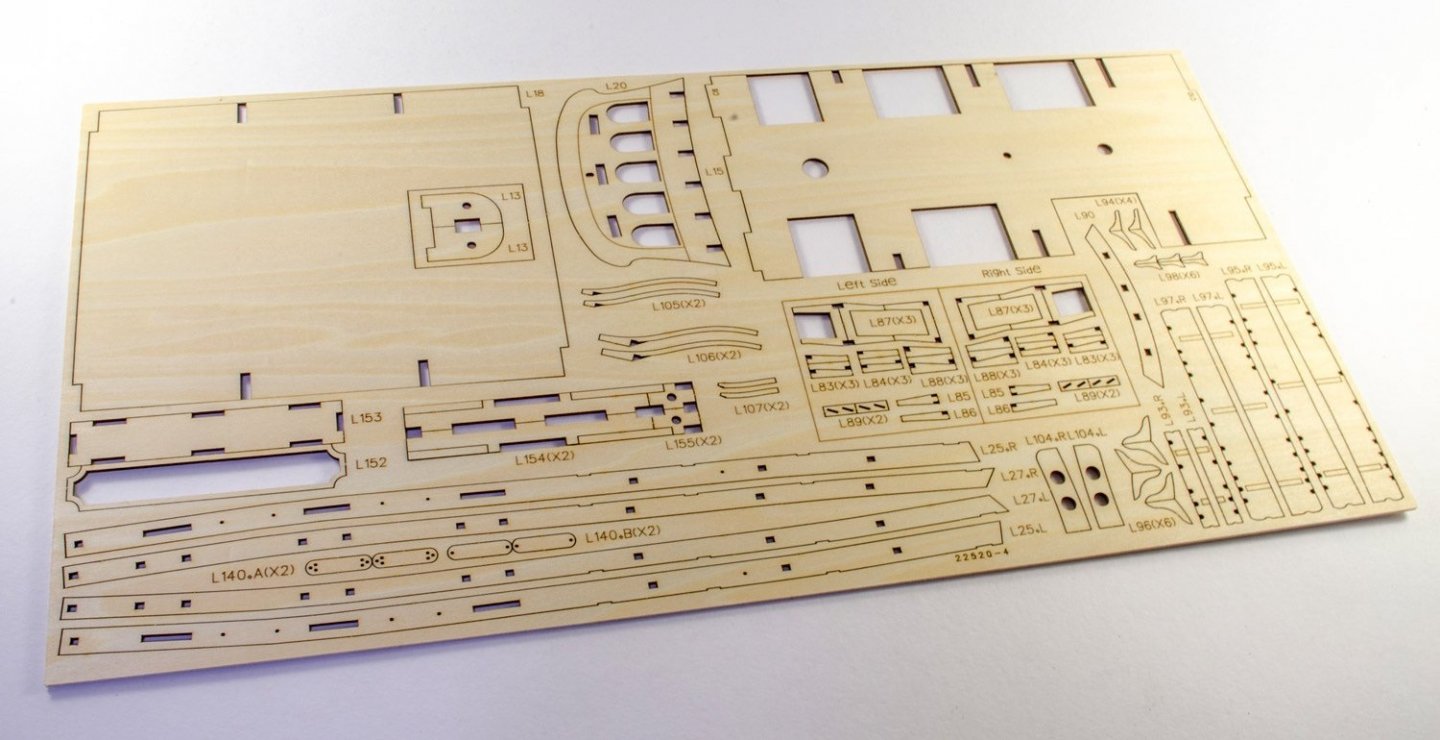
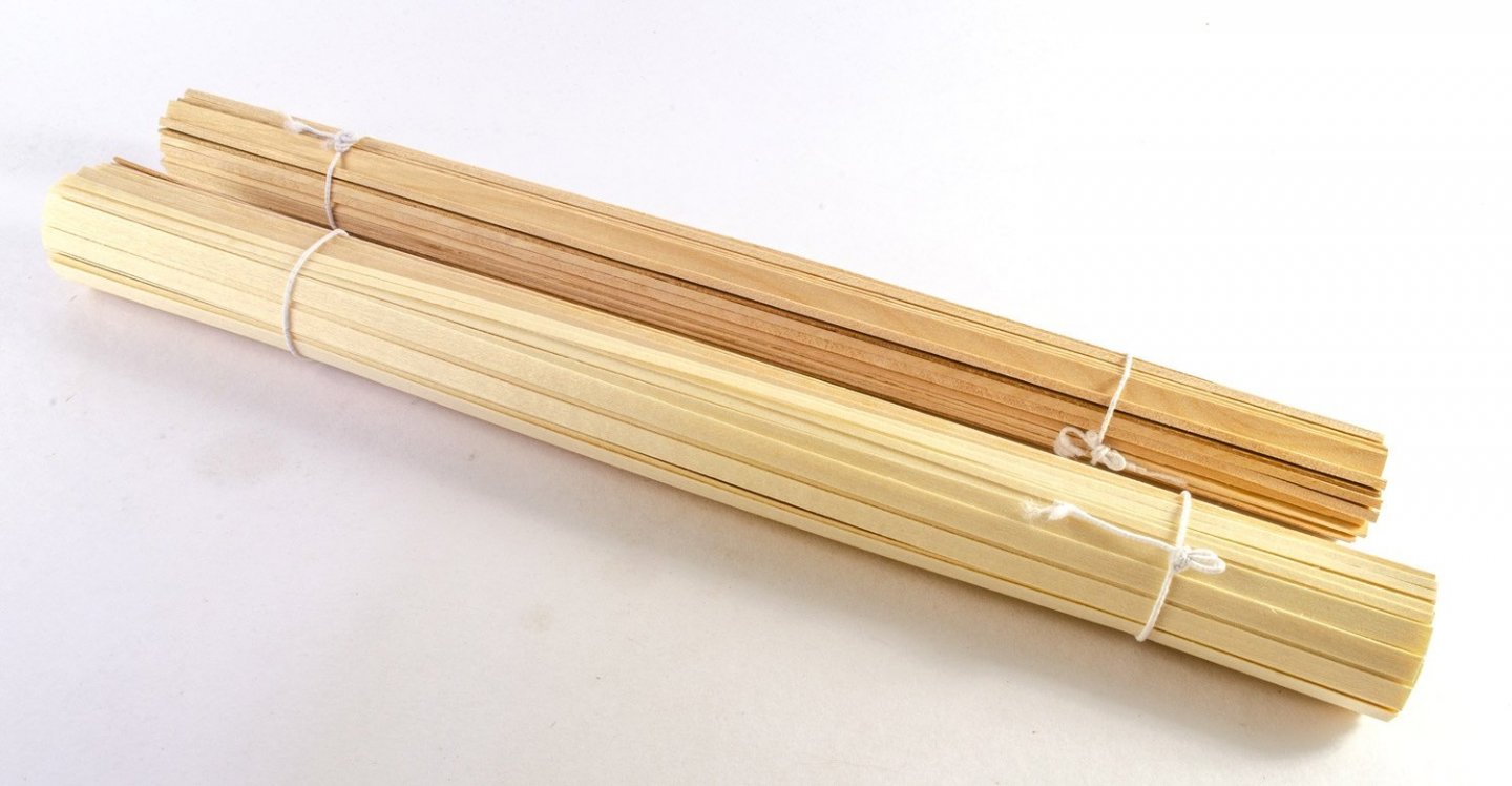
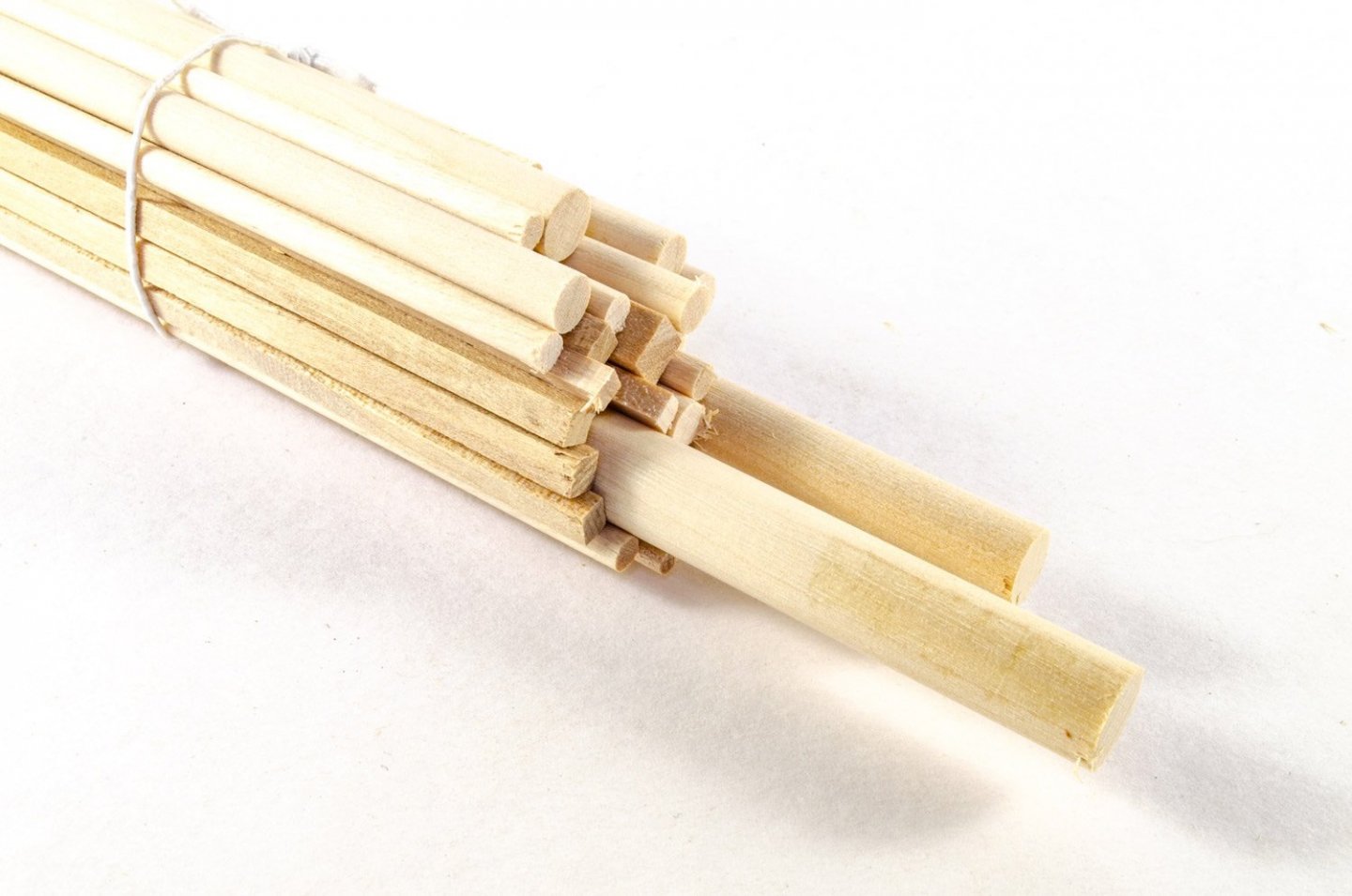
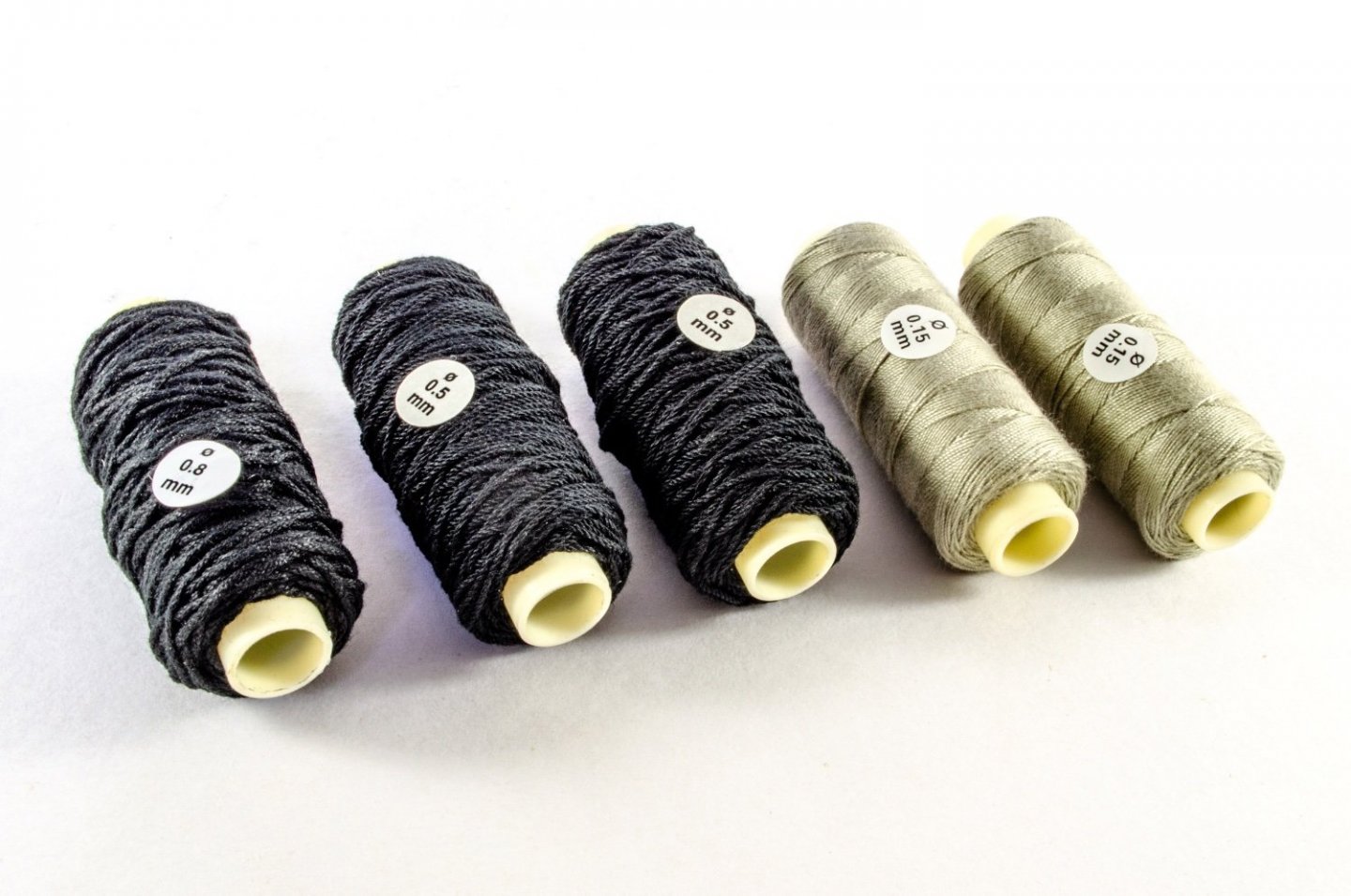
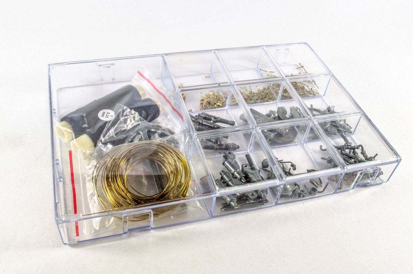
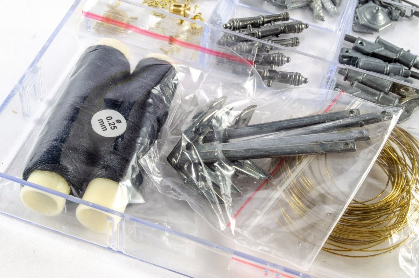
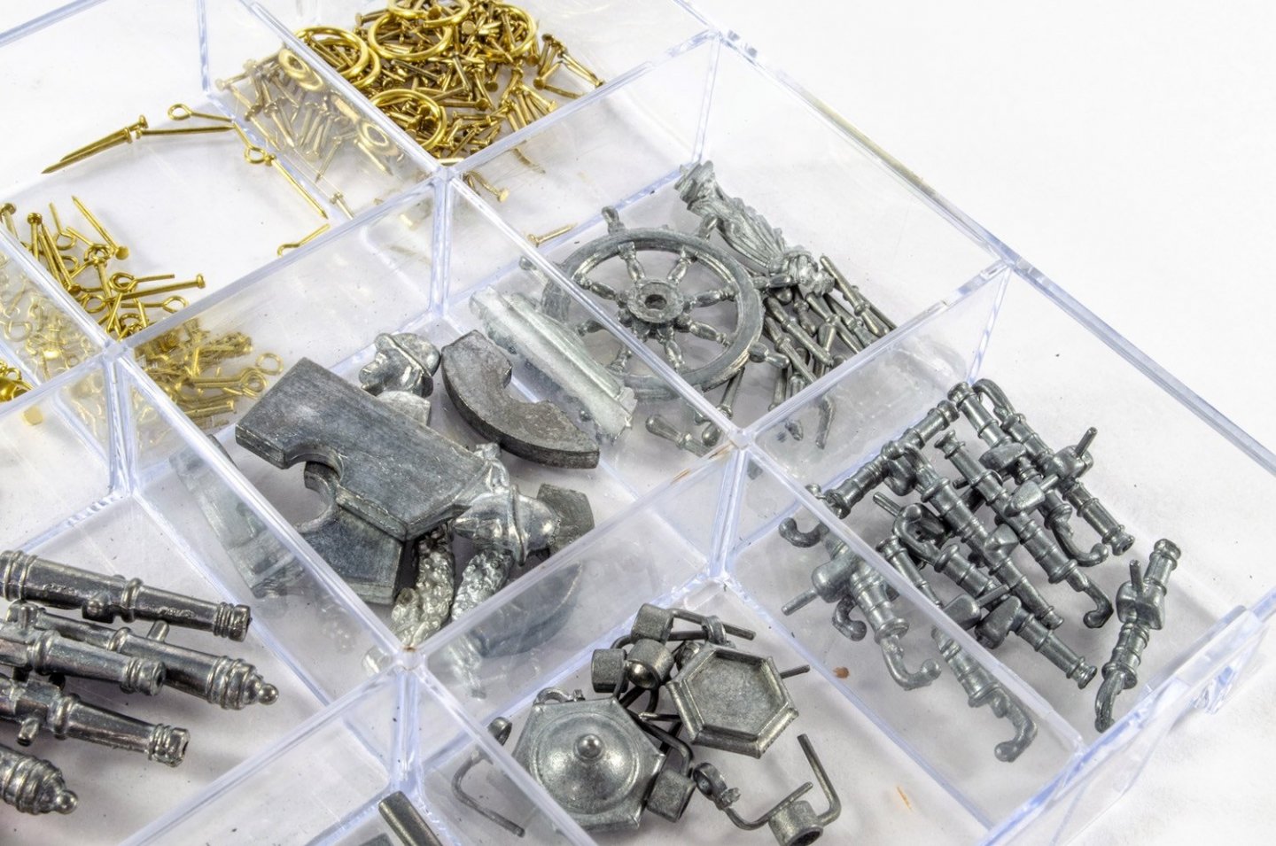
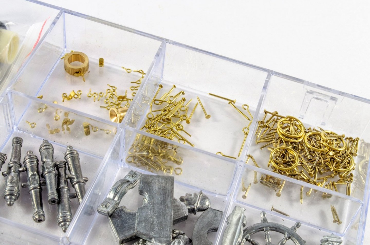
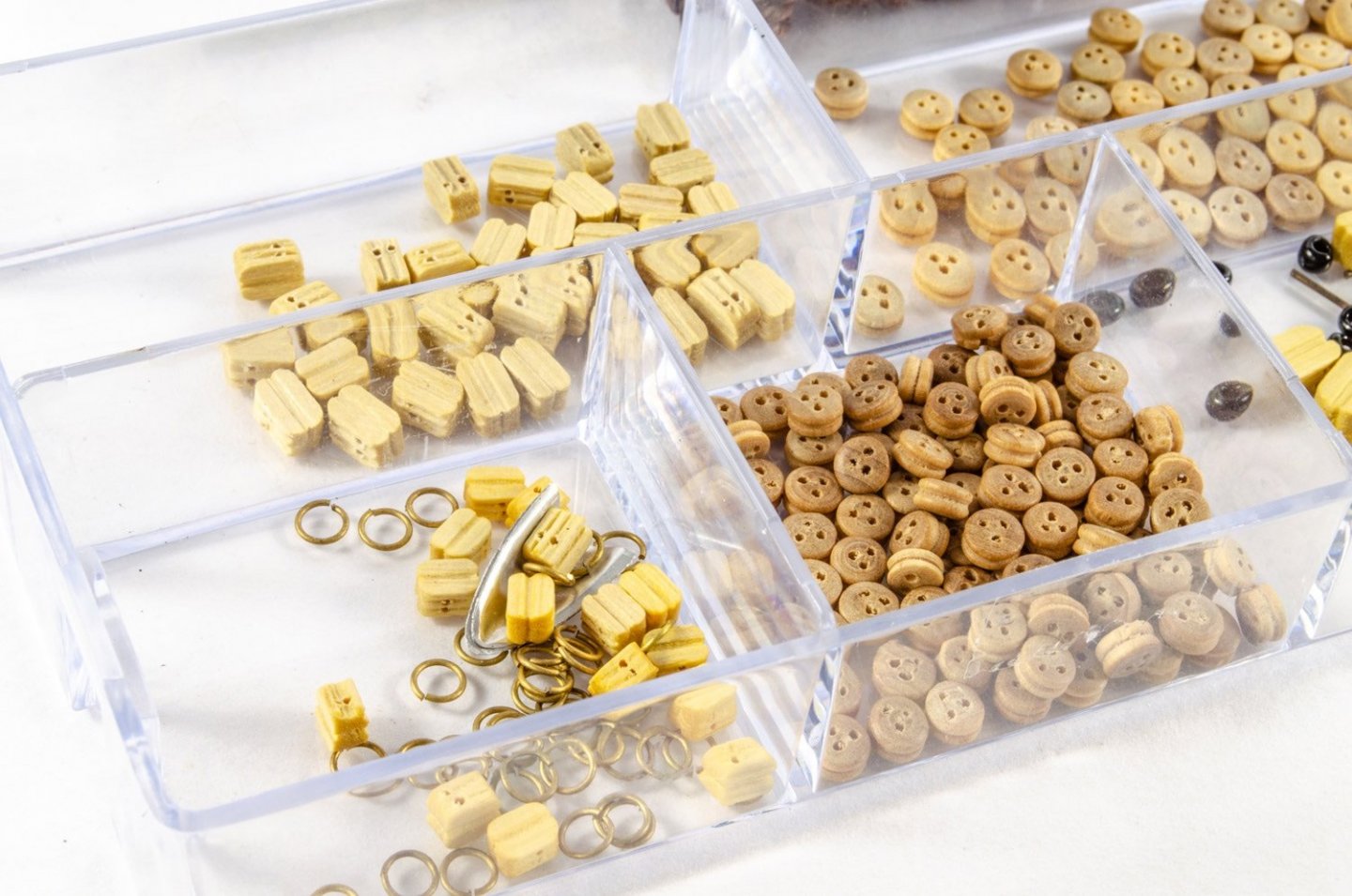
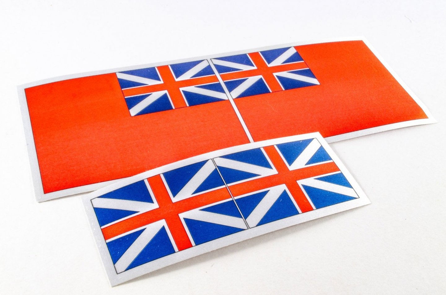
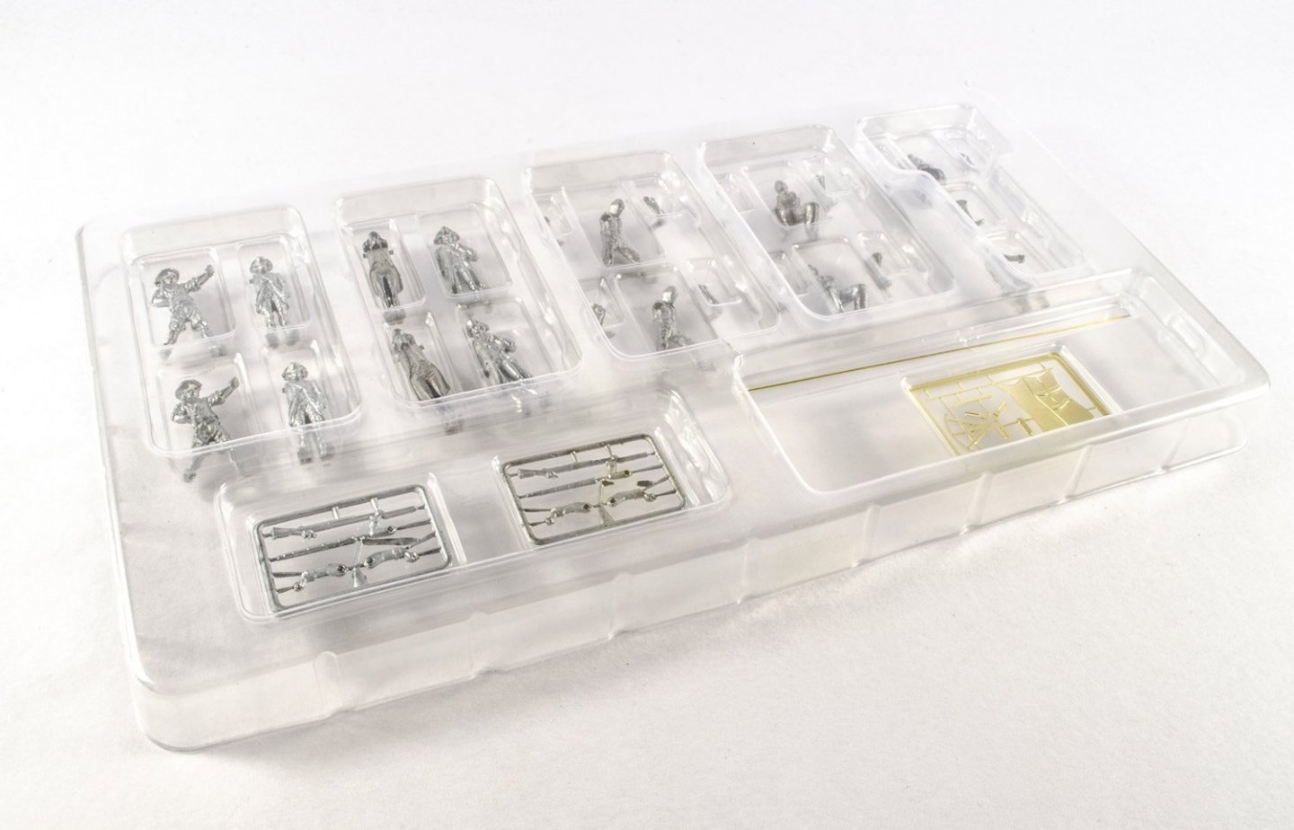
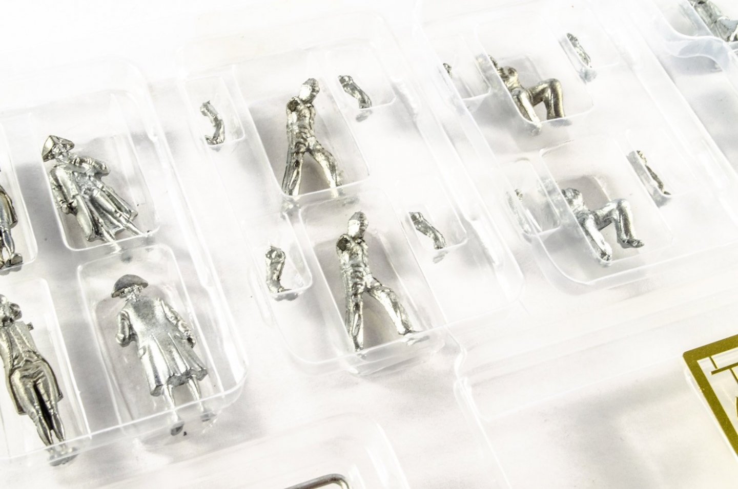
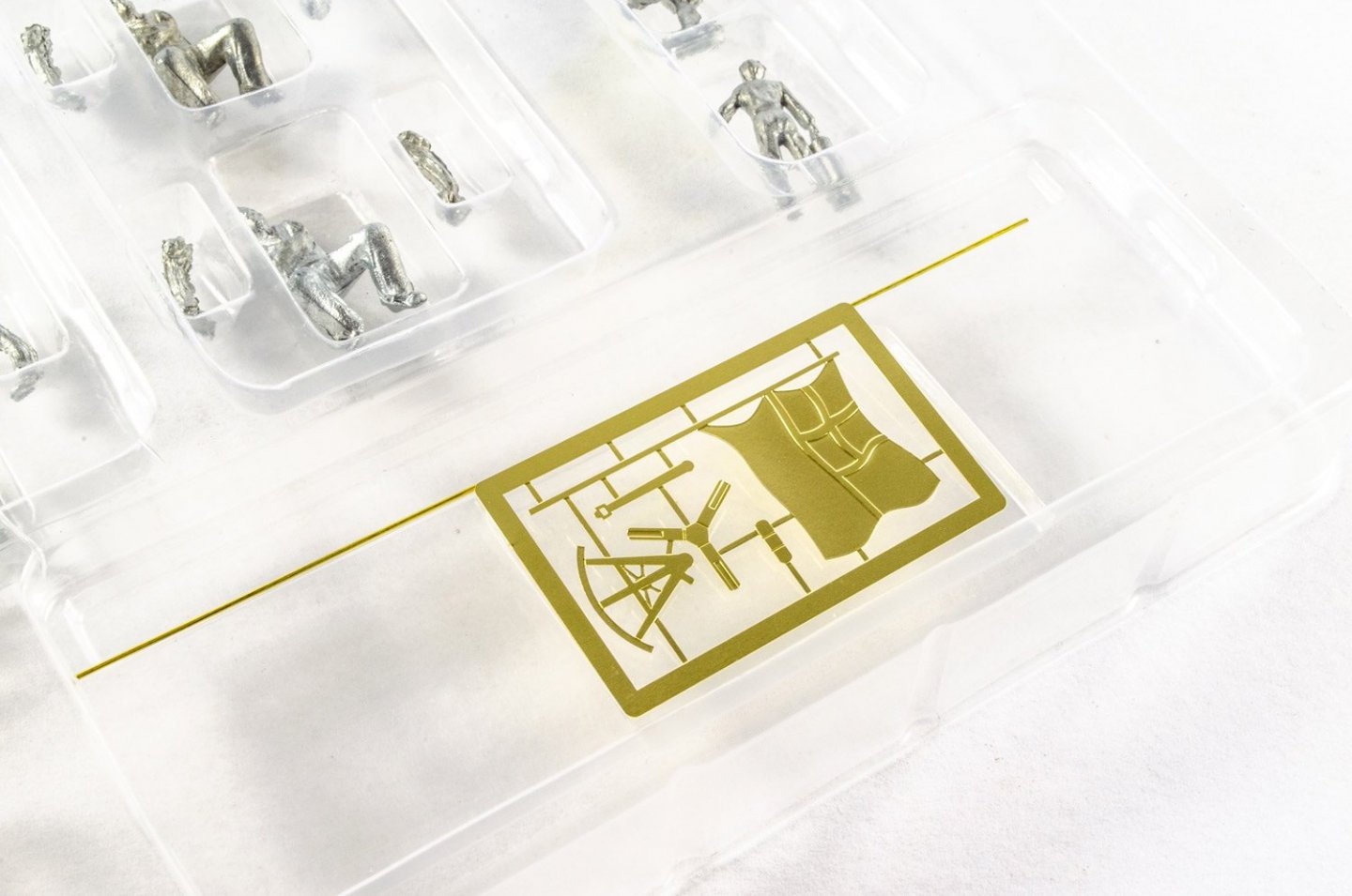
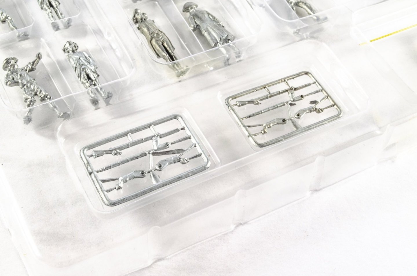
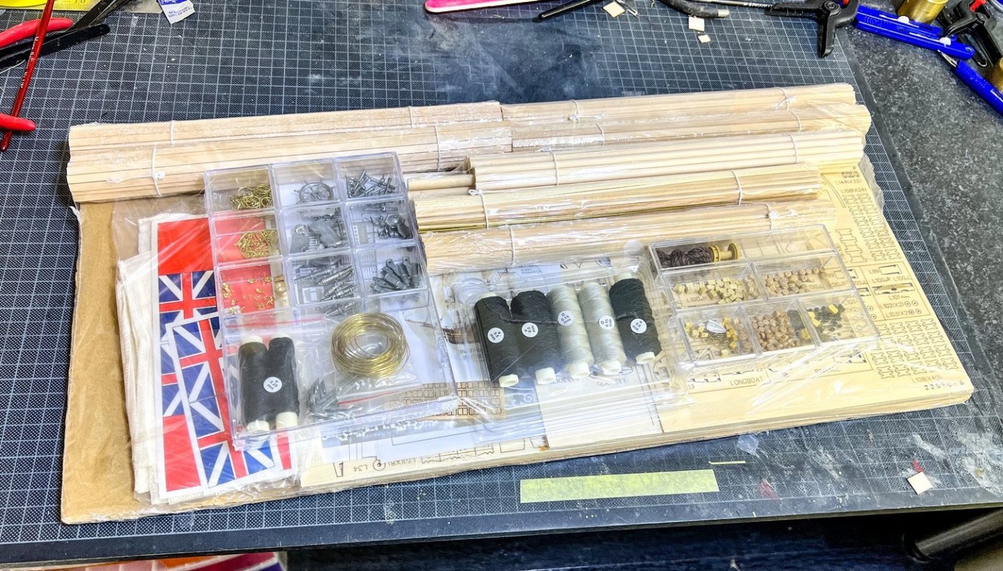
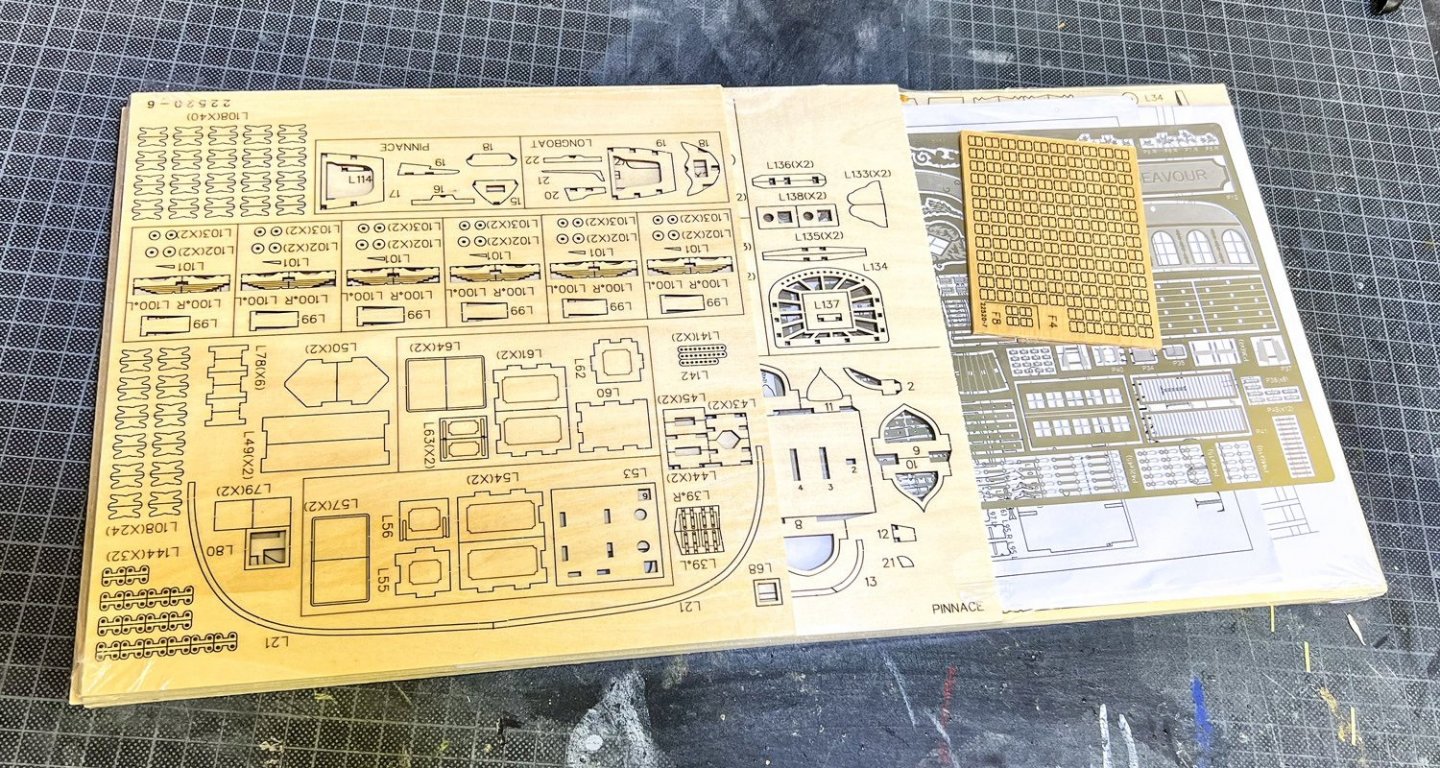
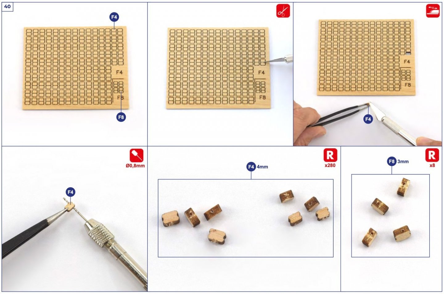
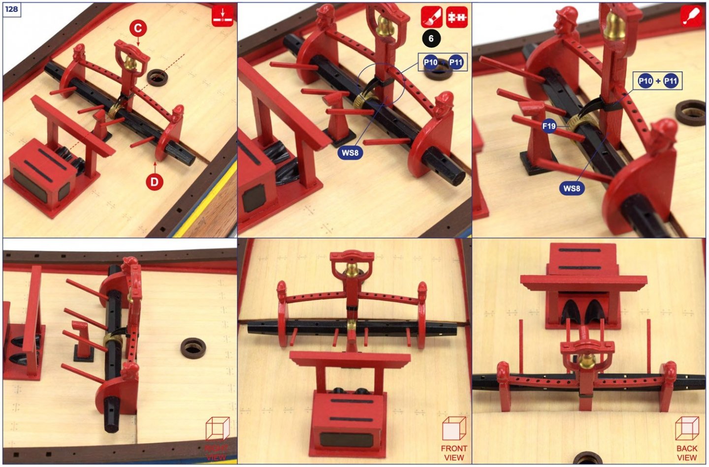
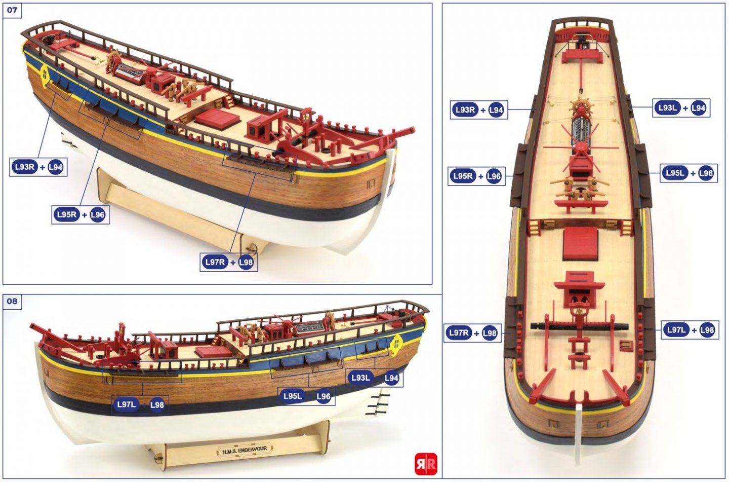
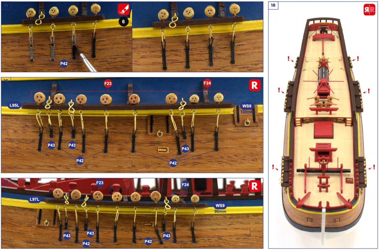
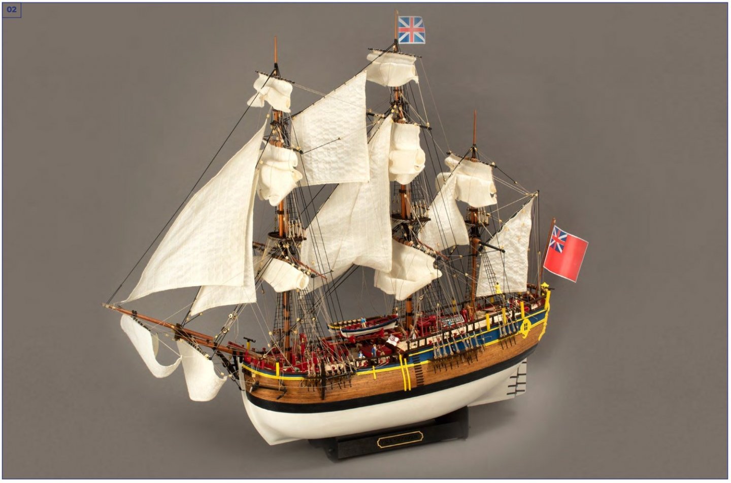
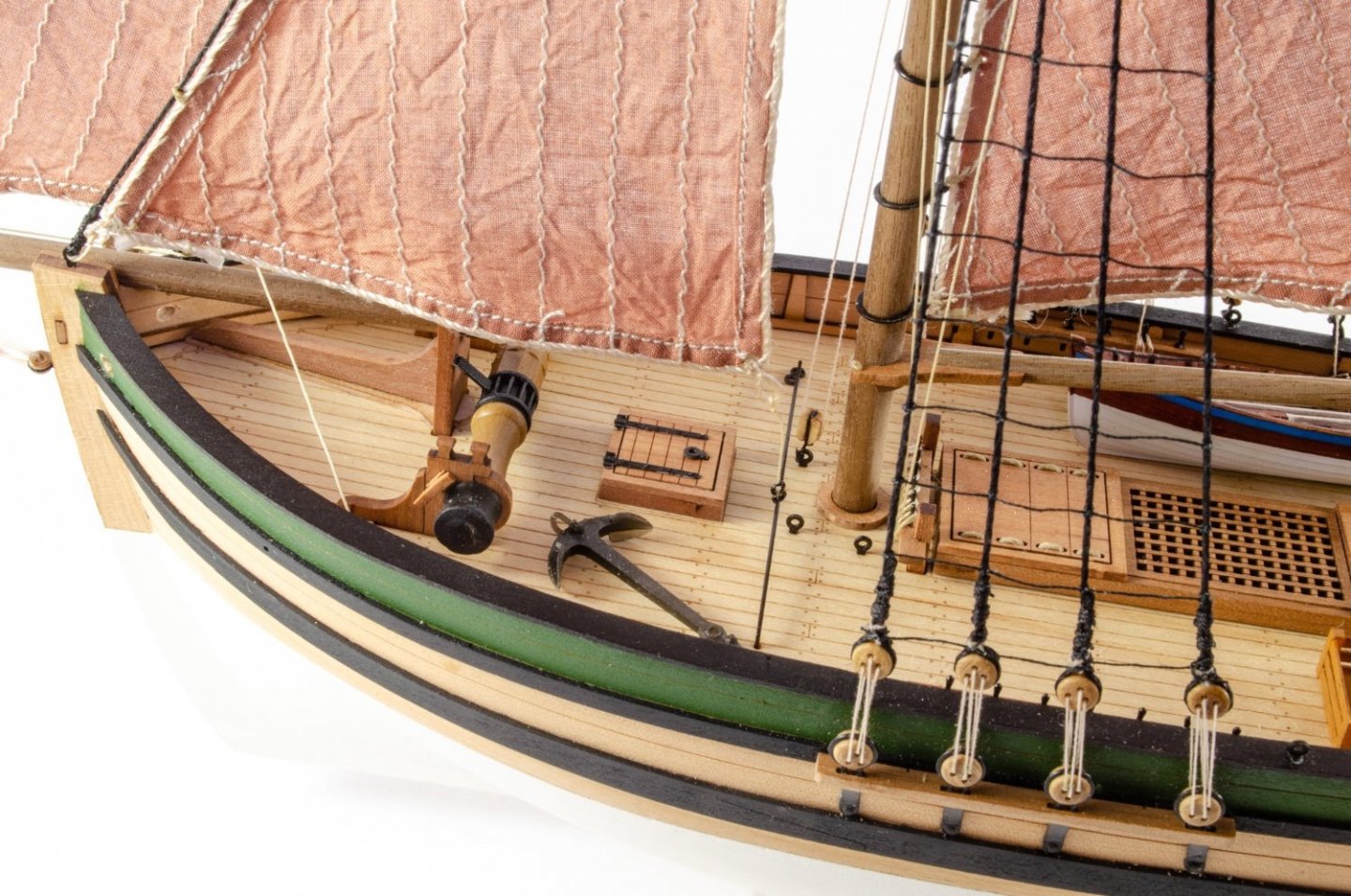
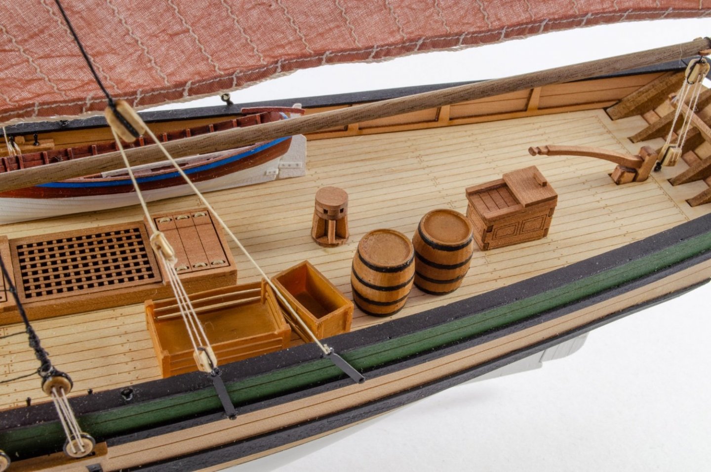
1:65 HMS Endeavour Artesania Latina Catalogue # 22520 Available from Artesania Latina for €231.40 History HMS Endeavour was a British Royal Navy research vessel that Lieutenant James Cook commanded to Australia and New Zealand on his first voyage of discovery from 1768 to 1771. She was launched in 1764 as the collier Earl of Pembroke, with the Navy purchasing her in 1768 for a scientific mission to the Pacific Ocean and to explore the seas for the surmised Terra Australis Incognita or "unknown southern land". Commissioned as His Majesty's Bark Endeavour, she departed Plymouth in August 1768, rounded Cape Horn and reached Tahiti in time to observe the 1769 transit of Venus across the Sun. She then set sail into the largely uncharted ocean to the south, stopping at the islands of Huahine, Bora Bora, and Raiatea west of Tahiti to allow Cook to claim them for Great Britain. In September 1769, she anchored off New Zealand, becoming the first European vessel to reach the islands since Abel Tasman's Heemskerck 127 years earlier. In April 1770, Endeavour became the first European ship to reach the east coast of Australia, with Cook going ashore at what is now known as Botany Bay. Endeavour then sailed north along the Australian coast. The ship was largely forgotten after her Pacific voyage, spending the next three years hauling troops and cargo to and from the Falkland Islands. She was renamed in 1775 after being sold into private hands and used to transport timber from the Baltic. Rehired as a British troop transport during the American War of Independence, she was finally scuttled in a blockade of Narragansett Bay, Rhode Island in 1778. Relics from Endeavour are displayed at maritime museums worldwide, including an anchor and six of her cannon. A replica of Endeavour was launched in 1994 and is berthed alongside the Australian National Maritime Museum in Sydney Harbour. The NASA Space Shuttle Endeavour was named after this ship, as was the command module of Apollo 15, which took a small piece of wood from Cook's ship into space, and the SpaceX Crew Dragon capsule C206 was christened Endeavour during Demo-2. Abridged extract from Wikipedia The kit Firstly, this kit bears no relation to the Endeavour kit of years gone by. This is a totally new development in that the construction is entirely different….different parts, methodology etc. Artesania, simply put, are not the same company from those years ago, but the new owners have taken on a lot of the old inventory while also developing entirely new releases, such as Endeavour, Vasa, and Soleil Royale etc. The Endeavour kit that is available today should not be viewed with a connection to the past. Artesania Latina has designed this new kit using the research available to them, and by studying the full-size replica which resides in Australia. They have also incorporated into it the ability to fit it out with their LED lantern set, by means of adding the various holes needed to thread cables. That set is a separate purchase to the kit, but we have it here and will show it as a separate article. The one thing which does have the original Artesania feel to it is the glossy, tough box that these kits are still packaged in. Artesania’s on-shelf presentation is as nice as it ever was. Inside the box, all parts are initially bundled within a large, cellophane wrapping. Remove this and you’ll find the timber and metal parts are within another wrap, and all of the timber strip bundles are also wrapped, as well as held together with an elastic wrap, which I quite like. Note that the planks are supplied as half-lengths, so not full bow to stern. Also there are the familiar Artesania Latina clear plastic fittings boxes. These are just a few on-bench images before I opened things up properly. Timber strip Artesania's timber strips are definitely of a nice quality, being consistent in thickness and width. As I've stated, the hull planking is supplied as halves. My measurements show this to be 2mm x 5mm x 300mm lime strip. That's quite thick stuff to get around that very bluff hull, so I suggest you soak these beforehand, or use another tool such as a plank nipper to manipulate the material. Plenty of material is supplied for this. In fact, four whole bundles. There's no apparent stringiness or rough surface. This is just as well as Endeavour is SINGLE PLANKED! In a world where POF tend to be double planked, Artesania has bucked the trend with this. The 2mm wood should give the modeller plenty of leeway when it comes to sanding things, but getting the hull fairing right is very important. I also have to say at this point that the only part of the hull in which actual timber will be shown is a band around the width, the wale, which is given another layer of 0.5mm x 5mm strip unidentified timber. The rest of the hull above and below this is entirely painted. The quality of the remaining timber strip and dowel are as good as the lime, with no splitting, fraying, rough cut edges or any other defect. Wooden parts EIGHT sheets of plywood parts are supplied with Endeavour, in various thicknesses. All parts are cleanly laser cut and the material in my sample has no warping. I know some of the older AL kits had a strange spongy core to their ply, but this appears to be replaced with good quality ply in the new kits. One thing I did notice is that the single-hole rigging blocks are supplied as laser cut parts, for some reason, and you need to drill your hole in them. Not too keen on that idea. Here's the parts to show you the standard to expect in Endeavour: These are single-hole rigging blocks (above) There are a few things of particular note here. The bulkheads are not as you would normally see. These are made up from several parts which create what is more of a frame than a bulkhead. The parts also are joined by a dovetail. The stand is actually designed to accommodate, should you wish, an LED illumination module. AL have sent us one of these and I'll shortly post a review. All external keel parts are also in ply instead of solid timber, presumably because they completely painted. Two ship's boats are included, built up from frames that sit on a jig. All parts are also laser etched with numbers, and a parts plan is also included in paper form. Photo Etch This single sheet of photo etch appears to be a stainless finish, or at least not nickel plated, to my eyes. The quality is pretty much what you'd expect from a contemporary manufacturer, in that the etchings are clean, detailed and the connection tabs are slight so should be easy to cut through. Just remember that any PE part will need the connection nub filing down before fitting. You are also advised to use a decent quality etching primer so your paint can get a proper grip. On here you will see parts for the stern, chainplates, windlass etc. Fittings Two trays of fittings are supplied. The larger one contains some 0.25 rigging rope, brass wire, cannon, swivel guns, cast anchors, eyelets, pins and various other cast metal parts. The smaller box contains hawse cable, turned wooden capstan, deadeyes, larger rigging blocks, metal tube, eyelets, parral beads etc. Flags Endeavour also comes with some flags. These are a sort of plasticised material. You may want to source something a little thinner for your model. Rigging Cord A further pack of rigging cord is supplied in a clear blister pack, in black and natural. Sizes can be seen in this photo. Sails I've never been a fan of fitting sails to ships, but in case you wish to, then AL have supplied a full set for you which are nicely sewn from a material which is off-white in colour. There are no bolt ropes on these, so you may want to sew your own onto them. Templates Two sheets of paper templates are included. These are to lie onto the completed hull in order to provide locations for cutouts and other details such as wales etc. Instructions As mentioned in our Santa Maria build, AL kits do not come with any printed instructions or plans. The latter, quite frankly, isn’t needed due to the sheer depth of information in the electronic instructions. The manual comes on a DVD and is over FIVE-HUNDRED pages long! That would of course pose a logistical problem and extra cost for Artesania to include. It also poses a logistical problem for the modeller who will need the means to read the electronic manual at their workbench. Some computers, like my MacBook, don’t have a DVD drive. In instances like that, you can always go to the Artesania site and download the entire manual and save to either your internal drive or to a USB pen drive. Artesania’s instructions are very much full-on, in that nothing is left to the imagination. Every single stage is clearly illustrated and annotated with clear part numbers and symbols to declare whether something needs gluing or not. If you want to see the whole manual, click HERE. Here’s a few images from the manual, just to give you an idea: Conclusion Artsania's new Endeavour kit is most definitely a different beast from the original one from many years ago, and AL obviously aren't too worried about mixing things up a little and incorporating ideas from contemporary kit designs. I would definitely not recommend this kit for a beginner, simply because of the single-planked hull. I would like to have seen that done from at least two 1mm layers, so care will be needed to make sure you prepare the hull before you start to lay any planks. There are some very nice touches, such as the windlass with its folded metal body and brass gearing. Another things I would change would be the laser-cut single rigging blocks. They really do need to be replaced with proper rigging blocks. Artesania still know hoe to play to their target market, as this kit clearly shows, and the introduction of these new designs to their range is very welcome. Other new designs are their Soleil Royale and Vasa, constructed in roughly the same manner. It's wonderful to see Artesania Latina back at being a player within our hobby. I cut my model shipwrighting teeth on AL kits, so have that fondness for them. My sincere thanks to Artesania Latina for the sample looked at here. To buy this kit, head off to the link at the top of this page, or contact your local hobby supplier for availability. ALSO available for this kit: HMS Endeavour figure set Available from Artesania Latina for €20.65 This is a set of 14 crew figures for Endeavour, comprising of crew, some with separate arms etc. and also some PE parts for ship navigation instruments and ensign. Note also the extra metal parts which contain more arm parts for holding the supplied rifles. Casting is nice for this scale, and colour notes are supplied on the reverse of packet.


-
Nice to see L'Hermione out again.
-
How many kits do you have on the go at the moment?
James H replied to CaptnBirdseye's topic in Wood ship model kits
Please remember that not everyone has the time, inclination or workshop space to produce the parts needed to scratch build. I know I don't. That's why I'm happy to work on quality kits. I sometimes feel that there are folks on MSW that look down both on kits, and those that build them.- 54 replies
-
- 18
-

-

-
Posting video
James H replied to Valkyrja68's topic in Using the MSW forum - **NO MODELING CONTENT IN THIS SUB-FORUM**
Personally, I prefer pictures. With a video, you have to take time to watch it instead of scrolling images. If I see a video log, I tend to ignore it. -
Will you be building this kit as a build log?
-
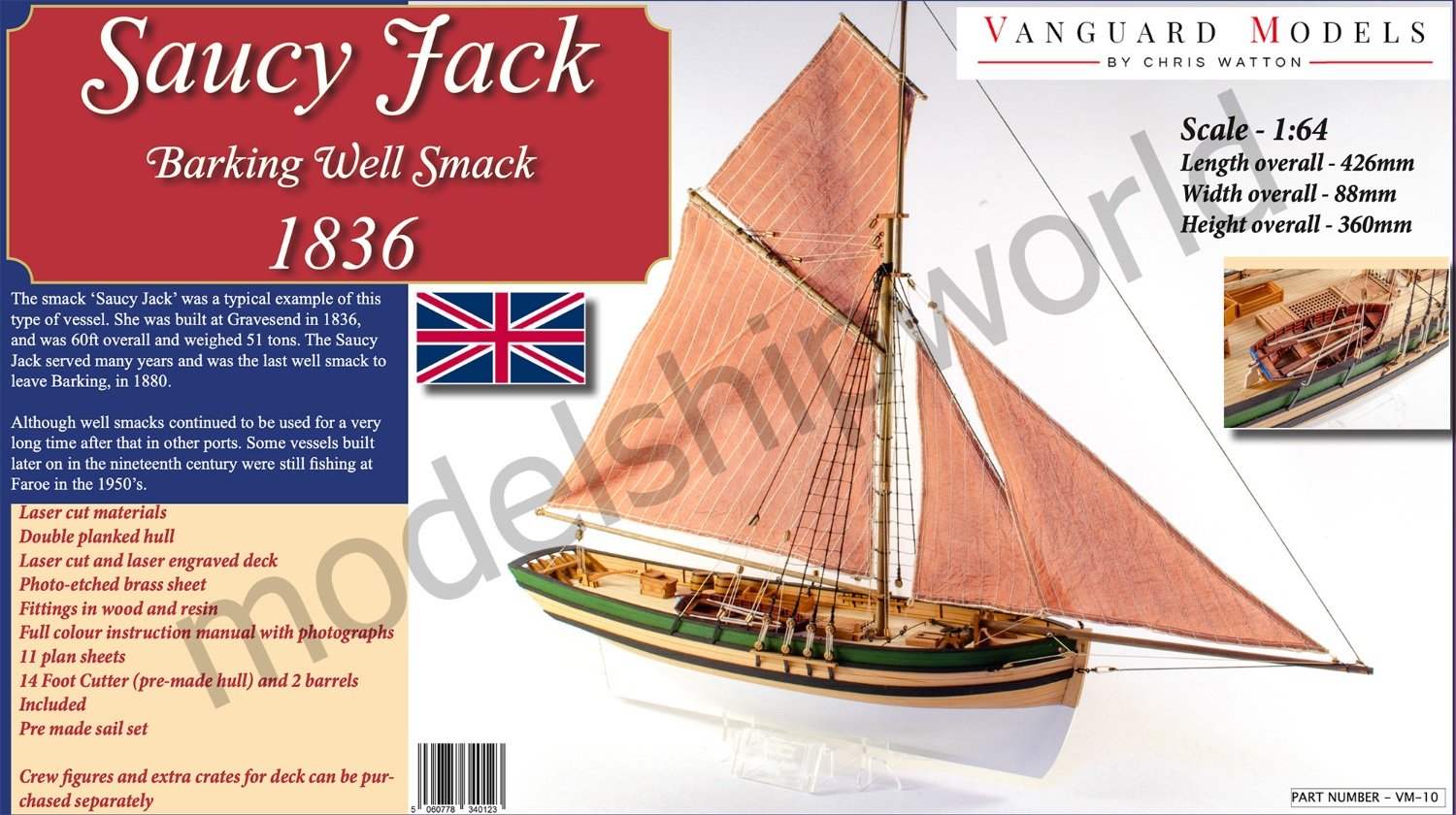
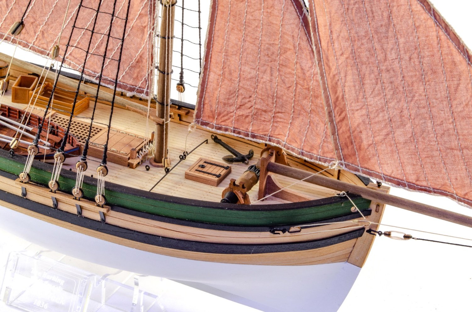
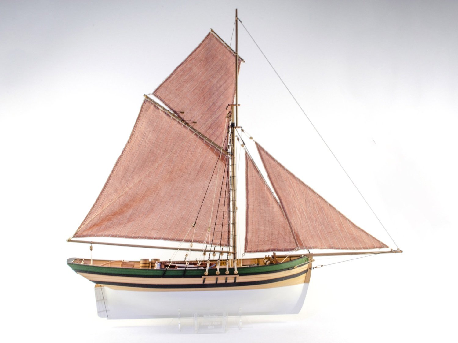
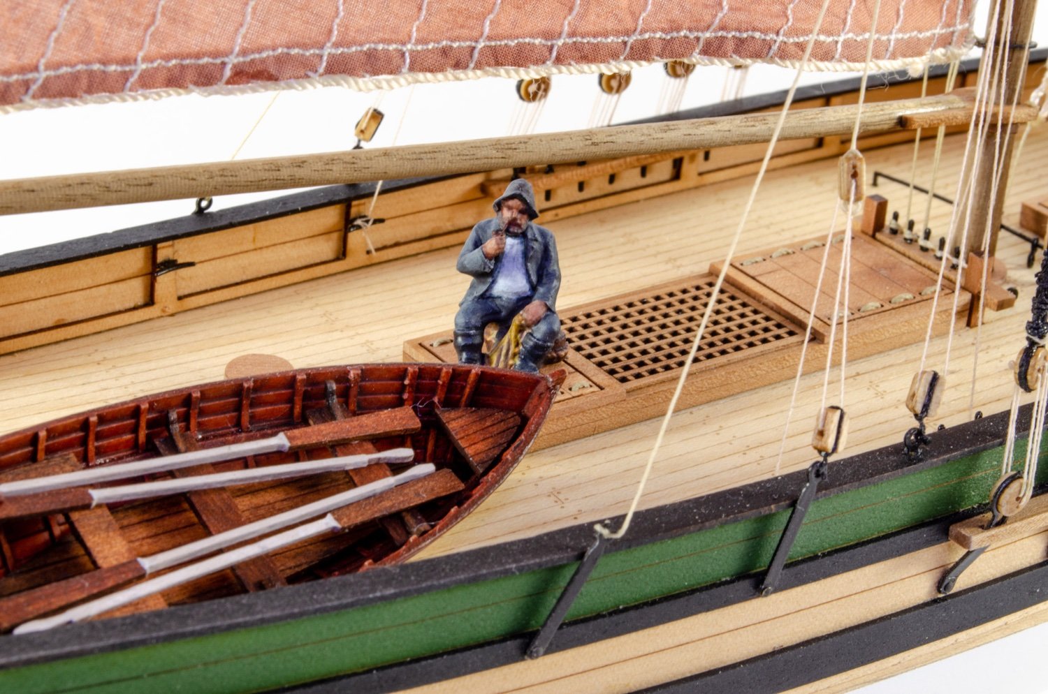
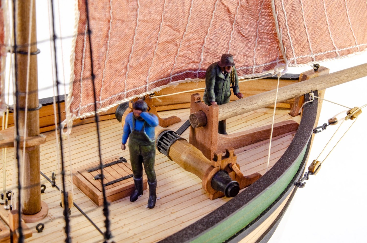
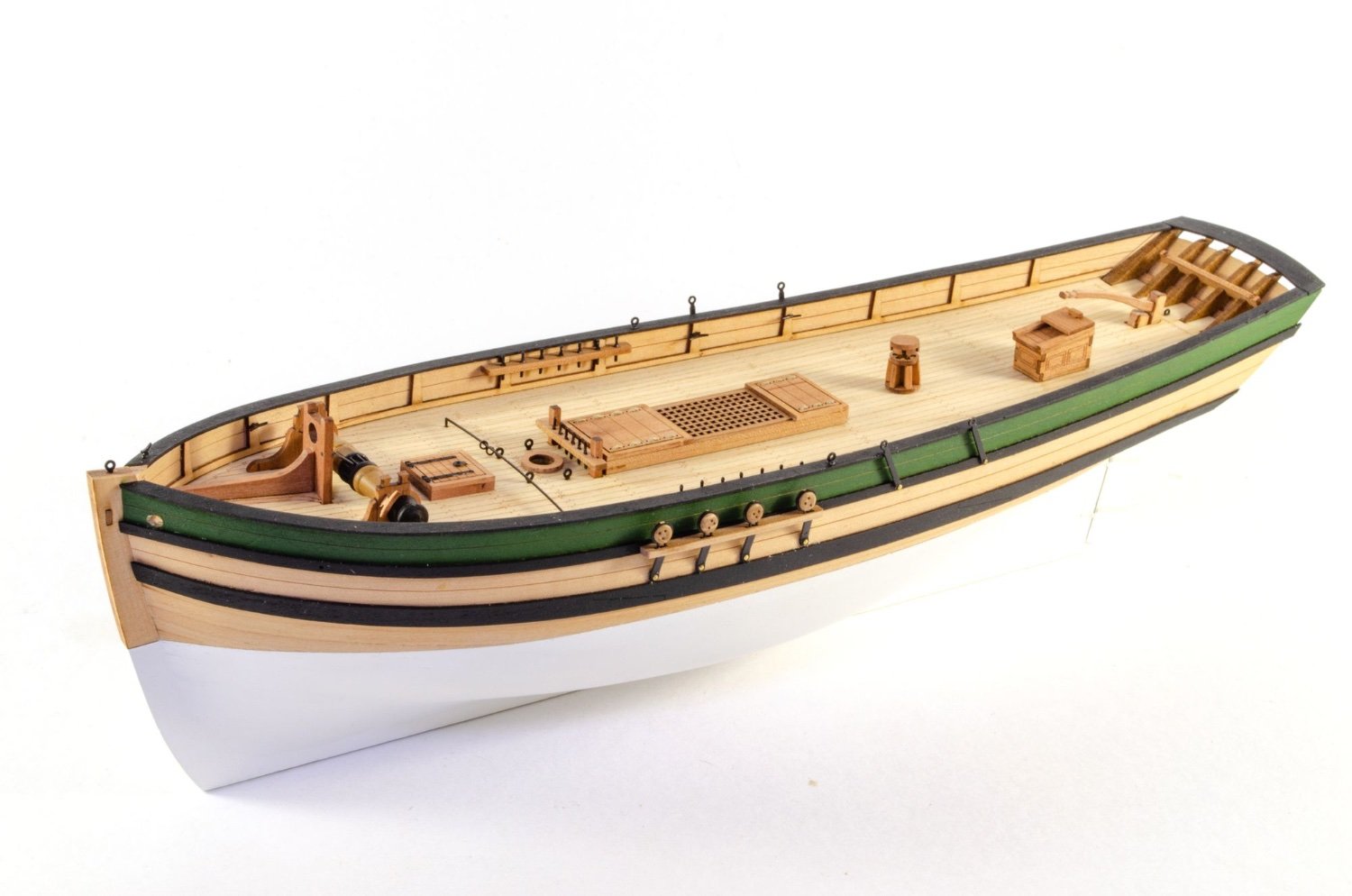
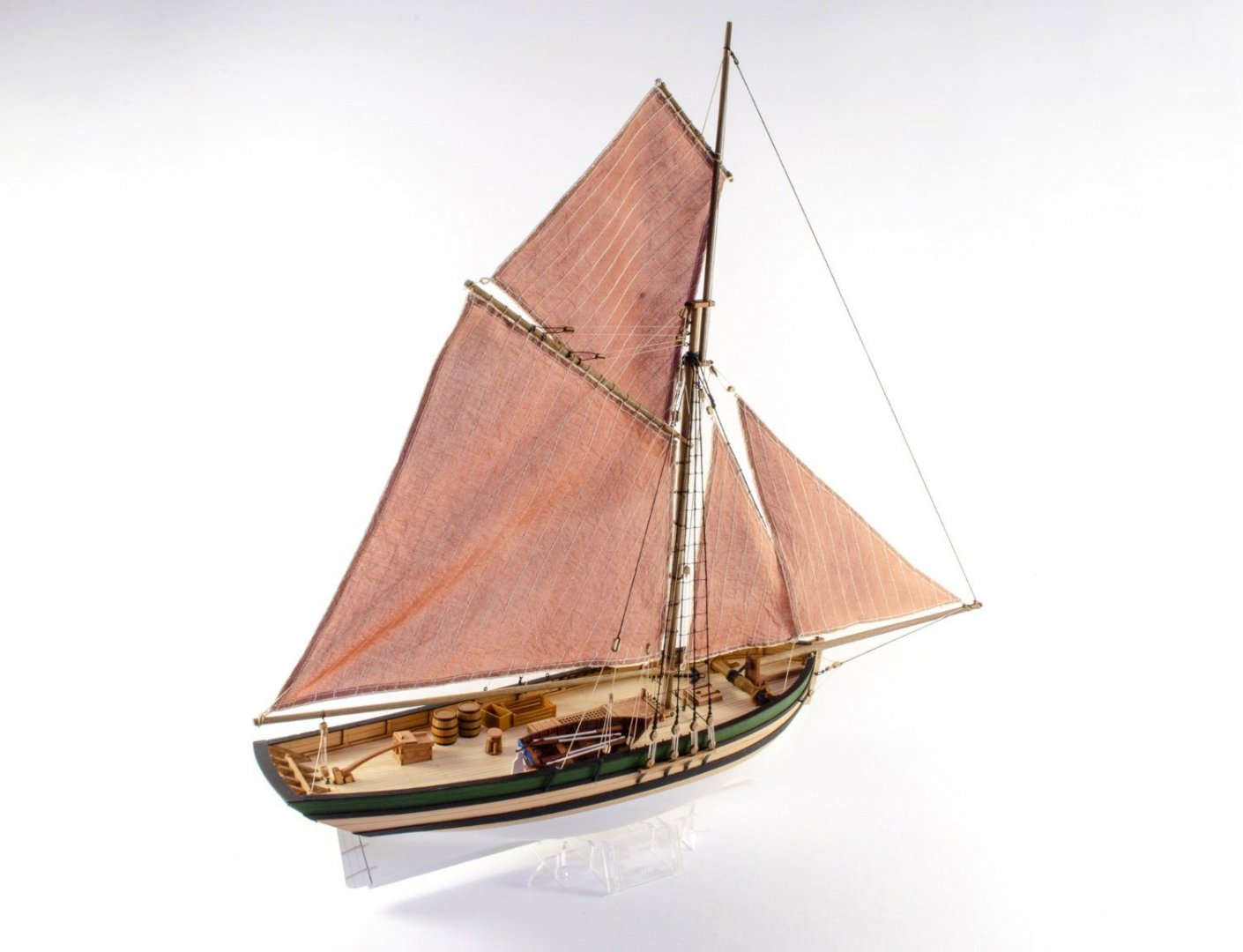
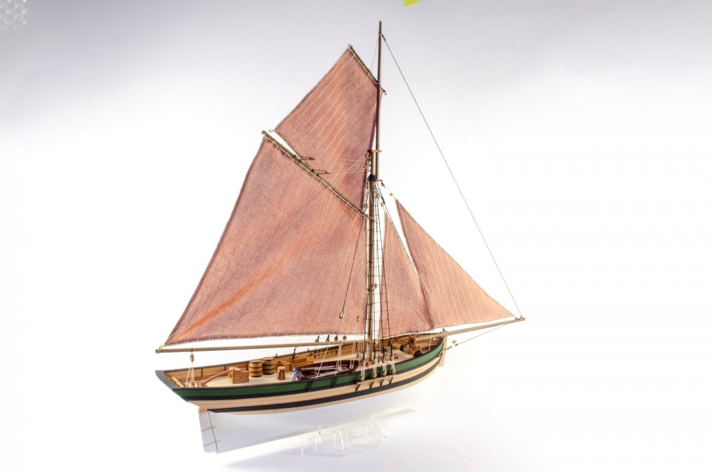
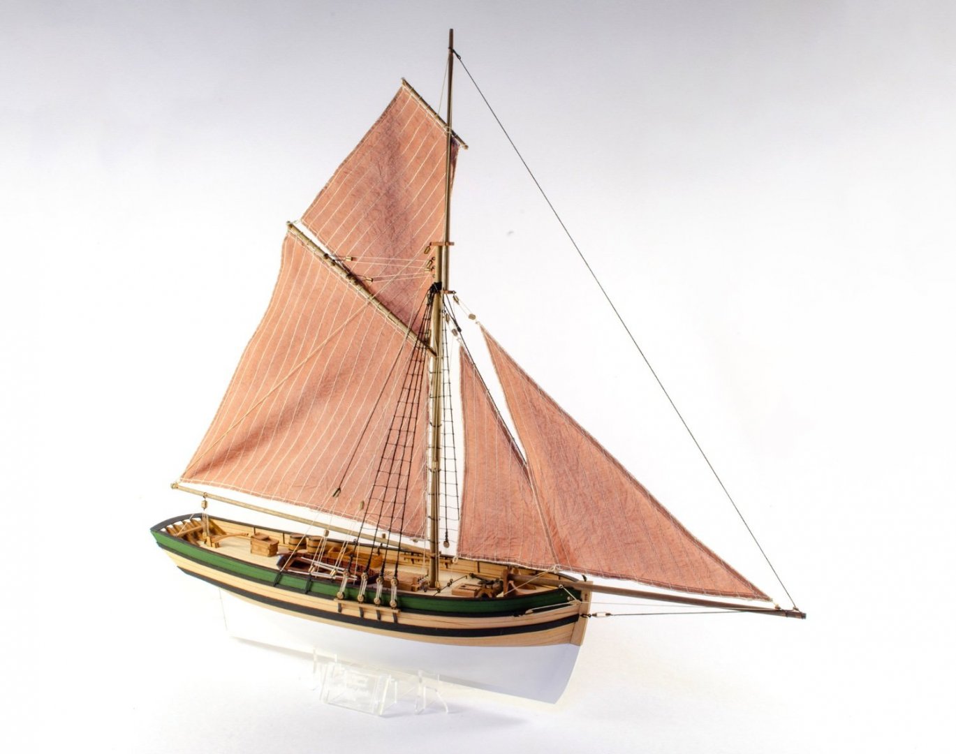
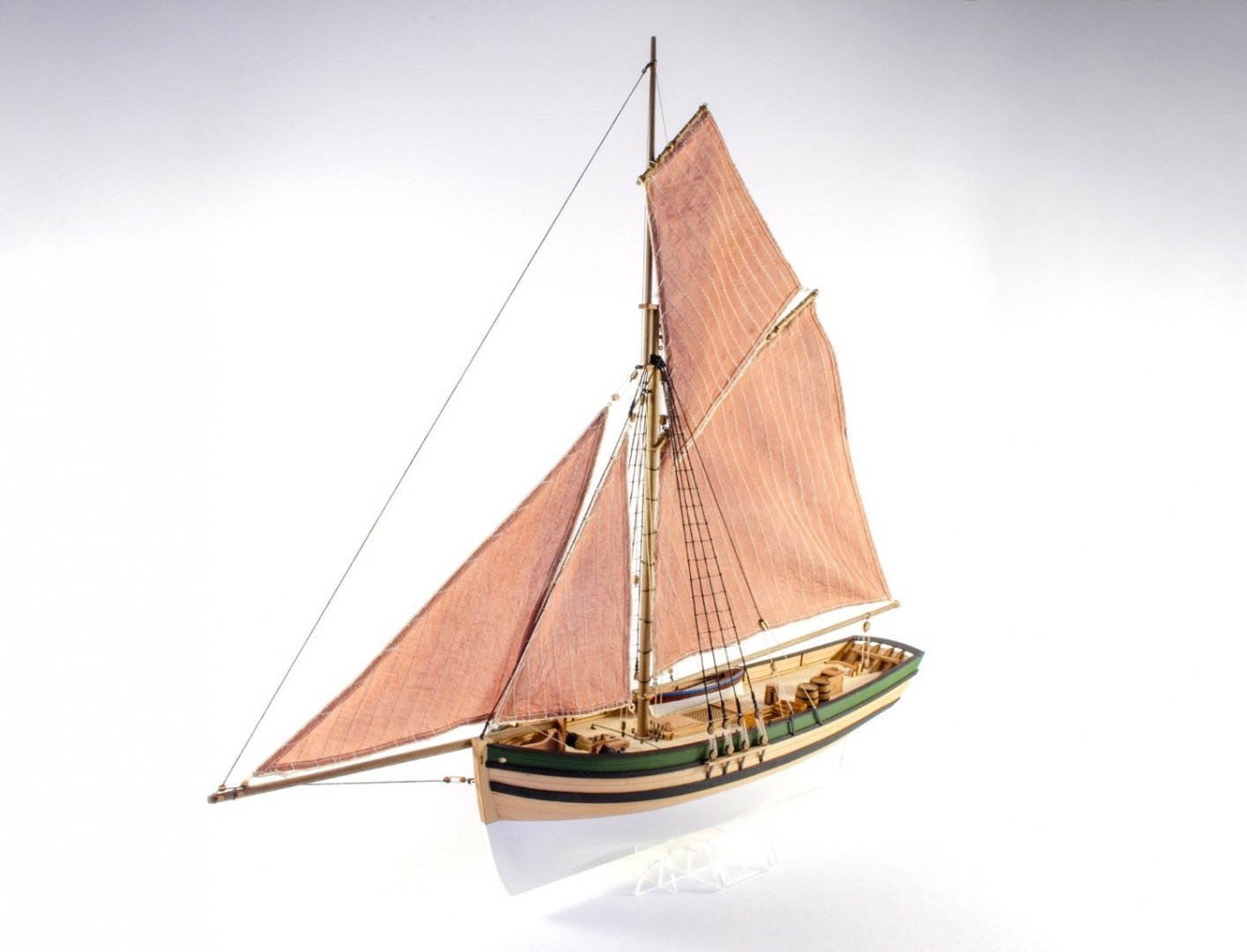
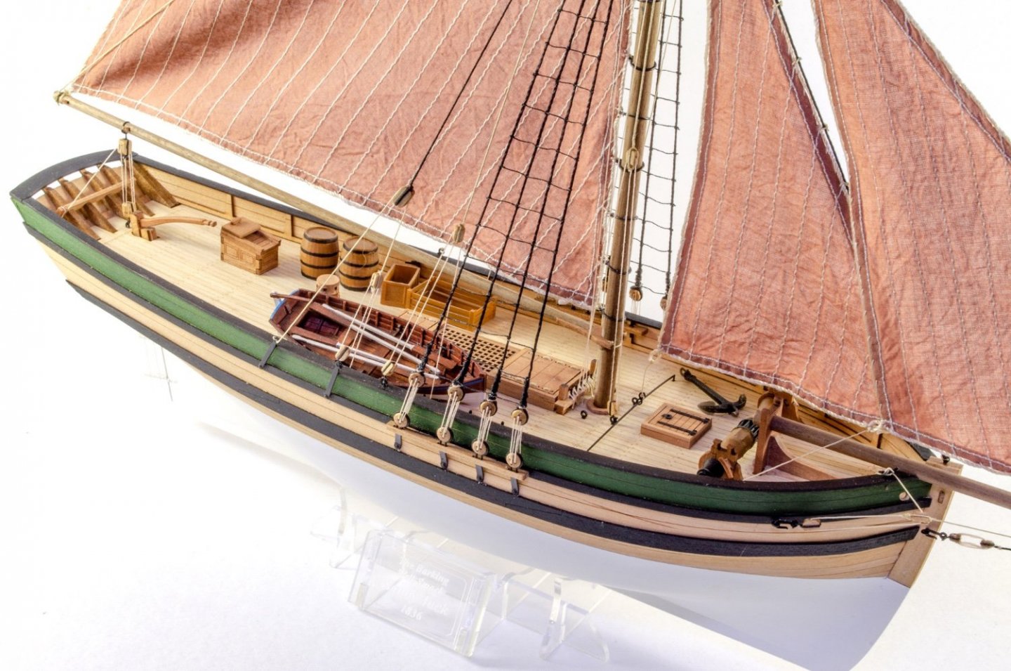
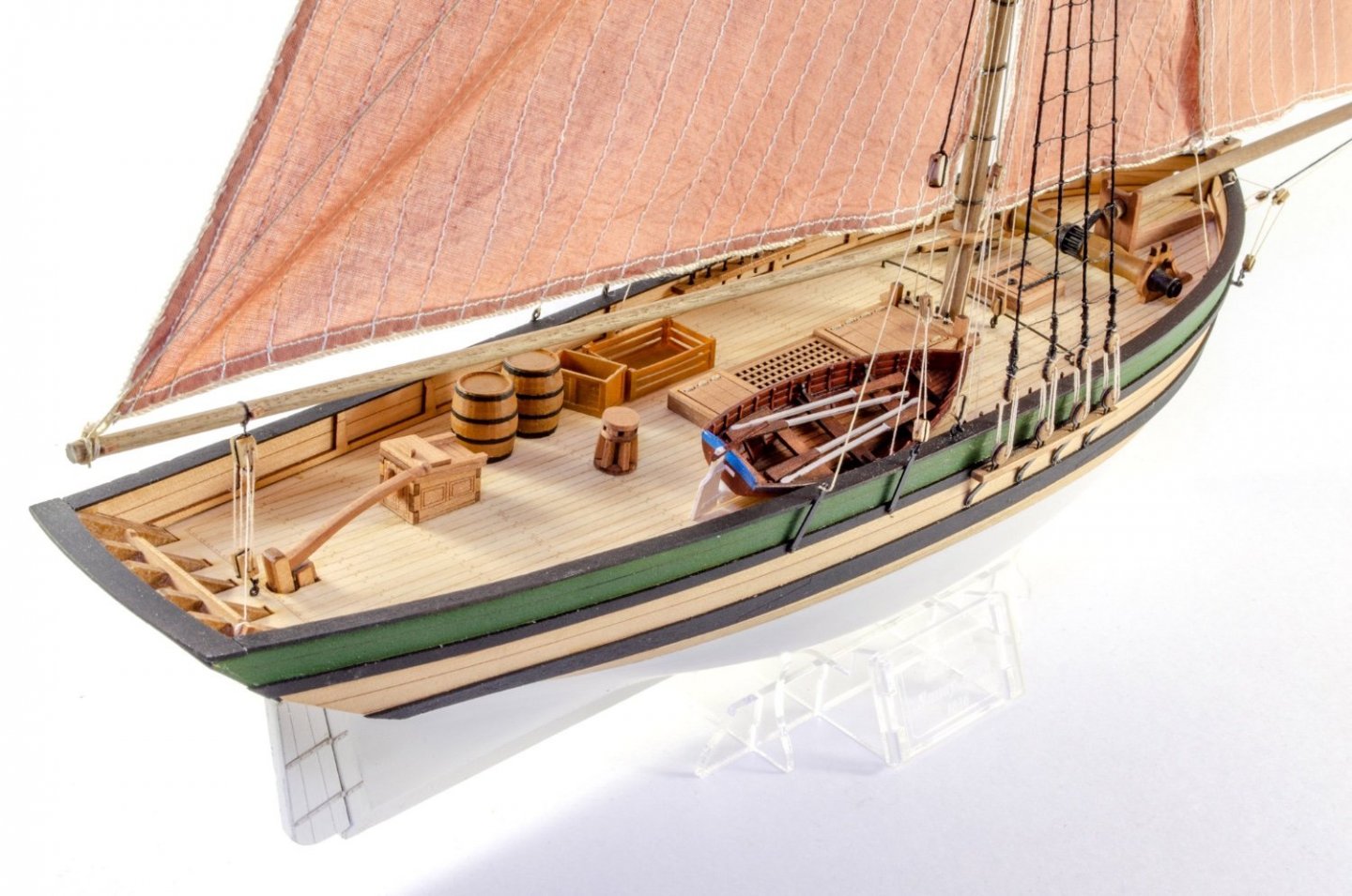
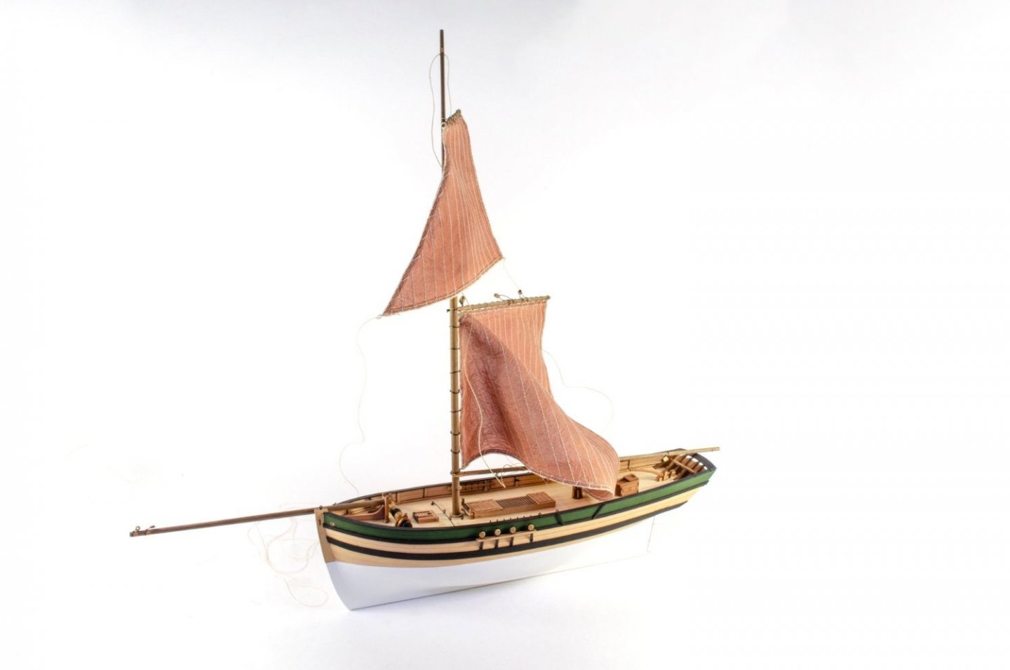
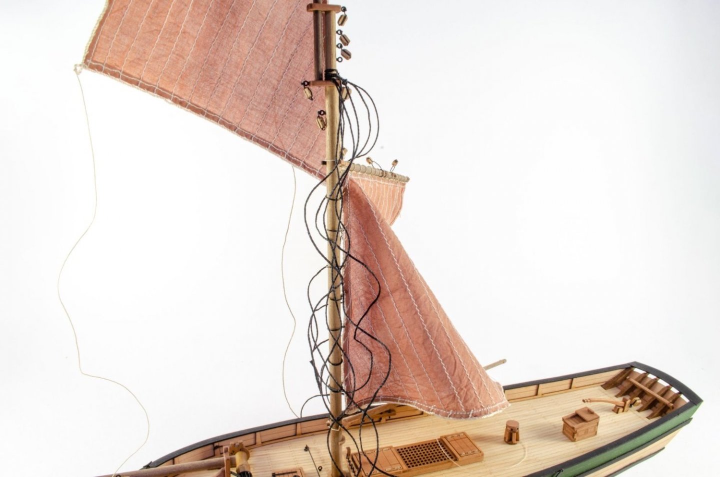
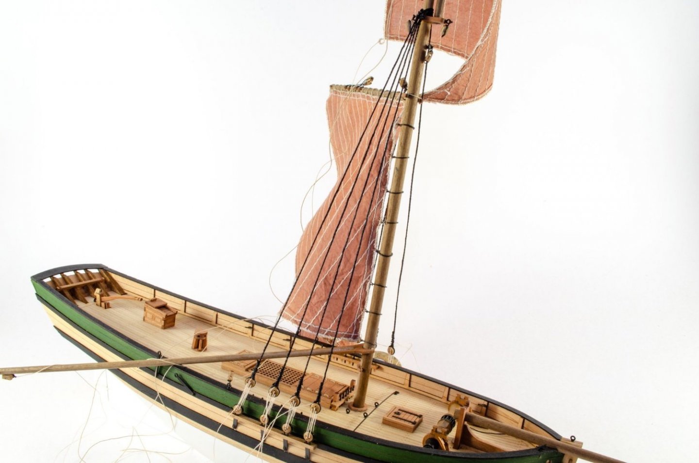
Saucy Jack is now complete, and it's a short break from the cave before I head back in to work on Ranger. Here are the finals. Hope you like them. Chris is now compiling the manual and box art, so it won't be too long now before this will be on sale.


- 29 replies
-
- 29
-
-
-
- well smack
- Vanguard Models
- (and 2 more)
-
kit review 1:65 Santa Maria – 1492 - Artesania Latina
James H replied to James H's topic in REVIEWS: Model kits
The Endeavour will be online within the next week too -
Wonderful stuff, and I like the breeze effect on those sails 👍
- 77 replies
-
- 3
-
-
- Erycina
- Vanguard Models
- (and 1 more)
-
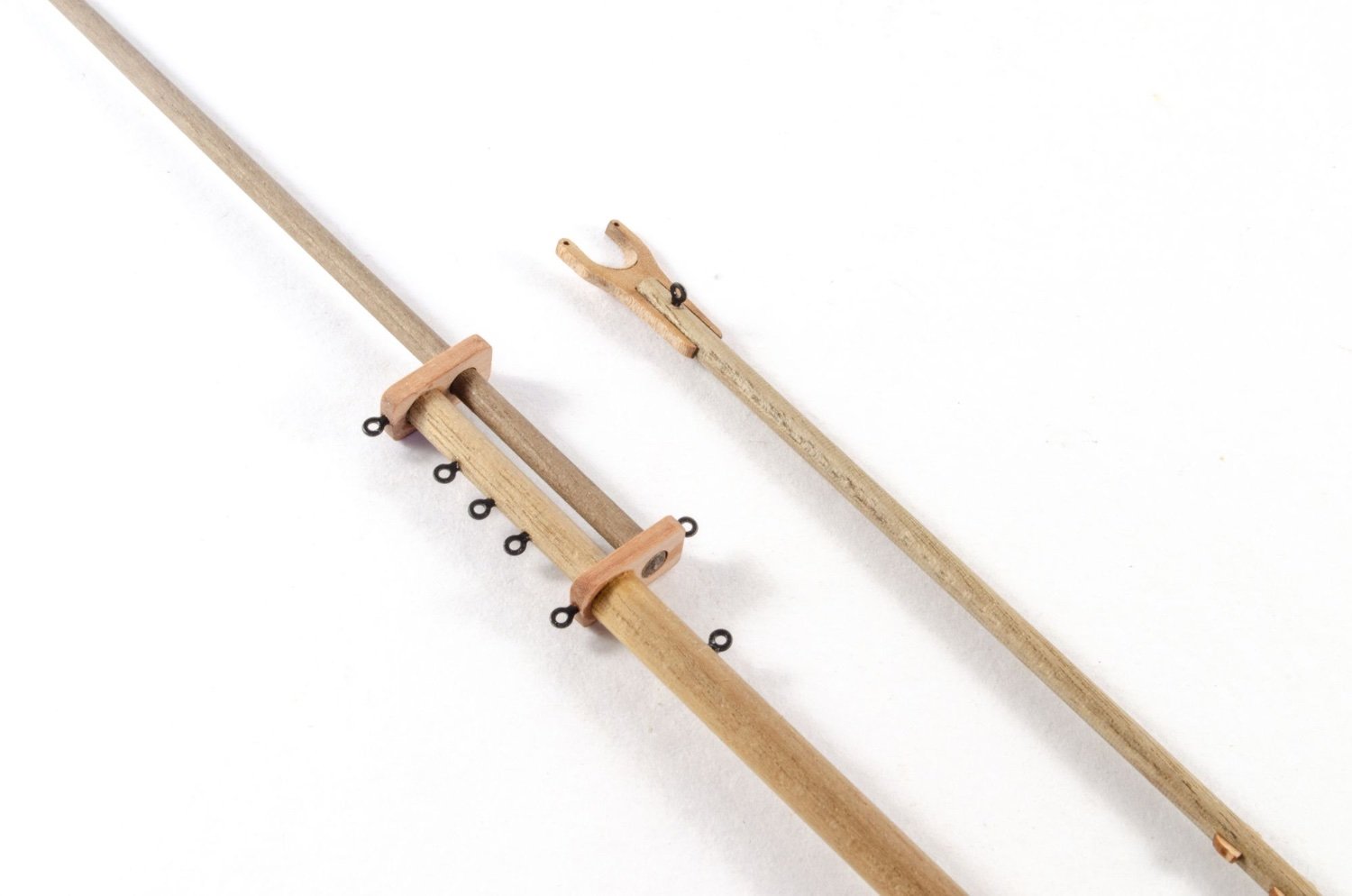
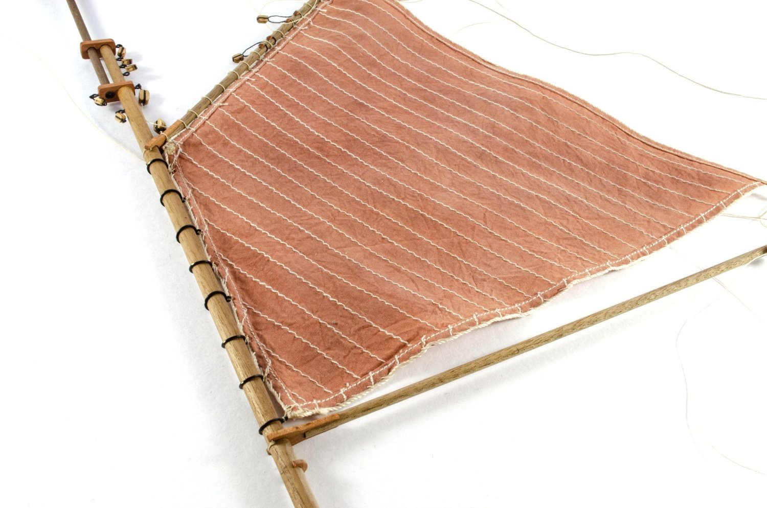
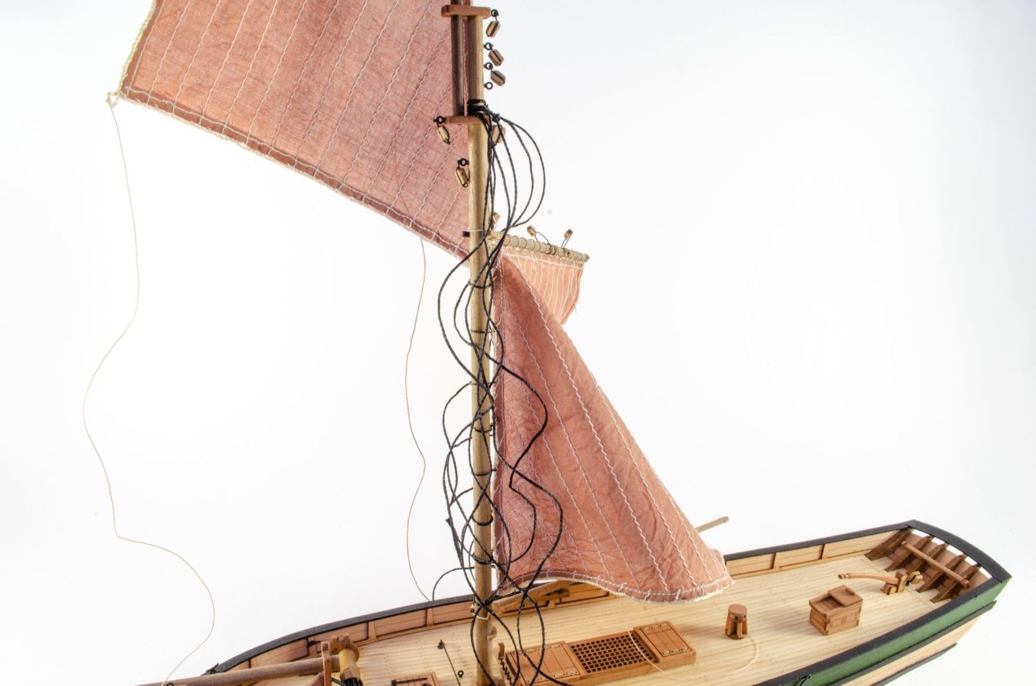
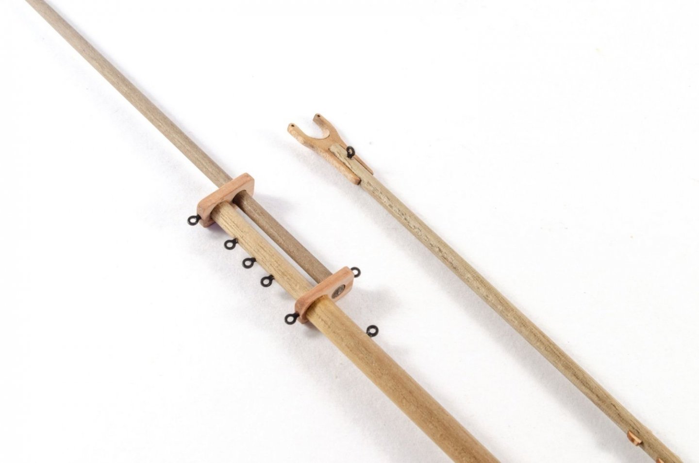
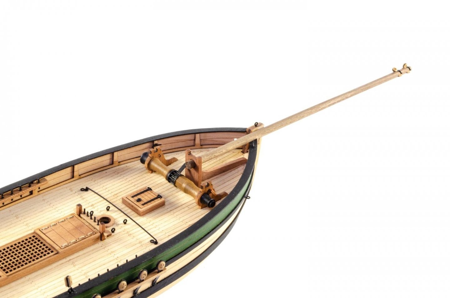
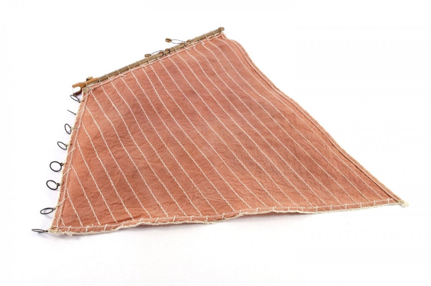
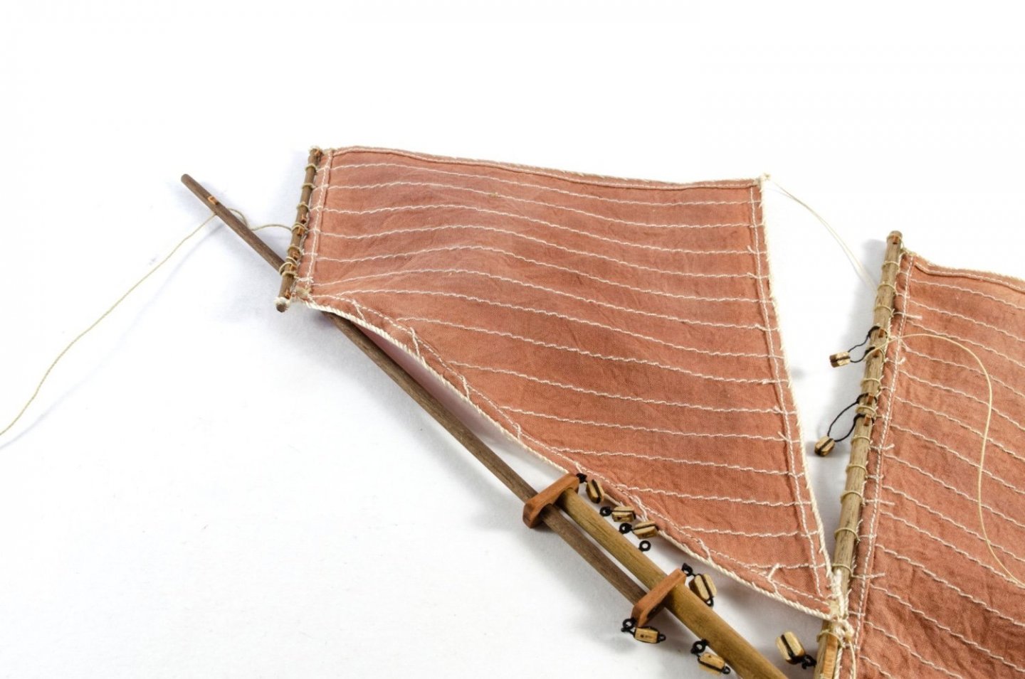
Just a quick, interim update before completion in the next days. Saucy Jack is probably one of the easiest boats to rig, even with the shrouds and rats. Very little timber work on mast/spars too. Here are a couple of the parts I made for this, ready for rigging blocks. The bowsprit is now added. The sails are first dyed in liquid RIT dye (Tan) and left in for a little longer than normal. I wanted these fairly light to suit the white hull underside and pear wood colours. Too much contrast would've hurt my eyes. Jack is finally masted and her full size is now clear. Yes, she's quite dinky! Proper rigging starts with the shroud lines wrapped around the masthead. And then tied off via 3mm deadeyes. I told you it was only a small update! More very soon when she's fully complete.

- 29 replies
-
- 12
-
-
- well smack
- Vanguard Models
- (and 2 more)
-
I've increased it to 200kb Some sites I'm a member of only allow 10k for a pic (!!!!) and max size of about 50px x 50px 🤪
-
Welcome to a fellow northerner. I love Manchester. Lower Turks at Shudehill is one of my favourites, and the Vine on Kennedy Street. 🍺
-
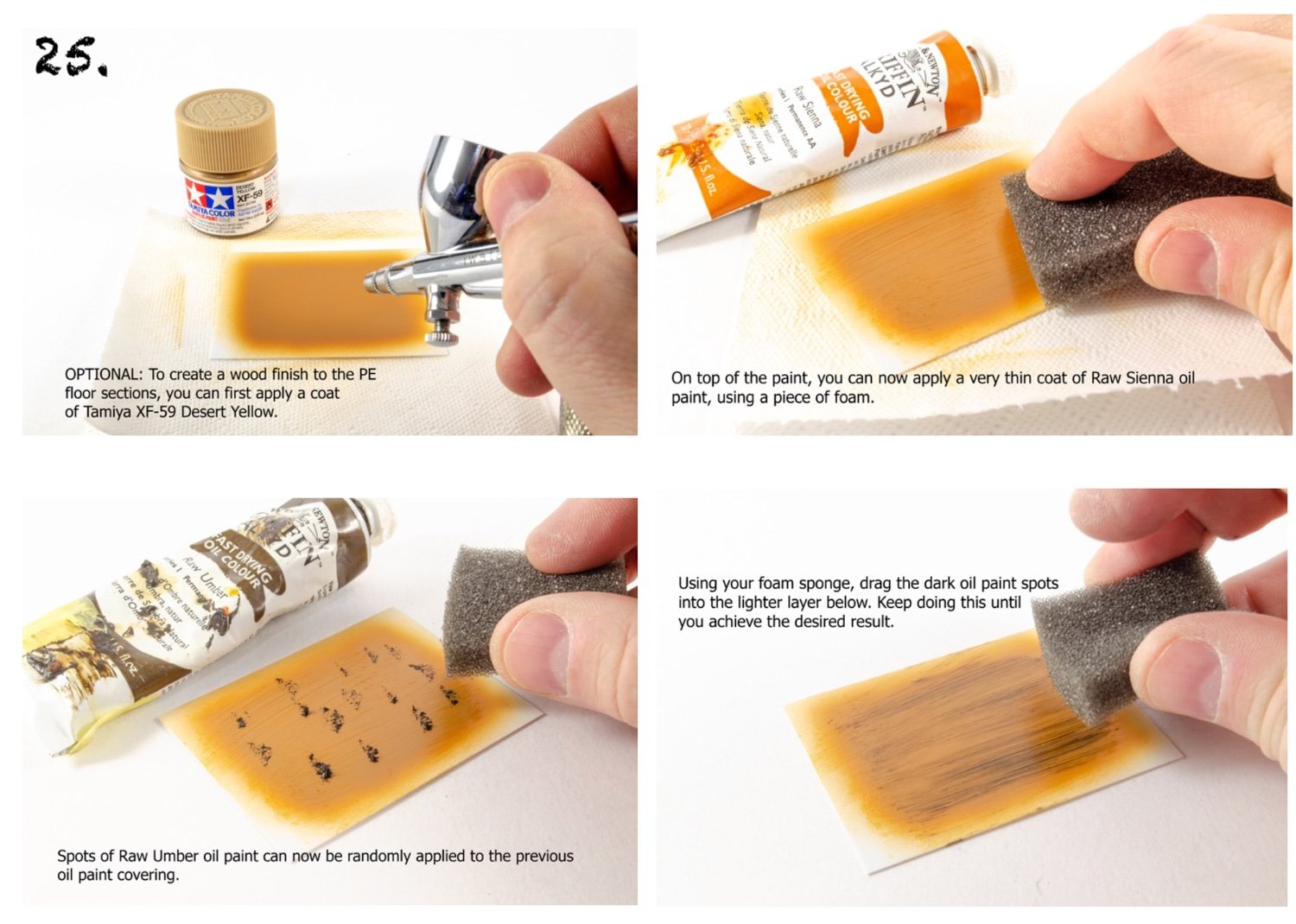
Cheers. It's been a lovely build too. I think I added another update just after that, while you were posting. Hull final pic shown. Here's the wood grain technique from the instructions I did for the VM ship's boats.

- 29 replies
-
- 11
-
-
- well smack
- Vanguard Models
- (and 2 more)
-
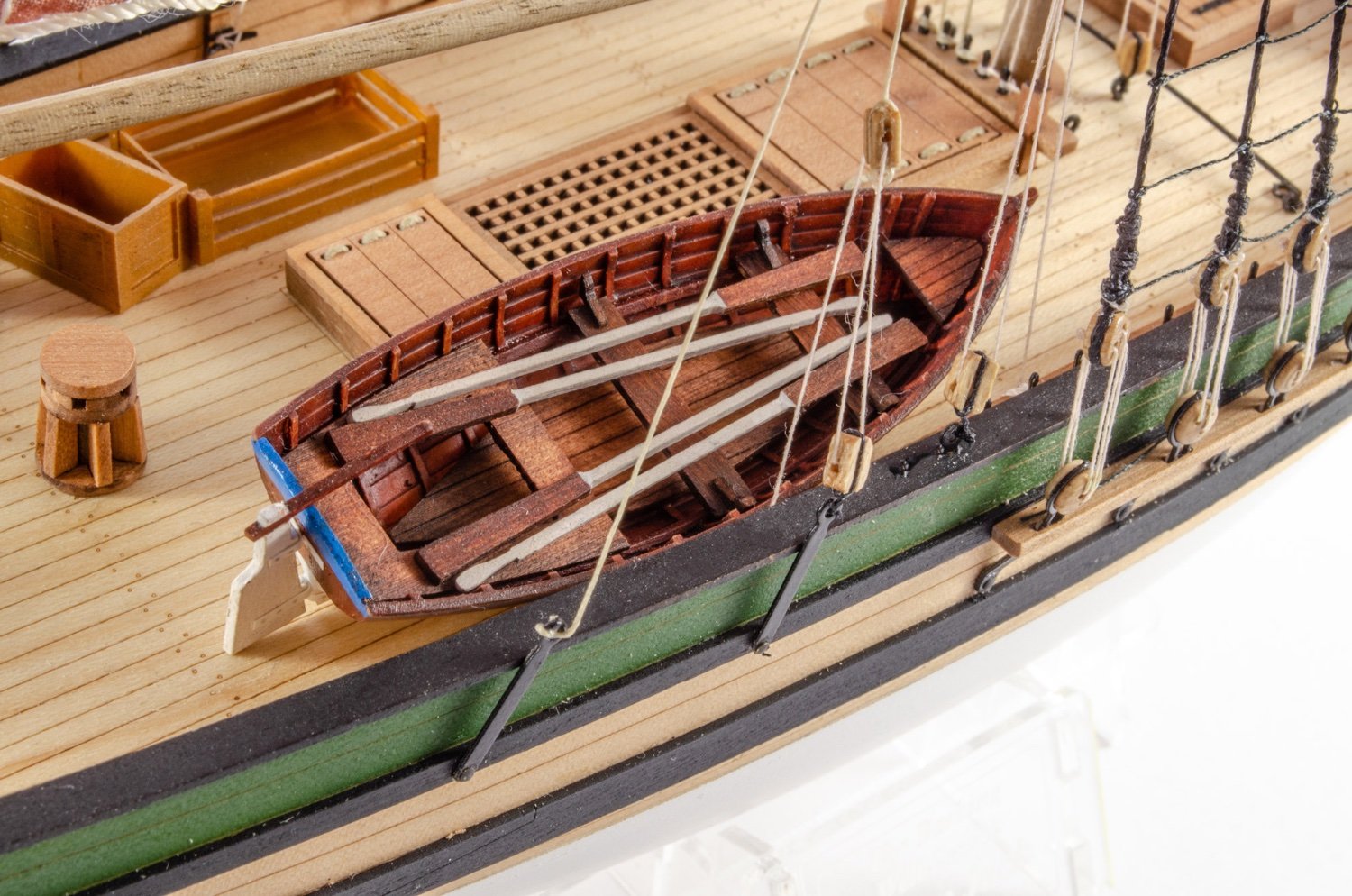
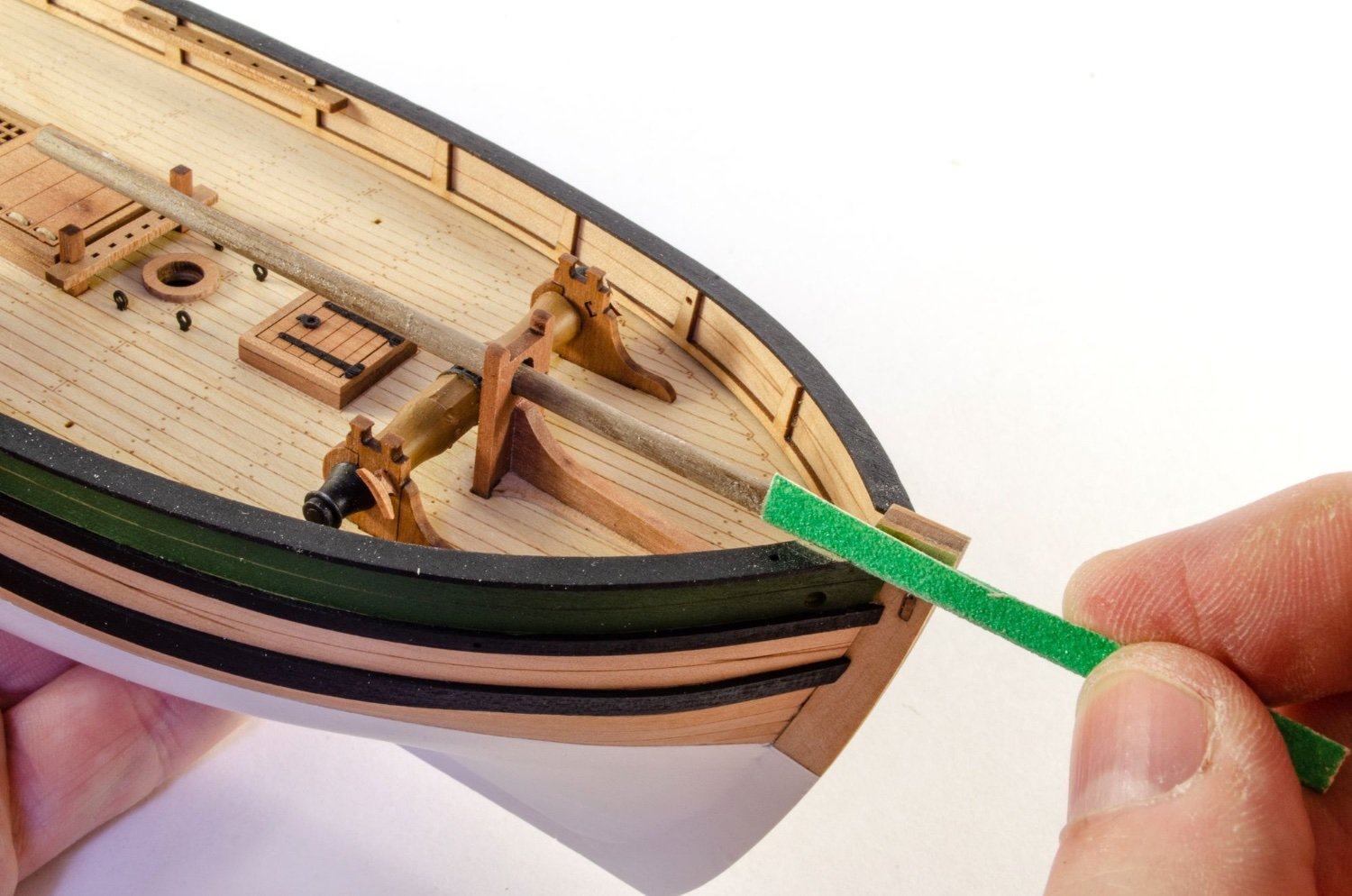
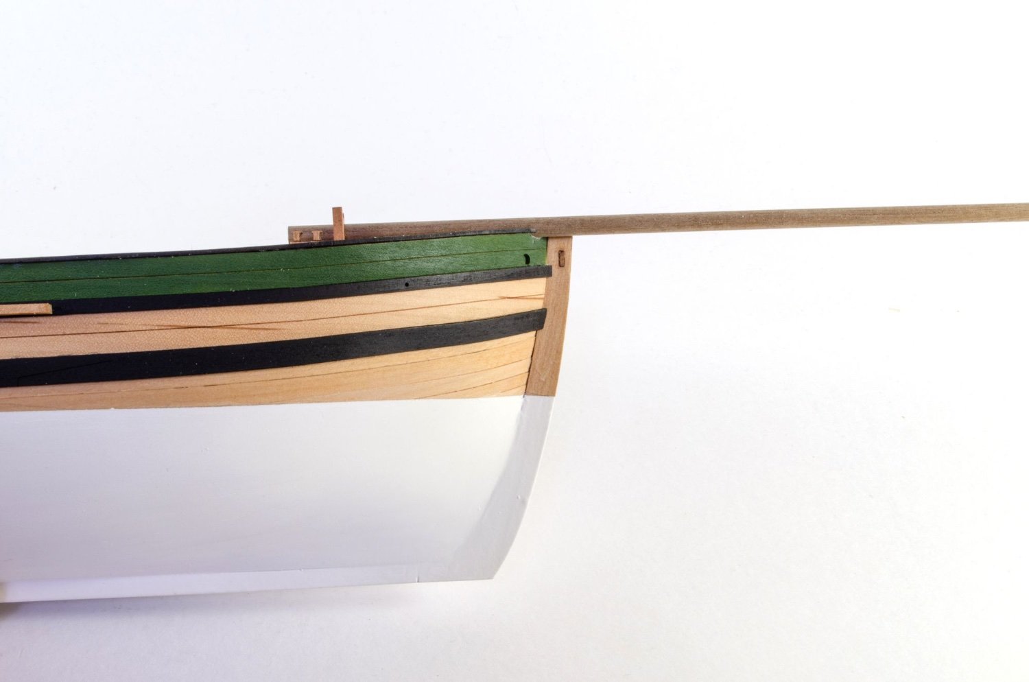
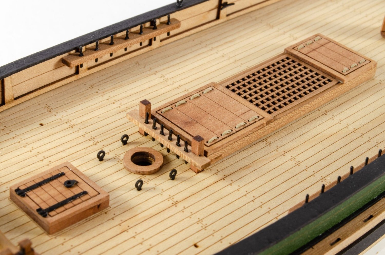
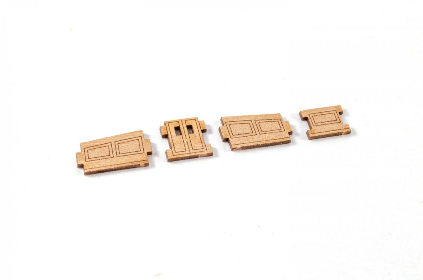
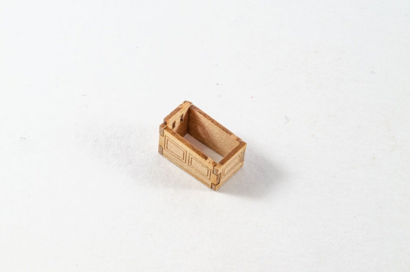
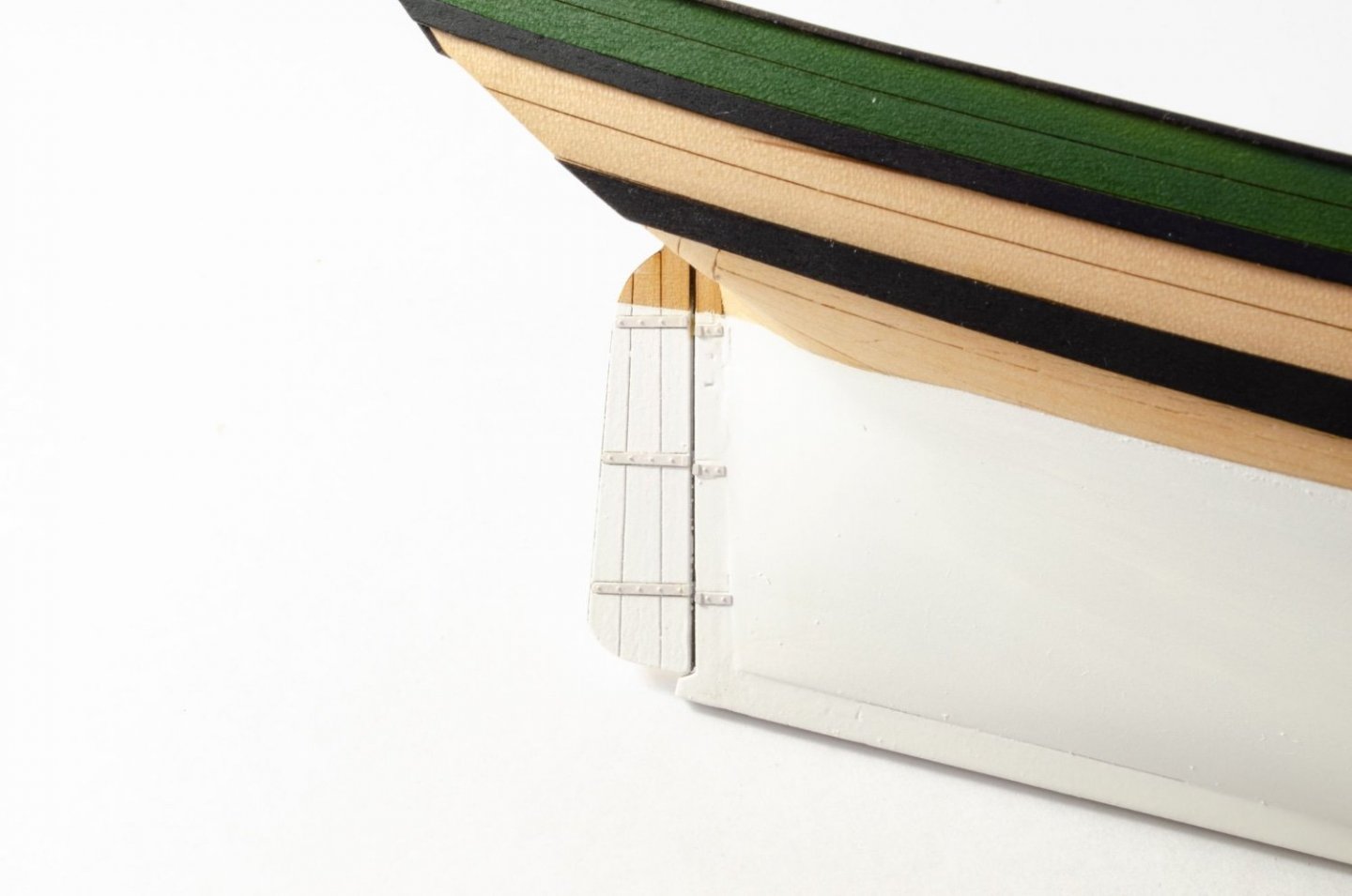
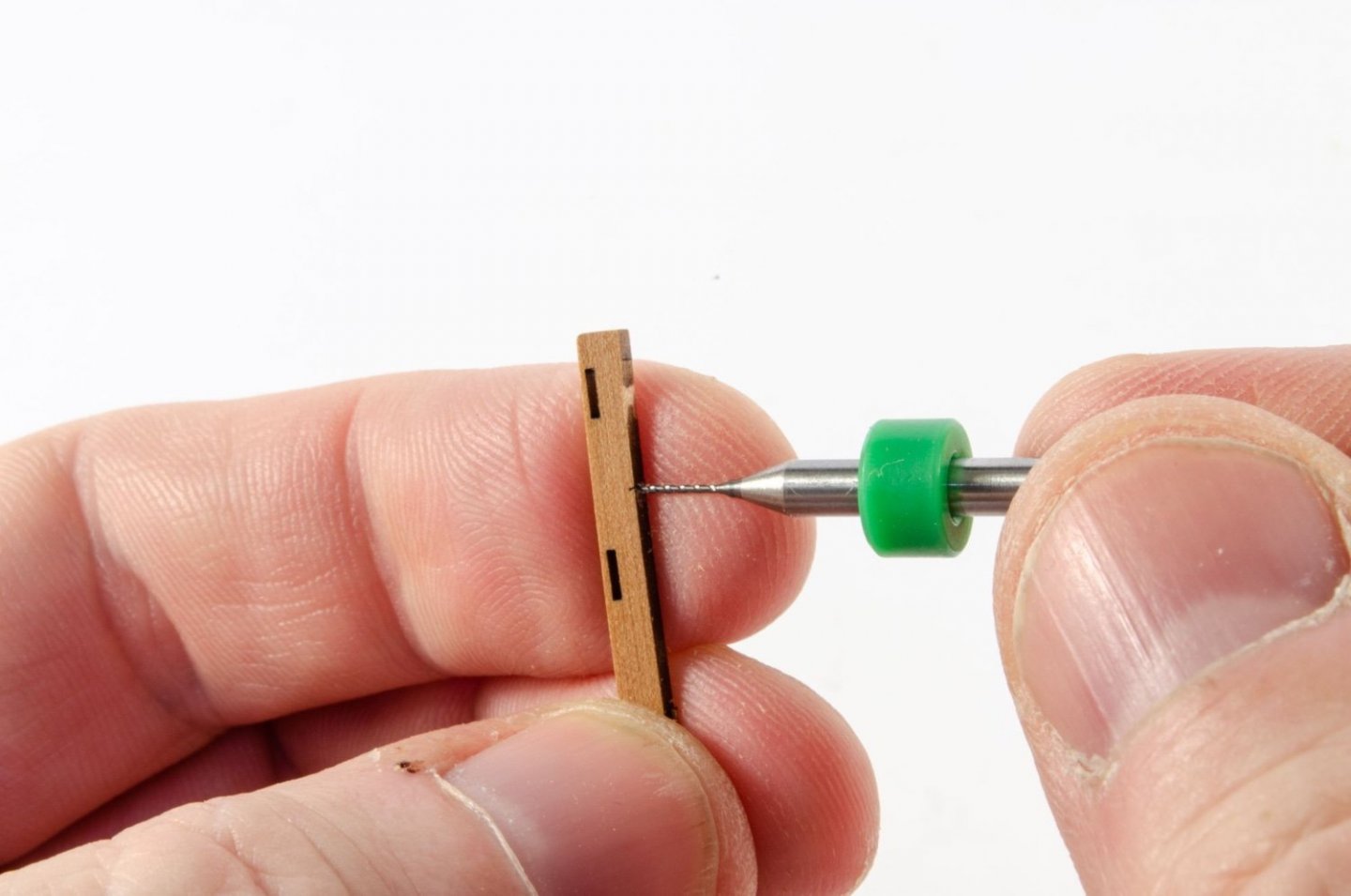
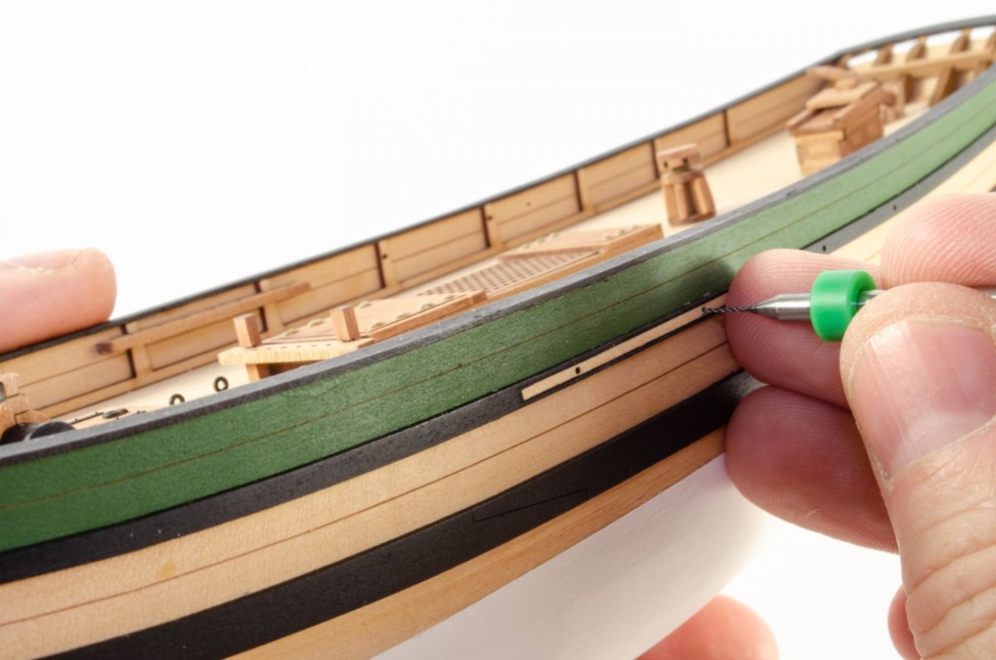
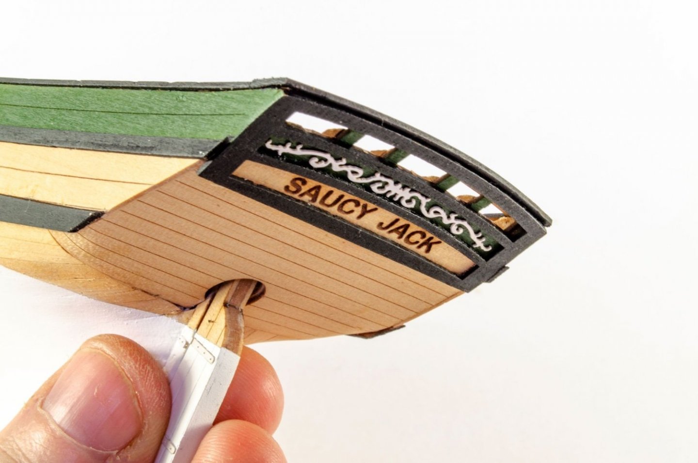
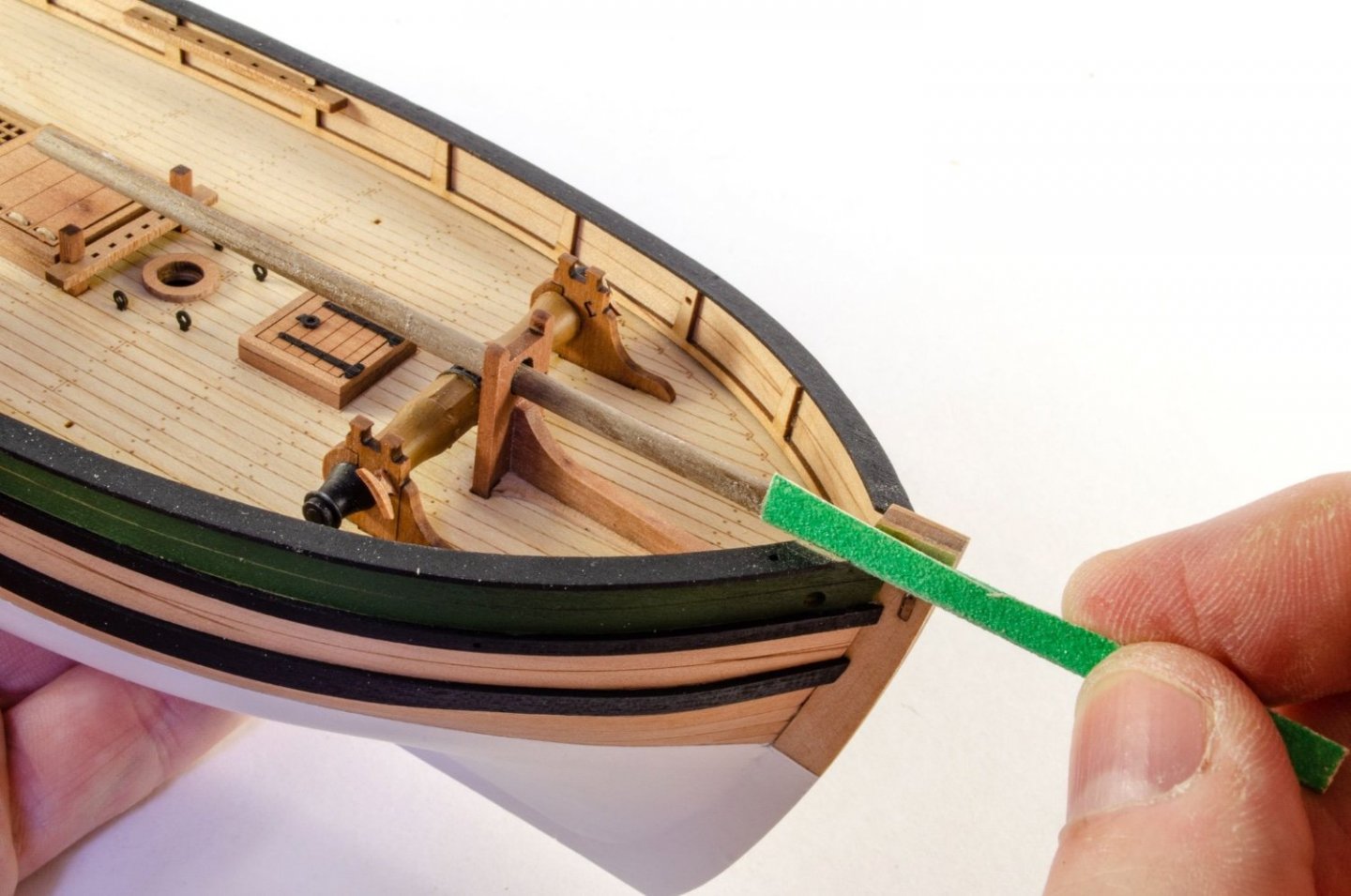
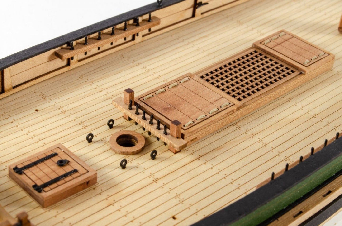
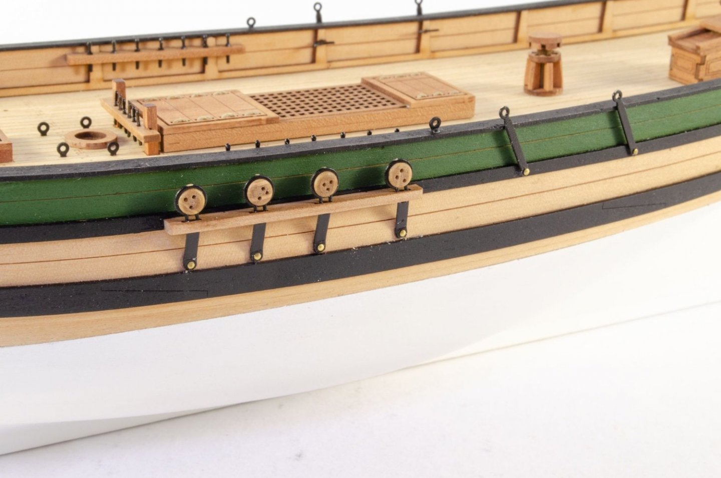
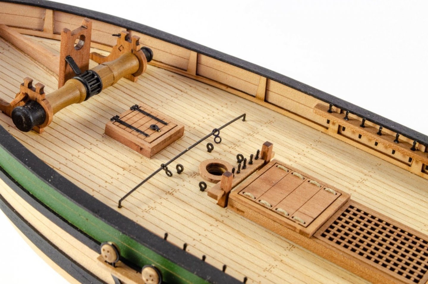
And onto today's second part of my update. I do it this way now so there aren't 30 - 40 pics in one post. The companionway is a nice, simple assembly. Nothing difficult to fathom here. The rudder can now be permanently fitted, and the tiller shaped and glued into place. PE rudder hinge straps are now painted and glued into place with CA gel. The channels on Jack are very narrow, and engraved lines on them indicate where you need to drill through and insert shortened brass pins for some extra strength. I also deepen the engraved holes on the upper rails, going into the bulwarks about a millimetre or so. The channels are then glued into place. Notice the area on rail left unpainted, where the engraved position was given. That was masked while painting the rails, so there's a good, clean gluing connection. Jack's stern frieze is now painted white and glued into the green panel. Jack's bowsprit is roughly parallel to the bottom of the keel/waterline. As the bowsprit is from 4mm dowel, I used a 3mm piece, wrapped in some sandpaper, and used the bowsprit post as a guide for sanding down the gunwale and bulwark to accommodate it. A simple task that took no more than a couple of minutes. Other ironwork is now fitted, such as the bulwark cleats, eyelets and belaying pins. 3mm deadeyes are now fitted to the chainplates and secured to hull. The brass pins will then be painted over (not shown on these pics). Saucy Jack's completed hull! Next up will be masting and rigging.


- 29 replies
-
- 14
-
-
- well smack
- Vanguard Models
- (and 2 more)


_bomb_vessel_RMG_J0387.jpg.af53eba1036bbbad25ca652bf3dfc731.jpg)