HOLIDAY DONATION DRIVE - SUPPORT MSW - DO YOUR PART TO KEEP THIS GREAT FORUM GOING! (Only 75 donations so far out of 49,000 members - C'mon guys!)
×


James H
-
Posts
6,100 -
Joined
-
Last visited
Content Type
Profiles
Forums
Gallery
Events
Everything posted by James H
-
 Not long to go then I'm about to start a couple of little boats and the next fisher in the series.
- 28 replies
-
- 1
-

-
- vanguard models
- Brixham trawler
- (and 2 more)
-
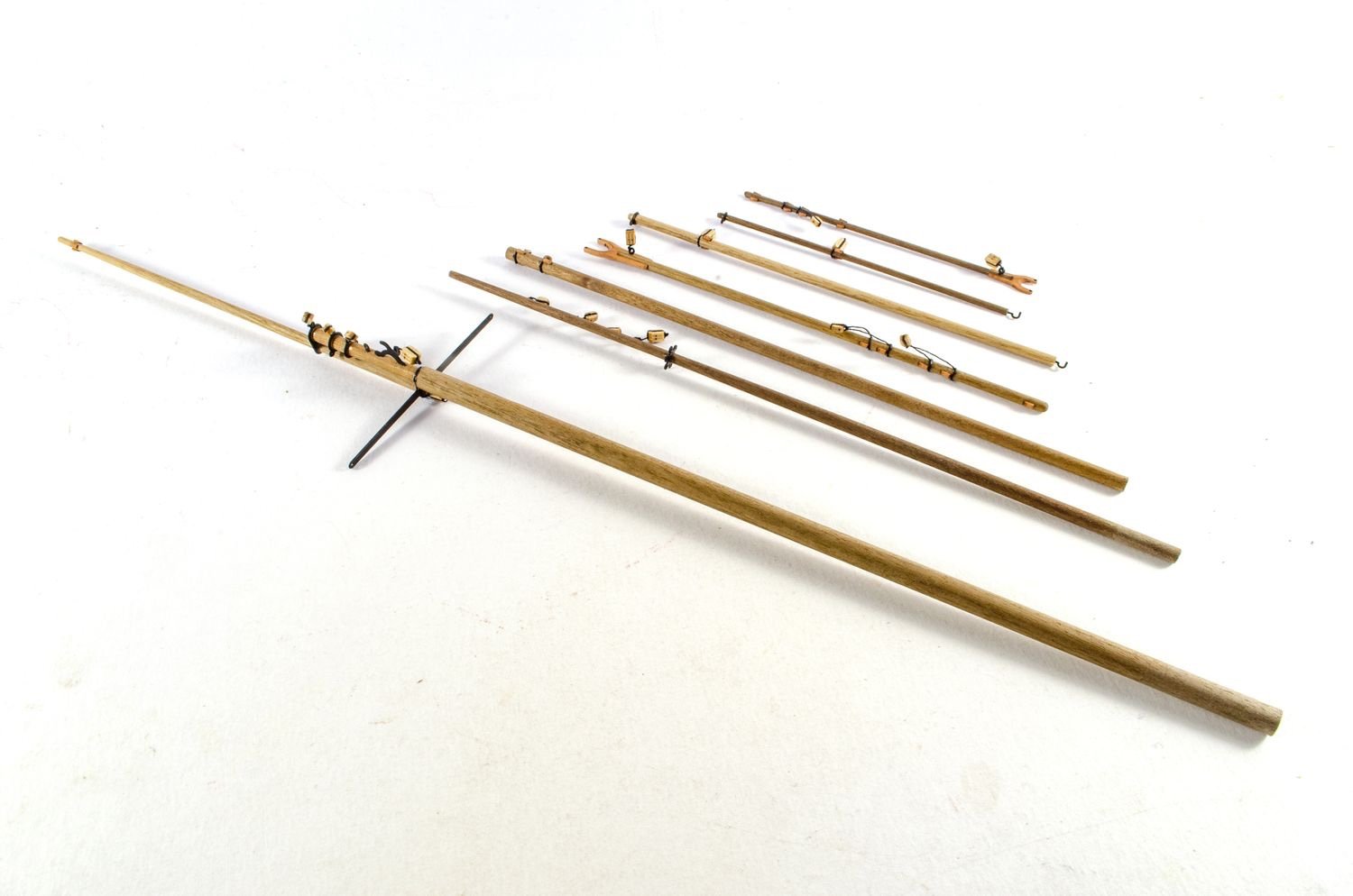
There's hardly any taper on these. I just spun it in my fingers and sanded with a block 😁
- 28 replies
-
- 2
-
-
- vanguard models
- Brixham trawler
- (and 2 more)
-
Error code 200
James H replied to Blue Ensign's topic in Using the MSW forum - **NO MODELING CONTENT IN THIS SUB-FORUM**
It is still there. I'm still currently trying to fathom it out. Whatever the problem is, it's likely a host issue setting that needs to be fathomed, or it could be caused by our Sucuri proxy. This will take some time, especially as it's now Christmas and I have numerous other family commitments that will take priority. For the time, just keep re-uploading any failed images.- 27 replies
-
- 13
-
-

-
Error code 200
James H replied to Blue Ensign's topic in Using the MSW forum - **NO MODELING CONTENT IN THIS SUB-FORUM**
Ok, I'll look more closely at this tonight. -
That's looking real nice without a doubt. One way of stopping bleed around masking like that is to first apply a little thinned varnish to the paint area after masking, so the varnish creates a seal the paint can't bleed through.
- 857 replies
-
- 9
-
-
-
- Sphinx
- Vanguard Models
- (and 1 more)
-
Error code 200
James H replied to Blue Ensign's topic in Using the MSW forum - **NO MODELING CONTENT IN THIS SUB-FORUM**
Try uploading your photos in smaller batches and let us know how it goes. -
I'm sorry Chuck, I no longer have the completed model.
- 355 replies
-
- 1
-
-
- vanguard models
- Sphinx
- (and 1 more)
-
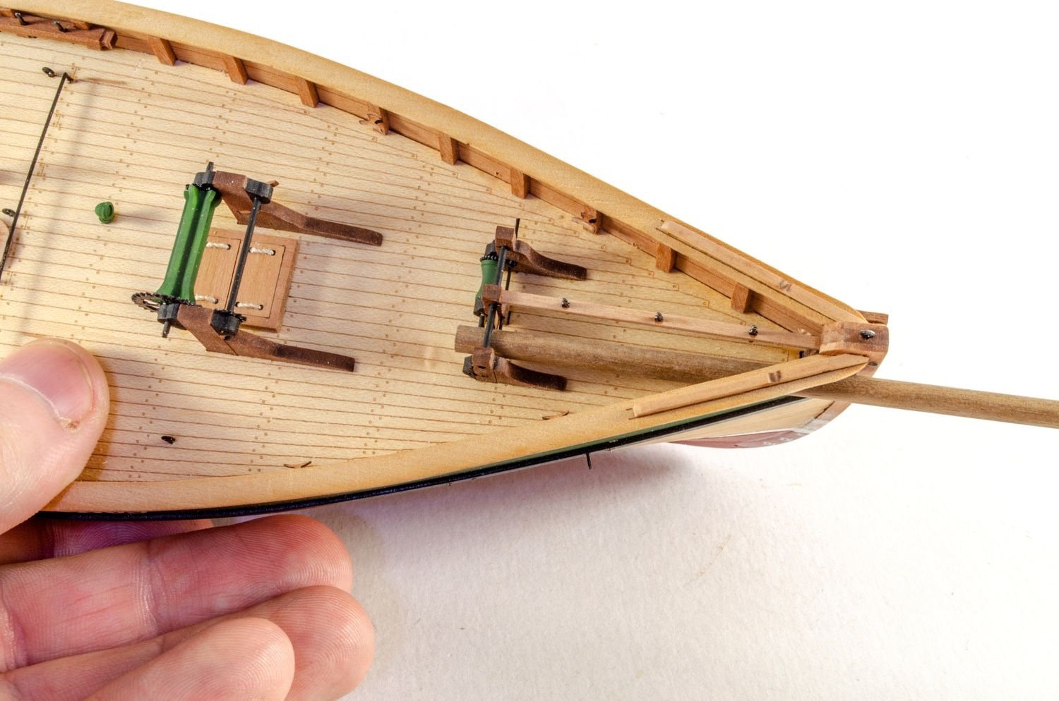
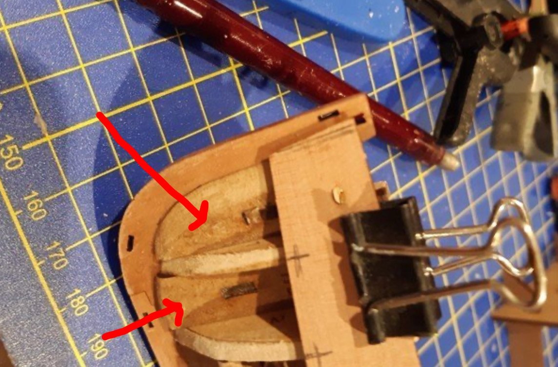
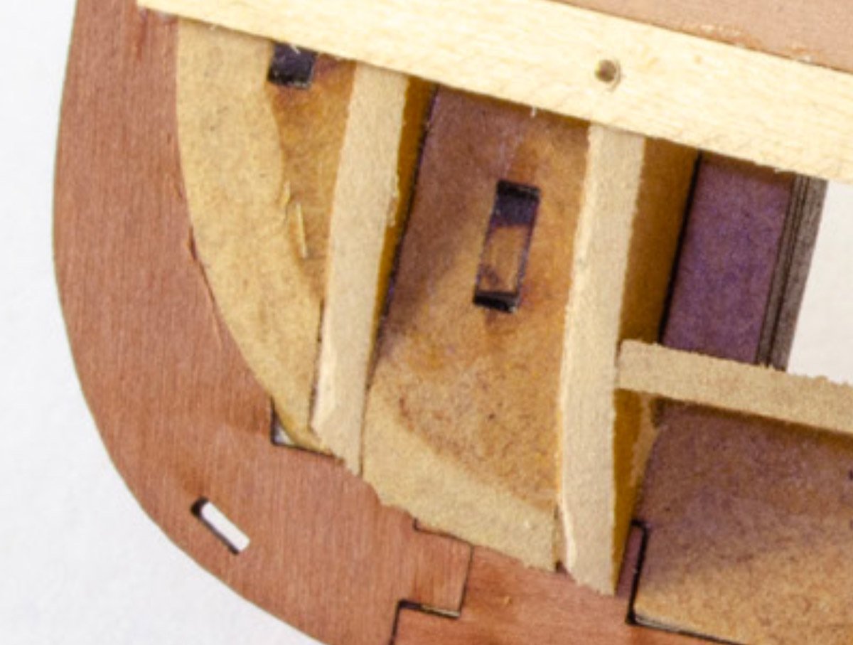
Great to see this lovely little boat getting some attention. Just a quick observation, those MDF blocks that fill between bulkheads 1 & 2, and those that sit in front of bulkhead 1, then do need to be shaped/bevelled more than in this picture. Those should be sanded down more in profile with the adjoining bulkhead bevels: If that fore block isn't tapered more, the planks would need to be bent around a curve to reach the stem, or they would sit over it and terminate too far forward. This is the pic I did for the manual:
- 206 replies
-
- 7
-
-
-
- Vanguard Models
- Brixham trawler
- (and 2 more)
-
HMS Granado 1742 Kit - CAF Model - 1:48 Scale
James H replied to cafmodel's topic in Wood ship model kits
That looks gorgeous, Tom. The MSW review will be online in the next week or so, as I finally settle down for Christmas. -
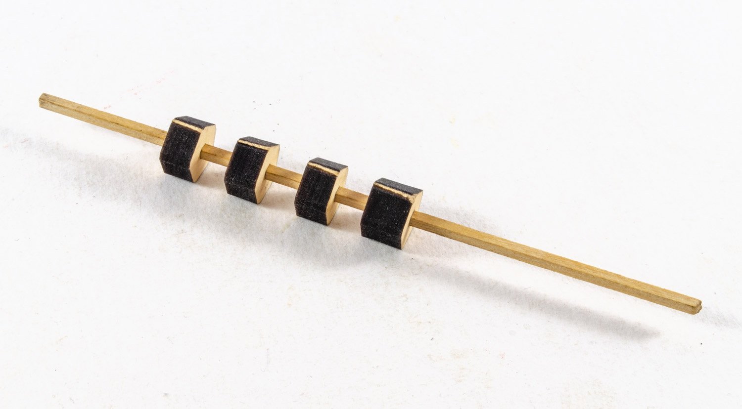
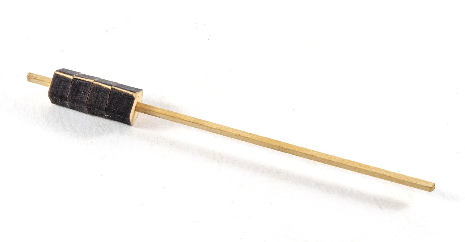
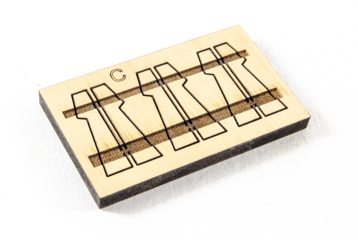
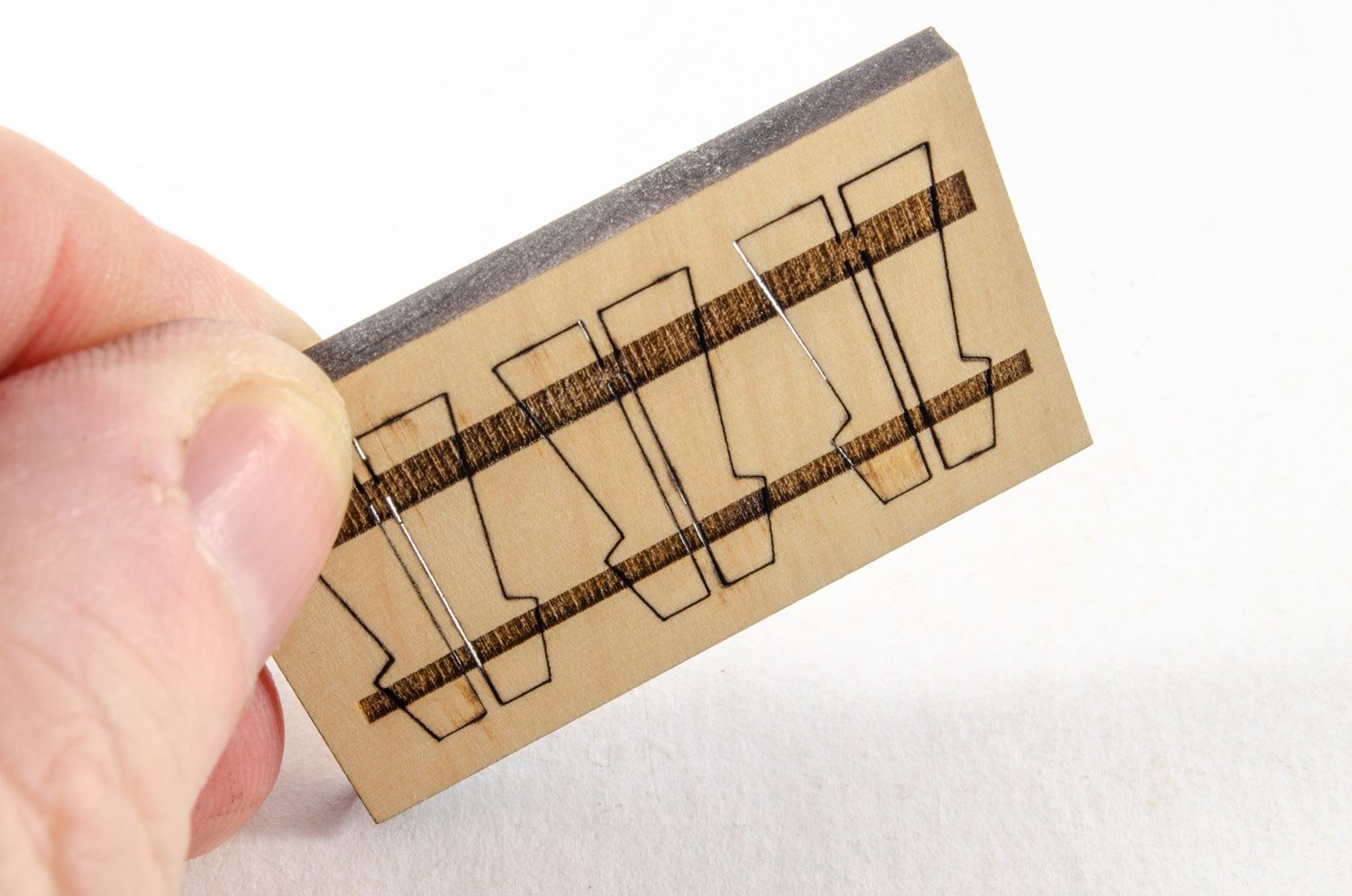
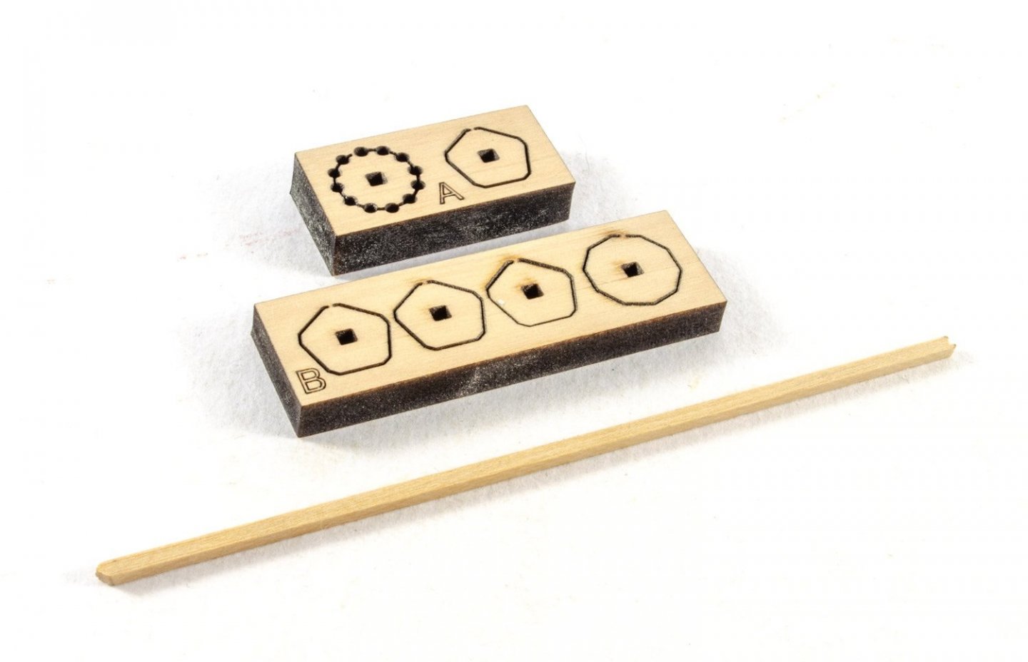
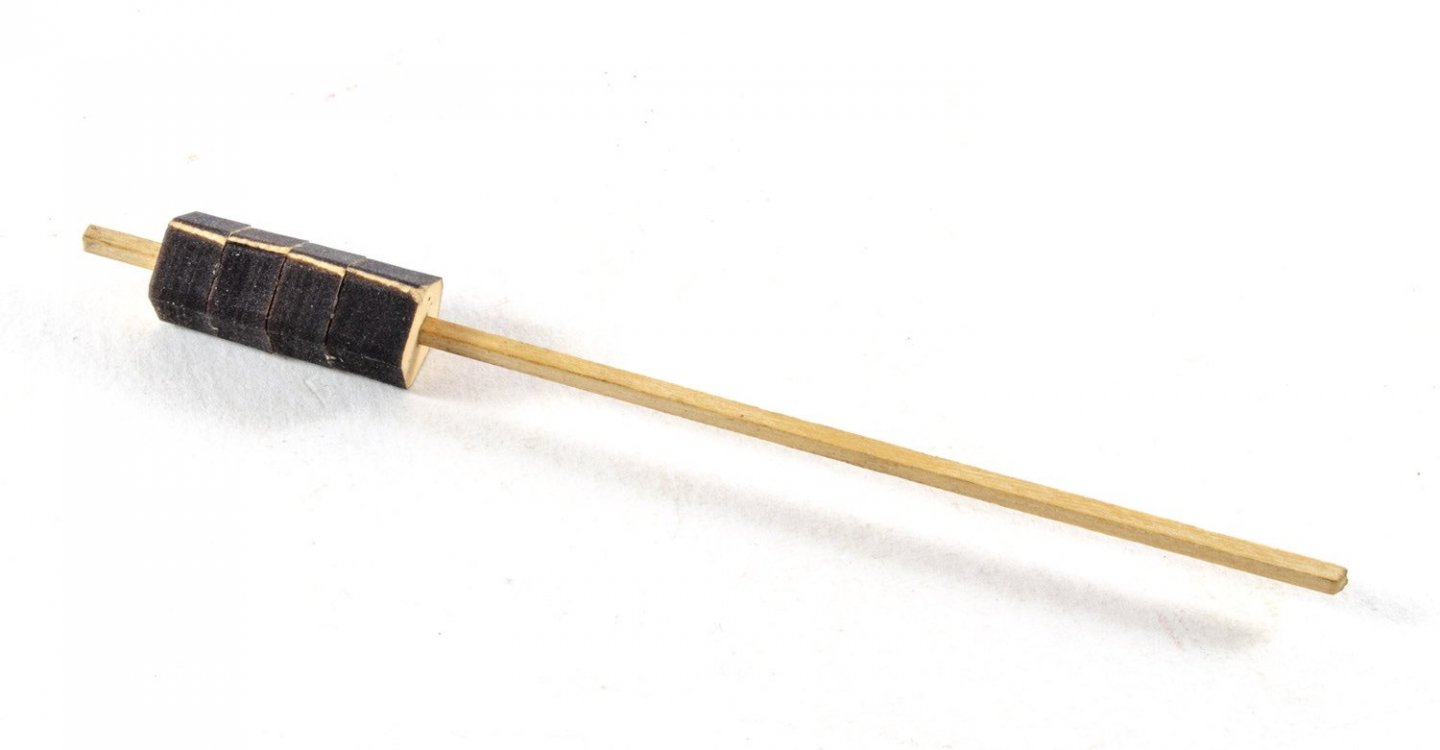
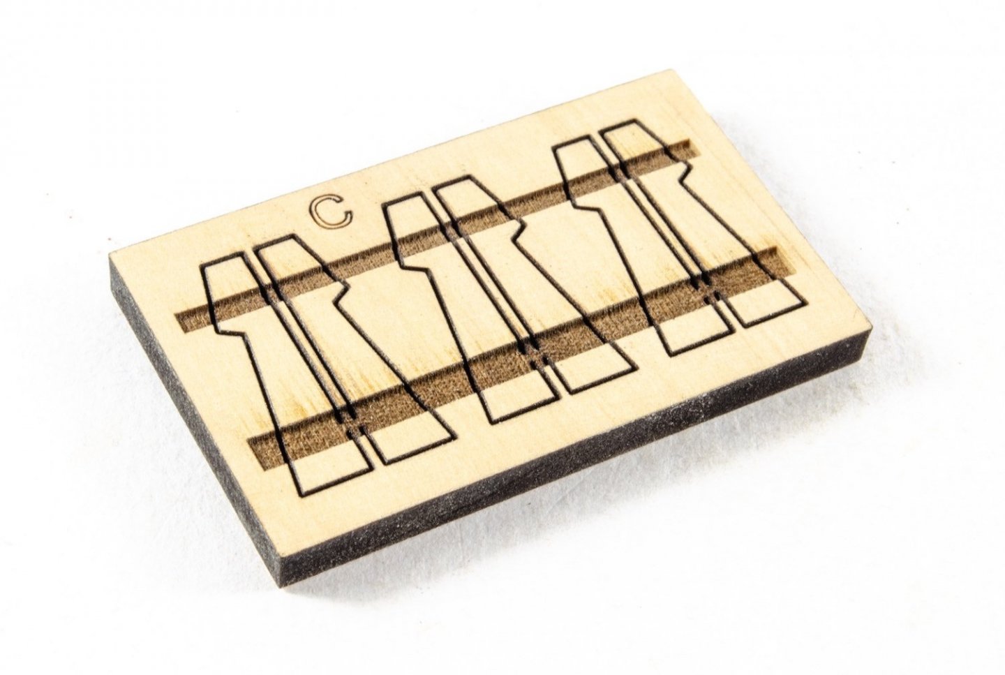
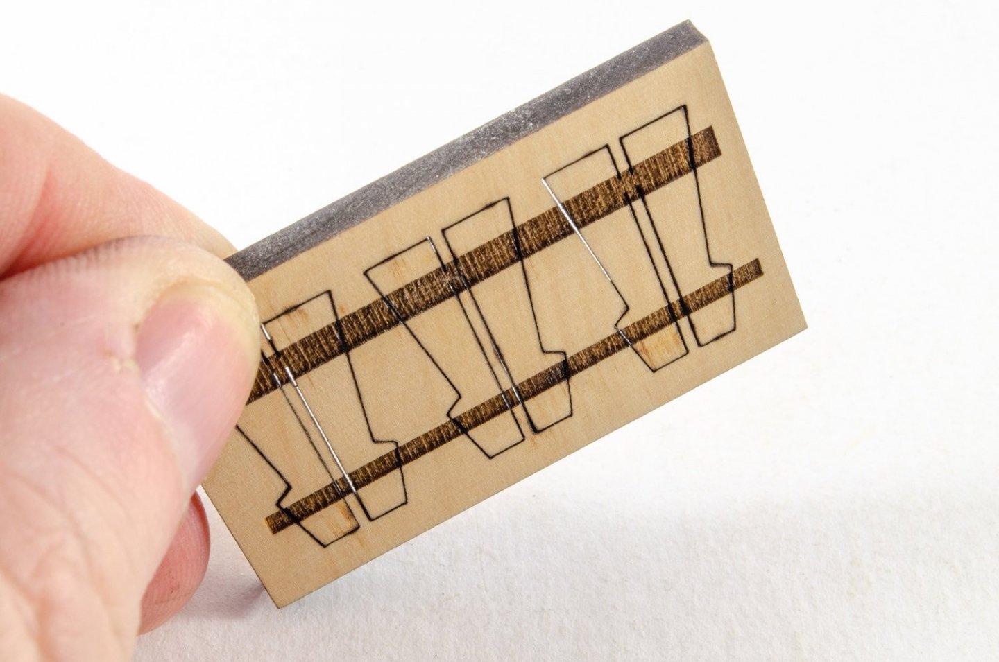
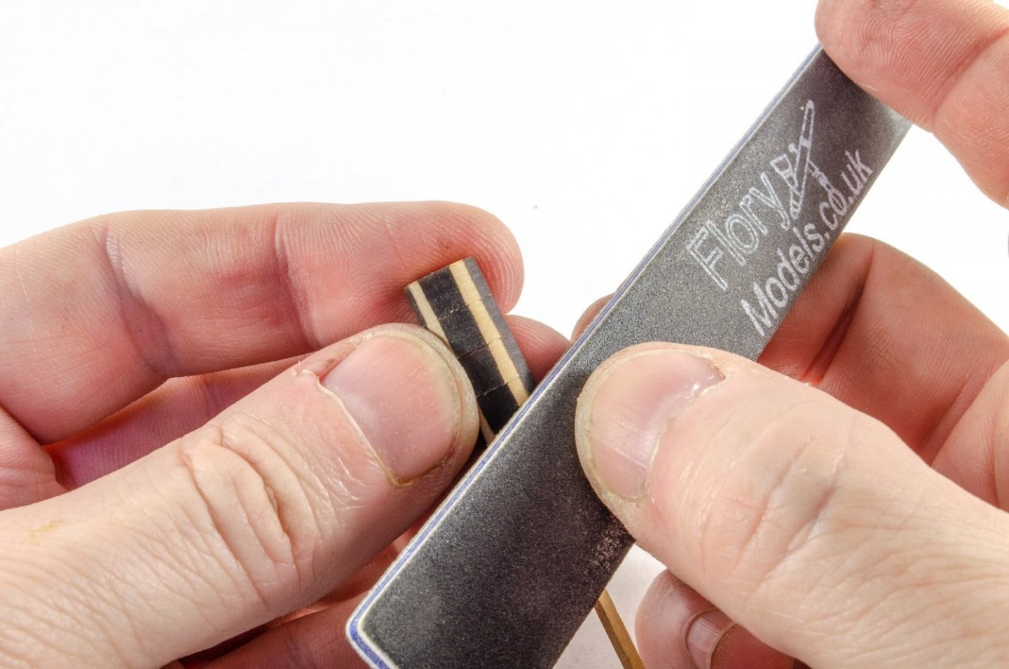
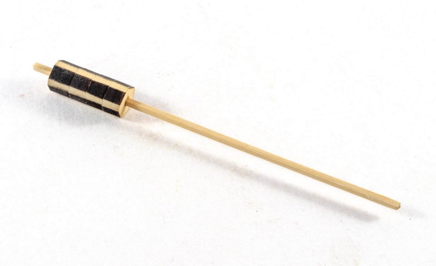
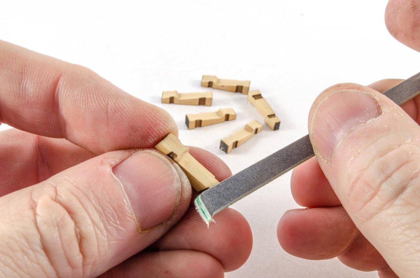
Only a little update as my workshop is a little indisposed at the moment, plus I'm heavily into a PlayStation game too. 😆 I really do like the colour of the timber in this little kit. The fest parts to use are for making the lower capstan. The column sections are first slid onto the 1/16 square strip. Note the thicker one sits at the end. These are then glued to each other, but NOT the strip! Aligning these is easy as you simply align the edges which have the connection tabs present. When dry, the narrow edges are cleaned up and evened out. These will be visible between the chocks. Now onto the whelps. This sheet is engraved on both sides to accommodate the chocks. As we all know, removing char is important 😉 The char on the outside edges of these is now carefully removed. More as soon as I can get back into my workshop!

-
Looking forward to seeing you work on this lovely little boat 😃
- 206 replies
-
- 2
-
-
-
- Vanguard Models
- Brixham trawler
- (and 2 more)
-
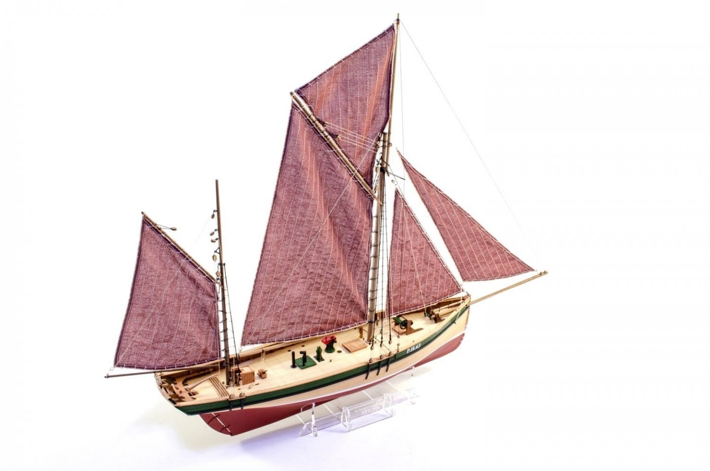
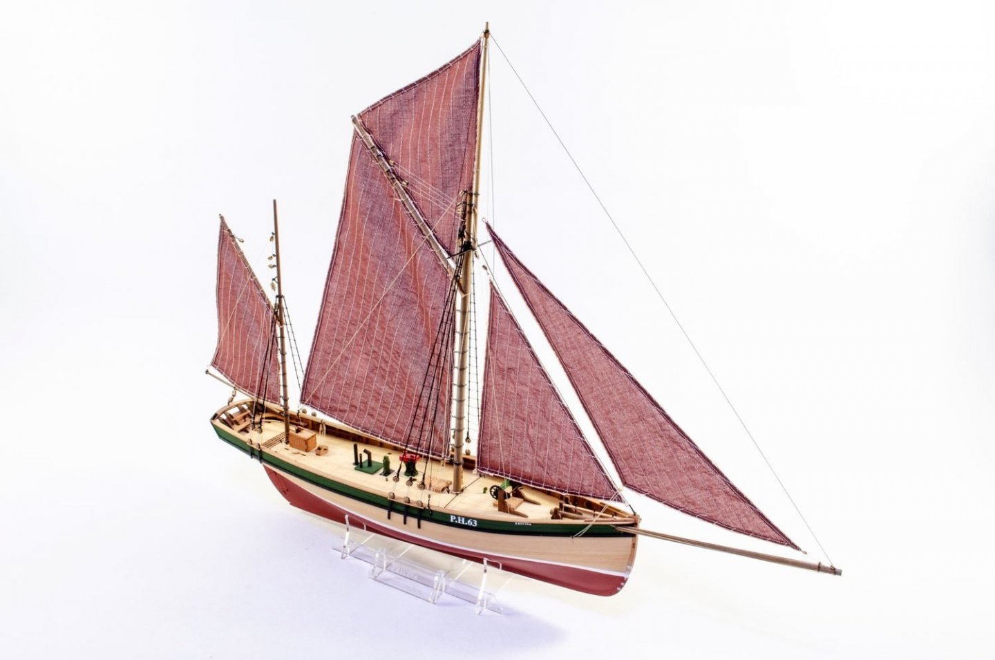
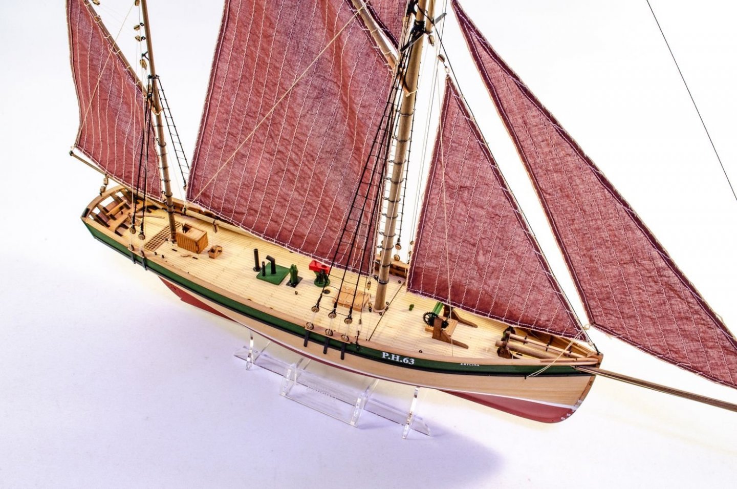
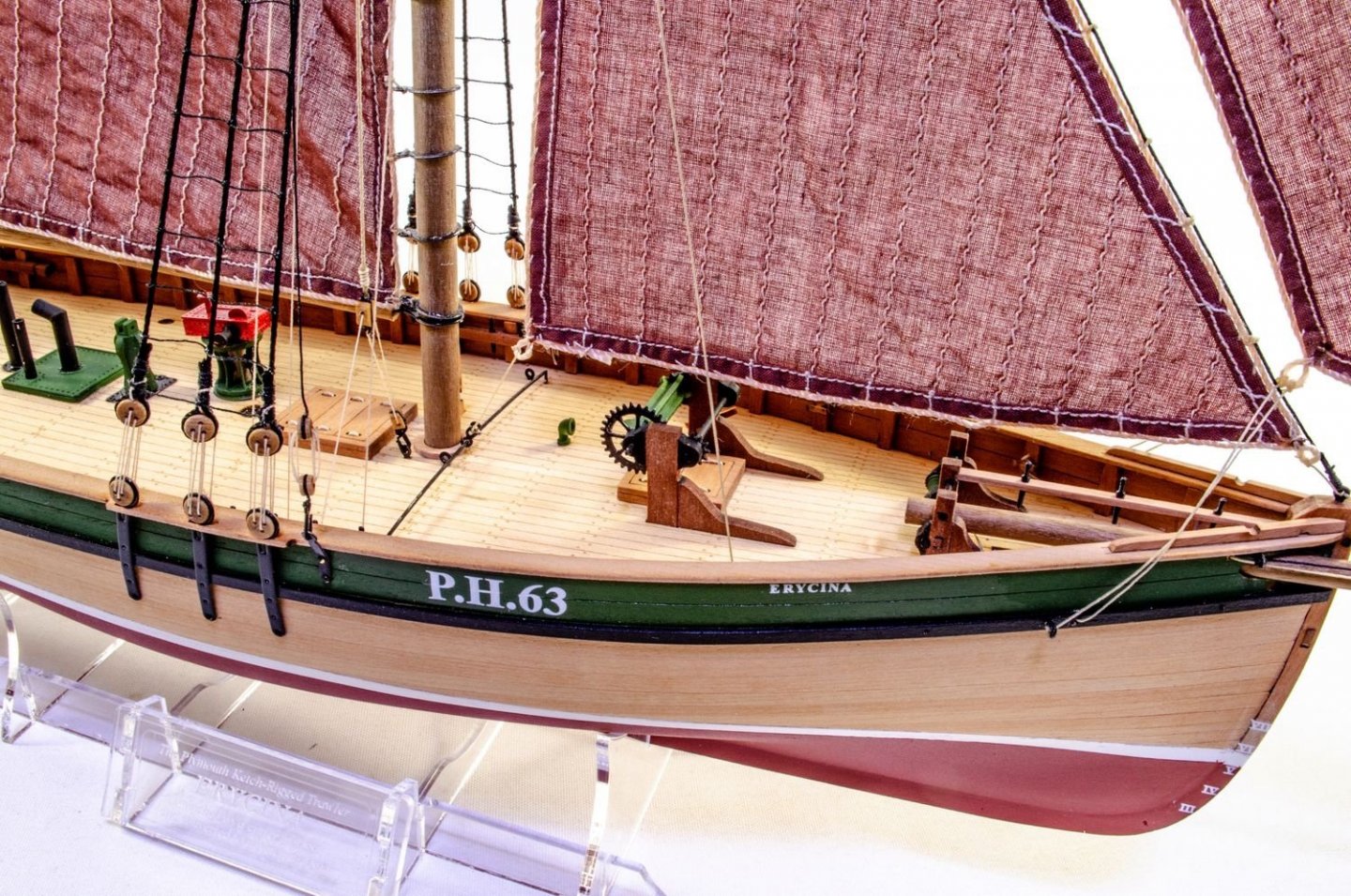
Vanguard Models have some lovely 1:64 Scottish and English fishing boats with gorgeous detail. You can look at the manuals on their site. All are aimed at the total beginner but with details that would look perfect on something more complex. Check out Erycina, Nisha, Fifie and Zulu on this page: https://vanguardmodels.co.uk/product-category/vanguard-model-kits/ Also, you can look at the build logs in my signature. All kits are planked in pear wood, as well as other details in it, plus have maple, laser-engraved decks.
-
Just get in there with some dilute acrylic wood filler, applied with a brush. Let it dry, sand then lightly re-coat. Repeat until happy 😉
- 505 replies
-
- 5
-
-
- vanguard models
- Sphinx
- (and 1 more)
-
Posting Problems
James H replied to turangi's topic in Using the MSW forum - **NO MODELING CONTENT IN THIS SUB-FORUM**
Ok, fixed. -
Can we steer this topic back to what it was, and not skirt around politics please...
-
That's looking spot on, Maurice. Don't worry too much about accidentally filling the engraved lines when painting. I did mine with a rattle can and you can still very clearly see the lines.
- 857 replies
-
- 4
-
-
- Sphinx
- Vanguard Models
- (and 1 more)
-
CAF are legitimate. In fact, we'll have a review for Parts 1 & 2 of their 1:48 HMS Granado POF on MSW very soon.
-
To be honest, I'd struggle to, any more than I did for Flirt, Duchess etc. They are all very similar in execution, especially Duchess which as the same tuck at the stern. Sphinx is no different to fair than most any other similar ship. I just have a plank I lay around at various positions to see how it meets up with the bulkheads. For the stern, curl a plank at the end and again, test the flow around the tuck etc. Out of all the models I've built for VM in the last 2yrs, Sphinx has probably been the very easiest of them to fair, probably even more so than Duchess.
- 476 replies
-
- 3
-
-
- sphinx
- vanguard models
- (and 1 more)
-
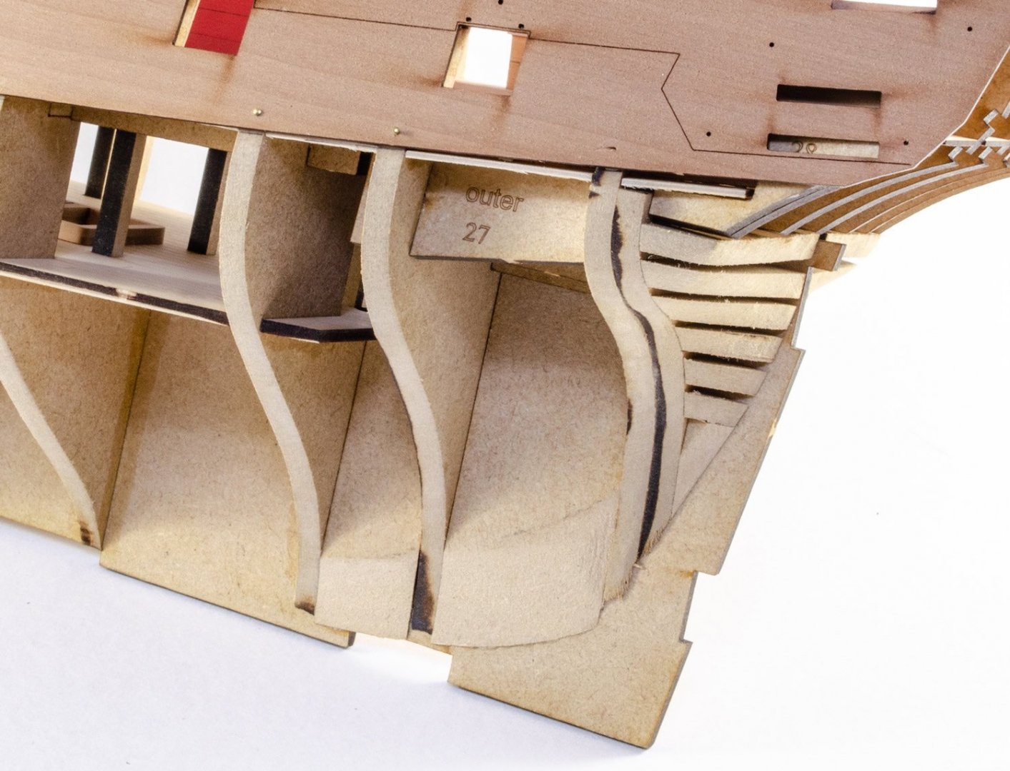
It looks like you need to fair those rear bulkheads more, without doubt. Also, I note you faired without adding the inner bulwarks first. Those bulwarks provide some real strength to the frames, prior to sanding the exterior which will inevitably reduce the thickness a little. Those bulwarks also reduce any chance of snapping or flexing of the frames. Was there a reason for your sequence? Also, this image from the instructions shows the fairing of those rear frames:
- 476 replies
-
- 2
-
-
- sphinx
- vanguard models
- (and 1 more)
-
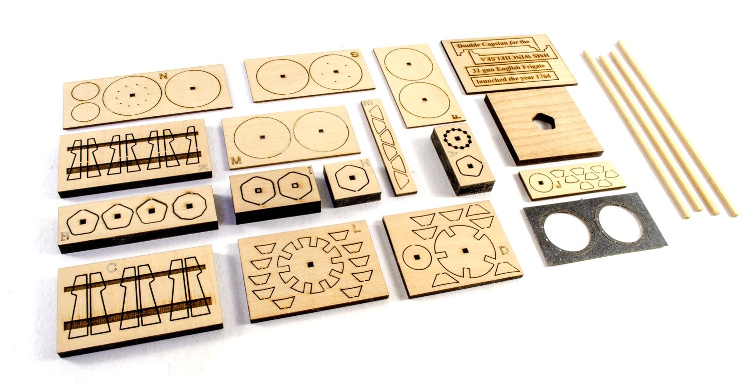
As I'm now on a brief respite from my usual stuff, I thought I'd fill in a little time with the HMS Winchelsea Double Capstan kit that I got from Syren a while ago. I'll work on this between killing aliens on my PlayStation and other important daily stuff 😁 This is a pic of the kit contents, minus the black filament that is used for the bolt heads. The first task was to gently clean up any surface scorch from the laser. Thankfully, there's very little, and I used both 320 and 400 grit paper to finish the surfaces. I'll be working on this over the next days and weeks.

-
Donation Problem
James H replied to PeteB's topic in Using the MSW forum - **NO MODELING CONTENT IN THIS SUB-FORUM**
We'll check that out. Thanks for the heads up. -
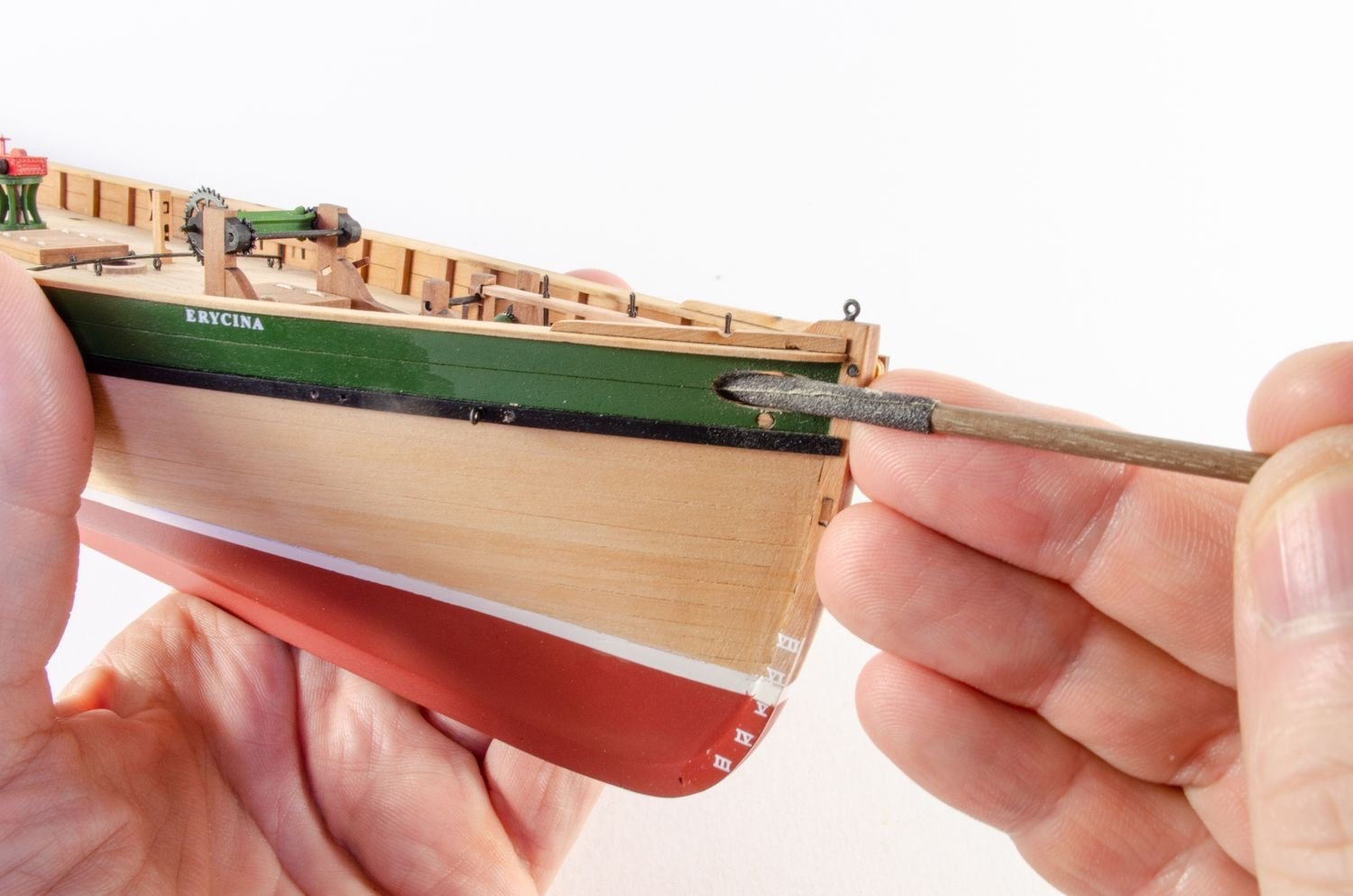
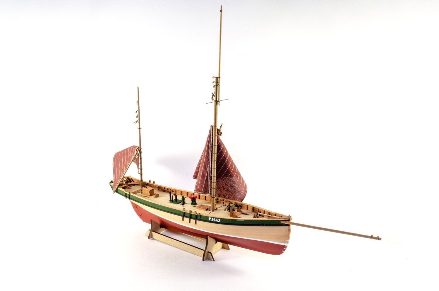
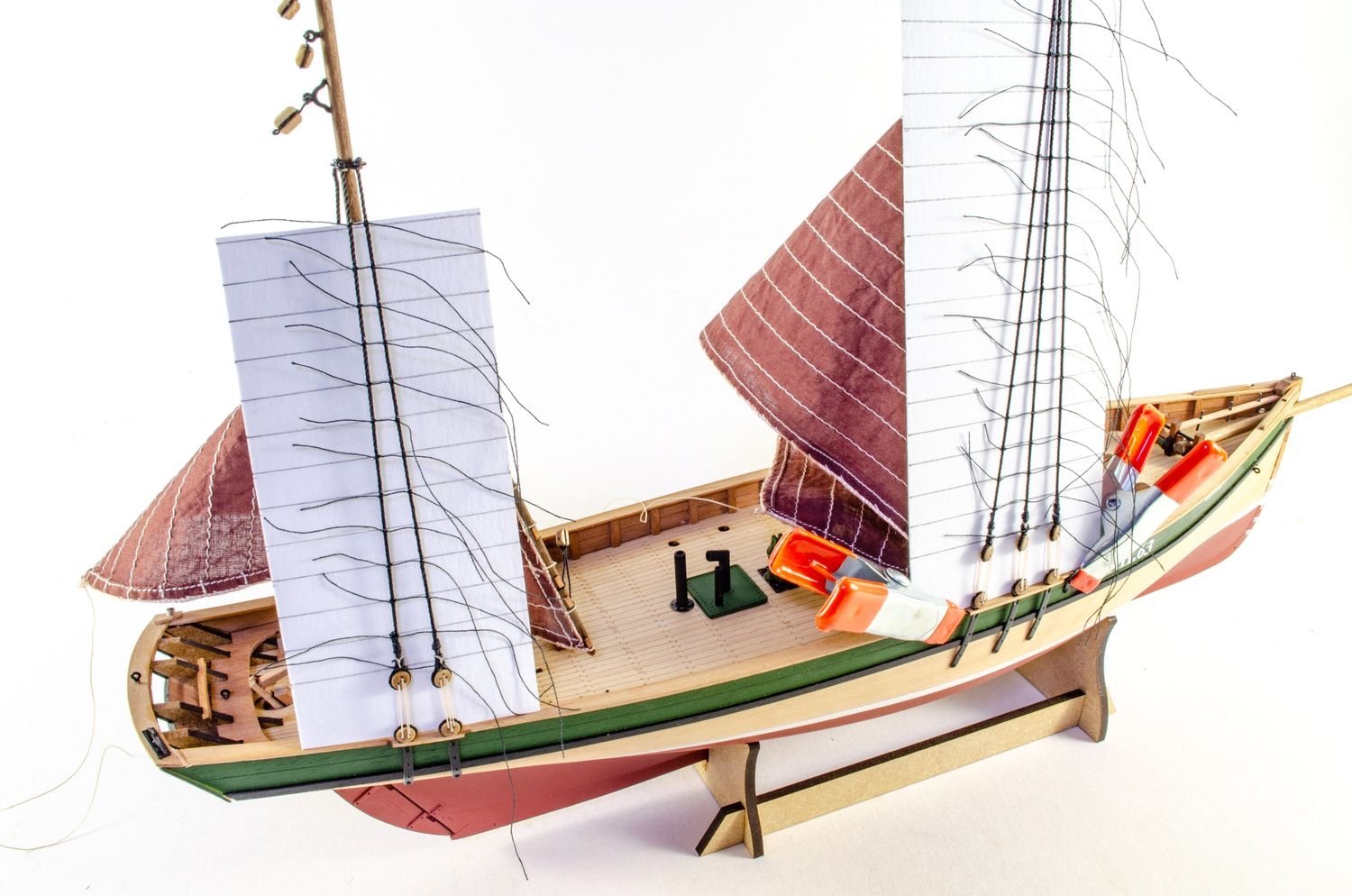
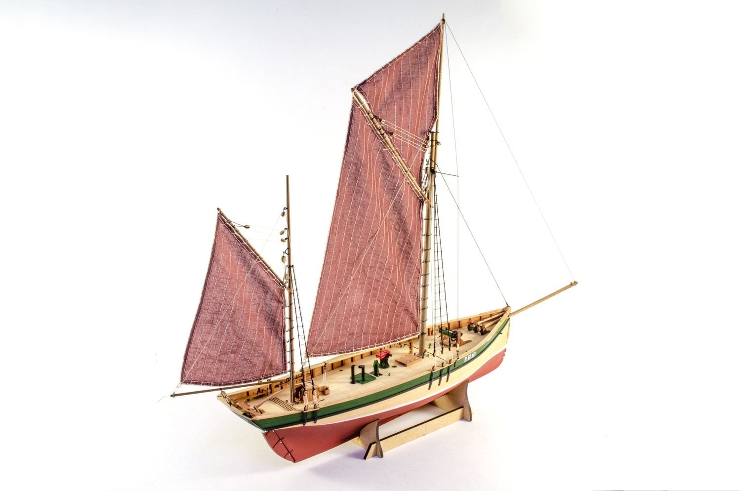
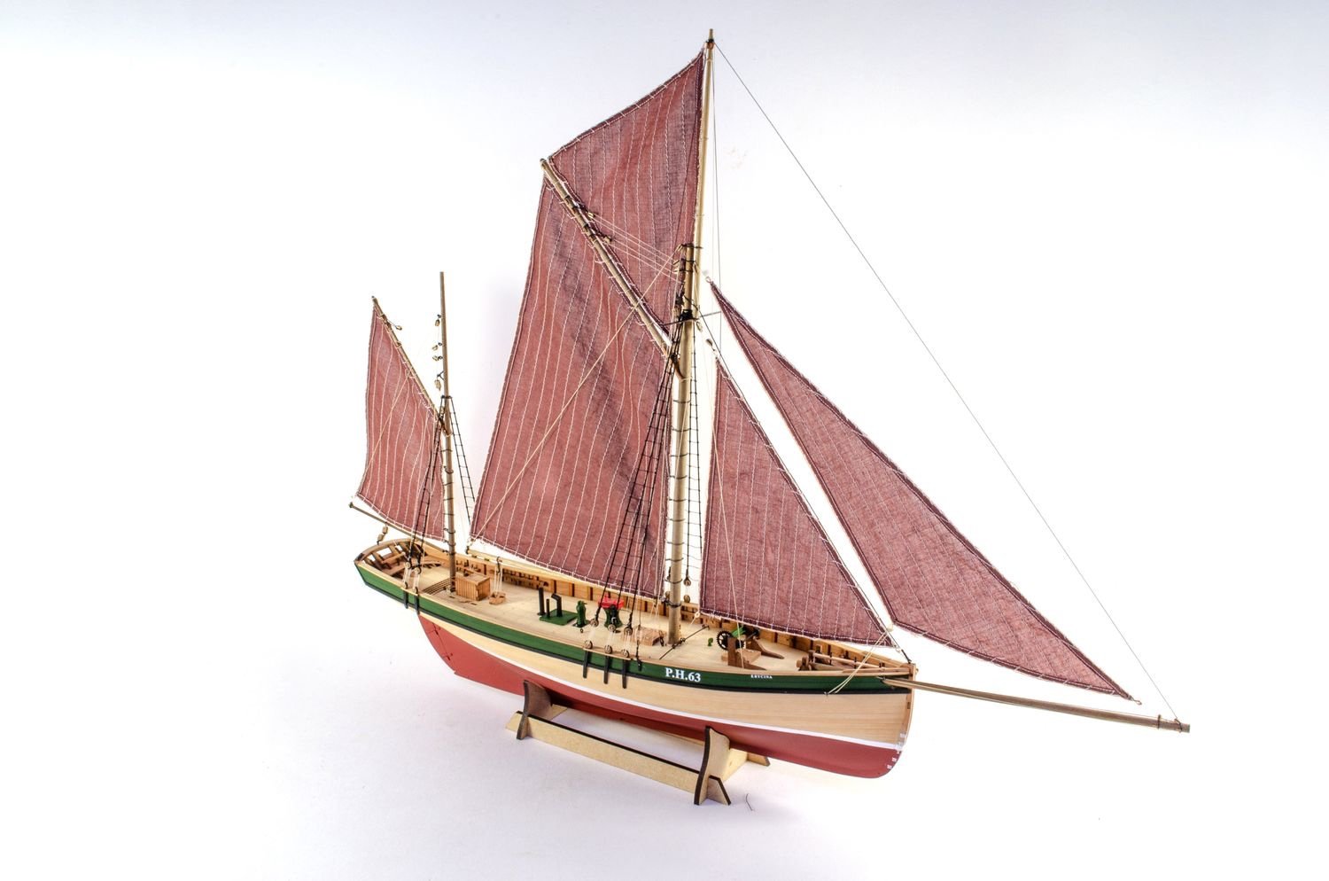
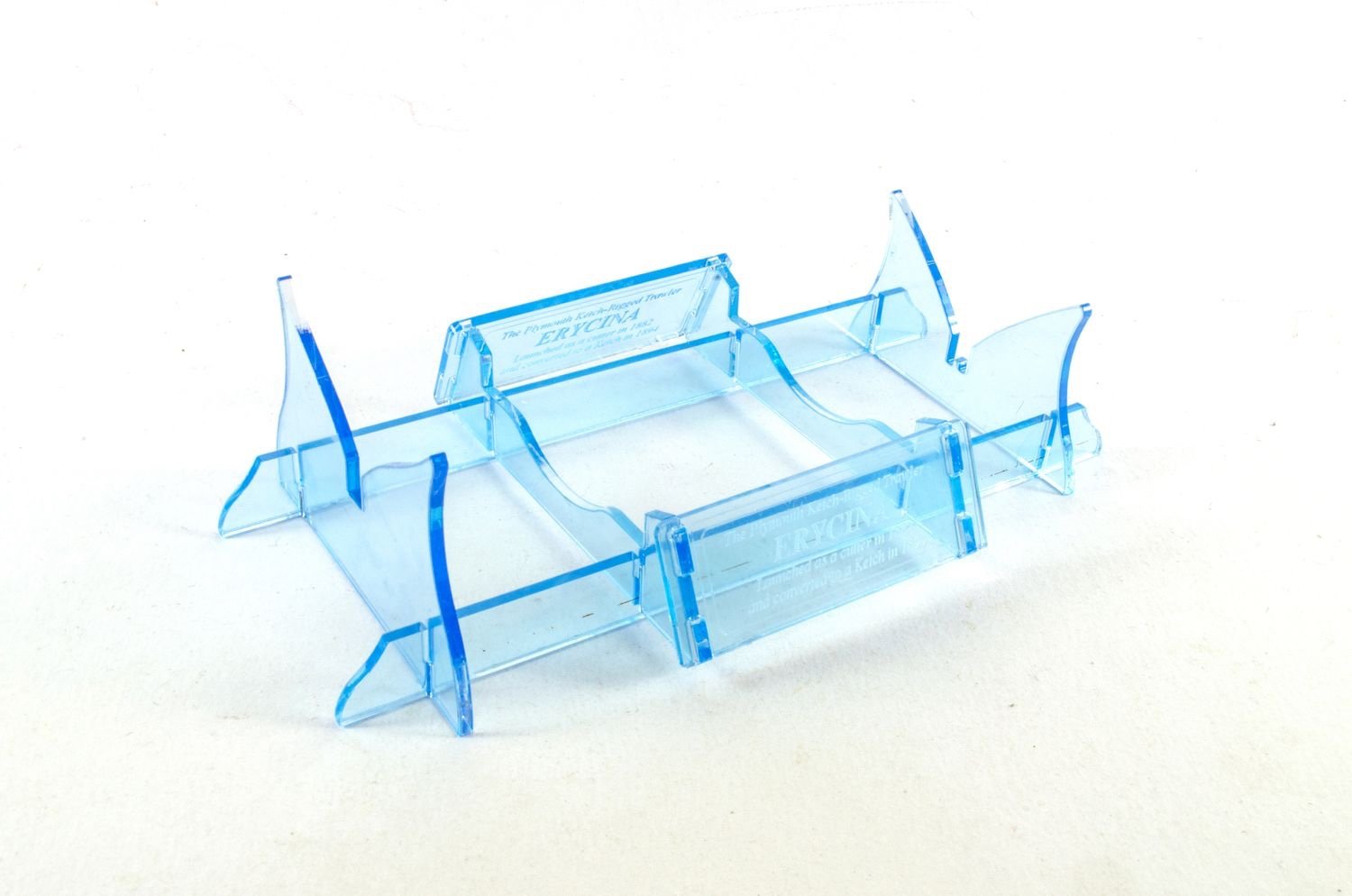
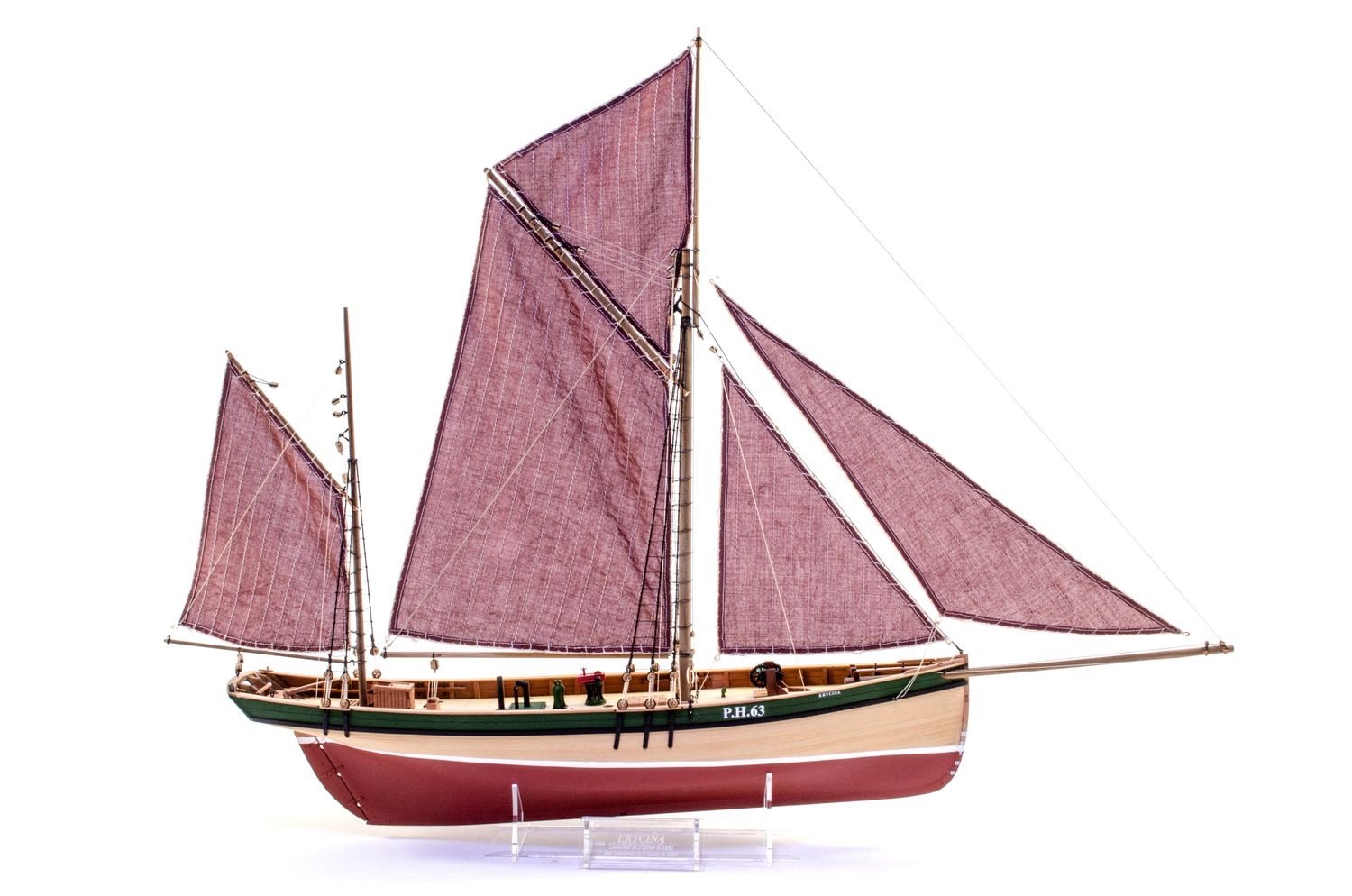
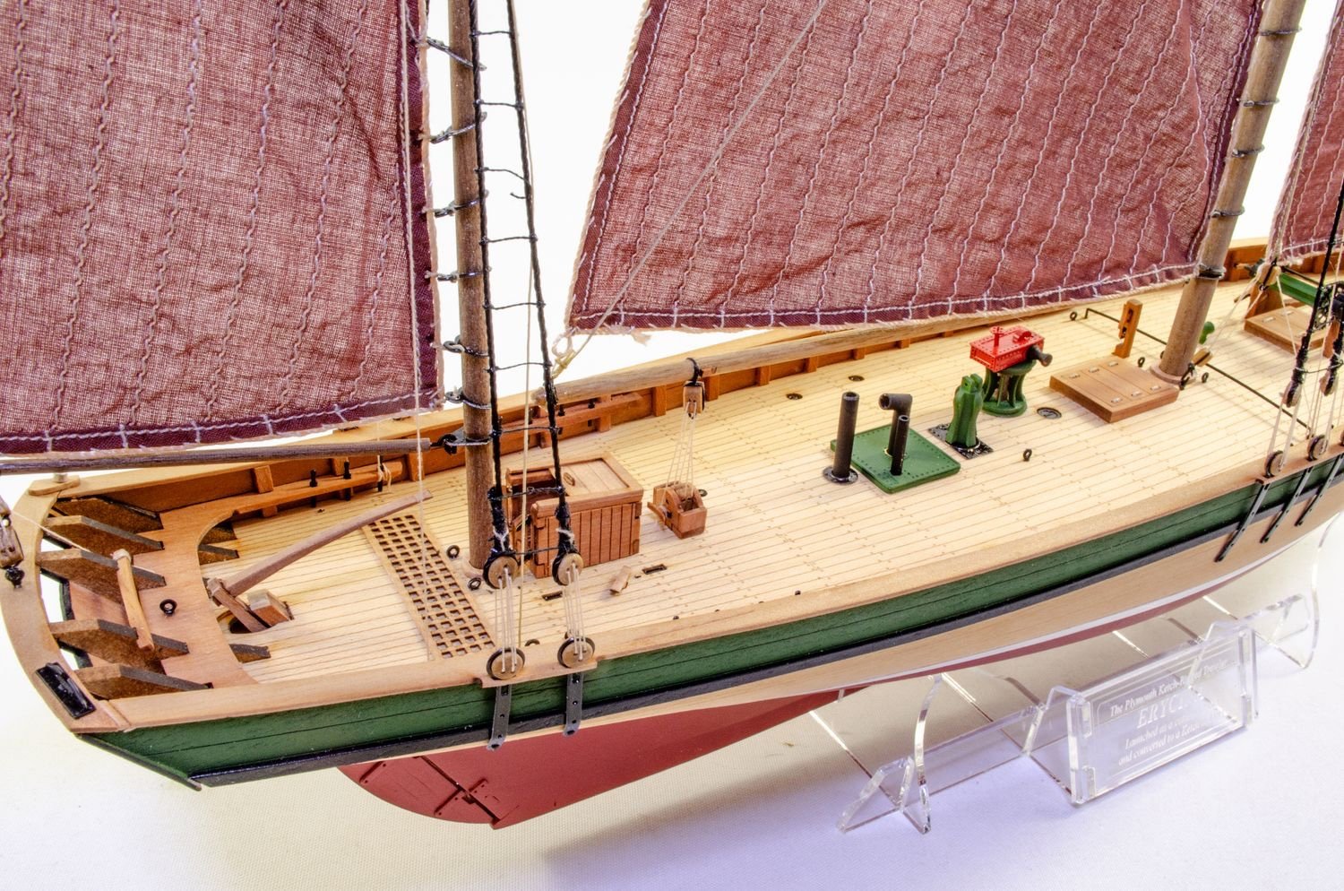
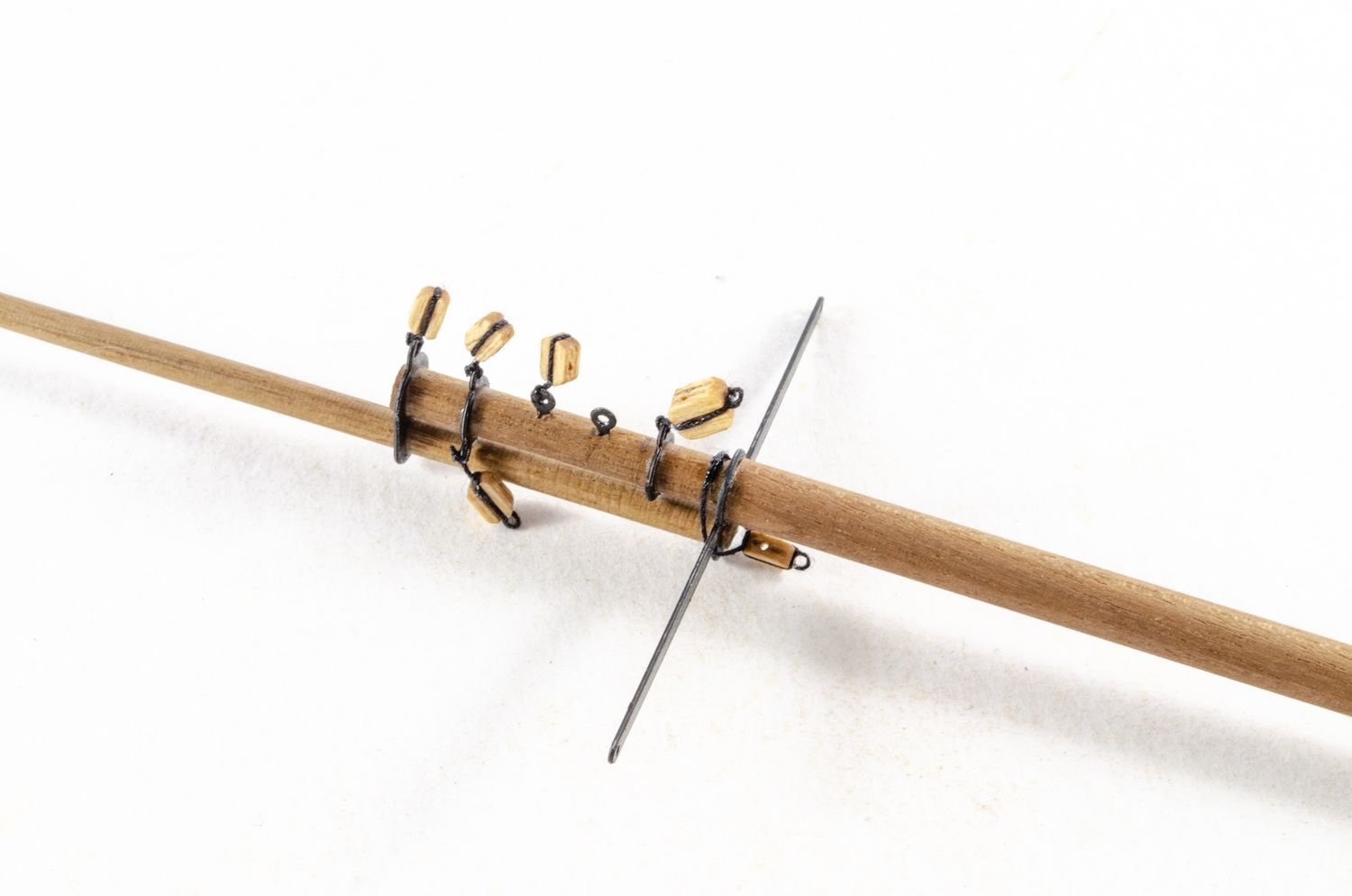
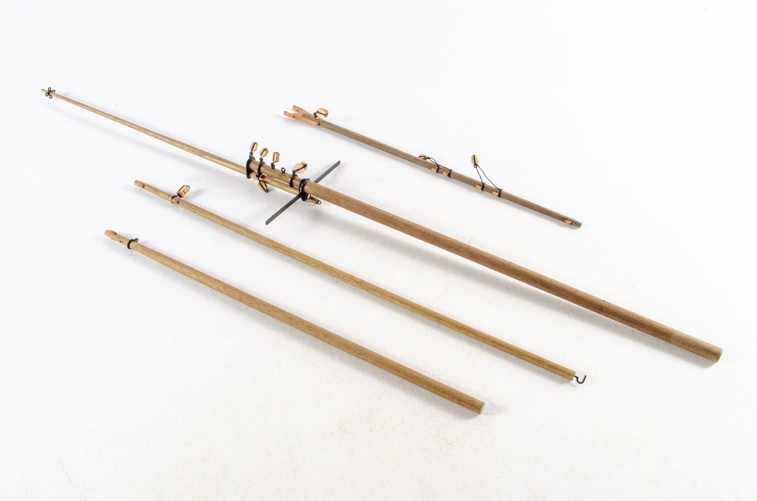
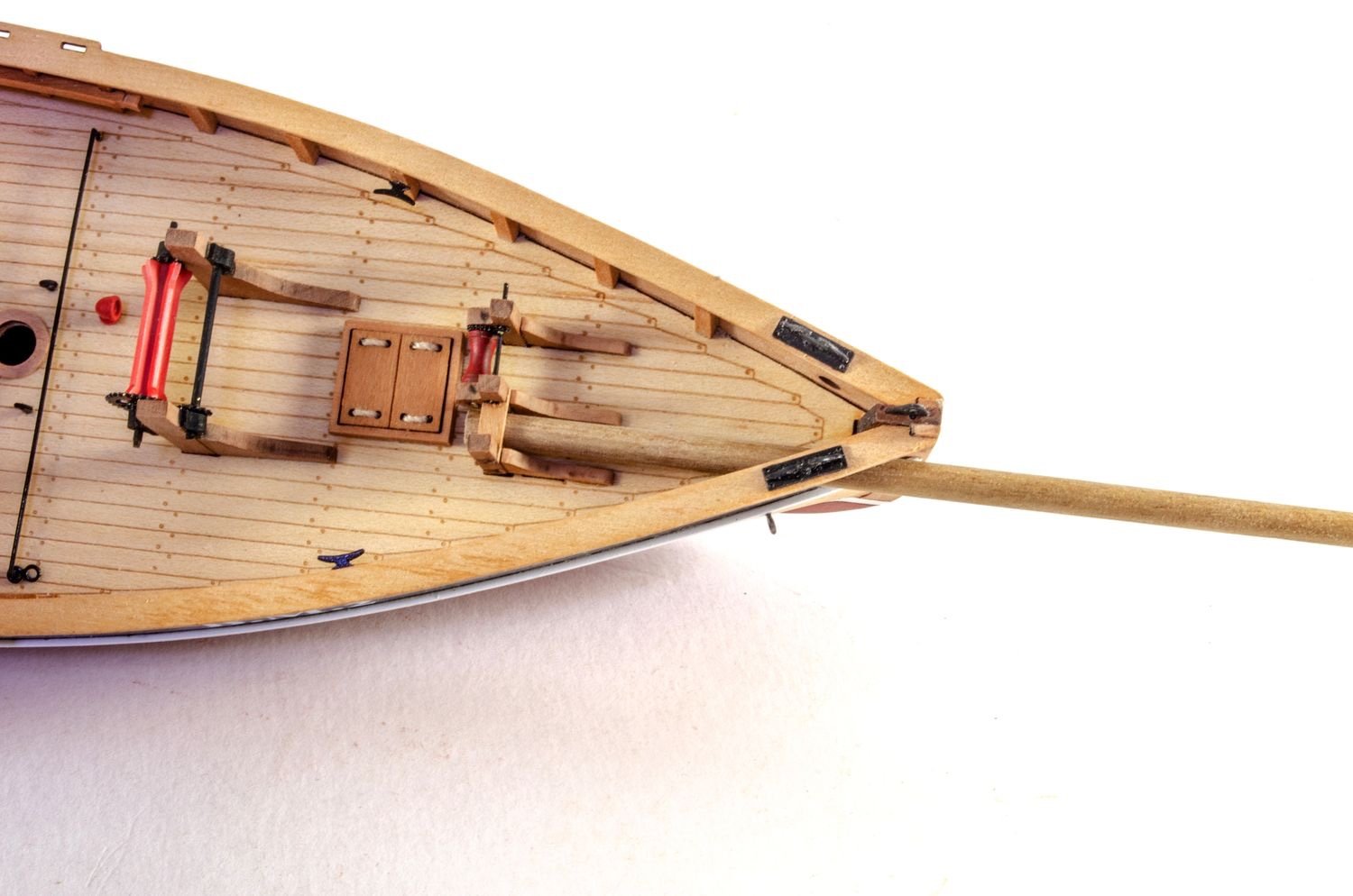
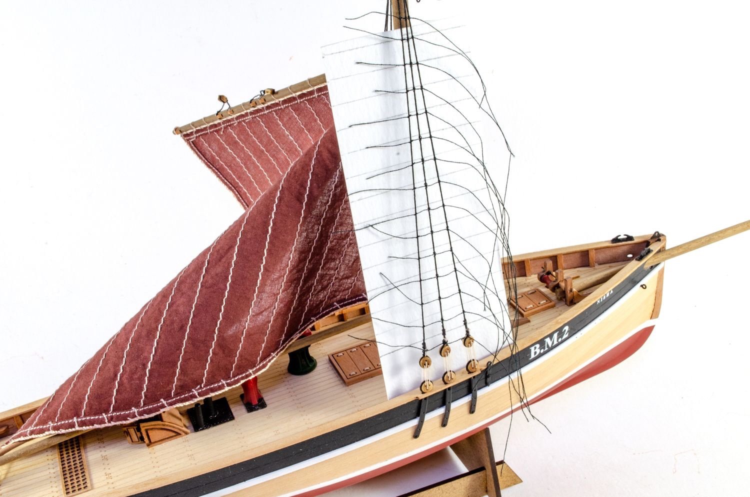
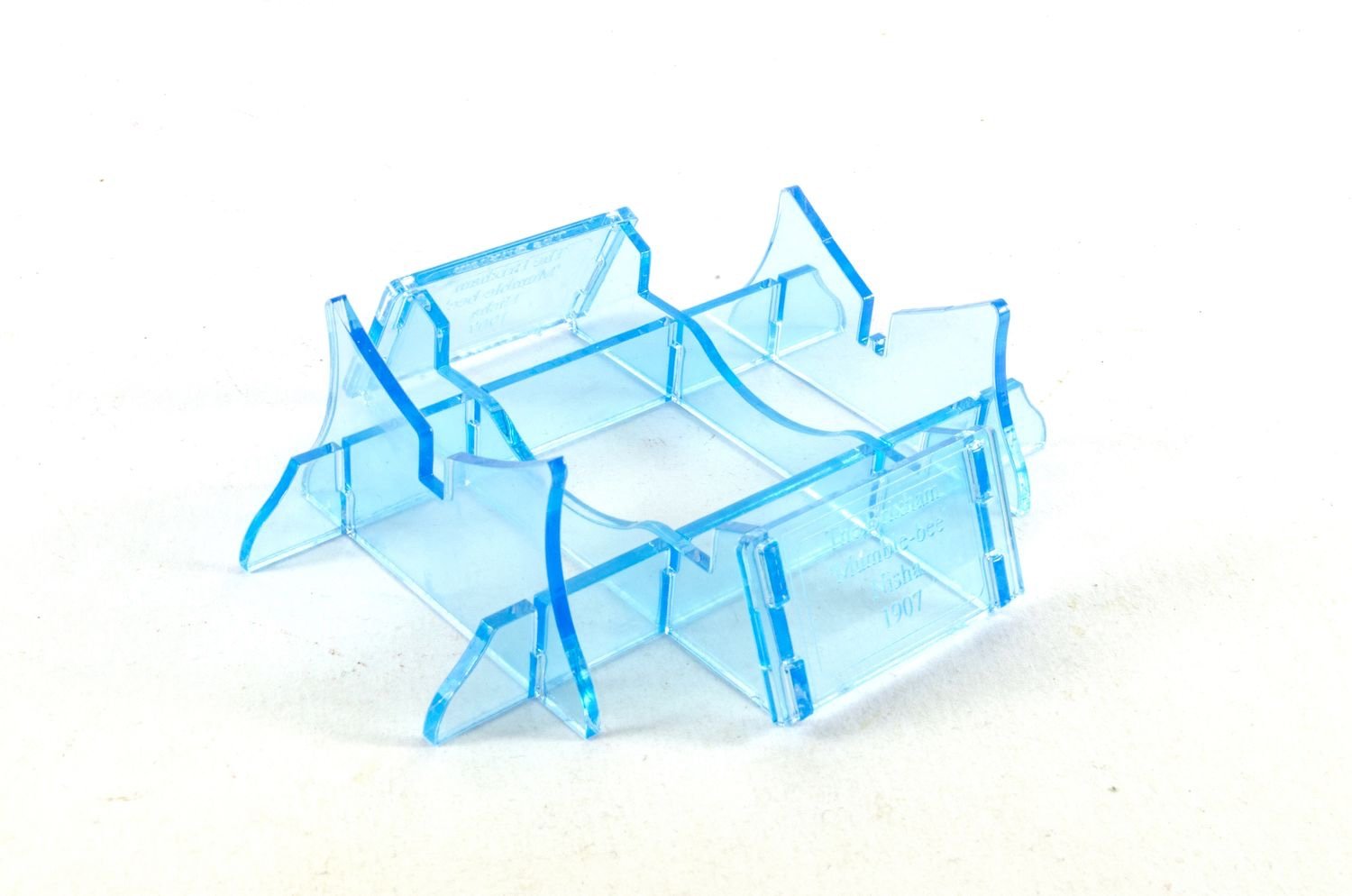
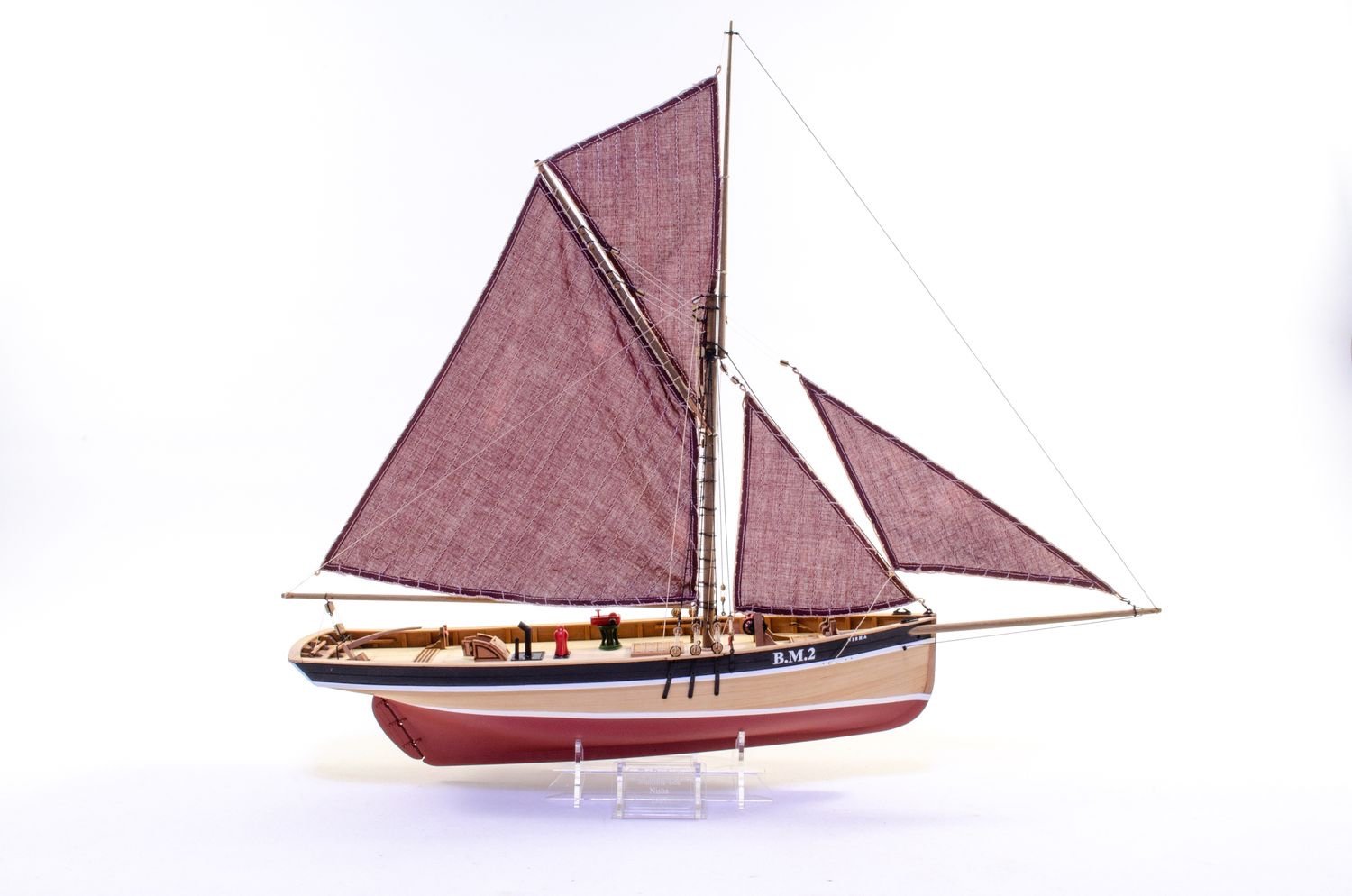
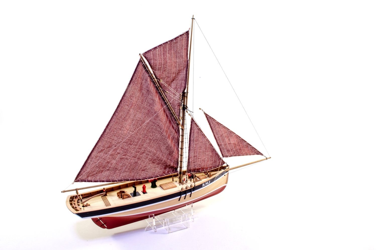
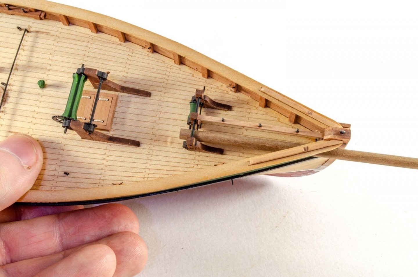
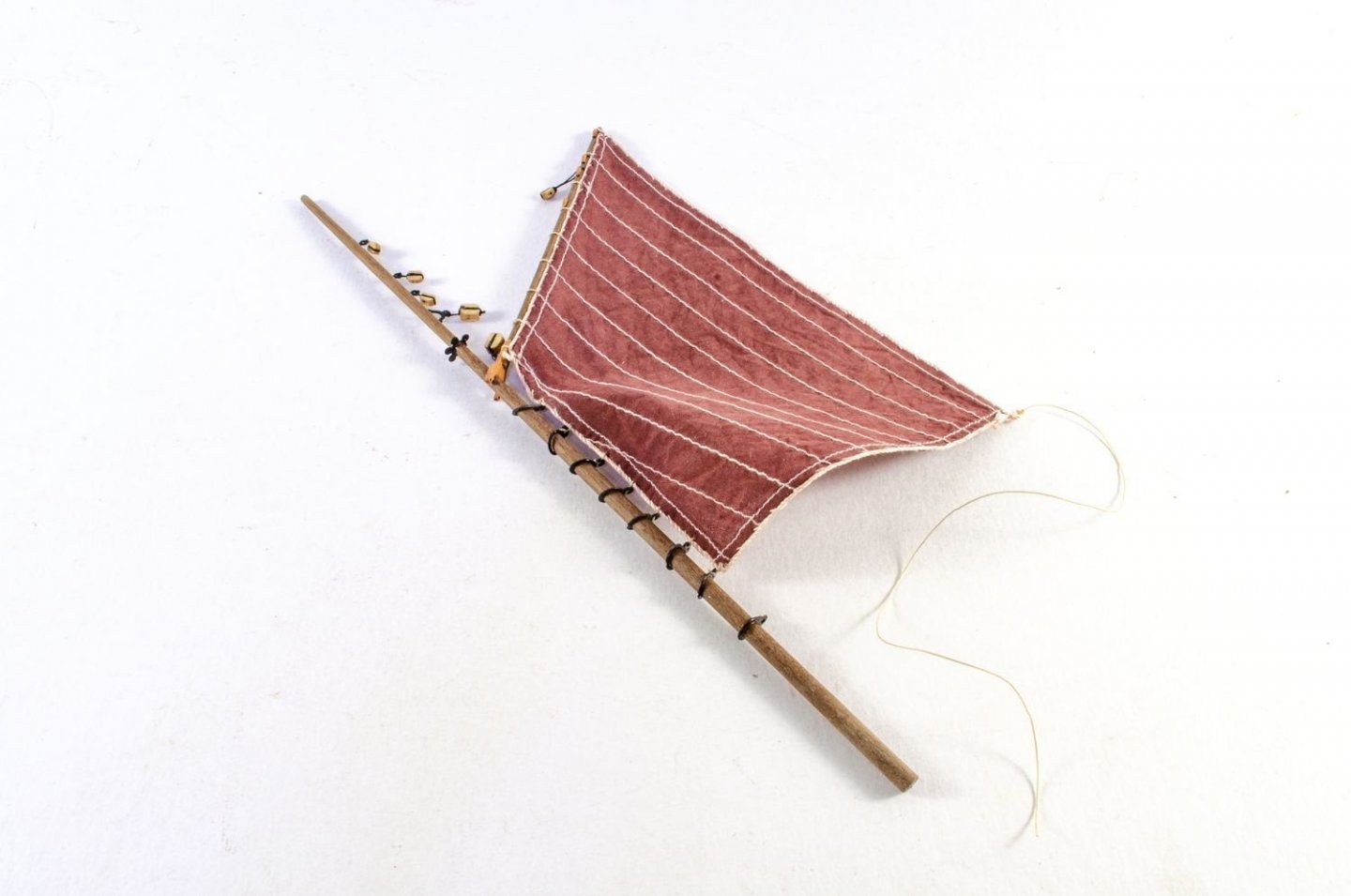
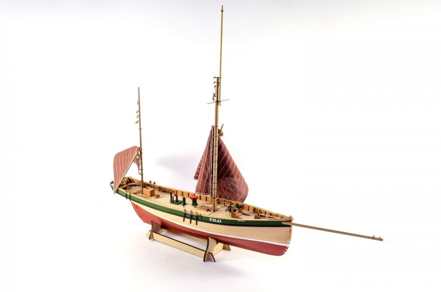
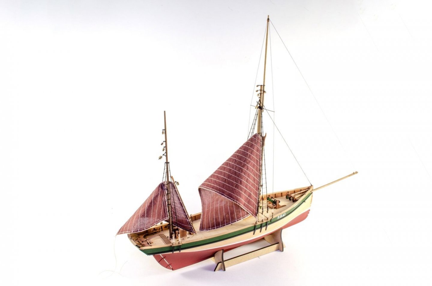
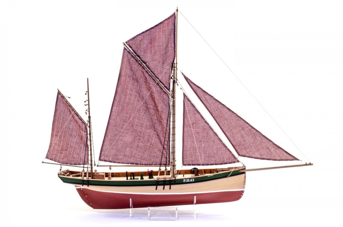
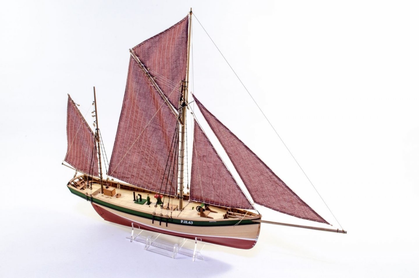
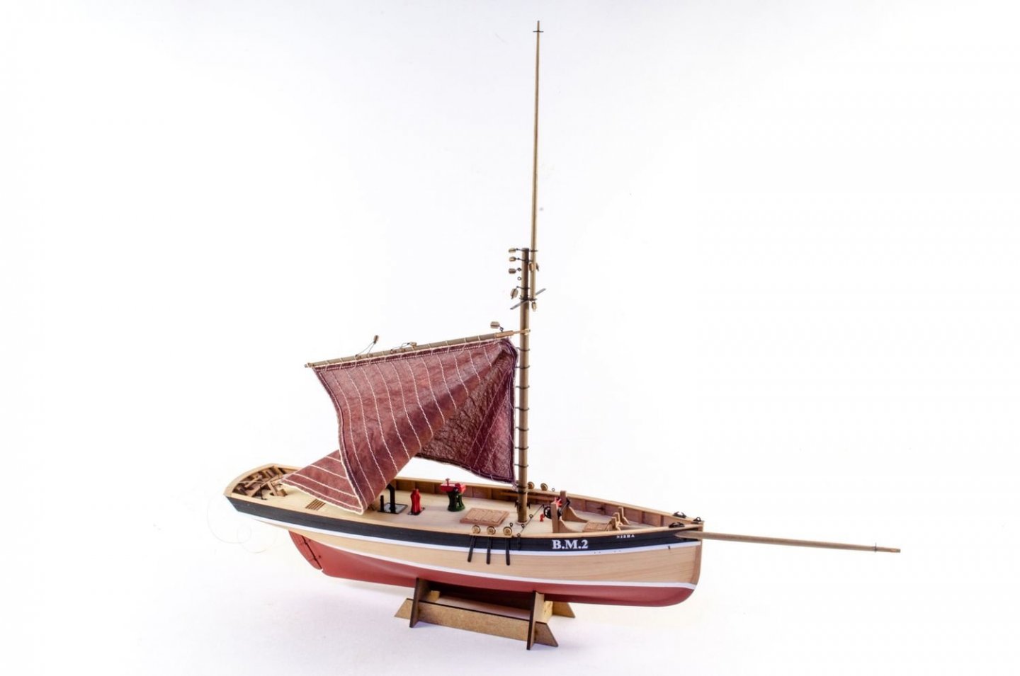
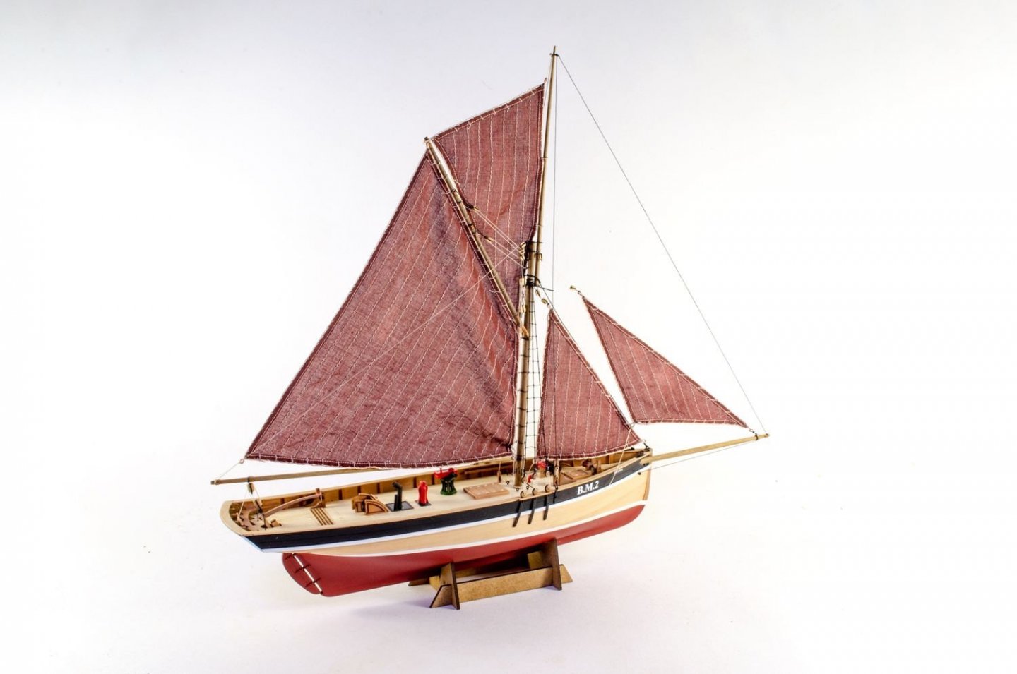
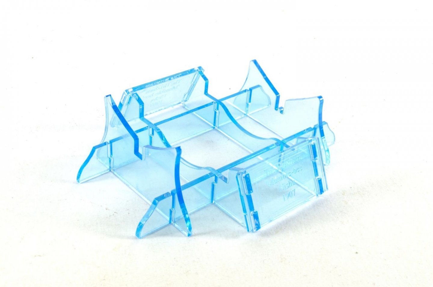
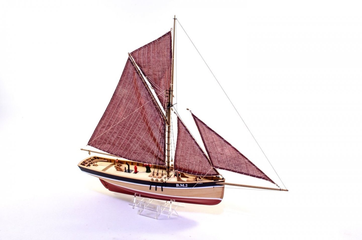
And now the swan-song for this lovely little build. These will be released within a couple of weeks. It's as close to giving birth as I can get 😆 Unlike Nisha, there are two masts to make here, but the mizzen is just a single piece of tapered dowel. The only difference between this and Nisha is that the mizzen carries another sail and also needs some simple shrouds and rats installing. To fit the bowsprit, the opening needs elongating. I used some 3mm dowel wrapped in 180 grit paper. This was tested until I got a nice fit with the bowsprit. If you buy the optional sail set, you will need to fit the sails before masting. Note that I dyed the sails in dark brown, which was quite typical for a working vessel of this period. Those shrouds and rats are so easy, as you can see. A ratline spacing template is provided on the plans, making this a whole lot easier for you. No one wants an MDF stand when the acrylic is far nicer. Here is the stand, complete with keel plug to make sure the model is properly aligned to waterline for display. And the finals! Thanks for checking in. Watch out for release very soon.


- 36 replies
-
- 22
-
-

-
- vanguard models
- Erycina
- (and 2 more)
-
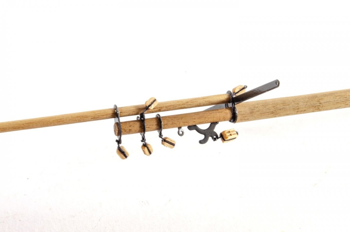
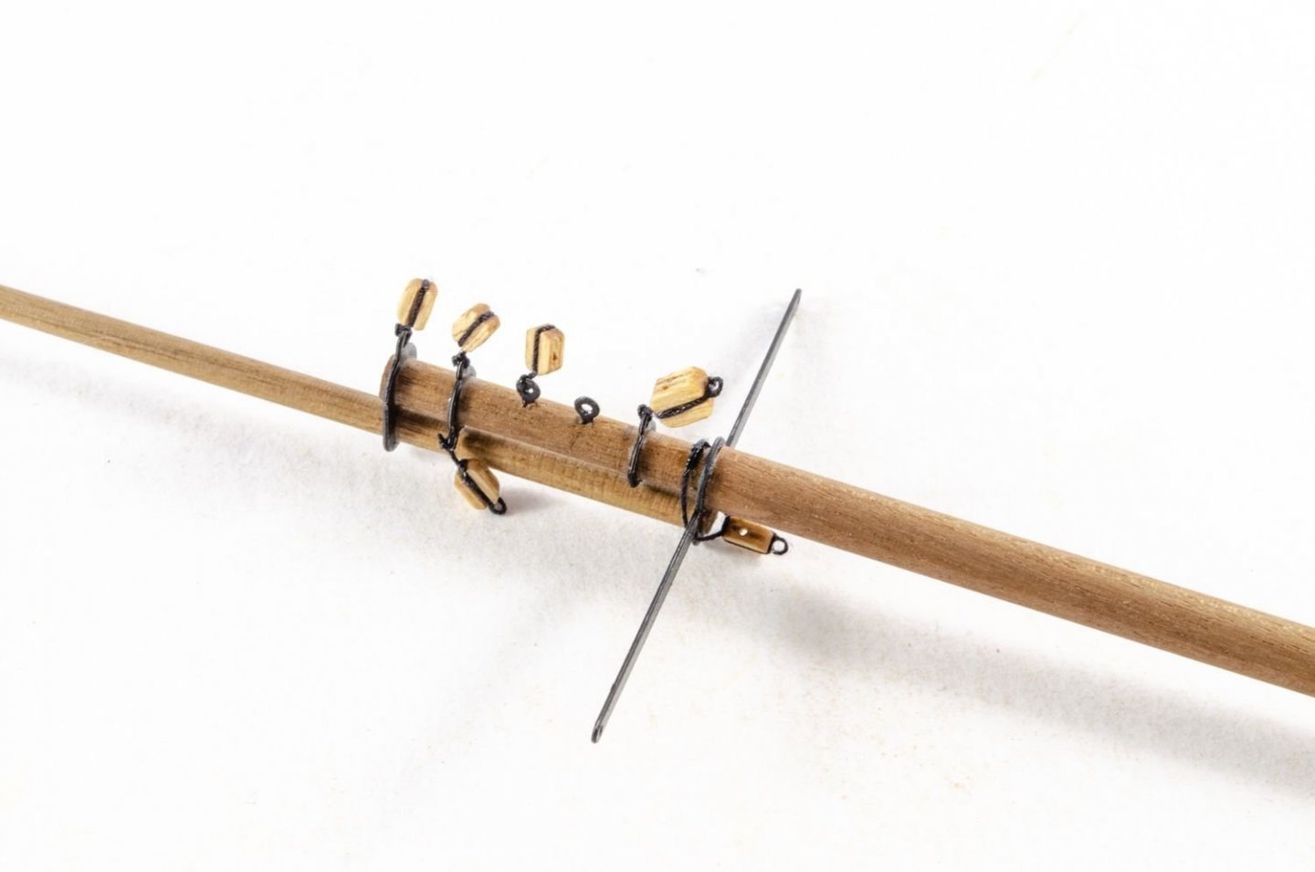
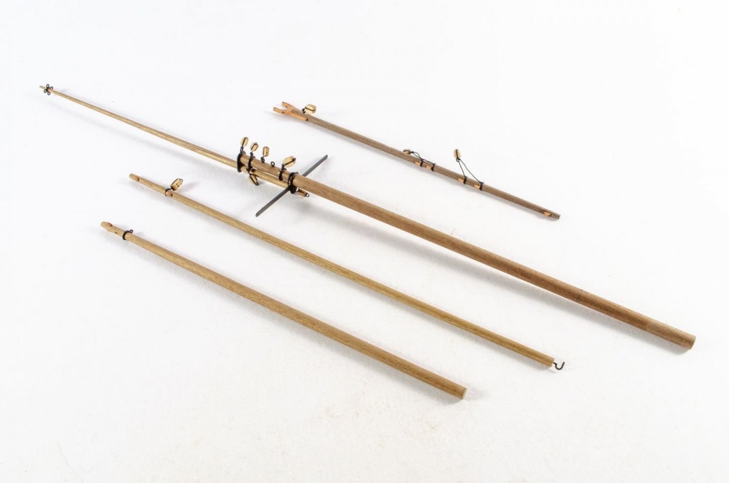
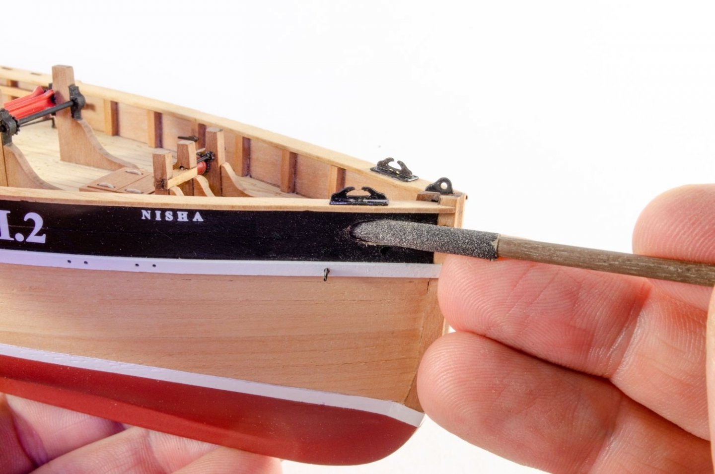
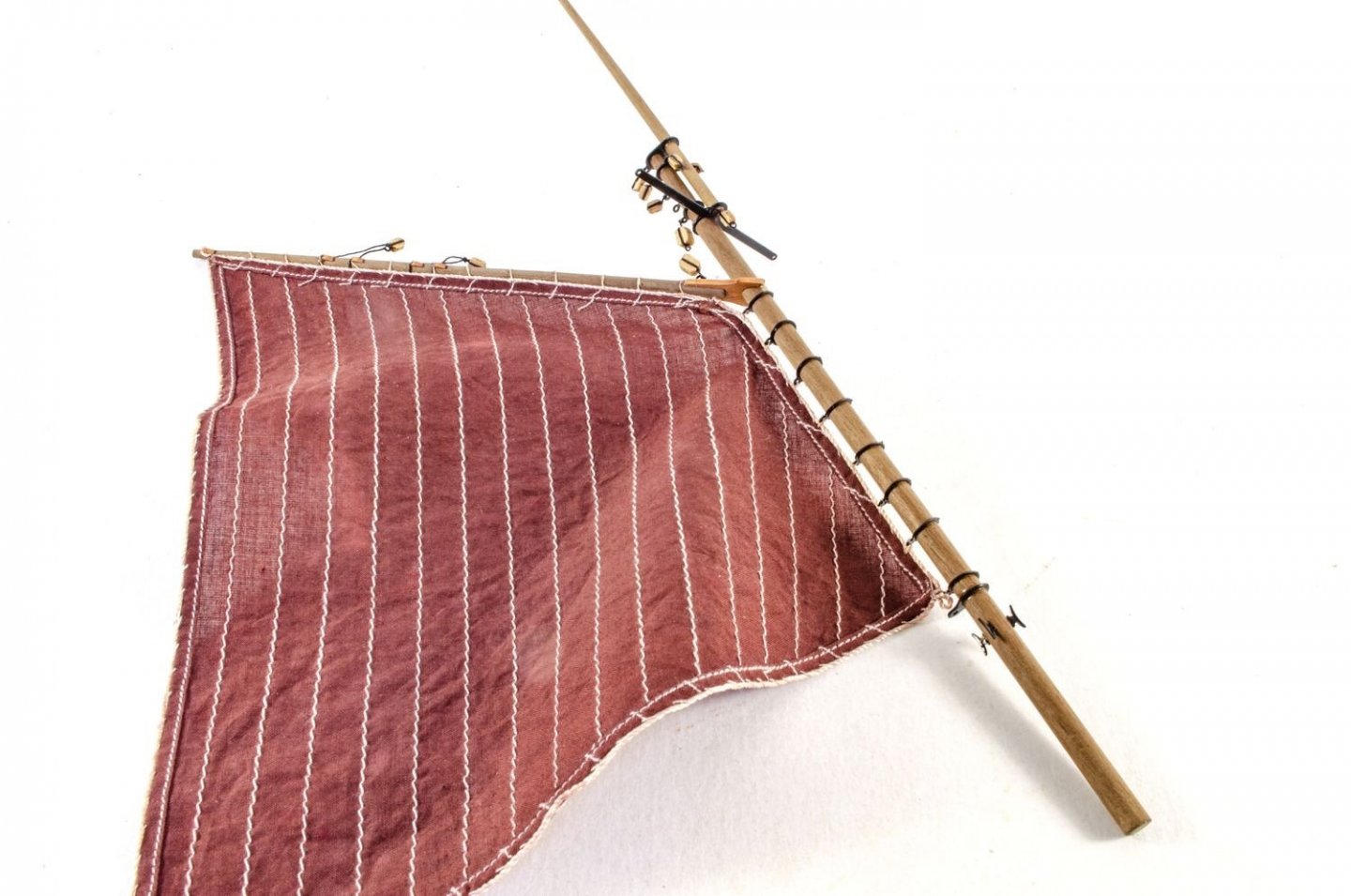
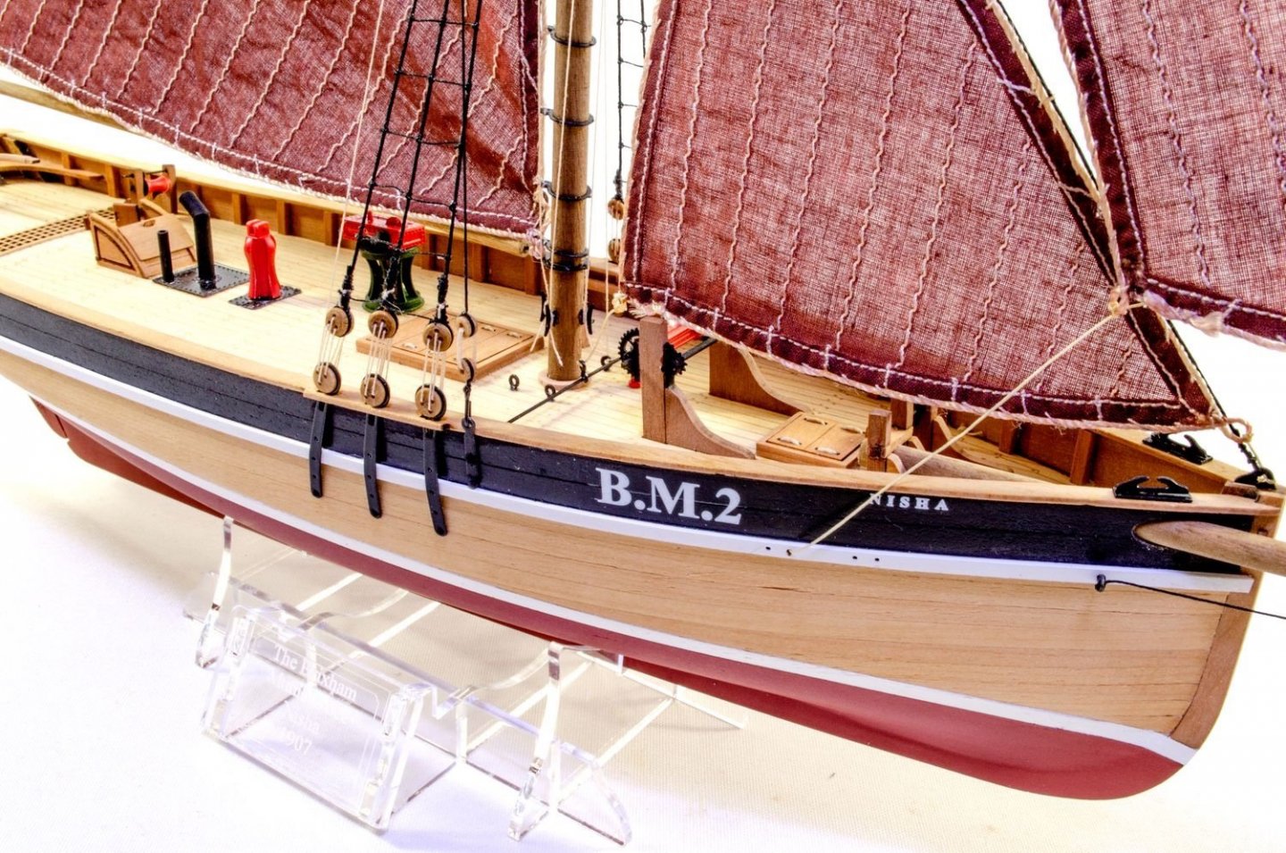
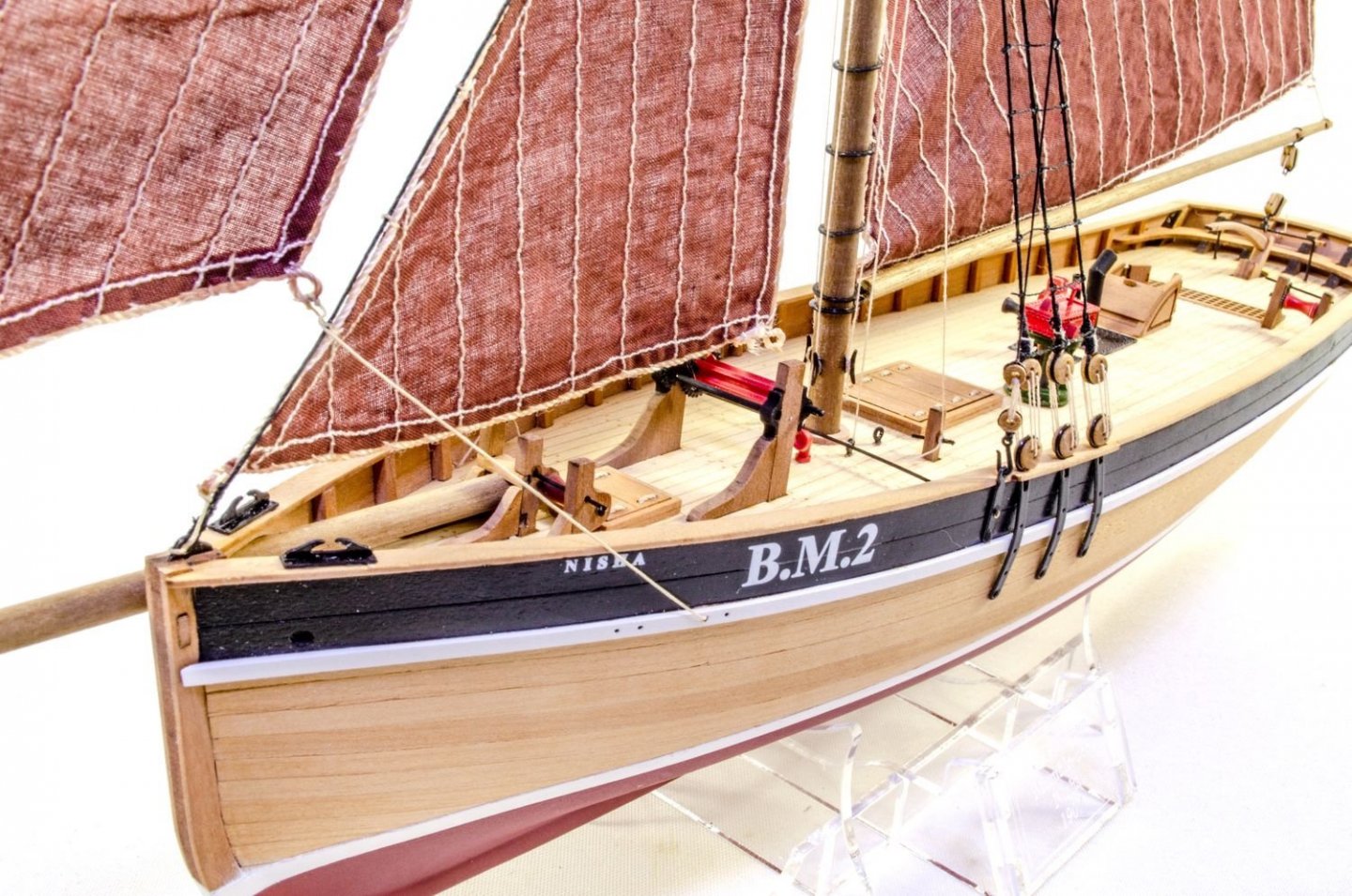
As you've possibly already seen, Nisha is complete, so here are the final pics as the kit is now nearly ready for release. Building the masts for this is so easy....as there's only ONE 😁 There is a little stepping in diameter to be done, but only a 30 minute job. The mast is then fitted out with blocks, ready for the sails to be added before masting to hull. Of course, the bowsprit opening needs elongating. I used some 3mm dowel, wrapped in 180 grit paper. Worked a treat. The sail set is optional, and I dyed this is RIT dye, using more more than I did for the previous fishers. Time to mast! Yes, there are some shrouds and rat here, but they are just so very simple and perfect for a newcomer to tackle. The plans also include a template for ratline spacing. Just paste to some card, and you're good to go. Here she is, all complete. Just the acrylic stand to build. And....my final pics! Thanks for watching. Nisha will be released within the next couple of weeks.


- 28 replies
-
- 20
-
-
- vanguard models
- Brixham trawler
- (and 2 more)
-
Not using the acrylic one? It's a million times better than the MDF 🤣
- 476 replies
-
- 2
-
-
- sphinx
- vanguard models
- (and 1 more)
-
Remember that adding any paint to the cradle at this stage risks it coming off on a painted white hull, whilst you are needing as solely a building aid.
- 476 replies
-
- 1
-
-
- sphinx
- vanguard models
- (and 1 more)