HOLIDAY DONATION DRIVE - SUPPORT MSW - DO YOUR PART TO KEEP THIS GREAT FORUM GOING! (Only 75 donations so far out of 49,000 members - C'mon guys!)
×


James H
-
Posts
6,100 -
Joined
-
Last visited
Content Type
Profiles
Forums
Gallery
Events
Everything posted by James H
-
 This one is a 3D-printed hull and has some pear parts too. Only thing my friend added was some rudder hinges, though it's possible some cartridge paper will be included for making those.
- 29 replies
-
- 3
-

-
- well smack
- Vanguard Models
- (and 2 more)
-
Not an introduction. Locked.
-
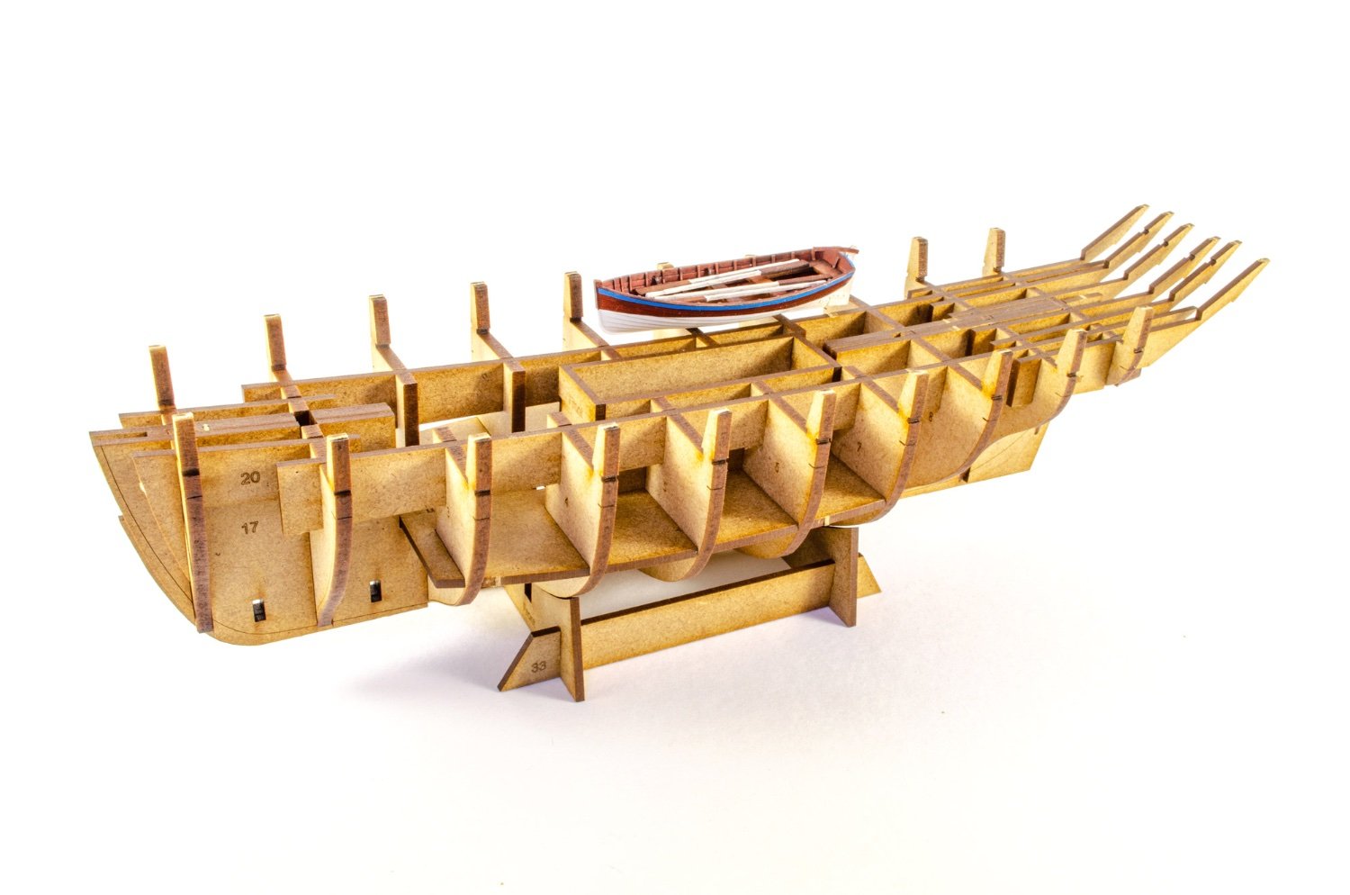
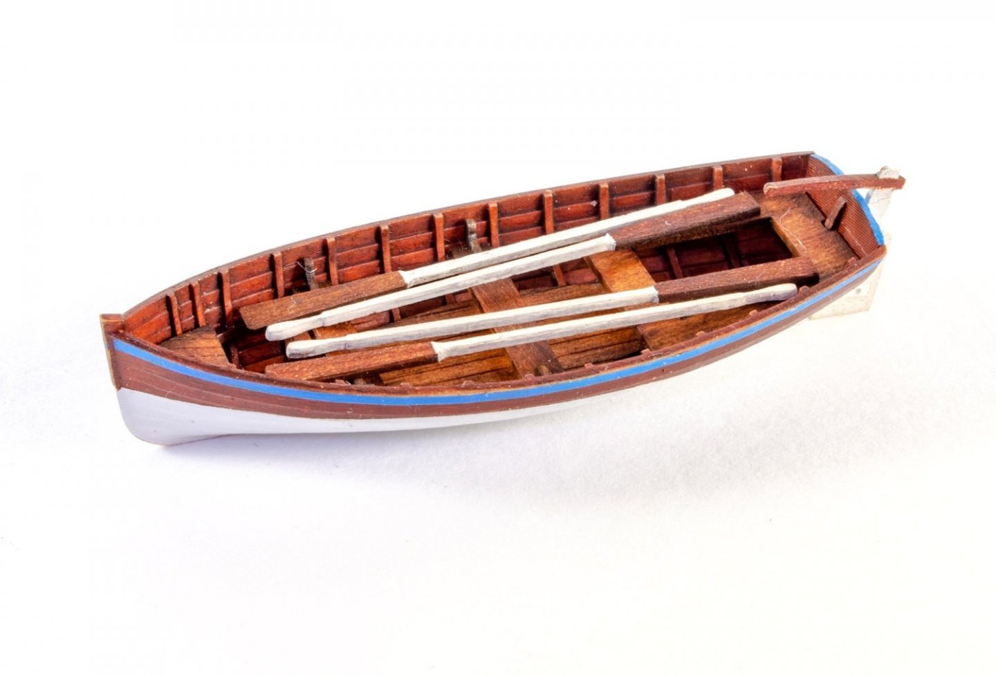
My workbench has been in some flux for a little while. While I've not been entirely unproductive, I had to wait for one of my completed builds to find its way to its new home before I could really work on anything. My man cave is a very small box room in a very small house, and the colder/wetter months stopped me spraying and sanding outside as an alternative. This delayed the release of the last two fishers as a result. I have been working on a couple of little boats for he VM range, and also Chuck's 1:48 Winchelsea capstan, which I'll return to over the next weeks. Indefatigable hasn't begun yet as I need to concentrate my efforts into this boat, plus the two ship's boats I'm working on. Indy work (guns) will resume fairly soon. Ok, excuses over. Saucy Jack: A well smack was a type of traditional fishing boat in use between the late 18th century and around 1920. It had a well amidships. The well was filled with circulated external water, which kept fish alive until delivered to land and sold. It was a modified form of a fishing smack. Between roughly 1775 and 1875, "well smack" referred to a 50-foot gaff cutter used in long-lining for cod, ling, turbot, and other bottom-living sea fish. These vessels were also known as cod boats. From roughly 1875 to 1920, they were extended to make 80-foot gaff ketches, sometimes by the cut-and-shut procedure. Some were built as new 80-foot welled smacks; some were turned into dry ships for use with ice. (taken from wiki) At the moment, all I can claim to have done is my initial dry fit of the hull frames, proving how things fit together. I've built so many of these fishers now that I can do this without referring to anything 😆. Here you see the skeleton, but with the little boat sat on it. This will be supplied with the kit, and this one has been assembled and painted by a friend of mine who hasn't dabbled in wooden/resin ships before. The interior is done with oil paints, but we'll look at this later in the build. Tonight I expect to start the proper photos for the hull instructions.

- 29 replies
-
- 14
-
-
- well smack
- Vanguard Models
- (and 2 more)
-
Lord knows how I missed this topic. You really are doing a darn fine job of her. She's looking real nice, and that ain't just an 'attaboy' either. 💯
-
Getting that hull to the point I was happy with it, took the best part of a week. Constant sanding, filling, sanding, filling, touch-ups etc. It's hard work, but it is worth the effort.
- 476 replies
-
- 4
-

-
-
- sphinx
- vanguard models
- (and 1 more)
-
She's looking real nice. Sorry I was only just alerted to this log by @chris watton. You'll find this one an easy rig too. Looking forward to seeing her complete.
- 27 replies
-
- 1
-
-
- Lady Isabella
- zulu
- (and 2 more)
-
If you are receiving updates about it, then you'll need to 'unfollow'. If that's not the case, just scroll on by and ignore the topic.
-
We've plenty of Vanguard kit logs here and you'll get some first-hand help too from others including Chris and myself. You can look at the instructions online at their site and some abridged prototype build logs in my MSW signature, below.
-
You can just run a steam iron over the sails and the creases disappear instantly. When applying dye, you'll need to scrunch them up anyway to remove any remaining dye and water before letting them dry. That's when I use the steam iron, with the sails protected between a couple of pieces of paper towel.
- 77 replies
-
- 3
-
-
- Erycina
- Vanguard Models
- (and 1 more)
-
She's currently sat under my bench, staring at me and needing some work doing!
-
New 1:48 HMS Endeavour out later this year
James H replied to James H's topic in Wood ship model kits
As soon as we have it -
Most difficult? Has she tried an Aeropiccolo kit?
-
That really is coming together really well. The deck is quite a perfect fit when located into the slot at each bulkhead ear. Sounds like you handled that nicely.
- 32 replies
-
- 1
-
-
- Nisha
- Vanguard Models
- (and 1 more)
-
As this is a VM-product topic, you'll now be able to check out the link for the new, more refined 22ft cutter hull. On the site right now! 😉😚
-
No changes have been made to MSW whatsoever, except for a cache setting in our Sucuri panel, which is now reverted. Again, clear cache/cookies. I suggest if you use an old bookmark to access the site, remove it and create a new one with a clean history visit.
-
All I can suggest for this is you clear cache/cookies and force refresh the site. I have no other answers, but doing all those should fix your problem.
-
Check my response above.
-
Try force refreshing site. I also just cleared cache on site.
-
I've also cleared system cache too, just to be on safe side.
-
Force refresh the site.
-
Error code 200
James H replied to Blue Ensign's topic in Using the MSW forum - **NO MODELING CONTENT IN THIS SUB-FORUM**
Ok, I've tried, unsuccessfully, to replicate an error. If you have had this problem, please can you PM me only with the following information, as it makes it easier than trawling through one large conversation: 1. How many photos did you last upload to get the error? 2. How long have you experienced this error for? 3. What image format are you uploading (jpeg, jpg, JPG etc.)? 4. Are you experiencing the problem on UPLOAD or after, when you click the SUBMIT button? Please don't supply any other info unless you think it's relevant. I'm going to lock this topic now as this is the only way to look at data from individuals about this problem. -
Error code 200
James H replied to Blue Ensign's topic in Using the MSW forum - **NO MODELING CONTENT IN THIS SUB-FORUM**
Yes, but does this, from memory, go back further than early December? -
Error code 200
James H replied to Blue Ensign's topic in Using the MSW forum - **NO MODELING CONTENT IN THIS SUB-FORUM**
One thing is for certain, nothing has actually changed here with regard to software updates since December 8th. Are these problems from that point or going back way further?