HOLIDAY DONATION DRIVE - SUPPORT MSW - DO YOUR PART TO KEEP THIS GREAT FORUM GOING! (Only 75 donations so far out of 49,000 members - C'mon guys!)
×


James H
-
Posts
6,100 -
Joined
-
Last visited
Content Type
Profiles
Forums
Gallery
Events
Everything posted by James H
-
 It's no biggie. You can (possibly) extend lower counter, or scrap it and build from planking strips.
 -
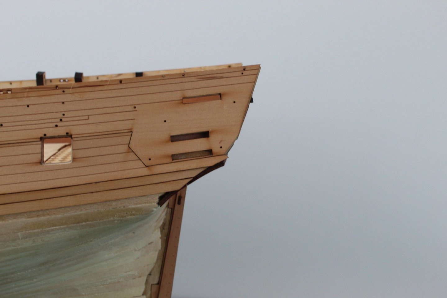
It definitely needs to be higher. Approx 2mm above height of bulwarks. There's a note in the instructions about this and the need for the lower counter to be in the correct position.
-
That's a real nice appraisal/semi-review. Thanks for posting that!
-
I used the holes on mine, and also added more, so don't worry about it. A lick of filler in each hole and a 2 second sanding is all it needs to totally hide them. Remember though, some holes are for scuppers.
-
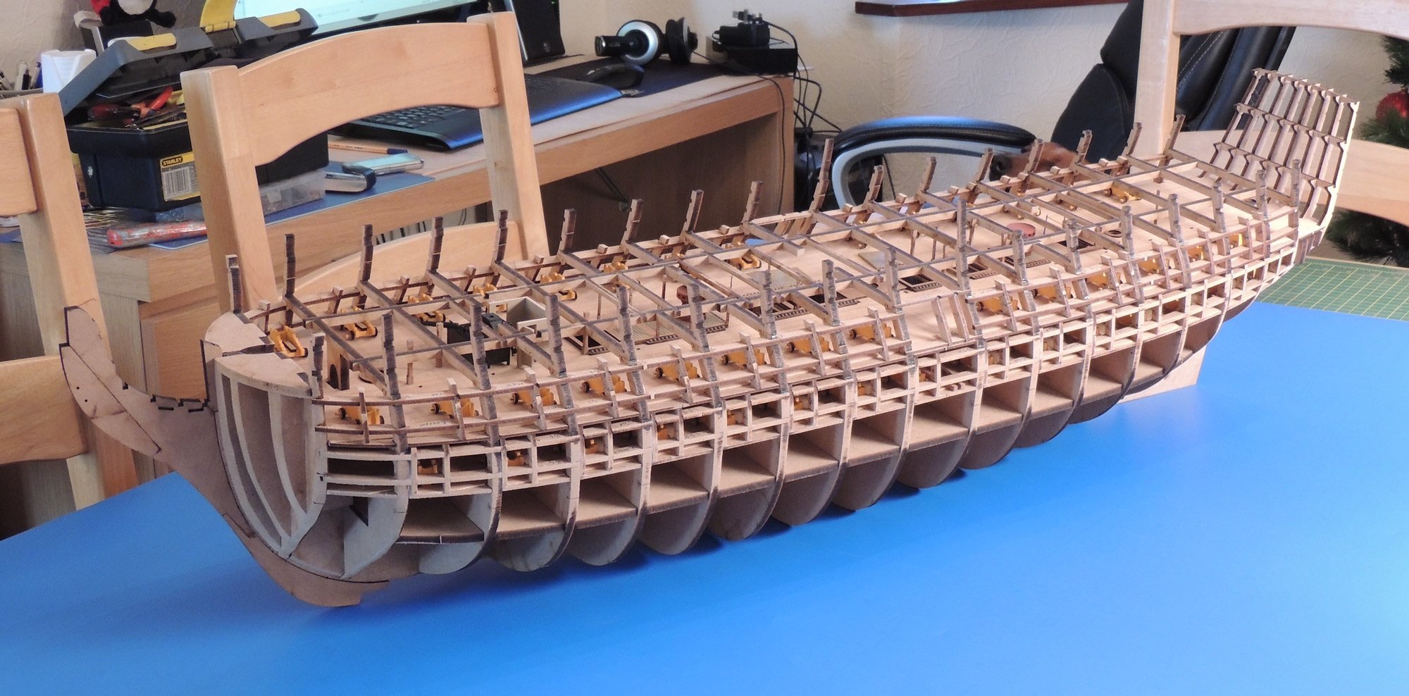
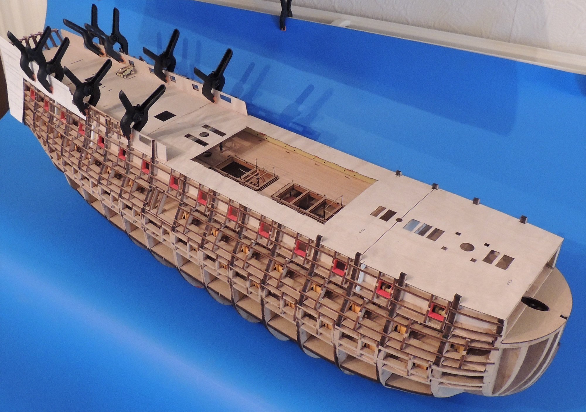
At this stage, I envisage it being new year before any further work can start. That's fine with me as it gives me a small break after my Vanguard Models stuff, before I dive back into this. I was looking through my files tonight and found 3 pics that Chris did of the original prototype. I'm not sure if these have been seen before, so I'll add them to my log so you can see what to expect as this progresses.


-
You're wrapping that around a compound curve, and there are small holes to allow you to pin it to the hull while it dries out. Alternatively, you can use elastic bands or tape to hold it around the the hull curve that affects the narrow width of the part while it dries.
-
That looks really nice!
-
Focus Stacking
James H replied to Dennis P Finegan's topic in Photographing your work. How to do this.
That's quite possible. What would be the next step from a D5100 that would include such a feature.....but won't bankrupt me? The D850 you mention? That's probably more than I can stretch to. -
Focus Stacking
James H replied to Dennis P Finegan's topic in Photographing your work. How to do this.
I need to see if my D5100 does this. At the moment I'm doing the photos manually and stacking in Photoshop. -
I'm building the prototype for the manual. This kit has been knocked back by over 12 months because of Covid. Italy was particularly badly hit to start with and all Amati's operations were put on the back burner....including those were closer to release such as Bismarck. No one could have foreseen what was going to happen, and we can't blame Amati for the delays. If you want to see this built, then check out my build log, and when it restarts again. This is the only site where you'll be able to follow along.
-
This is what it’s like to be a newbie
James H replied to Laggard's topic in Masting, rigging and sails
Not many know that I actually tore the whole stern out of HMS Sphinx when I was building her for VM. I had to carefully remove all my painted resin and PE and then git the back end to rebuild slightly for the manual. Despite that work, it still only took a couple of days, and that's not rushing. Fixing stuff up can be quite an easy and relatively quick affair, and it's always worth doing if you have the luxury of time on your side. -
I just used a spray can, thin, light coats and about half a dozen of them. Spray from a short distance and not too close. Let completely dry before next coat. Et voila!
-
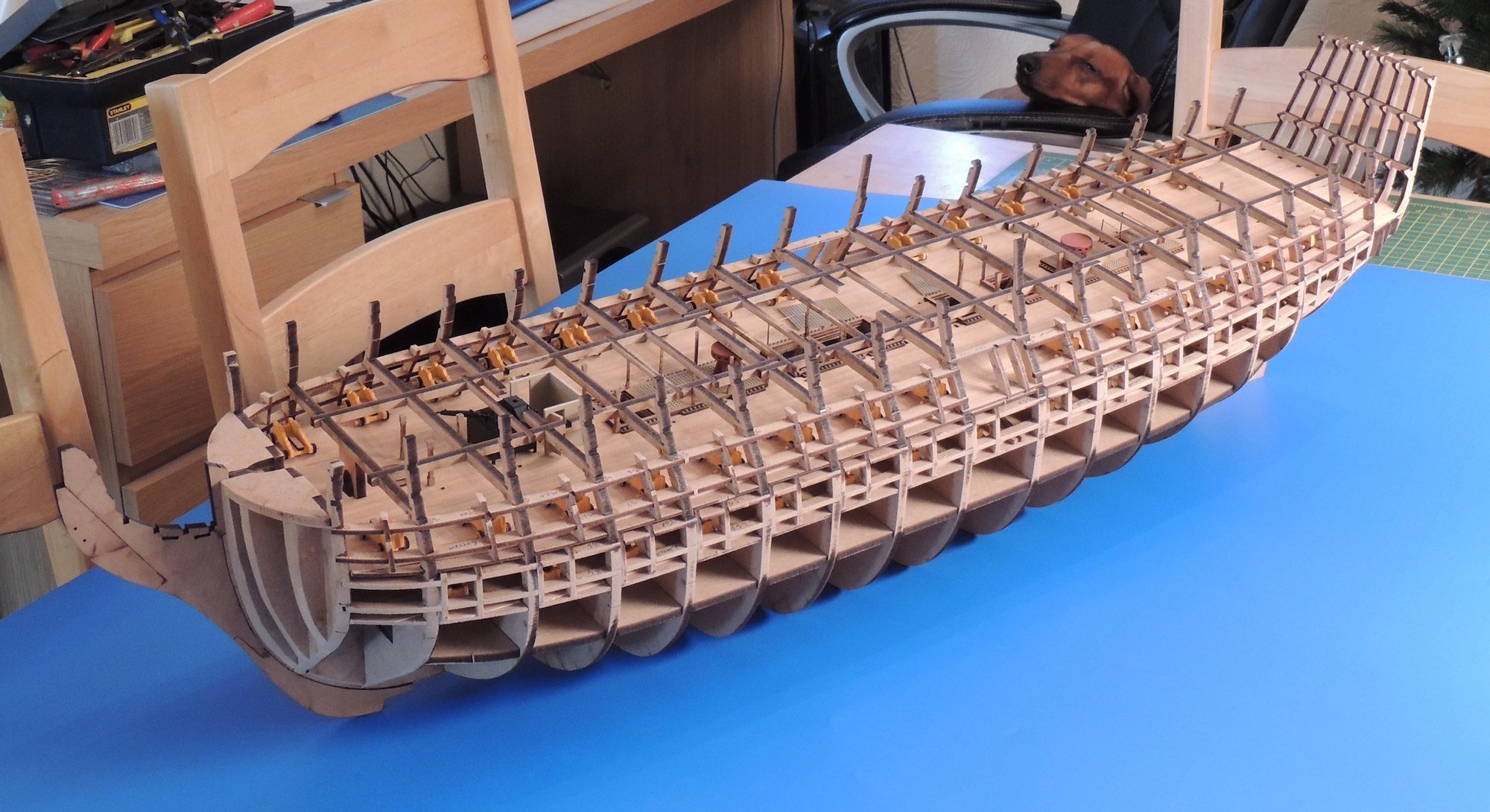
Those slots are definitely there. They are in the middle sandwich of the bulwark...the large side pattern you originally installed to the outer frame. Look here and you'll see them on the parts plans:
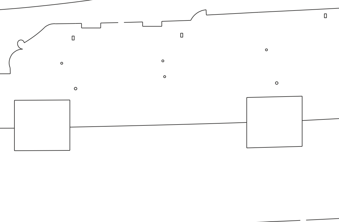
-
Those areas are just neatened, filled and finished, then painted black. There are no parts that fit there. The shed section between mid deck and forecastle gunwales, that's just the same with those little slots to fit the timberheads.
-
You can use thread for lashing, but I pinned in position first with a small length of 1mm brass wire.
- 109 replies
-
- 1
-

-
- Vanguard Models
- Flirt
- (and 1 more)
-
I'm sure someone already did the heavy lifting before the kit was released 😉😝 I did try to make you a manual that showed everything in the smallest detail.
-
Blame me! 🤣
-
She's looking beautiful, and your work is always so clean.
-
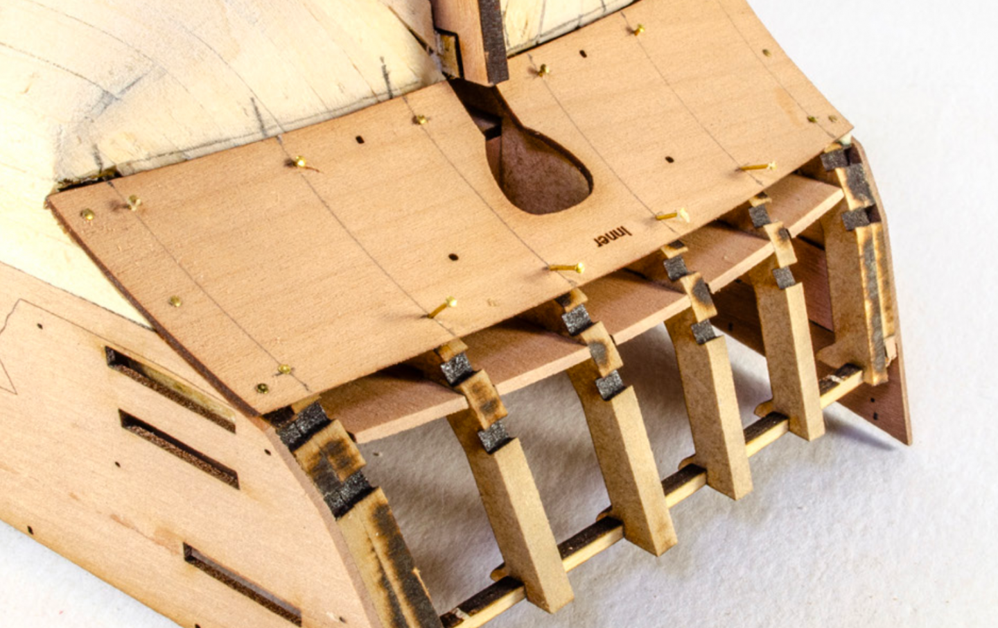
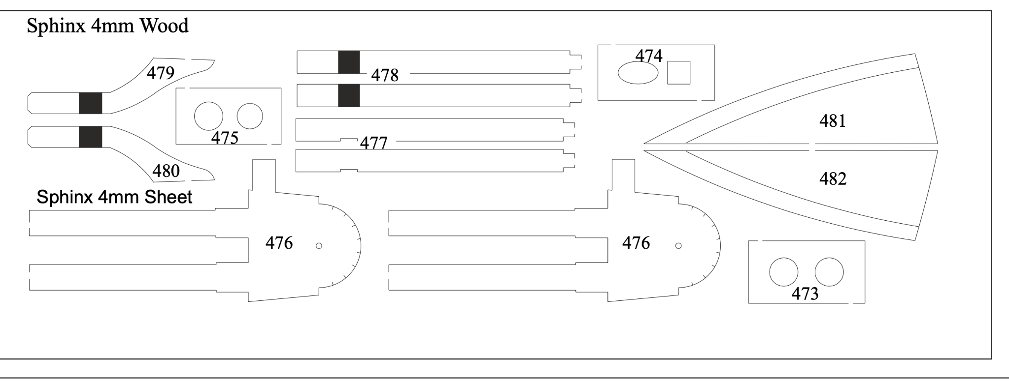
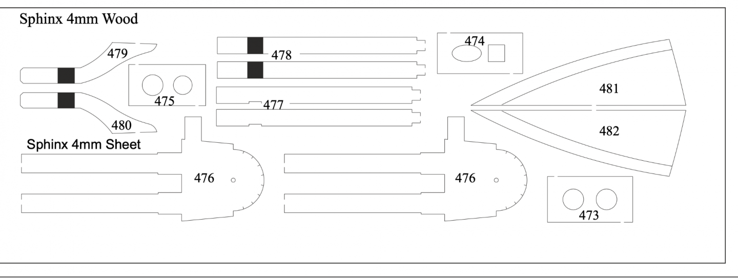
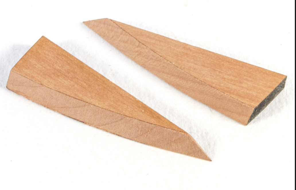
Glenn, that roof looks like MDF. That is supposed to be pear. Have you used the right parts? The pear parts are engraved with the bevel shape for roof. If didn't need to be manually marked. If you still have the pear, remove material from the rear edge so the curve matches your gallery, then bevel to the curve to create the inward sloping roof. Parts 481 and 482:
-
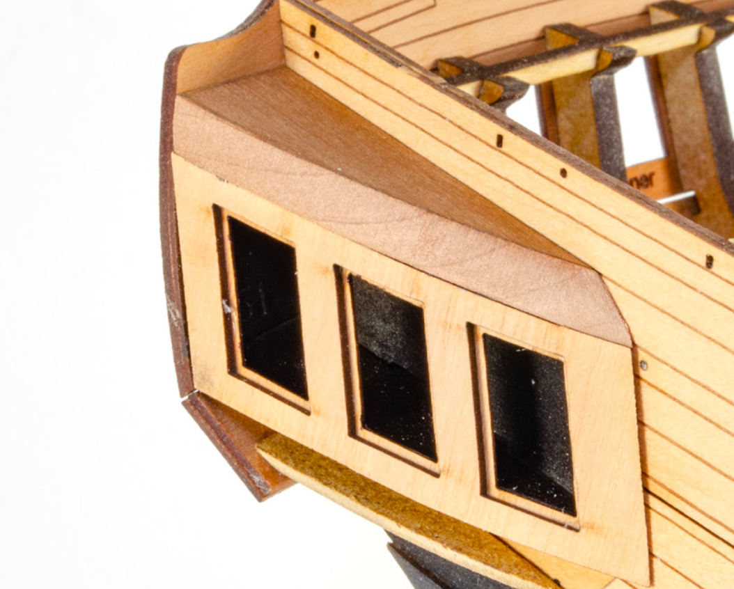
I can see you cut it down to match the flow of the gallery, but where the gallery reaches roof height, the roof is bevelled inwards at an angle. For example, if you'd removed the excess material from the straight edge, the curved shape would have matched your gallery curve, the part would then have been bevelled so the roof leaned inwards from the gallery. Look at the shape of my roof angle at the front. It's not vertical. That shows the bevel where the roof leans inwards.
-
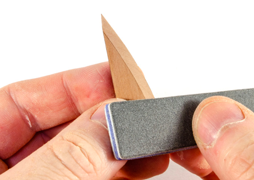
Hi Glenn, You needed to shape/bevel those roof sections before fitting, to allow the upper decorative trim to fit, plus you have that PE shingle to fit too. Test the fit of those parts before proceeding further.
-
Rotary tool recommendations, preferences
James H replied to Steve116's topic in Modeling tools and Workshop Equipment
I use a Dremel Pro and have loads of attachments for it. Can't fault it whatsoever. -
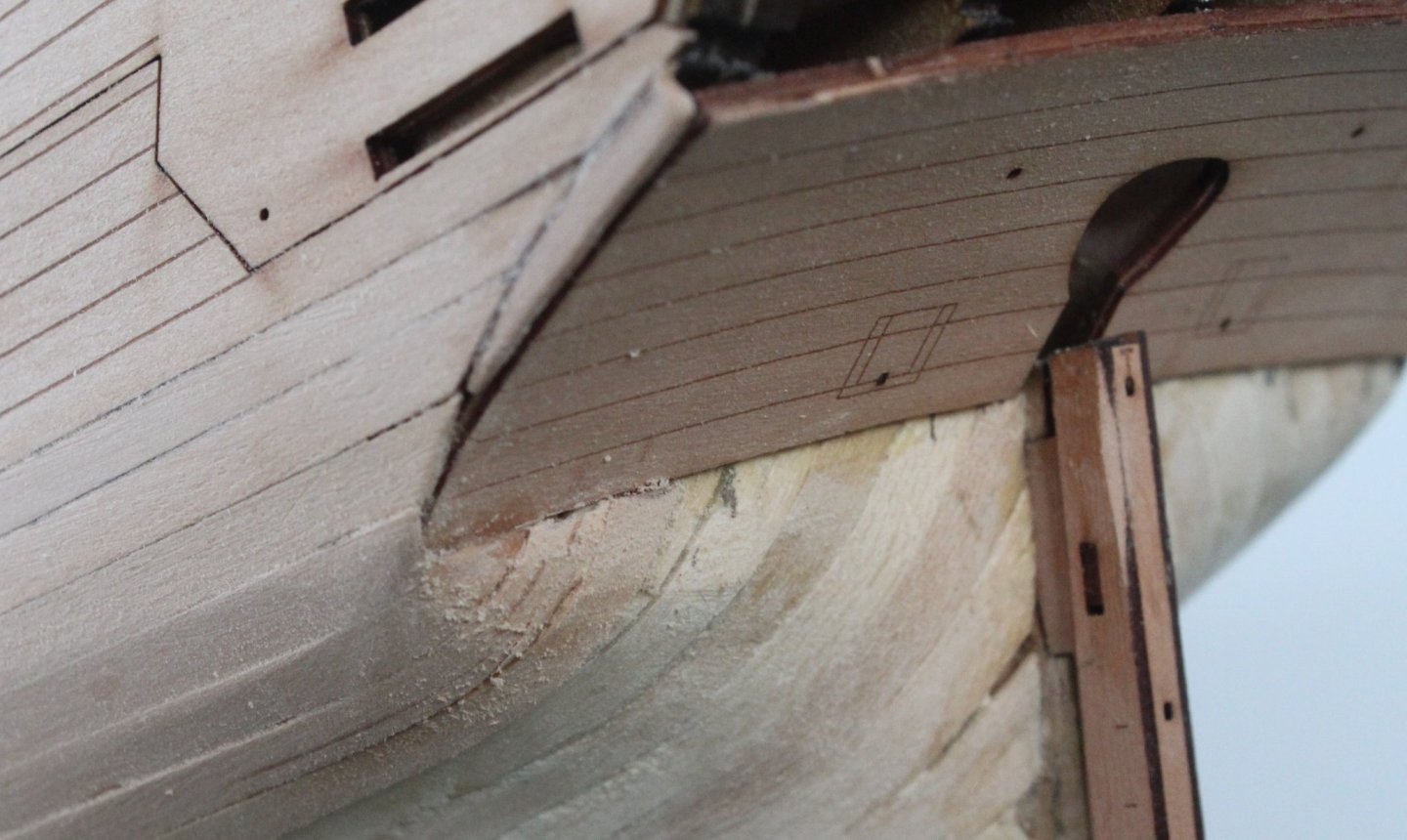
Ok, been taking a good look through this and that problem you're encountering. When I built my prototype, I originally set the stern counter too low, meaning the stern fascia was too low to the bulwarks. You'll see my correction in plan where I said about elevating 2mm to the lower side of slot. That measurement is correct. Take a look at this picture from my own build: Where I made my mistake was not making the top corner of the counter sit at the point on the side pattern where the angle changes....adjacent to the bottom of that slot you see nearest to us in the pic. It's literally only 2mm. Elevating to there will fix the issue......but. ...in your pic, the counter isn't in the correct position with its angle and doesnt sit in relation to the end of the side patterns. You had to put a filler piece in here to compensate, dropping that lower edge to create the gap you have. If everything isn't looked at stages ahead to check for any effect of impact, then you can't retroactively push yourself to the point where everything will align. To be honest, I'd rip that stern counter off and start that area again so the part is sitting properly into that curve. I can't see any way around the other alignment problems you'll face further down the line with rails etc.